EP2626662A1 - Methods and apparatus to disrupt the engine of a vehicle - Google Patents
Methods and apparatus to disrupt the engine of a vehicle Download PDFInfo
- Publication number
- EP2626662A1 EP2626662A1 EP12166887.5A EP12166887A EP2626662A1 EP 2626662 A1 EP2626662 A1 EP 2626662A1 EP 12166887 A EP12166887 A EP 12166887A EP 2626662 A1 EP2626662 A1 EP 2626662A1
- Authority
- EP
- European Patent Office
- Prior art keywords
- engine
- vehicle
- frequency
- transmit antenna
- frequencies
- Prior art date
- Legal status (The legal status is an assumption and is not a legal conclusion. Google has not performed a legal analysis and makes no representation as to the accuracy of the status listed.)
- Granted
Links
Images


Classifications
-
- F—MECHANICAL ENGINEERING; LIGHTING; HEATING; WEAPONS; BLASTING
- F41—WEAPONS
- F41H—ARMOUR; ARMOURED TURRETS; ARMOURED OR ARMED VEHICLES; MEANS OF ATTACK OR DEFENCE, e.g. CAMOUFLAGE, IN GENERAL
- F41H13/00—Means of attack or defence not otherwise provided for
- F41H13/0043—Directed energy weapons, i.e. devices that direct a beam of high energy content toward a target for incapacitating or destroying the target
- F41H13/0075—Directed energy weapons, i.e. devices that direct a beam of high energy content toward a target for incapacitating or destroying the target the high-energy beam being a radiofrequency beam
Definitions
- exemplary techniques include road blocks, barricades, and tack strips.
- these techniques may have limited effectiveness and may present safety issues. For example, obstacles such as barricades, patrol cars, nets, and tack strips on a public road, can create dangerous conditions if vehicle operators escalate the situation. A driver may attempt to go through a roadblock by speeding through barricades.
- roadblocks typically require the services of law enforcement officers for setup, which requires advance notice and planning. In the event that the vehicle forces its way through the barricade, officers may engage in a dangerous high-speed pursuit.
- EMP electromagnetic pulse
- high power microwaves require high energy levels that are difficult to deploy in the field.
- high power microwaves requires a high power microwave source that is difficult to deploy and package.
- EMP and high power microwaves may be unsafe for people in the area of application.
- microwave radiation is directed toward the vehicle to disable or inhibit electronic components of the vehicle. It is difficult to direct the microwave energy directly against a single vehicle.
- the microwave radiation is adapted to disable a particular vehicle's electronic components, all or many of the vehicles in the vicinity of the targeted vehicle may also be temporarily or permanently disabled. Disabling non-targeted vehicles may become a hazard to law enforcement personnel and public.
- the present invention provides method and apparatus for disabling a vehicle by disrupting an engine control unit (ECU).
- a receiver is used to monitor engine parameters, such as ignition timing, to detect disruption caused by a particular frequency transmitted by a transmit antenna.
- the system can dwell on this frequency to disable the vehicle. With this arrangement, a vehicle can be quickly and safely disabled. While exemplary embodiments of the invention are shown and described in conjunction with particular frequencies, power, vehicles and engine control unit characteristics, it is understood that embodiments of the invention are applicable to applications in which it is desirable to disrupt and/or stop an engine.
- a system comprises: a transmit antenna, a controller to control frequencies transmitted by the transmit antenna, a receive antenna, and a signal processor to process information from the receive antenna to identify a frequency transmitted by the transmit antenna that disrupts operation of an engine, wherein the controller controls the signal transmitted by the transmit antenna to dwell on the frequency that disrupts the engine.
- a vehicle checkpoint system comprises: at least one system to disable vehicles, comprising: a transmit antenna, a controller to control frequencies transmitted by the transmit antenna, a receive antenna, and a signal processor to process information from the receive antenna to identify a frequency transmitted by the transmit antenna that disrupts operation of an engine, wherein the controller controls the signal transmitted by the transmit antenna to dwell on the frequency that disrupts the engine.
- a method comprises: transmitting a range of frequencies targeting a vehicle, monitoring performance of an engine of the vehicle, determining a first frequency in the range of frequencies that disrupts operation of the engine from the engine performance monitoring, and dwelling on the first frequency to maintain disruption of the engine.
- exemplary embodiments of the invention enable disruption of an engine control unit (ECU) of a vehicle.
- a system employs a scanning VHF/UHF signal using RF tones to disrupt the vehicle ECU, detect the disrupting frequency, and dwell on the disrupting frequency to bring the vehicle to a stop.
- Exemplary embodiments of the system can be located at fixed location, such as a checkpoint, a mobile vehicle, or other platform.
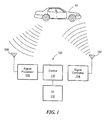
- FIG. 1 shows an exemplary vehicle disruption system 100 in accordance with exemplary embodiments of the invention.
- the system includes a transmit antenna 102 to transmit a range of frequencies while illuminating a target 10, such as vehicle.
- a signal controller 104 controls the characteristics of the transmitted signals.
- a receive antenna 106 receives a signal emitted by the internal combustion engine ignition system of the vehicle 10.
- a signal processor 108 is coupled to the receive antenna 106 and to a control module 110 that controls overall operation of the system.
- a user interface 112 is coupled to the controller 110 to enable a user to interact with the system.
- signals emitted by the engine correspond to the vehicle ignition timing and other characteristics that factor in to frequency susceptibility of the internal combustion engine.
- the signal processor 108 analyzes the received information and determines scan and dwell tones that can be transmitted by the transmit antenna 102 to initiate disruption and eventual default of the ECU controlling the ignition timing of the internal combustion engine.
- the signal controller 104 controls scan and dwell signal transmission over a defined frequency range to determine the optimally disruptive frequency tone by monitoring the ignition response. Continued signal transmission at the frequency of susceptibility results in ECU default until the signal is removed.
- a selected area is radiated for one or more specific vehicles. Since the transmitted frequency corresponds to engine timing for a specific vehicle, the system can disrupt a targeted vehicle in the midst of several vehicles without affecting the non-targeted vehicles. With an array for the transmission, the beam width can be narrow or wide depending on the application.
- the engine By disrupting the vehicle ECU, the engine will stop in milliseconds.
- the ECU can go into a default mode in seconds, thereby requiring much less to power (e.g., 8 dB) to maintain disruption to the ECU and prevent the engine from restarting.
- the ECU Upon removal of the disrupting signal, the ECU can regain normal functionality without damage.
- the closed loop feedback determines the most disruptive frequency tone to produce an ECU default. In addition, this results in an inability of the ECU to reacquire at a much lower power level.
- the disruptive dwell tone may be modulated to reduce the power level compared with a continuous wave transmitted tone.
- a transmitter includes a power combined GaN Amplifier for provide CW power in the order of 170 kW for ECU disruption at about 100m and for 10m about 17W.
- a series of vehicle disruption systems 200a-N are distributed along a vehicle pathway 20.
- the distributed systems are synchronized by a remote receiver/processor to focus the energy at a target vehicle/ECU 10.
- a single receive antenna monitors engine operation of a targeted vehicle. This arrangement is well suited for vehicle checkpoints, such as border crossings.
- vehicle disruption systems are hidden and/or camouflaged.
- An aggressive vehicle can be disabled from a hidden disruption system.
- An operator of the vehicle may not even be aware that the vehicle has been targeted for disruption.
- the system 100 illuminates the vehicle over a range of frequencies, monitors a response of the vehicle engine, and identifies the frequency of the signal that disrupts operation of the vehicle ECU.
- inventions of an inventive vehicle disruption system can be used for any vehicle having electronic ignition control.
- Exemplary vehicles include automobiles, motorcycles, boats, armored vehicles, snowmachines, and the like.
- a transmit antenna comprises a series of antennas identified as Part No. FRF-110A from First RF corporation in Boulder, CO.
- the antennas are arranged in a 3 x 4 lattice on a mobile platform shown as a truck.
- the receive antenna is an omni operating at frequencies higher than those of the transmit antenna.
- FIG. 4 shows an exemplary sequence of steps for providing vehicle disruption in accordance with exemplary embodiments of the invention.
- an object of interest such as a vehicle
- the target is illuminated by transmitting signals in a range of frequencies in step 402.
- a receive antenna monitors operation of the engine, such as ignition timing.
- the information from the receive antenna is used to detect disruption of engine operation due to the signals from the transmit antenna. More particularly, the system analyzes operation of the engine to identify the specific frequency that produces the most disruption. It is understood that transmit and receive operations are coordinated in a known manner.
- the signal of maximum disruption is transmitted by the transmit antenna to disable the vehicle. Once the vehicle is disabled, the power level can be decreased to a level that prevents restart of the engine.
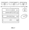
- a computer includes a processor 502, a volatile memory 504, an output device 505, a non-volatile memory 506 (e.g., hard disk), and a graphical user interface (GUI) 508 (e.g., a mouse, a keyboard, a display, for example).
- the non-volatile memory 506 stores computer instructions 512, an operating system 516 and data 518, for example.
- the computer instructions 512 are executed by the processor 502 out of volatile memory 504 to perform all or part of the processing described above.
- An article 519 can comprise a machine-readable medium that stores executable instructions causing a machine to perform any portion of the processing described herein.
- Processing is not limited to use with the hardware and software described herein and may find applicability in any computing or processing environment and with any type of machine or set of machines that is capable of running a computer program. Processing may be implemented in hardware, software, or a combination of the two. Processing may be implemented in computer programs executed on programmable computers/machines that each includes a processor, a storage medium or other article of manufacture that is readable by the processor (including volatile and non-volatile memory and/or storage elements), at least one input device, and one or more output devices. Programs may be implemented in a high level procedural or object-oriented programming language to communicate with a computer system. However, the programs may be implemented in assembly or machine language.
- the language may be a compiled or an interpreted language and it may be deployed in any form, including as a stand-alone program or as a module, component, subroutine, or other unit suitable for use in a computing environment.
- a computer program may be deployed to be executed on one computer or on multiple computers at one site or distributed across multiple sites and interconnected by a communication network.
- a computer program may be stored on a storage medium or device (e.g., CD-ROM, hard disk, or magnetic diskette) that is readable by a general or special purpose programmable computer for configuring and operating the computer when the storage medium or device is read by the computer to perform processing.
Landscapes
- Engineering & Computer Science (AREA)
- Radar, Positioning & Navigation (AREA)
- Remote Sensing (AREA)
- General Engineering & Computer Science (AREA)
- Lock And Its Accessories (AREA)
- Control Of Vehicle Engines Or Engines For Specific Uses (AREA)
Abstract
Description
- The present application is a continuation-in-part of
U.S. Patent Application No. 12/581,087, filed on October 16, 2009 - As is known in the art, there are a variety of techniques to deal with vehicle drivers that do not operate their vehicle safely or have bad intentions. Exemplary techniques include road blocks, barricades, and tack strips. However, these techniques may have limited effectiveness and may present safety issues. For example, obstacles such as barricades, patrol cars, nets, and tack strips on a public road, can create dangerous conditions if vehicle operators escalate the situation. A driver may attempt to go through a roadblock by speeding through barricades. Furthermore, roadblocks typically require the services of law enforcement officers for setup, which requires advance notice and planning. In the event that the vehicle forces its way through the barricade, officers may engage in a dangerous high-speed pursuit.
- Other known techniques for stopping vehicles include the use of electromagnetic pulse (EMP) or high power microwaves to disrupt the electronic components of the vehicles. However, the use of EMP to disable a moving vehicle requires high energy levels that are difficult to deploy in the field. Similarly, the use of high power microwaves requires a high power microwave source that is difficult to deploy and package. Furthermore, EMP and high power microwaves may be unsafe for people in the area of application. When high power microwaves or EMPs are used to stop a moving vehicle, microwave radiation is directed toward the vehicle to disable or inhibit electronic components of the vehicle. It is difficult to direct the microwave energy directly against a single vehicle. Thus, when the microwave radiation is adapted to disable a particular vehicle's electronic components, all or many of the vehicles in the vicinity of the targeted vehicle may also be temporarily or permanently disabled. Disabling non-targeted vehicles may become a hazard to law enforcement personnel and public.
- The present invention provides method and apparatus for disabling a vehicle by disrupting an engine control unit (ECU). In an exemplary embodiment, a receiver is used to monitor engine parameters, such as ignition timing, to detect disruption caused by a particular frequency transmitted by a transmit antenna. The system can dwell on this frequency to disable the vehicle. With this arrangement, a vehicle can be quickly and safely disabled. While exemplary embodiments of the invention are shown and described in conjunction with particular frequencies, power, vehicles and engine control unit characteristics, it is understood that embodiments of the invention are applicable to applications in which it is desirable to disrupt and/or stop an engine.
- In one aspect of the invention, a system comprises: a transmit antenna, a controller to control frequencies transmitted by the transmit antenna, a receive antenna, and a signal processor to process information from the receive antenna to identify a frequency transmitted by the transmit antenna that disrupts operation of an engine, wherein the controller controls the signal transmitted by the transmit antenna to dwell on the frequency that disrupts the engine.
- In another aspect of the invention, a vehicle checkpoint system comprises: at least one system to disable vehicles, comprising: a transmit antenna, a controller to control frequencies transmitted by the transmit antenna, a receive antenna, and a signal processor to process information from the receive antenna to identify a frequency transmitted by the transmit antenna that disrupts operation of an engine, wherein the controller controls the signal transmitted by the transmit antenna to dwell on the frequency that disrupts the engine.
- In a further aspect of the invention, a method comprises: transmitting a range of frequencies targeting a vehicle, monitoring performance of an engine of the vehicle, determining a first frequency in the range of frequencies that disrupts operation of the engine from the engine performance monitoring, and dwelling on the first frequency to maintain disruption of the engine.
- The foregoing features of this invention, as well as the invention itself, may be more fully understood from the following description of the drawings in which:
-
FIG. 1 is a schematic representation of an exemplary vehicle disruption system in accordance with exemplary embodiments of the invention; -
FIG. 2 is a schematic representation of a checkpoint having at least one vehicle disruption system; -
FIG. 3 is a pictorial representation of a transmit antenna array that can form a part of the system ofFIG. 1 ; -
FIG. 4 is a flow diagram showing an exemplary sequence of steps for implementing vehicle disruption in accordance with exemplary embodiments of the invention; and -
FIG. 5 is a schematic representation of an exemplary computer that can perform at least of the processing for vehicle disruption. - In general, exemplary embodiments of the invention enable disruption of an engine control unit (ECU) of a vehicle. In one embodiment, a system employs a scanning VHF/UHF signal using RF tones to disrupt the vehicle ECU, detect the disrupting frequency, and dwell on the disrupting frequency to bring the vehicle to a stop. Exemplary embodiments of the system can be located at fixed location, such as a checkpoint, a mobile vehicle, or other platform.
-
FIG. 1 shows an exemplaryvehicle disruption system 100 in accordance with exemplary embodiments of the invention. The system includes atransmit antenna 102 to transmit a range of frequencies while illuminating atarget 10, such as vehicle. Asignal controller 104 controls the characteristics of the transmitted signals. - A
receive antenna 106 receives a signal emitted by the internal combustion engine ignition system of thevehicle 10. Asignal processor 108 is coupled to the receiveantenna 106 and to acontrol module 110 that controls overall operation of the system. Auser interface 112 is coupled to thecontroller 110 to enable a user to interact with the system. - In general, signals emitted by the engine correspond to the vehicle ignition timing and other characteristics that factor in to frequency susceptibility of the internal combustion engine. The
signal processor 108 analyzes the received information and determines scan and dwell tones that can be transmitted by thetransmit antenna 102 to initiate disruption and eventual default of the ECU controlling the ignition timing of the internal combustion engine. In general, thesignal controller 104 controls scan and dwell signal transmission over a defined frequency range to determine the optimally disruptive frequency tone by monitoring the ignition response. Continued signal transmission at the frequency of susceptibility results in ECU default until the signal is removed. - In one embodiment, a selected area is radiated for one or more specific vehicles. Since the transmitted frequency corresponds to engine timing for a specific vehicle, the system can disrupt a targeted vehicle in the midst of several vehicles without affecting the non-targeted vehicles. With an array for the transmission, the beam width can be narrow or wide depending on the application.
- It is understood that with feedback from engine operation, it can be determined what frequency is effective to disrupt the engine ECU. It is believed that signals are coupling into the ECU through its wiring harness to cause the disruptive effect. It is believed that the disruptions are temporary because the communication between the ECU and sensors are 'jammed'.
- By disrupting the vehicle ECU, the engine will stop in milliseconds. The ECU can go into a default mode in seconds, thereby requiring much less to power (e.g., 8 dB) to maintain disruption to the ECU and prevent the engine from restarting. Upon removal of the disrupting signal, the ECU can regain normal functionality without damage.
- The closed loop feedback determines the most disruptive frequency tone to produce an ECU default. In addition, this results in an inability of the ECU to reacquire at a much lower power level. The disruptive dwell tone may be modulated to reduce the power level compared with a continuous wave transmitted tone.
- It has been found that most ECUs have susceptible frequencies that fall within VHF and UHF bands. In one embodiment, a transmitter includes a power combined GaN Amplifier for provide CW power in the order of 170 kW for ECU disruption at about 100m and for 10m about 17W.
- In one embodiment shown in
FIG. 2 , a series ofvehicle disruption systems 200a-N are distributed along avehicle pathway 20. The distributed systems are synchronized by a remote receiver/processor to focus the energy at a target vehicle/ECU 10. With this arrangement, higher levels of energy are present at thetarget 20 to minimize energy levels in the area in the pathway vicinity. In one embodiment, a single receive antenna monitors engine operation of a targeted vehicle. This arrangement is well suited for vehicle checkpoints, such as border crossings. - In an exemplary embodiment, vehicle disruption systems are hidden and/or camouflaged. An aggressive vehicle can be disabled from a hidden disruption system. An operator of the vehicle may not even be aware that the vehicle has been targeted for disruption.
- It should be noted that no a priori information is required by exemplary embodiments of a vehicle disruption system. The
system 100 illuminates the vehicle over a range of frequencies, monitors a response of the vehicle engine, and identifies the frequency of the signal that disrupts operation of the vehicle ECU. - It is understood that embodiments of an inventive vehicle disruption system can be used for any vehicle having electronic ignition control. Exemplary vehicles include automobiles, motorcycles, boats, armored vehicles, snowmachines, and the like.
- A variety of suitable antennas can be used. In one particular embodiment, a transmit antenna comprises a series of antennas identified as Part No. FRF-110A from First RF corporation in Boulder, CO. In one embodiment shown in
FIG. 3 , the antennas are arranged in a 3 x 4 lattice on a mobile platform shown as a truck. In one embodiment, the receive antenna is an omni operating at frequencies higher than those of the transmit antenna. -
FIG. 4 shows an exemplary sequence of steps for providing vehicle disruption in accordance with exemplary embodiments of the invention. Instep 400, an object of interest, such as a vehicle, is targeted. The target is illuminated by transmitting signals in a range of frequencies instep 402. During illumination of the vehicle, in step 404 a receive antenna monitors operation of the engine, such as ignition timing. Instep 406, the information from the receive antenna is used to detect disruption of engine operation due to the signals from the transmit antenna. More particularly, the system analyzes operation of the engine to identify the specific frequency that produces the most disruption. It is understood that transmit and receive operations are coordinated in a known manner. Instep 408, the signal of maximum disruption is transmitted by the transmit antenna to disable the vehicle. Once the vehicle is disabled, the power level can be decreased to a level that prevents restart of the engine. - It is understood that engine operating characteristics can be stored in a database, as described in
U.S. Patent Application No. 12,581,087 - Referring to
FIG. 5 , a computer includes aprocessor 502, avolatile memory 504, anoutput device 505, a non-volatile memory 506 (e.g., hard disk), and a graphical user interface (GUI) 508 (e.g., a mouse, a keyboard, a display, for example). Thenon-volatile memory 506stores computer instructions 512, anoperating system 516 anddata 518, for example. In one example, thecomputer instructions 512 are executed by theprocessor 502 out ofvolatile memory 504 to perform all or part of the processing described above. Anarticle 519 can comprise a machine-readable medium that stores executable instructions causing a machine to perform any portion of the processing described herein. - Processing is not limited to use with the hardware and software described herein and may find applicability in any computing or processing environment and with any type of machine or set of machines that is capable of running a computer program. Processing may be implemented in hardware, software, or a combination of the two. Processing may be implemented in computer programs executed on programmable computers/machines that each includes a processor, a storage medium or other article of manufacture that is readable by the processor (including volatile and non-volatile memory and/or storage elements), at least one input device, and one or more output devices. Programs may be implemented in a high level procedural or object-oriented programming language to communicate with a computer system. However, the programs may be implemented in assembly or machine language. The language may be a compiled or an interpreted language and it may be deployed in any form, including as a stand-alone program or as a module, component, subroutine, or other unit suitable for use in a computing environment. A computer program may be deployed to be executed on one computer or on multiple computers at one site or distributed across multiple sites and interconnected by a communication network. A computer program may be stored on a storage medium or device (e.g., CD-ROM, hard disk, or magnetic diskette) that is readable by a general or special purpose programmable computer for configuring and operating the computer when the storage medium or device is read by the computer to perform processing.
- Having described exemplary embodiments of the invention, it will now become apparent to one of ordinary skill in the art that other embodiments incorporating their concepts may also be used. The embodiments contained herein should not be limited to disclosed embodiments but rather should be limited only by the spirit and scope of the appended claims. All publications and references cited herein are expressly incorporated herein by reference in their entirety.
Claims (17)
- A system, comprising:a transmit antenna;a controller to control frequencies transmitted by the transmit antenna;a receive antenna; anda signal processor to process information from the receive antenna to identify a frequency transmitted by the transmit antenna that disrupts operation of an engine of a vehicle, wherein the controller controls the signal transmitted by the transmit antenna to dwell on the frequency that disrupts the engine.
- The system according to claim 1, wherein a range of frequencies for transmission by the transmit antenna range in specific region of the VHF/UHF bands.
- The system according to claim 1 or claim 2, wherein the information from the receive antenna includes ignition timing.
- The system according to claim 1 or any preceding claim, wherein the dwell frequency disrupts operation of an engine control unit (ECU) coupled to the engine.
- The system according to claim 1 or any preceding claim, wherein the transmit antenna comprises an array.
- The system according to claim 1 or any preceding claim, wherein the system is mounted on a vehicle.
- The system according to claim 1 or any preceding claim, further including a vehicle checkpoint.
- The system of claim 7 wherein the vehicle checkpoint comprises at least one system to disable vehicles which has the transmit antenna, controller, receive antenna, and signal processor of claim 1
- A vehicle checkpoint system, comprising:at least one system to disable vehicles, comprising:a transmit antenna;a controller to control frequencies transmitted by the transmit antenna;a receive antenna; anda signal processor to process information from the receive antenna to identify a frequency transmitted by the transmit antenna that disrupts operation of an engine, wherein the controller controls the signal transmitted by the transmit antenna to dwell on the frequency that disrupts the engine.
- The system according to claim 8 or claim 9, wherein the at least one system to disable vehicles is hidden.
- A method, comprising:transmitting a range of frequencies targeting a vehicle;monitoring performance of an engine of the vehicle;determining a first frequency in the range of frequencies that disrupts operation of the engine from the engine performance monitoring; anddwelling on the first frequency to maintain disruption of the engine.
- The method according to claim 11, wherein the vehicle comprises or more of an automobile, a truck, a boat, a helicopter, and/or snowmobile.
- The method according to claim 11 or claim 12, further including reducing a power of the first frequency after the engine is disabled to a level that prevents engine restart.
- The method according to claim 11, or claim 12, or claim 13, further including monitoring the vehicles at a vehicle checkpoint.
- The method according to claim 11, or any of claims 12 to 14, wherein a range of frequencies for transmission by the transmit antenna range in specific regions of the VHF /UHF bands.
- The method according to claim 11, or any of claims 12 to 15, wherein the information from the receive antenna includes ignition timing.
- The method according to claim 11, or any of claims 12 to 16, wherein the dwell frequency disrupts operation of an engine control unit (ECU) coupled to the engine.
Applications Claiming Priority (1)
| Application Number | Priority Date | Filing Date | Title |
|---|---|---|---|
| US13/372,073 US9079555B2 (en) | 2009-10-16 | 2012-02-13 | Methods and apparatus to disrupt the engine of a vehicle |
Publications (2)
| Publication Number | Publication Date |
|---|---|
| EP2626662A1 true EP2626662A1 (en) | 2013-08-14 |
| EP2626662B1 EP2626662B1 (en) | 2015-04-15 |
Family
ID=46027829
Family Applications (1)
| Application Number | Title | Priority Date | Filing Date |
|---|---|---|---|
| EP20120166887 Active EP2626662B1 (en) | 2012-02-13 | 2012-05-04 | Methods and apparatus to disrupt the engine of a vehicle |
Country Status (2)
| Country | Link |
|---|---|
| EP (1) | EP2626662B1 (en) |
| IL (1) | IL222701A (en) |
Cited By (1)
| Publication number | Priority date | Publication date | Assignee | Title |
|---|---|---|---|---|
| JP2017510189A (en) * | 2014-03-10 | 2017-04-06 | イー2ブイ テクノロジーズ(ユーケー)リミティド | Apparatus and method for remotely stopping a vehicle |
Families Citing this family (1)
| Publication number | Priority date | Publication date | Assignee | Title |
|---|---|---|---|---|
| RU2657143C1 (en) * | 2015-11-06 | 2018-06-08 | Евгений Алексеевич Куликов | System of remote stopping of vehicles |
Citations (3)
| Publication number | Priority date | Publication date | Assignee | Title |
|---|---|---|---|---|
| US5907290A (en) * | 1997-08-22 | 1999-05-25 | The United States Of America As Represented By The Secretary Of The Army | In-road microwave vehicle stopper |
| US20080223641A1 (en) * | 2007-01-30 | 2008-09-18 | Fiore Industries, Inc. | Method and Apparatus for Remotely Disabling Vehicles |
| WO2011046777A1 (en) * | 2009-10-16 | 2011-04-21 | Raytheon Company | Low power microwave vehicle stopper with feedback |
-
2012
- 2012-05-04 EP EP20120166887 patent/EP2626662B1/en active Active
- 2012-10-25 IL IL222701A patent/IL222701A/en active IP Right Grant
Patent Citations (3)
| Publication number | Priority date | Publication date | Assignee | Title |
|---|---|---|---|---|
| US5907290A (en) * | 1997-08-22 | 1999-05-25 | The United States Of America As Represented By The Secretary Of The Army | In-road microwave vehicle stopper |
| US20080223641A1 (en) * | 2007-01-30 | 2008-09-18 | Fiore Industries, Inc. | Method and Apparatus for Remotely Disabling Vehicles |
| WO2011046777A1 (en) * | 2009-10-16 | 2011-04-21 | Raytheon Company | Low power microwave vehicle stopper with feedback |
Cited By (1)
| Publication number | Priority date | Publication date | Assignee | Title |
|---|---|---|---|---|
| JP2017510189A (en) * | 2014-03-10 | 2017-04-06 | イー2ブイ テクノロジーズ(ユーケー)リミティド | Apparatus and method for remotely stopping a vehicle |
Also Published As
| Publication number | Publication date |
|---|---|
| EP2626662B1 (en) | 2015-04-15 |
| IL222701A (en) | 2017-01-31 |
Similar Documents
| Publication | Publication Date | Title |
|---|---|---|
| US9079555B2 (en) | Methods and apparatus to disrupt the engine of a vehicle | |
| US8116966B2 (en) | Low power microwave vehicle stopper with feedback | |
| US10197665B2 (en) | Radar false alert reduction | |
| KR102012386B1 (en) | Apparatus for generating a deception signal for a pulse compression signal and method therefor | |
| CN1606889A (en) | Use controller for a wireless communication device | |
| US10698080B2 (en) | Automotive radar for V2X communication | |
| EP1922249B1 (en) | Radiant electromagnetic energy management | |
| WO2016088752A1 (en) | Target detecting apparatus using reflection point information of target | |
| EP2626662B1 (en) | Methods and apparatus to disrupt the engine of a vehicle | |
| US7215276B2 (en) | Radar detector | |
| KR102879765B1 (en) | Intelligent virtual target generation device and method for vehicle collision prevention | |
| KR102443265B1 (en) | Remote vehicle disabling device and method | |
| US5907290A (en) | In-road microwave vehicle stopper | |
| JP2008111773A (en) | Automotive radar equipment | |
| WO2022239420A1 (en) | Movable body supervision system and attack notification method | |
| US20260061966A1 (en) | Auto-immobilization based on tampering or jamming detection | |
| CN108535692B (en) | Automobile positioning method and automobile positioning system | |
| Hamid et al. | Conceptual design of electromagnetic pulse for denied vehicular access application | |
| DE102019130388B4 (en) | Radar device with integrated security capability | |
| Meryem et al. | Security study and challenges of connected autonomous vehicles | |
| KR102836065B1 (en) | Apparatu and method for electronic counter measures | |
| US12123686B2 (en) | Dynamic unmanned threat emitter | |
| BRIZZOLABA | 79 GHz High Resolution Short Range Automotive Radar Evolution. | |
| Jeong et al. | Anti-Drone Technology for Drone Threat Response: Current Status and Future Directions | |
| Hamid et al. | Recent Trends of Electromagnetic Pulse Mean for Denied Vehicular Access Application or Vehicle Immobilization. |
Legal Events
| Date | Code | Title | Description |
|---|---|---|---|
| PUAI | Public reference made under article 153(3) epc to a published international application that has entered the european phase |
Free format text: ORIGINAL CODE: 0009012 |
|
| AK | Designated contracting states |
Kind code of ref document: A1 Designated state(s): AL AT BE BG CH CY CZ DE DK EE ES FI FR GB GR HR HU IE IS IT LI LT LU LV MC MK MT NL NO PL PT RO RS SE SI SK SM TR |
|
| AX | Request for extension of the european patent |
Extension state: BA ME |
|
| 17P | Request for examination filed |
Effective date: 20130912 |
|
| RBV | Designated contracting states (corrected) |
Designated state(s): AL AT BE BG CH CY CZ DE DK EE ES FI FR GB GR HR HU IE IS IT LI LT LU LV MC MK MT NL NO PL PT RO RS SE SI SK SM TR |
|
| GRAP | Despatch of communication of intention to grant a patent |
Free format text: ORIGINAL CODE: EPIDOSNIGR1 |
|
| INTG | Intention to grant announced |
Effective date: 20150112 |
|
| GRAS | Grant fee paid |
Free format text: ORIGINAL CODE: EPIDOSNIGR3 |
|
| GRAA | (expected) grant |
Free format text: ORIGINAL CODE: 0009210 |
|
| AK | Designated contracting states |
Kind code of ref document: B1 Designated state(s): AL AT BE BG CH CY CZ DE DK EE ES FI FR GB GR HR HU IE IS IT LI LT LU LV MC MK MT NL NO PL PT RO RS SE SI SK SM TR |
|
| REG | Reference to a national code |
Ref country code: GB Ref legal event code: FG4D Ref country code: CH Ref legal event code: EP |
|
| REG | Reference to a national code |
Ref country code: IE Ref legal event code: FG4D |
|
| REG | Reference to a national code |
Ref country code: AT Ref legal event code: REF Ref document number: 722230 Country of ref document: AT Kind code of ref document: T Effective date: 20150515 |
|
| REG | Reference to a national code |
Ref country code: DE Ref legal event code: R096 Ref document number: 602012006635 Country of ref document: DE Effective date: 20150528 |
|
| REG | Reference to a national code |
Ref country code: NL Ref legal event code: VDEP Effective date: 20150415 |
|
| REG | Reference to a national code |
Ref country code: AT Ref legal event code: MK05 Ref document number: 722230 Country of ref document: AT Kind code of ref document: T Effective date: 20150415 |
|
| REG | Reference to a national code |
Ref country code: LT Ref legal event code: MG4D |
|
| PG25 | Lapsed in a contracting state [announced via postgrant information from national office to epo] |
Ref country code: NL Free format text: LAPSE BECAUSE OF FAILURE TO SUBMIT A TRANSLATION OF THE DESCRIPTION OR TO PAY THE FEE WITHIN THE PRESCRIBED TIME-LIMIT Effective date: 20150415 |
|
| PG25 | Lapsed in a contracting state [announced via postgrant information from national office to epo] |
Ref country code: LT Free format text: LAPSE BECAUSE OF FAILURE TO SUBMIT A TRANSLATION OF THE DESCRIPTION OR TO PAY THE FEE WITHIN THE PRESCRIBED TIME-LIMIT Effective date: 20150415 Ref country code: HR Free format text: LAPSE BECAUSE OF FAILURE TO SUBMIT A TRANSLATION OF THE DESCRIPTION OR TO PAY THE FEE WITHIN THE PRESCRIBED TIME-LIMIT Effective date: 20150415 Ref country code: FI Free format text: LAPSE BECAUSE OF FAILURE TO SUBMIT A TRANSLATION OF THE DESCRIPTION OR TO PAY THE FEE WITHIN THE PRESCRIBED TIME-LIMIT Effective date: 20150415 Ref country code: ES Free format text: LAPSE BECAUSE OF FAILURE TO SUBMIT A TRANSLATION OF THE DESCRIPTION OR TO PAY THE FEE WITHIN THE PRESCRIBED TIME-LIMIT Effective date: 20150415 Ref country code: NO Free format text: LAPSE BECAUSE OF FAILURE TO SUBMIT A TRANSLATION OF THE DESCRIPTION OR TO PAY THE FEE WITHIN THE PRESCRIBED TIME-LIMIT Effective date: 20150715 Ref country code: PT Free format text: LAPSE BECAUSE OF FAILURE TO SUBMIT A TRANSLATION OF THE DESCRIPTION OR TO PAY THE FEE WITHIN THE PRESCRIBED TIME-LIMIT Effective date: 20150817 |
|
| PG25 | Lapsed in a contracting state [announced via postgrant information from national office to epo] |
Ref country code: RS Free format text: LAPSE BECAUSE OF FAILURE TO SUBMIT A TRANSLATION OF THE DESCRIPTION OR TO PAY THE FEE WITHIN THE PRESCRIBED TIME-LIMIT Effective date: 20150415 Ref country code: LV Free format text: LAPSE BECAUSE OF FAILURE TO SUBMIT A TRANSLATION OF THE DESCRIPTION OR TO PAY THE FEE WITHIN THE PRESCRIBED TIME-LIMIT Effective date: 20150415 Ref country code: IS Free format text: LAPSE BECAUSE OF FAILURE TO SUBMIT A TRANSLATION OF THE DESCRIPTION OR TO PAY THE FEE WITHIN THE PRESCRIBED TIME-LIMIT Effective date: 20150815 Ref country code: AT Free format text: LAPSE BECAUSE OF FAILURE TO SUBMIT A TRANSLATION OF THE DESCRIPTION OR TO PAY THE FEE WITHIN THE PRESCRIBED TIME-LIMIT Effective date: 20150415 Ref country code: GR Free format text: LAPSE BECAUSE OF FAILURE TO SUBMIT A TRANSLATION OF THE DESCRIPTION OR TO PAY THE FEE WITHIN THE PRESCRIBED TIME-LIMIT Effective date: 20150716 |
|
| REG | Reference to a national code |
Ref country code: CH Ref legal event code: PL |
|
| REG | Reference to a national code |
Ref country code: DE Ref legal event code: R097 Ref document number: 602012006635 Country of ref document: DE |
|
| PG25 | Lapsed in a contracting state [announced via postgrant information from national office to epo] |
Ref country code: EE Free format text: LAPSE BECAUSE OF FAILURE TO SUBMIT A TRANSLATION OF THE DESCRIPTION OR TO PAY THE FEE WITHIN THE PRESCRIBED TIME-LIMIT Effective date: 20150415 Ref country code: CH Free format text: LAPSE BECAUSE OF NON-PAYMENT OF DUE FEES Effective date: 20150531 Ref country code: MC Free format text: LAPSE BECAUSE OF FAILURE TO SUBMIT A TRANSLATION OF THE DESCRIPTION OR TO PAY THE FEE WITHIN THE PRESCRIBED TIME-LIMIT Effective date: 20150415 Ref country code: DK Free format text: LAPSE BECAUSE OF FAILURE TO SUBMIT A TRANSLATION OF THE DESCRIPTION OR TO PAY THE FEE WITHIN THE PRESCRIBED TIME-LIMIT Effective date: 20150415 Ref country code: LI Free format text: LAPSE BECAUSE OF NON-PAYMENT OF DUE FEES Effective date: 20150531 |
|
| PLBE | No opposition filed within time limit |
Free format text: ORIGINAL CODE: 0009261 |
|
| STAA | Information on the status of an ep patent application or granted ep patent |
Free format text: STATUS: NO OPPOSITION FILED WITHIN TIME LIMIT |
|
| REG | Reference to a national code |
Ref country code: IE Ref legal event code: MM4A |
|
| PG25 | Lapsed in a contracting state [announced via postgrant information from national office to epo] |
Ref country code: RO Free format text: LAPSE BECAUSE OF NON-PAYMENT OF DUE FEES Effective date: 20150415 Ref country code: SK Free format text: LAPSE BECAUSE OF FAILURE TO SUBMIT A TRANSLATION OF THE DESCRIPTION OR TO PAY THE FEE WITHIN THE PRESCRIBED TIME-LIMIT Effective date: 20150415 Ref country code: CZ Free format text: LAPSE BECAUSE OF FAILURE TO SUBMIT A TRANSLATION OF THE DESCRIPTION OR TO PAY THE FEE WITHIN THE PRESCRIBED TIME-LIMIT Effective date: 20150415 Ref country code: PL Free format text: LAPSE BECAUSE OF FAILURE TO SUBMIT A TRANSLATION OF THE DESCRIPTION OR TO PAY THE FEE WITHIN THE PRESCRIBED TIME-LIMIT Effective date: 20150415 |
|
| 26N | No opposition filed |
Effective date: 20160118 |
|
| REG | Reference to a national code |
Ref country code: FR Ref legal event code: PLFP Year of fee payment: 5 |
|
| PG25 | Lapsed in a contracting state [announced via postgrant information from national office to epo] |
Ref country code: IE Free format text: LAPSE BECAUSE OF NON-PAYMENT OF DUE FEES Effective date: 20150504 |
|
| PG25 | Lapsed in a contracting state [announced via postgrant information from national office to epo] |
Ref country code: SI Free format text: LAPSE BECAUSE OF FAILURE TO SUBMIT A TRANSLATION OF THE DESCRIPTION OR TO PAY THE FEE WITHIN THE PRESCRIBED TIME-LIMIT Effective date: 20150415 |
|
| PG25 | Lapsed in a contracting state [announced via postgrant information from national office to epo] |
Ref country code: BE Free format text: LAPSE BECAUSE OF FAILURE TO SUBMIT A TRANSLATION OF THE DESCRIPTION OR TO PAY THE FEE WITHIN THE PRESCRIBED TIME-LIMIT Effective date: 20150415 |
|
| PG25 | Lapsed in a contracting state [announced via postgrant information from national office to epo] |
Ref country code: MT Free format text: LAPSE BECAUSE OF FAILURE TO SUBMIT A TRANSLATION OF THE DESCRIPTION OR TO PAY THE FEE WITHIN THE PRESCRIBED TIME-LIMIT Effective date: 20150415 |
|
| REG | Reference to a national code |
Ref country code: FR Ref legal event code: PLFP Year of fee payment: 6 |
|
| PG25 | Lapsed in a contracting state [announced via postgrant information from national office to epo] |
Ref country code: HU Free format text: LAPSE BECAUSE OF FAILURE TO SUBMIT A TRANSLATION OF THE DESCRIPTION OR TO PAY THE FEE WITHIN THE PRESCRIBED TIME-LIMIT; INVALID AB INITIO Effective date: 20120504 Ref country code: SM Free format text: LAPSE BECAUSE OF FAILURE TO SUBMIT A TRANSLATION OF THE DESCRIPTION OR TO PAY THE FEE WITHIN THE PRESCRIBED TIME-LIMIT Effective date: 20150415 Ref country code: BG Free format text: LAPSE BECAUSE OF FAILURE TO SUBMIT A TRANSLATION OF THE DESCRIPTION OR TO PAY THE FEE WITHIN THE PRESCRIBED TIME-LIMIT Effective date: 20150415 |
|
| PG25 | Lapsed in a contracting state [announced via postgrant information from national office to epo] |
Ref country code: CY Free format text: LAPSE BECAUSE OF FAILURE TO SUBMIT A TRANSLATION OF THE DESCRIPTION OR TO PAY THE FEE WITHIN THE PRESCRIBED TIME-LIMIT Effective date: 20150415 Ref country code: SE Free format text: LAPSE BECAUSE OF FAILURE TO SUBMIT A TRANSLATION OF THE DESCRIPTION OR TO PAY THE FEE WITHIN THE PRESCRIBED TIME-LIMIT Effective date: 20150415 |
|
| PG25 | Lapsed in a contracting state [announced via postgrant information from national office to epo] |
Ref country code: TR Free format text: LAPSE BECAUSE OF FAILURE TO SUBMIT A TRANSLATION OF THE DESCRIPTION OR TO PAY THE FEE WITHIN THE PRESCRIBED TIME-LIMIT Effective date: 20150415 |
|
| PG25 | Lapsed in a contracting state [announced via postgrant information from national office to epo] |
Ref country code: LU Free format text: LAPSE BECAUSE OF NON-PAYMENT OF DUE FEES Effective date: 20150504 |
|
| REG | Reference to a national code |
Ref country code: FR Ref legal event code: PLFP Year of fee payment: 7 |
|
| PG25 | Lapsed in a contracting state [announced via postgrant information from national office to epo] |
Ref country code: MK Free format text: LAPSE BECAUSE OF FAILURE TO SUBMIT A TRANSLATION OF THE DESCRIPTION OR TO PAY THE FEE WITHIN THE PRESCRIBED TIME-LIMIT Effective date: 20150415 |
|
| PG25 | Lapsed in a contracting state [announced via postgrant information from national office to epo] |
Ref country code: AL Free format text: LAPSE BECAUSE OF FAILURE TO SUBMIT A TRANSLATION OF THE DESCRIPTION OR TO PAY THE FEE WITHIN THE PRESCRIBED TIME-LIMIT Effective date: 20150415 |
|
| P01 | Opt-out of the competence of the unified patent court (upc) registered |
Effective date: 20230530 |
|
| PGFP | Annual fee paid to national office [announced via postgrant information from national office to epo] |
Ref country code: DE Payment date: 20250423 Year of fee payment: 14 |
|
| PGFP | Annual fee paid to national office [announced via postgrant information from national office to epo] |
Ref country code: GB Payment date: 20250423 Year of fee payment: 14 |
|
| PGFP | Annual fee paid to national office [announced via postgrant information from national office to epo] |
Ref country code: IT Payment date: 20250423 Year of fee payment: 14 |
|
| PGFP | Annual fee paid to national office [announced via postgrant information from national office to epo] |
Ref country code: FR Payment date: 20250423 Year of fee payment: 14 |