EP2626634A2 - Gasturbinenvormischbrenner - Google Patents
Gasturbinenvormischbrenner Download PDFInfo
- Publication number
- EP2626634A2 EP2626634A2 EP13000607.5A EP13000607A EP2626634A2 EP 2626634 A2 EP2626634 A2 EP 2626634A2 EP 13000607 A EP13000607 A EP 13000607A EP 2626634 A2 EP2626634 A2 EP 2626634A2
- Authority
- EP
- European Patent Office
- Prior art keywords
- channel
- flow guide
- cross
- premix burner
- recess
- Prior art date
- Legal status (The legal status is an assumption and is not a legal conclusion. Google has not performed a legal analysis and makes no representation as to the accuracy of the status listed.)
- Granted
Links
Images


Classifications
-
- F—MECHANICAL ENGINEERING; LIGHTING; HEATING; WEAPONS; BLASTING
- F23—COMBUSTION APPARATUS; COMBUSTION PROCESSES
- F23R—GENERATING COMBUSTION PRODUCTS OF HIGH PRESSURE OR HIGH VELOCITY, e.g. GAS-TURBINE COMBUSTION CHAMBERS
- F23R3/00—Continuous combustion chambers using liquid or gaseous fuel
- F23R3/28—Continuous combustion chambers using liquid or gaseous fuel characterised by the fuel supply
- F23R3/286—Continuous combustion chambers using liquid or gaseous fuel characterised by the fuel supply having fuel-air premixing devices
-
- F—MECHANICAL ENGINEERING; LIGHTING; HEATING; WEAPONS; BLASTING
- F23—COMBUSTION APPARATUS; COMBUSTION PROCESSES
- F23R—GENERATING COMBUSTION PRODUCTS OF HIGH PRESSURE OR HIGH VELOCITY, e.g. GAS-TURBINE COMBUSTION CHAMBERS
- F23R3/00—Continuous combustion chambers using liquid or gaseous fuel
- F23R3/02—Continuous combustion chambers using liquid or gaseous fuel characterised by the air-flow or gas-flow configuration
- F23R3/04—Air inlet arrangements
- F23R3/10—Air inlet arrangements for primary air
- F23R3/12—Air inlet arrangements for primary air inducing a vortex
- F23R3/14—Air inlet arrangements for primary air inducing a vortex by using swirl vanes
-
- Y—GENERAL TAGGING OF NEW TECHNOLOGICAL DEVELOPMENTS; GENERAL TAGGING OF CROSS-SECTIONAL TECHNOLOGIES SPANNING OVER SEVERAL SECTIONS OF THE IPC; TECHNICAL SUBJECTS COVERED BY FORMER USPC CROSS-REFERENCE ART COLLECTIONS [XRACs] AND DIGESTS
- Y02—TECHNOLOGIES OR APPLICATIONS FOR MITIGATION OR ADAPTATION AGAINST CLIMATE CHANGE
- Y02T—CLIMATE CHANGE MITIGATION TECHNOLOGIES RELATED TO TRANSPORTATION
- Y02T50/00—Aeronautics or air transport
- Y02T50/60—Efficient propulsion technologies, e.g. for aircraft
Definitions
- the invention relates to a gas turbine premix burner of a stationary gas turbine or an aircraft gas turbine, wherein the premix burner can be used both in an annular combustion chamber and in a single combustion chamber with only one premix burner.
- annular combustion chamber 15 consists of an upper / radially outer 29 and a lower / radially inner 30 combustion chamber wall, which together form an annular channel. Air and fuel are supplied to the annular combustion chamber 15 through the fuel nozzle 33, as well as air through cooling or Heileinblasö réelleen on the side walls. In the fuel nozzle 33 and in the annular combustion chamber 15, air and fuel are mixed and burned. The air and combustion products are diverted through a combustor exit nozzle 32 toward the turbine 16.
- the premix burners or fuel nozzles 33 in annular combustion chambers 15 of stationary gas turbines or aircraft gas turbines are characterized by the fact that the air and the fuel are selectively directed and mixed.
- Fig. 2 shows schematically the burner / the fuel nozzle for an annular combustion chamber 15. Air and fuel are passed through a plurality of channels 34, wherein the air is twisted by means of flow guide elements 36, so that air and fuel can mix.
- the number of air and fuel channels 34 can be arbitrary.
- the flow guide elements 36 are embedded in the air channels 34, wherein the shape of the air channel according to the prior art is cylindrical and its height does not change over the length of the flow guide.
- the flow guide itself serves to impart to the air flow a twist which is of the order of 10 to 50 degrees. This is done by an aerodynamic shaping, which by the radial stacking of profile sections of the individual flow guide takes place.
- the profile sections are generally identical over the channel height and arranged both axially and circumferentially linearly, ie without axial or tangential offset.
- a profile section of a flow guide element 36 can be described as follows:
- a profile 40 of a flow guide element 36 is the superposition of a skeleton line 38 along a profile chord 39 with a thickness distribution along the chord. These definitions are dimensionless to make them universally applicable.
- the definition of the thickness distribution is characterized in that it represents the thickness along the chord 39 as a fraction of the maximum thickness, see FIGS. 5 and 6 .
- the definition of the skeleton line 38 is such that the local angle of the skeleton line 38 is defined in dimensionless form. This is done with Equation 1 in such a way that the respective value ⁇ at a position I along the chord 38, which connects the leading edge 41 and the trailing edge 42 of the profile 40 (see Fig.
- the two thickness distributions are in Fig. 7 and are defined according to equation 2 or equation 3.
- the representation is made along the dimensionless chord length of any profile section.
- the definition hereby includes the coordinate x, which is defined from 0 to 1 along the chord of dimensionless length 1, where 0 is at the leading edge and 1 at the trailing edge (see FIG Fig. 4 ).
- d 16 ⁇ x - x 2
- d 4 ⁇ x - x 2
- the inventive design of the premix burner can be used both in annular combustion chambers as well as in individual combustion chambers. Furthermore, the invention can also be found in other swirl generators in flow channels application.
Landscapes
- Engineering & Computer Science (AREA)
- Chemical & Material Sciences (AREA)
- Combustion & Propulsion (AREA)
- Mechanical Engineering (AREA)
- General Engineering & Computer Science (AREA)
- Turbine Rotor Nozzle Sealing (AREA)
- Pre-Mixing And Non-Premixing Gas Burner (AREA)
Abstract
Description
- Die Erfindung bezieht sich auf einen Gasturbinenvormischbrenner einer stationären Gasturbine oder einer Fluggasturbine, wobei der Vormischbrenner sowohl bei einer Ringbrennkammer als auch bei einer einzelnen Brennkammer mit nur einem Vormischbrenner eingesetzt werden kann.
- Vormischbrenner sind aus dem Stand der Technik in unterschiedlichsten Ausgestaltungsformen vorbekannt. Sie dienen dazu, einer Brennkammer Luft und Treibstoff zuzuführen. Hierzu weist der Vormischbrenner eine Treibstoffdüse auf, welche mehrere konzentrisch zu einer Brennermittelachse angeordnete ringförmige Luftkanäle aufweist, in welche Treibstoffleitungen münden. In den Luftkanälen sind Drallerzeuger angeordnet, um die austretende Luft-Treibstoff-Strömung zu verdrallen und strömungstechnisch so zu optimieren, dass eine gute und schadstoffarme Verbrennung in der Brennkammer erfolgen kann.
- Gemäß dem Stand der Technik sind die Drallerzeuger mit einer Vielzahl von Strömungsleitelementen versehen, die eine Profilierung aufweisen. Dabei ist es nachteilig, dass die Strömungsleitelemente die Luftströmung nicht in optimaler Weise führen und verdrallen, so dass sich Strömungsbehinderungen und/oder unerwünschte Strömungseinflüsse ergeben.
- Der Erfindung liegt die Aufgabe zugrunde, einen Vormischbrenner der eingangs genannten Art zu schaffen, welcher bei einfachem Aufbau und einfacher, kostengünstiger Herstellbarkeit unter Vermeidung der Nachteile des Standes der Technik optimierte Strömungsverhältnisse, insbesondere im Bereich der Strömungsleitelemente eines Drallerzeugers, aufweist.
- Erfindungsgemäß wird die Aufgabe durch die Merkmalskombination des Anspruchs 1 gelöst, die Unteransprüche zeigen weitere vorteilhafte Ausgestaltungen der Erfindung.
- Erfindungsgemäß ist somit vorgesehen, dass zumindest eine radial innere Kanalwandung im Bereich der Strömungsleitelemente mit einer konkaven, ringnutartigen Ausnehmung versehen ist.
- Die erfindungsgemäße Lösung schafft somit eine Querschnittserweiterung des Strömungskanals, durch welchen die Luft zu der Brennkammer zugeführt wird. Die Querschnittserweiterung ist erfindungsgemäß so ausgebildet und dimensioniert, dass sie die durch die jeweiligen Profile der Strömungsleitelemente hervorgerufene Querschnittsverringerung oder Querschnittsveränderung des Kanalquerschnitts kompensiert. Erfindungsgemäß wird somit die durch den Drallerzeuger durchgeführte Luftströmung nicht durch diesen behindert. Es resultieren somit optimierte bzw. verbesserte Strömungsverhältnisse, die zu einer verbesserten und ungestörten Zuführung von Luft bzw. von einem Luft-Treibstoff-Gemisch zur Brennkammer führen. Hierdurch kann der Verbrennungsvorgang selbst optimiert werden.
- Erfindungsgemäß wird somit die Möglichkeit geschaffen, eine Systematik zur Gestaltung des Luftkanals und der Strömungsleitelemente vorzusehen, die eine systematische Auslegung im Hinblick auf einen möglichst gleichmäßigen Strömungswinkel (Drallverteilung) über die Höhe des Luftkanals erlaubt. Erfindungsgemäß kann dies in Abhängigkeit von der jeweiligen Profilform der Strömungsleitelemente erfolgen. Hierdurch ergeben sich eine bessere Vermischung von Kraftstoff und Luft sowie eine gleichmäßigere Verdrallung.
- Die Erfindung ist sowohl für Ringbrennkammern als auch für Brennkammern mit nur einem Vormischbrenner anwendbar.
- Im Folgenden wird die Erfindung anhand von Ausführungsbeispielen in Verbindung mit der Zeichnung beschrieben. Dabei zeigt:
- Fig. 1
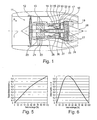
- zeigt eine schematische Darstellung eines Gasturbinentriebwerks gemäß der vorliegenden Erfindung,
- Fig. 2
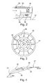
- eine Teil-Schnittansicht durch eine erfindungsgemäß zu verwendende Treibstoffdüse,
- Fig. 3
- eine stirnseitige Ansicht der in
Fig. 2 gezeigten Treibstoffdüse, - Fig. 4
- eine Definition der Kenngrößen eines Profils eines Strömungsleitelements,
- Fig. 5
- eine graphische Darstellung der Skelettlinienwinkel über die Sehnenlänge,
- Fig. 6
- eine schematische Darstellung der Dickenverteilung über die Sehnenlänge,
- Fig. 7
- Beispiele der sich erfindungsgemäß ergebenden Dickenverteilungen der Profile von Strömungsleitelementen,
- Fig. 8
- eine graphische Darstellung von Skelettlinienwinkelverteilungen,
- Fig. 9
- eine erfindungsgemäße Prinzipdarstellung der Kanalkonturierung, und
- Fig. 10
- eine graphische Darstellung erfindungsgemäßer Ausgestaltungen der inneren und äußeren Kanalwandung.
- Das Gasturbinentriebwerk 10 gemäß
Fig. 1 ist ein Beispiel, bei dem die Erfindung Anwendung finden kann. Das Triebwerk 10 ist in herkömmlicher Weise ausgebildet und umfasst in Strömungsrichtung hintereinander einen Lufteinlass 11, einen in einem Gehäuse umlaufenden Fan 12, einen Mitteldruckkompressor 13, einen Hochdruckkompressor 14, eine Ringbrennkammer 15, eine Hochdruckturbine 16, eine Mitteldruckturbine 17 und eine Niederdruckturbine 18 sowie eine Abgasdüse 19, die sämtlich um eine zentrale Triebwerksachse 1 angeordnet sind. Das Bezugszeichen 28 zeigt einen Auslasskonus. - Der Mitteldruckkompressor 13 und der Hochdruckkompressor 14 umfassen jeweils mehrere Stufen, von denen jede eine in Umfangsrichtung verlaufende Anordnung fester stationärer Leitschaufeln 20 aufweist, die allgemein als Statorschaufeln bezeichnet werden und die radial nach innen vom Triebwerksgehäuse 21 in einem ringförmigen Strömungskanal durch die Kompressoren 13, 14 vorstehen. Die Kompressoren weisen weiter eine Anordnung von Kompressorlaufschaufeln 22 auf, die radial nach außen von einer drehbaren Trommel oder Scheibe 26 vorstehen, die mit Naben 27 der Hochdruckturbine 16 bzw. der Mitteldruckturbine 17 gekoppelt sind.
- Die Turbinenabschnitte 16, 17, 18 weisen ähnliche Stufen auf, umfassend eine Anordnung von festen Leitschaufeln 23, die radial nach innen vom Gehäuse 21 in den ringförmigen Strömungskanal durch die Turbinen 16, 17, 18 vorstehen, und eine nachfolgende Anordnung von Turbinenschaufeln 24, die nach außen von einer drehbaren Nabe 27 vorstehen. Die Kompressortrommel oder Kompressorscheibe 26 und die darauf angeordneten Schaufeln 22 sowie die Turbinenrotornabe 27 und die darauf angeordneten Turbinenlaufschaufeln 24 drehen sich im Betrieb um die Triebwerksachse 1.
- Aus dem Stand der Technik sind verschiedene Brennkammern, insbesondere Ringbrennkammern 15, mit unterschiedlichen Geometrien und Gestaltungsformen bekannt. Eine Ringbrennkammer 15 besteht aus einer oberen/radial äußeren 29 und einer unteren/radial inneren 30 Brennkammerwand, die zusammen einen ringförmigen Kanal bilden. Luft und Treibstoff werden der Ringbrennkammer 15 durch die Kraftstoffdüse 33 zugeführt, sowie außerdem Luft durch Kühl- bzw. Lufteinblasöffnungen an den Seitenwänden. In der Treibstoffdüse 33 bzw. in der Ringbrennkammer 15 werden Luft und Treibstoff vermischt und verbrannt. Die Luft und die Verbrennungsprodukte werden durch eine Brennkammeraustrittsdüse 32 in Richtung der Turbine 16 abgeleitet.
- Die Vormischbrenner bzw. Kraftstoffdüsen 33 in Ringbrennkammern 15 von stationären Gasturbinen oder Fluggasturbinen zeichnen sich dadurch aus, dass die Luft und der Treibstoff gezielt geleitet und gemischt werden.
Fig. 2 zeigt schematisch den Brenner/die Kraftstoffdüse für eine Ringbrennkammer 15. Luft und Treibstoff werden durch mehrere Kanäle 34 geführt, wobei die Luft mit Hilfe von Strömungsleitelementen 36 verdrallt wird, so dass Luft- und Treibstoff sich vermischen können. Die Anzahl der Luft- und Treibstoffkanäle 34 kann dabei beliebig sein. - Die Strömungsleitelemente 36 sind in die Luftkanäle 34 eingebettet, wobei die Form des Luftkanals gemäß dem Stand der Technik zylindrisch ist und seine Höhe sich über die Länge des Strömungsleitelementes nicht ändert. Das Strömungsleitelement selber dient dazu, der Luftströmung einen Drall aufzuprägen, der in der Größenordnung von 10 bis 50 Grad liegt. Dies geschieht durch eine aerodynamische Formgebung, die durch die radiale Aufstapelung von Profilschnitten der einzelnen Strömungsleitelemente erfolgt. Die Profilschnitte sind im Allgemeinen über die Kanalhöhe identisch und sowohl axial als auch in Umfangsrichtung linear, d.h. ohne axialen oder tangentialen Versatz, angeordnet.
- Ein Profilschnitt eines Strömungsleitelements 36 lässt sich wie Folgt beschreiben: Ein Profil 40 eines Strömungsleitelements 36 ist die Überlagerung einer Skelettlinie 38 entlang einer Profilsehne 39 mit einer Dickenverteilung entlang der Profilsehne. Diese Definitionen erfolgen dimensionslos, um sie universell anwendbar zu machen. Dabei ist die Definition der Dickenverteilung dadurch gekennzeichnet, dass sie die Dicke entlang der Profilsehne 39 als Bruchteil der maximalen Dicke wiedergibt, siehe
Fig. 5 und 6 . Die Definition der Skelettlinie 38 ist derart, dass der lokale Winkel der Skelettlinie 38 in dimensionsloser Form definiert wird. Das erfolgt mit Gleichung 1 und zwar so, dass der jeweilige Wert α an einer Position I entlang der Profilsehne 38, die die Vorderkante 41 und die Hinterkante 42 des Profils 40 verbindet (sieheFig. 4 ), aus dem dort tatsächlich vorliegenden Winkel der Skelettlinie αi sowie der Neigung der Skelettlinie 38 an Vorderkante 41 bzw. an der Hinterkante 42 gegenüber der Horizontalen (BIA und BOA, sieheFig. 4 ) gebildet wird.
- Im Rahmen der Erfindung ergeben sich zwei Dickenverteilungen, die mit einer Schar von Skelettlinienverteilungen kombiniert, ein jeweils erfindungsgemäßes Profil für das Strömungsleitelement 36 (Drallelement) ergeben.
- Die beiden Dickenverteilungen sind in
Fig. 7 dargestellt und sind gemäß Gleichung 2 bzw. Gleichung 3 definiert. Die Darstellung erfolgt entlang der dimensionslosen Sehnenlänge eines beliebigen Profilschnitts. Die Definition beinhaltet dabei die Koordinate x, die von 0 bis 1 entlang der Sehne mit der dimensionslosen Länge 1 definiert ist, wobei 0 an der Vorderkante liegt und 1 an der Hinterkante (sieheFig. 4 ).

- Die Schar der Skelettlinienwinkelverteilungen ist in
Fig. 8 dargestellt. Jede Verteilung zwischen den beiden Grenzkurven ist dabei gültig, die Grenzkurven sind dabei durch Gleichungen 4 (untere) bzw. 5 (obere) definiert.

- Kombiniert ergeben sich dann entsprechende Profile. Die gezeigten Profile kombinieren die Dickenverteilung gemäß Gleichung 2 mit der Skelettlinienwinkelverteilung der unteren bzw. oberen Grenzkurve bei einem Eintrittswinkel BIA von 0 Grad und einem Austrittswinkel BOA von 45 Grad.
- Eine solche Profilform wird nun erfindungsgemäß auf alle Profilschnitte entlang der Kanalhöhe angewendet, die Auffädelung kann beliebig in axialer und Umfangsrichtung erfolgen. Idealerweise wird die beschriebene Profilierung mit einer entsprechenden Kanalkontur kombiniert.
- In Abhängigkeit von der Dickenverteilung wird erfindungsgemäß die Kanalkontur der radial inneren 43 und der radial äußeren 44 Kanalwand angepasst. Daher gibt es zu jeder der beiden erfindungsgemäßen Dickenverteilungen auch eine korrespondierende Kanalform.
- Die erfindungsgemäße Lösung basiert darauf, dass die Strömungsleitelemente 36 (Drallelemente) durch ihre Anzahl und ihre Dicke den Kanalquerschnitt verengen. Diese Verengung wird erfindungsgemäß mit einer entsprechenden Kanalwandkonturierung verringert bzw. aufgehoben. Da die Verengung lokal durch den Verlauf der Dickenverteilung bestimmt wird, muss auch die Kanalkontur, d.h. die Form der inneren und äußeren Wand und die durch diese in Kombination mit der Profilverblockung entstehende durchströmbare Fläche angepasst werden. Die radiale Koordinate der inneren bzw. äußeren Kanalwand wird korrespondierend mit der Dickenverteilung entlang der Sehne angepasst und zwar so, dass ein gewünschter Flächenverlauf durch Variation des Kanalwandradius entlang der Sehne erzielt wird, wobei die Kanalwände stromab und an der Hinterkante sowie stromauf und an der Vorderkante nicht modifiziert werden.
- In Gleichung 6 und Gleichung 7 ist die Kanalform definiert. Dabei ergibt sich eine Gleichung für die radiale Koordinate der inneren Kanalwand Ri (Gleichung 6) und eine für die der äußeren Kanalwand Ra (Gleichung 7) entlang der Sehnenlänge. Als Parameter benötigt man den Faktor N, der eine beliebige Zahl zwischen 1 und der Anzahl der Strömungsleitelemente 36 (Drallelemente) annehmen kann, die Position x, die die Position entlang der Profilsehne beschreibt und zwischen 0 und 1 (Vorder- und Hinterkante) definiert ist, die Dicke d abgeleitet aus der Dickenverteilung an der Position x und die radiale Koordinate (Position) der inneren R0i bzw. äußeren Wand R0a an der Vorderkante, siehe dazu
Fig. 9 .

- Die
Fig. 10 zeigt beispielhafte Ausbildungen für die beiden Dickenverteilungen gemäß Gleichung 2 und 3 sowie für verschiedene Werte für N. - Die erfindungsgemäße Ausgestaltung des Vormischbrenners kann sowohl bei Ringbrennkammern als auch bei einzelnen Brennkammern verwendet werden. Weiterhin kann die Erfindung auch bei anderen Drallerzeugern in Strömungskanälen Anwendung finden.
-
- 1
- Triebwerksachse
- 10
- Gasturbinentriebwerk
- 11
- Lufteinlass
- 12
- im Gehäuse umlaufender Fan
- 13
- Mittelkompressor
- 14
- Hochdruckkompressor
- 15
- Brennkammern
- 16
- Hochdruckturbine
- 17
- Mitteldruckturbine
- 18
- Niederdruckturbine
- 19
- Abgasdüse
- 20
- Leitschaufeln
- 21
- Triebwerksgehäuse
- 22
- Kompressorlaufschaufeln
- 23
- Leitschaufeln
- 24
- Turbinenschaufeln
- 26
- Kompressortrommel oder -scheibe
- 27
- Turbinenrotornabe
- 28
- Auslasskonus
- 29
- Radial äußere Brennkammerwand
- 30
- Radial innere Brennkammerwand
- 31
- Brennkammerkopf
- 32
- Brennkammeraustrittsdüse
- 33
- Treibstoffdüse
- 34
- Luftkanal
- 35
- Treibstoffkanal
- 36
- Strömungsleitelement/Drallelement
- 37
- Brennermittelachse
- 38
- Skelettlinie
- 39
- Profilsehne
- 40
- Profil
- 41
- Vorderkante
- 42
- Hinterkante
- 43
- Radial innere Kanalwandung
- 44
- Radial äußere Kanalwandung
- 45
- Konkave ringförmige Ausnehmung (radial innen)
- 46
- Konkave ringförmige Ausnehmung (radial außen)
Claims (4)
- Vormischbrenner einer Brennkammer (15) einer Gasturbine, mit zumindest einem, eine radial äußere (29) und eine radial innere (30), bezogen auf eine Brennermittelachse (37), umfassenden ringförmigen Kanal (34) zur Zuführung von Luft und Treibstoff, sowie mit zumindest einem in dem Kanal (34) angeordneten Drallerzeuger, welcher um den Umfang des Kanalquerschnitts verteilt mehrere Strömungsleitelemente (36) umfasst, dadurch gekennzeichnet, dass zumindest eine radial innere Kanalwandung (34) im Bereich der Strömungsleitelemente (36) mit einer konkaven, ringnutartigen Ausnehmung (45) versehen ist.
- Vormischbrenner nach Anspruch 1, dadurch gekennzeichnet, dass eine radial äußere (44) Kanalwandung im Bereich der Strömungsleitelemente (36) mit einer konkaven, ringnutartigen Ausnehmung (46) versehen ist.
- Vormischbrenner nach Anspruch 1 oder 2, dadurch gekennzeichnet, dass die Querschnittsfläche der radial inneren (45) und/oder radial äußeren (46) Ausnehmung gleich oder kleiner als eine in der jeweilige Querschnittsebene senkrecht zu Brennerachse (37) bestimmten Summe der Dicken der Strömungsleitelemente (36) ist.
- Vormischbrenner nach einem der Ansprüche 1 bis 3, dadurch gekennzeichnet, dass jedes Strömungsleitelement (36) ein Strömungsprofil aufweist, welches zwischen einer anströmseitigen Vorderkante (41) und einer abströmseitigen Hinterkante (42) ausgebildet ist, wobei die Vorderkante (41) und die Hinterkante (42) jeweils auf einer senkrecht zur Brennerachse (37) angeordneten Querschnittsebene angeordnet sind und dass die ringnutartige Ausnehmung (45, 46) in axialer Richtung von der Ebene der Vorderkante (41) bis zur Ebene der Hinterkante (42) ausgebildet ist.
Applications Claiming Priority (1)
| Application Number | Priority Date | Filing Date | Title |
|---|---|---|---|
| DE102012002664A DE102012002664A1 (de) | 2012-02-10 | 2012-02-10 | Gasturbinenvormischbrenner |
Publications (3)
| Publication Number | Publication Date |
|---|---|
| EP2626634A2 true EP2626634A2 (de) | 2013-08-14 |
| EP2626634A3 EP2626634A3 (de) | 2017-11-01 |
| EP2626634B1 EP2626634B1 (de) | 2019-10-09 |
Family
ID=47738974
Family Applications (1)
| Application Number | Title | Priority Date | Filing Date |
|---|---|---|---|
| EP13000607.5A Active EP2626634B1 (de) | 2012-02-10 | 2013-02-06 | Gasturbinenvormischbrenner |
Country Status (3)
| Country | Link |
|---|---|
| US (1) | US8752388B2 (de) |
| EP (1) | EP2626634B1 (de) |
| DE (1) | DE102012002664A1 (de) |
Families Citing this family (1)
| Publication number | Priority date | Publication date | Assignee | Title |
|---|---|---|---|---|
| CN112747334B (zh) * | 2021-01-20 | 2025-01-07 | 浙江浙能技术研究院有限公司 | 一种燃烧室头部结构 |
Family Cites Families (18)
| Publication number | Priority date | Publication date | Assignee | Title |
|---|---|---|---|---|
| GB710353A (en) * | 1951-06-18 | 1954-06-09 | Rolls Royce | Improvements in or relating to combustion equipment for gas-turbine engines |
| FR2235274B1 (de) * | 1973-06-28 | 1976-09-17 | Snecma | |
| DE69124154T2 (de) | 1990-07-10 | 1997-08-07 | Gen Electric | Copolyestercarbonatharzzusammensetzung |
| US5218824A (en) | 1992-06-25 | 1993-06-15 | Solar Turbines Incorporated | Low emission combustion nozzle for use with a gas turbine engine |
| DE19729246C2 (de) * | 1997-07-09 | 2001-06-28 | Deutsch Zentr Luft & Raumfahrt | Zerstäuberdüse für die Kraftstoffzerstäubung in Brennern |
| US20020162333A1 (en) * | 2001-05-02 | 2002-11-07 | Honeywell International, Inc., Law Dept. Ab2 | Partial premix dual circuit fuel injector |
| US6868676B1 (en) * | 2002-12-20 | 2005-03-22 | General Electric Company | Turbine containing system and an injector therefor |
| US8104285B2 (en) * | 2005-09-30 | 2012-01-31 | Ansaldo Energia S.P.A. | Gas turbine equipped with a gas burner and axial swirler for the burner |
| JP5023526B2 (ja) * | 2006-03-23 | 2012-09-12 | 株式会社Ihi | 燃焼器用バーナ及び燃焼方法 |
| JP4719059B2 (ja) * | 2006-04-14 | 2011-07-06 | 三菱重工業株式会社 | ガスタービンの予混合燃焼バーナー |
| FR2911667B1 (fr) * | 2007-01-23 | 2009-10-02 | Snecma Sa | Systeme d'injection de carburant a double injecteur. |
| JP4364911B2 (ja) * | 2007-02-15 | 2009-11-18 | 川崎重工業株式会社 | ガスタービンエンジンの燃焼器 |
| US8240150B2 (en) * | 2008-08-08 | 2012-08-14 | General Electric Company | Lean direct injection diffusion tip and related method |
| EP2169304A1 (de) * | 2008-09-25 | 2010-03-31 | Siemens Aktiengesellschaft | Wirbelblech |
| DE102010019772A1 (de) * | 2010-05-07 | 2011-11-10 | Rolls-Royce Deutschland Ltd & Co Kg | Magervormischbrenner eines Gasturbinentriebwerks mit einem konzentrischen, ringförmigen Zentralkörper |
| RU2531110C2 (ru) * | 2010-06-29 | 2014-10-20 | Дженерал Электрик Компани | Газотурбинная установка и установка, содержащая лопатки-форсунки (варианты) |
| EP2503241A1 (de) * | 2011-03-22 | 2012-09-26 | Siemens Aktiengesellschaft | Gasturbinenbrenner |
| US20130180248A1 (en) * | 2012-01-18 | 2013-07-18 | Nishant Govindbhai Parsania | Combustor Nozzle/Premixer with Curved Sections |
-
2012
- 2012-02-10 DE DE102012002664A patent/DE102012002664A1/de not_active Withdrawn
-
2013
- 2013-02-05 US US13/759,436 patent/US8752388B2/en active Active
- 2013-02-06 EP EP13000607.5A patent/EP2626634B1/de active Active
Non-Patent Citations (1)
| Title |
|---|
| None |
Also Published As
| Publication number | Publication date |
|---|---|
| US8752388B2 (en) | 2014-06-17 |
| EP2626634B1 (de) | 2019-10-09 |
| EP2626634A3 (de) | 2017-11-01 |
| US20130205788A1 (en) | 2013-08-15 |
| DE102012002664A1 (de) | 2013-08-14 |
Similar Documents
| Publication | Publication Date | Title |
|---|---|---|
| EP2233836B1 (de) | Drallerzeuger, Verfahren zum Vermeiden von Flammenrückschlag in einem Brenner mit wenigstens einem Drallerzeuger und Brenner | |
| EP2669474B1 (de) | Übergangskanal für eine Strömungsmaschine und Strömungsmaschine | |
| EP2362065B1 (de) | Nebenstromkanal mit Nachleitschaufelkranz in einem Turbofantriebwerk | |
| EP3239612B1 (de) | Gasturbinenbrennkammer | |
| EP2582956B1 (de) | Gasturbinenbrennkammeranordnung in axialbauweise | |
| EP2179143B1 (de) | Spaltkühlung zwischen brennkammerwand und turbinenwand einer gasturbinenanlage | |
| DE102007004394B4 (de) | Brenner zum Verbrennen eines Vorgemischs für eine Gasturbine | |
| EP2693120A2 (de) | Gasturbinenbrennkammer mit Mischluftöffnungen und Luftleitelementen in modularer Bauweise | |
| EP2918778B1 (de) | Verfahren zum auslegen einer turbine | |
| EP3290644B1 (de) | Gasturbine | |
| EP2126321A1 (de) | Gasturbine mit einem nachleitkranz und mit einem mischer | |
| EP3064706A1 (de) | Leitschaufelreihe für eine axial durchströmte Strömungsmaschine | |
| EP3306196A1 (de) | Brennkammeranordnung einer gasturbine sowie fluggasturbine | |
| EP3431708B1 (de) | Umströmungsanordnung, zugehörige strömungsmaschine und verwendung | |
| DE102012001777A1 (de) | Gasturbinenringbrennkammer | |
| EP3245451B1 (de) | Gasturbinenbrennkammer mit wandkonturierung | |
| WO2006024273A1 (de) | Rotor für ein triebwerk | |
| DE102012002465A1 (de) | Gasturbinenbrennkammer mit unsymmetrischen Kraftstoffdüsen | |
| EP2626634B1 (de) | Gasturbinenvormischbrenner | |
| EP3498972B1 (de) | Turbinenmodul für eine strömungsmaschine | |
| EP3321589A1 (de) | Treibstoffdüse einer gasturbine mit drallerzeuger | |
| DE102008062078B4 (de) | Eintrittsstufe für eine Dampfturbine | |
| CH706969A2 (de) | Verfahren zur Umfangsausrichtung von Schaufelblättern einer Turbine durch Umgestalten der abströmseitigen Schaufelblätter der Turbine. | |
| EP1288574A1 (de) | Brennkammeranordnung | |
| EP2147204B1 (de) | Gasturbogruppe sowie verfahren zur steuerung einer gasturbogruppe |
Legal Events
| Date | Code | Title | Description |
|---|---|---|---|
| PUAI | Public reference made under article 153(3) epc to a published international application that has entered the european phase |
Free format text: ORIGINAL CODE: 0009012 |
|
| AK | Designated contracting states |
Kind code of ref document: A2 Designated state(s): AL AT BE BG CH CY CZ DE DK EE ES FI FR GB GR HR HU IE IS IT LI LT LU LV MC MK MT NL NO PL PT RO RS SE SI SK SM TR |
|
| AX | Request for extension of the european patent |
Extension state: BA ME |
|
| PUAL | Search report despatched |
Free format text: ORIGINAL CODE: 0009013 |
|
| AK | Designated contracting states |
Kind code of ref document: A3 Designated state(s): AL AT BE BG CH CY CZ DE DK EE ES FI FR GB GR HR HU IE IS IT LI LT LU LV MC MK MT NL NO PL PT RO RS SE SI SK SM TR |
|
| AX | Request for extension of the european patent |
Extension state: BA ME |
|
| RIC1 | Information provided on ipc code assigned before grant |
Ipc: F23R 3/28 20060101AFI20170926BHEP Ipc: F23R 3/14 20060101ALI20170926BHEP |
|
| STAA | Information on the status of an ep patent application or granted ep patent |
Free format text: STATUS: REQUEST FOR EXAMINATION WAS MADE |
|
| 17P | Request for examination filed |
Effective date: 20180403 |
|
| RBV | Designated contracting states (corrected) |
Designated state(s): AL AT BE BG CH CY CZ DE DK EE ES FI FR GB GR HR HU IE IS IT LI LT LU LV MC MK MT NL NO PL PT RO RS SE SI SK SM TR |
|
| GRAP | Despatch of communication of intention to grant a patent |
Free format text: ORIGINAL CODE: EPIDOSNIGR1 |
|
| STAA | Information on the status of an ep patent application or granted ep patent |
Free format text: STATUS: GRANT OF PATENT IS INTENDED |
|
| INTG | Intention to grant announced |
Effective date: 20190416 |
|
| GRAS | Grant fee paid |
Free format text: ORIGINAL CODE: EPIDOSNIGR3 |
|
| GRAA | (expected) grant |
Free format text: ORIGINAL CODE: 0009210 |
|
| STAA | Information on the status of an ep patent application or granted ep patent |
Free format text: STATUS: THE PATENT HAS BEEN GRANTED |
|
| AK | Designated contracting states |
Kind code of ref document: B1 Designated state(s): AL AT BE BG CH CY CZ DE DK EE ES FI FR GB GR HR HU IE IS IT LI LT LU LV MC MK MT NL NO PL PT RO RS SE SI SK SM TR |
|
| REG | Reference to a national code |
Ref country code: GB Ref legal event code: FG4D Free format text: NOT ENGLISH |
|
| REG | Reference to a national code |
Ref country code: CH Ref legal event code: EP |
|
| REG | Reference to a national code |
Ref country code: DE Ref legal event code: R096 Ref document number: 502013013701 Country of ref document: DE |
|
| REG | Reference to a national code |
Ref country code: IE Ref legal event code: FG4D Free format text: LANGUAGE OF EP DOCUMENT: GERMAN |
|
| REG | Reference to a national code |
Ref country code: AT Ref legal event code: REF Ref document number: 1189279 Country of ref document: AT Kind code of ref document: T Effective date: 20191115 |
|
| REG | Reference to a national code |
Ref country code: NL Ref legal event code: MP Effective date: 20191009 |
|
| REG | Reference to a national code |
Ref country code: LT Ref legal event code: MG4D |
|
| PG25 | Lapsed in a contracting state [announced via postgrant information from national office to epo] |
Ref country code: NO Free format text: LAPSE BECAUSE OF FAILURE TO SUBMIT A TRANSLATION OF THE DESCRIPTION OR TO PAY THE FEE WITHIN THE PRESCRIBED TIME-LIMIT Effective date: 20200109 Ref country code: GR Free format text: LAPSE BECAUSE OF FAILURE TO SUBMIT A TRANSLATION OF THE DESCRIPTION OR TO PAY THE FEE WITHIN THE PRESCRIBED TIME-LIMIT Effective date: 20200110 Ref country code: SE Free format text: LAPSE BECAUSE OF FAILURE TO SUBMIT A TRANSLATION OF THE DESCRIPTION OR TO PAY THE FEE WITHIN THE PRESCRIBED TIME-LIMIT Effective date: 20191009 Ref country code: BG Free format text: LAPSE BECAUSE OF FAILURE TO SUBMIT A TRANSLATION OF THE DESCRIPTION OR TO PAY THE FEE WITHIN THE PRESCRIBED TIME-LIMIT Effective date: 20200109 Ref country code: FI Free format text: LAPSE BECAUSE OF FAILURE TO SUBMIT A TRANSLATION OF THE DESCRIPTION OR TO PAY THE FEE WITHIN THE PRESCRIBED TIME-LIMIT Effective date: 20191009 Ref country code: ES Free format text: LAPSE BECAUSE OF FAILURE TO SUBMIT A TRANSLATION OF THE DESCRIPTION OR TO PAY THE FEE WITHIN THE PRESCRIBED TIME-LIMIT Effective date: 20191009 Ref country code: PT Free format text: LAPSE BECAUSE OF FAILURE TO SUBMIT A TRANSLATION OF THE DESCRIPTION OR TO PAY THE FEE WITHIN THE PRESCRIBED TIME-LIMIT Effective date: 20200210 Ref country code: LV Free format text: LAPSE BECAUSE OF FAILURE TO SUBMIT A TRANSLATION OF THE DESCRIPTION OR TO PAY THE FEE WITHIN THE PRESCRIBED TIME-LIMIT Effective date: 20191009 Ref country code: NL Free format text: LAPSE BECAUSE OF FAILURE TO SUBMIT A TRANSLATION OF THE DESCRIPTION OR TO PAY THE FEE WITHIN THE PRESCRIBED TIME-LIMIT Effective date: 20191009 Ref country code: PL Free format text: LAPSE BECAUSE OF FAILURE TO SUBMIT A TRANSLATION OF THE DESCRIPTION OR TO PAY THE FEE WITHIN THE PRESCRIBED TIME-LIMIT Effective date: 20191009 Ref country code: LT Free format text: LAPSE BECAUSE OF FAILURE TO SUBMIT A TRANSLATION OF THE DESCRIPTION OR TO PAY THE FEE WITHIN THE PRESCRIBED TIME-LIMIT Effective date: 20191009 |
|
| PGFP | Annual fee paid to national office [announced via postgrant information from national office to epo] |
Ref country code: GB Payment date: 20200227 Year of fee payment: 8 |
|
| PG25 | Lapsed in a contracting state [announced via postgrant information from national office to epo] |
Ref country code: IS Free format text: LAPSE BECAUSE OF FAILURE TO SUBMIT A TRANSLATION OF THE DESCRIPTION OR TO PAY THE FEE WITHIN THE PRESCRIBED TIME-LIMIT Effective date: 20200224 Ref country code: HR Free format text: LAPSE BECAUSE OF FAILURE TO SUBMIT A TRANSLATION OF THE DESCRIPTION OR TO PAY THE FEE WITHIN THE PRESCRIBED TIME-LIMIT Effective date: 20191009 Ref country code: RS Free format text: LAPSE BECAUSE OF FAILURE TO SUBMIT A TRANSLATION OF THE DESCRIPTION OR TO PAY THE FEE WITHIN THE PRESCRIBED TIME-LIMIT Effective date: 20191009 |
|
| PG25 | Lapsed in a contracting state [announced via postgrant information from national office to epo] |
Ref country code: AL Free format text: LAPSE BECAUSE OF FAILURE TO SUBMIT A TRANSLATION OF THE DESCRIPTION OR TO PAY THE FEE WITHIN THE PRESCRIBED TIME-LIMIT Effective date: 20191009 |
|
| REG | Reference to a national code |
Ref country code: DE Ref legal event code: R097 Ref document number: 502013013701 Country of ref document: DE |
|
| PG2D | Information on lapse in contracting state deleted |
Ref country code: IS |
|
| PG25 | Lapsed in a contracting state [announced via postgrant information from national office to epo] |
Ref country code: DK Free format text: LAPSE BECAUSE OF FAILURE TO SUBMIT A TRANSLATION OF THE DESCRIPTION OR TO PAY THE FEE WITHIN THE PRESCRIBED TIME-LIMIT Effective date: 20191009 Ref country code: EE Free format text: LAPSE BECAUSE OF FAILURE TO SUBMIT A TRANSLATION OF THE DESCRIPTION OR TO PAY THE FEE WITHIN THE PRESCRIBED TIME-LIMIT Effective date: 20191009 Ref country code: CZ Free format text: LAPSE BECAUSE OF FAILURE TO SUBMIT A TRANSLATION OF THE DESCRIPTION OR TO PAY THE FEE WITHIN THE PRESCRIBED TIME-LIMIT Effective date: 20191009 Ref country code: RO Free format text: LAPSE BECAUSE OF FAILURE TO SUBMIT A TRANSLATION OF THE DESCRIPTION OR TO PAY THE FEE WITHIN THE PRESCRIBED TIME-LIMIT Effective date: 20191009 Ref country code: IS Free format text: LAPSE BECAUSE OF FAILURE TO SUBMIT A TRANSLATION OF THE DESCRIPTION OR TO PAY THE FEE WITHIN THE PRESCRIBED TIME-LIMIT Effective date: 20200209 |
|
| PLBE | No opposition filed within time limit |
Free format text: ORIGINAL CODE: 0009261 |
|
| STAA | Information on the status of an ep patent application or granted ep patent |
Free format text: STATUS: NO OPPOSITION FILED WITHIN TIME LIMIT |
|
| PG25 | Lapsed in a contracting state [announced via postgrant information from national office to epo] |
Ref country code: SM Free format text: LAPSE BECAUSE OF FAILURE TO SUBMIT A TRANSLATION OF THE DESCRIPTION OR TO PAY THE FEE WITHIN THE PRESCRIBED TIME-LIMIT Effective date: 20191009 Ref country code: IT Free format text: LAPSE BECAUSE OF FAILURE TO SUBMIT A TRANSLATION OF THE DESCRIPTION OR TO PAY THE FEE WITHIN THE PRESCRIBED TIME-LIMIT Effective date: 20191009 Ref country code: SK Free format text: LAPSE BECAUSE OF FAILURE TO SUBMIT A TRANSLATION OF THE DESCRIPTION OR TO PAY THE FEE WITHIN THE PRESCRIBED TIME-LIMIT Effective date: 20191009 |
|
| 26N | No opposition filed |
Effective date: 20200710 |
|
| REG | Reference to a national code |
Ref country code: CH Ref legal event code: PL |
|
| REG | Reference to a national code |
Ref country code: BE Ref legal event code: MM Effective date: 20200229 |
|
| PG25 | Lapsed in a contracting state [announced via postgrant information from national office to epo] |
Ref country code: LU Free format text: LAPSE BECAUSE OF NON-PAYMENT OF DUE FEES Effective date: 20200206 Ref country code: MC Free format text: LAPSE BECAUSE OF FAILURE TO SUBMIT A TRANSLATION OF THE DESCRIPTION OR TO PAY THE FEE WITHIN THE PRESCRIBED TIME-LIMIT Effective date: 20191009 |
|
| PG25 | Lapsed in a contracting state [announced via postgrant information from national office to epo] |
Ref country code: CH Free format text: LAPSE BECAUSE OF NON-PAYMENT OF DUE FEES Effective date: 20200229 Ref country code: SI Free format text: LAPSE BECAUSE OF FAILURE TO SUBMIT A TRANSLATION OF THE DESCRIPTION OR TO PAY THE FEE WITHIN THE PRESCRIBED TIME-LIMIT Effective date: 20191009 Ref country code: LI Free format text: LAPSE BECAUSE OF NON-PAYMENT OF DUE FEES Effective date: 20200229 |
|
| PG25 | Lapsed in a contracting state [announced via postgrant information from national office to epo] |
Ref country code: IE Free format text: LAPSE BECAUSE OF NON-PAYMENT OF DUE FEES Effective date: 20200206 |
|
| PG25 | Lapsed in a contracting state [announced via postgrant information from national office to epo] |
Ref country code: BE Free format text: LAPSE BECAUSE OF NON-PAYMENT OF DUE FEES Effective date: 20200229 |
|
| REG | Reference to a national code |
Ref country code: AT Ref legal event code: MM01 Ref document number: 1189279 Country of ref document: AT Kind code of ref document: T Effective date: 20200206 |
|
| PG25 | Lapsed in a contracting state [announced via postgrant information from national office to epo] |
Ref country code: AT Free format text: LAPSE BECAUSE OF NON-PAYMENT OF DUE FEES Effective date: 20200206 |
|
| GBPC | Gb: european patent ceased through non-payment of renewal fee |
Effective date: 20210206 |
|
| PG25 | Lapsed in a contracting state [announced via postgrant information from national office to epo] |
Ref country code: GB Free format text: LAPSE BECAUSE OF NON-PAYMENT OF DUE FEES Effective date: 20210206 |
|
| PG25 | Lapsed in a contracting state [announced via postgrant information from national office to epo] |
Ref country code: TR Free format text: LAPSE BECAUSE OF FAILURE TO SUBMIT A TRANSLATION OF THE DESCRIPTION OR TO PAY THE FEE WITHIN THE PRESCRIBED TIME-LIMIT Effective date: 20191009 Ref country code: MT Free format text: LAPSE BECAUSE OF FAILURE TO SUBMIT A TRANSLATION OF THE DESCRIPTION OR TO PAY THE FEE WITHIN THE PRESCRIBED TIME-LIMIT Effective date: 20191009 Ref country code: CY Free format text: LAPSE BECAUSE OF FAILURE TO SUBMIT A TRANSLATION OF THE DESCRIPTION OR TO PAY THE FEE WITHIN THE PRESCRIBED TIME-LIMIT Effective date: 20191009 |
|
| PG25 | Lapsed in a contracting state [announced via postgrant information from national office to epo] |
Ref country code: MK Free format text: LAPSE BECAUSE OF FAILURE TO SUBMIT A TRANSLATION OF THE DESCRIPTION OR TO PAY THE FEE WITHIN THE PRESCRIBED TIME-LIMIT Effective date: 20191009 |
|
| P01 | Opt-out of the competence of the unified patent court (upc) registered |
Effective date: 20230528 |
|
| PGFP | Annual fee paid to national office [announced via postgrant information from national office to epo] |
Ref country code: DE Payment date: 20240228 Year of fee payment: 12 |
|
| PGFP | Annual fee paid to national office [announced via postgrant information from national office to epo] |
Ref country code: FR Payment date: 20240226 Year of fee payment: 12 |
|
| REG | Reference to a national code |
Ref country code: DE Ref legal event code: R119 Ref document number: 502013013701 Country of ref document: DE |
|
| PG25 | Lapsed in a contracting state [announced via postgrant information from national office to epo] |
Ref country code: DE Free format text: LAPSE BECAUSE OF NON-PAYMENT OF DUE FEES Effective date: 20250902 |
|
| PG25 | Lapsed in a contracting state [announced via postgrant information from national office to epo] |
Ref country code: FR Free format text: LAPSE BECAUSE OF NON-PAYMENT OF DUE FEES Effective date: 20250228 |