EP2626581A1 - Power transmission mechanism and multi-shaft drive device - Google Patents
Power transmission mechanism and multi-shaft drive device Download PDFInfo
- Publication number
- EP2626581A1 EP2626581A1 EP11830797.4A EP11830797A EP2626581A1 EP 2626581 A1 EP2626581 A1 EP 2626581A1 EP 11830797 A EP11830797 A EP 11830797A EP 2626581 A1 EP2626581 A1 EP 2626581A1
- Authority
- EP
- European Patent Office
- Prior art keywords
- connection
- power transmission
- side transmission
- transmission mechanism
- shaft
- Prior art date
- Legal status (The legal status is an assumption and is not a legal conclusion. Google has not performed a legal analysis and makes no representation as to the accuracy of the status listed.)
- Withdrawn
Links
- 230000005540 biological transmission Effects 0.000 title claims abstract description 177
- 230000007246 mechanism Effects 0.000 title claims description 113
- 230000033001 locomotion Effects 0.000 claims description 14
- 230000002093 peripheral effect Effects 0.000 abstract description 54
- 230000009471 action Effects 0.000 description 8
- 230000009467 reduction Effects 0.000 description 6
- 230000035515 penetration Effects 0.000 description 3
- 230000004913 activation Effects 0.000 description 2
- 230000004048 modification Effects 0.000 description 2
- 238000012986 modification Methods 0.000 description 2
- 230000000694 effects Effects 0.000 description 1
- 230000006872 improvement Effects 0.000 description 1
- 230000005764 inhibitory process Effects 0.000 description 1
- 238000005728 strengthening Methods 0.000 description 1
Images


Classifications
-
- F—MECHANICAL ENGINEERING; LIGHTING; HEATING; WEAPONS; BLASTING
- F16—ENGINEERING ELEMENTS AND UNITS; GENERAL MEASURES FOR PRODUCING AND MAINTAINING EFFECTIVE FUNCTIONING OF MACHINES OR INSTALLATIONS; THERMAL INSULATION IN GENERAL
- F16H—GEARING
- F16H37/00—Combinations of mechanical gearings, not provided for in groups F16H1/00 - F16H35/00
- F16H37/02—Combinations of mechanical gearings, not provided for in groups F16H1/00 - F16H35/00 comprising essentially only toothed or friction gearings
- F16H37/06—Combinations of mechanical gearings, not provided for in groups F16H1/00 - F16H35/00 comprising essentially only toothed or friction gearings with a plurality of driving or driven shafts; with arrangements for dividing torque between two or more intermediate shafts
- F16H37/065—Combinations of mechanical gearings, not provided for in groups F16H1/00 - F16H35/00 comprising essentially only toothed or friction gearings with a plurality of driving or driven shafts; with arrangements for dividing torque between two or more intermediate shafts with a plurality of driving or driven shafts
-
- B—PERFORMING OPERATIONS; TRANSPORTING
- B60—VEHICLES IN GENERAL
- B60N—SEATS SPECIALLY ADAPTED FOR VEHICLES; VEHICLE PASSENGER ACCOMMODATION NOT OTHERWISE PROVIDED FOR
- B60N2/00—Seats specially adapted for vehicles; Arrangement or mounting of seats in vehicles
- B60N2/02—Seats specially adapted for vehicles; Arrangement or mounting of seats in vehicles the seat or part thereof being movable, e.g. adjustable
- B60N2/0296—Central command actuator to selectively switch on or engage one of several special purpose circuits or mechanisms
-
- F—MECHANICAL ENGINEERING; LIGHTING; HEATING; WEAPONS; BLASTING
- F16—ENGINEERING ELEMENTS AND UNITS; GENERAL MEASURES FOR PRODUCING AND MAINTAINING EFFECTIVE FUNCTIONING OF MACHINES OR INSTALLATIONS; THERMAL INSULATION IN GENERAL
- F16D—COUPLINGS FOR TRANSMITTING ROTATION; CLUTCHES; BRAKES
- F16D11/00—Clutches in which the members have interengaging parts
- F16D11/02—Clutches in which the members have interengaging parts disengaged by a contact of a part mounted on the clutch with a stationarily-mounted member
- F16D11/04—Clutches in which the members have interengaging parts disengaged by a contact of a part mounted on the clutch with a stationarily-mounted member with clutching members movable only axially
-
- F—MECHANICAL ENGINEERING; LIGHTING; HEATING; WEAPONS; BLASTING
- F16—ENGINEERING ELEMENTS AND UNITS; GENERAL MEASURES FOR PRODUCING AND MAINTAINING EFFECTIVE FUNCTIONING OF MACHINES OR INSTALLATIONS; THERMAL INSULATION IN GENERAL
- F16D—COUPLINGS FOR TRANSMITTING ROTATION; CLUTCHES; BRAKES
- F16D11/00—Clutches in which the members have interengaging parts
- F16D11/08—Clutches in which the members have interengaging parts actuated by moving a non-rotating part axially
-
- F—MECHANICAL ENGINEERING; LIGHTING; HEATING; WEAPONS; BLASTING
- F16—ENGINEERING ELEMENTS AND UNITS; GENERAL MEASURES FOR PRODUCING AND MAINTAINING EFFECTIVE FUNCTIONING OF MACHINES OR INSTALLATIONS; THERMAL INSULATION IN GENERAL
- F16D—COUPLINGS FOR TRANSMITTING ROTATION; CLUTCHES; BRAKES
- F16D11/00—Clutches in which the members have interengaging parts
- F16D11/08—Clutches in which the members have interengaging parts actuated by moving a non-rotating part axially
- F16D11/10—Clutches in which the members have interengaging parts actuated by moving a non-rotating part axially with clutching members movable only axially
-
- F—MECHANICAL ENGINEERING; LIGHTING; HEATING; WEAPONS; BLASTING
- F16—ENGINEERING ELEMENTS AND UNITS; GENERAL MEASURES FOR PRODUCING AND MAINTAINING EFFECTIVE FUNCTIONING OF MACHINES OR INSTALLATIONS; THERMAL INSULATION IN GENERAL
- F16D—COUPLINGS FOR TRANSMITTING ROTATION; CLUTCHES; BRAKES
- F16D23/00—Details of mechanically-actuated clutches not specific for one distinct type
- F16D23/12—Mechanical clutch-actuating mechanisms arranged outside the clutch as such
- F16D2023/123—Clutch actuation by cams, ramps or ball-screw mechanisms
-
- Y—GENERAL TAGGING OF NEW TECHNOLOGICAL DEVELOPMENTS; GENERAL TAGGING OF CROSS-SECTIONAL TECHNOLOGIES SPANNING OVER SEVERAL SECTIONS OF THE IPC; TECHNICAL SUBJECTS COVERED BY FORMER USPC CROSS-REFERENCE ART COLLECTIONS [XRACs] AND DIGESTS
- Y10—TECHNICAL SUBJECTS COVERED BY FORMER USPC
- Y10T—TECHNICAL SUBJECTS COVERED BY FORMER US CLASSIFICATION
- Y10T74/00—Machine element or mechanism
- Y10T74/19—Gearing
- Y10T74/19023—Plural power paths to and/or from gearing
- Y10T74/19074—Single drive plural driven
- Y10T74/19079—Parallel
- Y10T74/19088—Bevel
Definitions
- the present invention relates to a power transmission mechanism which transmits or does not transmit power to a output side transmission member (output shaft or the like), and relates to a multiple-shaft drive device using the power transmission mechanism.
- seats for vehicles there are many features having parts for which plural positions can be adjusted (for example, front-back direction slide of entire seat, up-and-down motion of seating face height, or reclining of seatback (backrest) can be adjusted) in accordance with body type or position of an occupant.
- the adjustments of these movable parts have been manually performed, but electrical seats, which are adjusted by motor drive, are provided as more useful seats.
- an electrical seat In order to drive plural movable parts independently, an electrical seat is thought of as having a structure in which one motor is connected to each of output shafts connected to the movable parts. However, the number of motors is increased. Therefore, it would be efficient to drive plural output shafts by one motor. In order to realize this, it is known that motor power is transmitted to each output shaft, which is connected to plural movable parts, via a clutch, and the clutch is connected or disconnected and each movable part is selectively driven (see Patent Document 1).
- Patent Document 1 is Japanese Unexamined Patent Application Publication No. H6-156123 .
- An object of the present invention is to provide a power transmission mechanism, which can reduce wear amount of a power transmission member (gear or the like) and can inhibit generation of strange noises, and a multiple-shaft drive device using the power transmission mechanism.
- a power transmission mechanism includes: an output side transmission member; an output side transmission member support portion which supports the output side transmission member in a condition in which the output side transmission member is rotatable and is restricted in axial direction movement; an input side transmission member which is disposed so as to be apart from the output side transmission member in axial direction of the output side transmission member; an input side transmission member support portion which supports the input side transmission member in a condition in which the input side transmission member is rotatable and is restricted in axial direction movement, and which holds a condition in which the input side transmission member is constantly connected to an input member; a connection member which is provided between the output side transmission member and the input side transmission member so as to be movable between two positions, which are a clutch connection position and a clutch disconnection position, in the axial direction; a biasing member which biases the connection member; and a transmission means which transmits rotation of the input side transmission member to the output side transmission member via the connection member when the connection member is positioned at the clutch connection
- the input side transmission member is held by the input side transmission member support portion so as to be restricted in axial direction movement and be constantly connected to the input member, and the biasing member is used for connecting the connection member to the input side transmission member.
- the biasing force of the biasing member can be relatively weak. As a result, wear amount can be reduced, and generation of strange noises can be inhibited.
- the input member and the input side transmission member may have bevel gears which engage with each other.
- the clutch connection position of the connection member may be a predetermined position shifted toward the input side transmission member
- the transmission means may be a link means and a connection means, the link means being rotatable together with the output side transmission member of the connection member and movable in an axial direction, the connection means being provided at connection portions of the connection member and the input side transmission member.
- the clutch connection position of the connection member may be a predetermined position shifted toward the output side transmission member
- the transmission means may be a link means and a connection means, the link means being rotatable together with the input side transmission member of the connection member and movable in an axial direction, the connection means being provided at connection portions of the connection member and the output side transmission member.
- connection means may be one of an engagement gear, a frictional plate, and a spline connection.
- the power transmission mechanism may further include: a selector member which moves the connection member in an axial direction and positions the connection member at one of two positions, which are the clutch connection position and the clutch disconnection position, in cooperation with the biasing member.
- a multiple-shaft drive device which transmits power of one motor selectively to plural movable mechanisms by connection or disconnection of clutch includes: a plurality of the power transmission mechanisms according to one of the first to the sixth aspects of the present invention.
- the force of the used biasing means can be weak, so that wear amount can be effectively reduced, and generation of strange noises can be effectively inhibited.
- Reference numerals 10 denotes a motor, 13 denotes an input gear (input member), 14 denotes a bevel gear, 20 denotes an output shaft (output side transmission member), 30 denotes a power transmission mechanism, 31 denotes a connection shaft (connection member), 32a denotes a leading end portion of a pin, 33 and 36 denote clutch teeth (transmission means, connection means, engagement gear), 34 and 37 denote frictional plate (transmission means, connection means), 35 denotes a bevel gear (input side transmission member), 35b denotes an inner peripheral spline (transmission means, connection means), 38b denotes an outer peripheral spline (transmission means, connection means), 40 denotes a coil spring (biasing member), 50 denotes a dial cam (selector member), 62 denotes a gear holder portion (output side transmission member support portion, input side transmission member support portion), and 70 denotes a slide cam (selector member).
- This multiple-shaft drive is desirably used for driving vehicle electrical seats.
- Reference numeral 10 in Figs. 1 and 2 denotes a motor having a rotational shaft 11.
- the motor 10 is fixed to an apparatus frame or the like (not shown in the Figures).
- a switch 15 for selection of ON/OFF and normal direction/opposite direction of rotational direction of the motor 10 is connected to the motor 10.
- a drive gear 11a composed of a spur gear is fixed at the rotational shaft 11.
- Plural (in this case, three) input gears 13 (input members) are disposed around the drive gear 11a.
- Each input gear 13 is a spur gear having a rotational shaft parallel to the rotational shaft 11.
- Bevel gears 14 are concentrically fixed on end surfaces (upper side end surfaces in Fig. 2 ) of the input gear 13. The power of the motor 10 is transmitted to each input gear 13, and in operation of the motor 10, each bevel gear 14 and each bevel gear 35 (described below) engaging with the bevel gear 14 are constantly rotated.
- a dial cam 50 (selector member) having a circular plate shape is disposed at an upper side of the motor 10 in Fig. 2 so as to be concentric with the rotational shaft 11.
- the dial cam 50 is rotatably supported by the above apparatus frame or the like via a rotational shaft 53.
- a recess 51 is formed at a predetermined position of an outer peripheral surface 52 of the dial cam 50. Both end portions of circumferential direction side of the recess 51 are formed at slope surfaces connected to a circumferential surface.
- a dial 55 having a circular plate shape is concentrically provided to the dial cam 55 via the rotational shaft 53.
- An operator for example, occupant in vehicle performs rotational operation of the dial cam 50 by rotating the dial 55.
- Power transmission mechanisms 30 are provided at positions corresponding to the three input gears 13 around the dial cam 50 so as to be disposed in an approximately radial manner with respect to the dial cam 50.
- the overall appearance of each power transmission mechanism 30 is approximately cylindrical.
- Each power transmission mechanism 30 has an output shaft 20 (output side transmission member), a connection shaft 31 (connection member), a bevel gear 35 (input side transmission member), and a coil spring 40 (biasing member).
- the output shafts 20 have a cylindrical shape and are disposed apart from the dial cam 50.
- the output shafts 20 have an axial direction extending in a direction which intersects the outer peripheral surface 52 of the dial cam 50.
- the output shafts 20 are supported by output shaft support member of the above apparatus frame or the like so as to be rotatable and be restricted in axial direction movement.
- an end portion of a torque cable (not shown in the Figures) is connected to a back end surface (end surface opposite to a dial cam 50 side) of each output shaft 20 so as to be rotatable together with the output shaft 20.
- each torque cable is connected to a movable mechanism of a vehicle electrical seat, which is a mechanism which adjusts seating face height, a reclining mechanism which adjusts an angle of seat back (backrest section), a mechanism which adjusts a front-back position of seat, or the like.
- a movable mechanism of a vehicle electrical seat which is a mechanism which adjusts seating face height, a reclining mechanism which adjusts an angle of seat back (backrest section), a mechanism which adjusts a front-back position of seat, or the like.
- An outer peripheral spline 21 is formed at a front end side (dial cam 50 side) of the each output shaft 20.
- Each outer peripheral spline 21 has many grooves and many protrusion stripes which extend in the axial direction and are formed alternately in a circumferential direction.
- An inner peripheral surface of the cylindrical connection shaft 31 is spline-connected to the outer peripheral spline 21.
- the connection shaft 31 is spline-connected to the output shaft 20, thereby being rotatable together with the output shaft 20 and slidable in the axial direction.
- a pin 32 is coaxially formed at a front end side of the connection shaft 31 so as to extend toward the dial cam 50.
- the bevel gear 35 is provided to the pin 32 so as to be relatively rotatable with respect to the pin 32 and so as not to be movable in the axial direction.
- the bevel gear 35 has a tooth face formed at the dial cam 50 side.
- the pin 32 is slidably penetrated to a center of the bevel gear 35, and the bevel gear 35 is supported by a bevel gear support portion (input side transmission member support portion) provided at the above apparatus frame or the like so as to be rotatable and be restricted in axial direction movement.
- the bevel gear 35 is held by the above bevel gear support portion such that the bevel gear 35 constantly engages with the bevel gear 14 and rotation of the bevel gear 14 is constantly transmitted to the bevel gear 35.
- the bevel gear 35 has a cylindrical portion 35a at a connection shaft 31 side, and the cylindrical portion 35a has an outer diameter equal to that of the connection shaft 31.
- the connection shaft 31 can be moved forward and backward in the axial direction so as to be connectable with respect to the bevel gear 35.
- Clutch teeth 33 and 36 (connection means, engagement gears) are formed on connection surfaces of the connection shaft 31and the bevel gear 35 which are surfaces facing each other (that is, an end surface of the connection shaft 31 and an end surface of the cylindrical portion 35a of bevel gear 35).
- the clutch teeth 33 and 36 engage with each other so as to allow the connection shaft 31and the bevel gear 35 to be connected and rotated together with each other.
- connection shaft 31 is constantly biased in a front end direction (direction directed to the bevel gear 35) by the coil spring 40, which is in a compressed condition and is disposed between a flange portion 22 and the connection shaft 31.
- the flange portion 22 is formed at a back end portion of the output shaft 20.
- the pin 32 is pressed by the outer peripheral surface 52 of the dial cam 50 against the coil spring 40.
- the connection shaft 31 moves backward and is positioned at a clutch disconnection position apart from the bevel gear 35, so that the connection shaft 31 and the bevel gear 35 are in a disconnected condition.
- connection shaft 31 is connected to the cylindrical portion 35a of the bevel gear 35 via the clutch teeth 33 and 36, and the connection shaft 31 and the bevel gear 35 are in a connected condition. In this connected condition, the rotation of the bevel gear 35 is transmitted to the connection shaft 31, and the output shaft 20 is rotated.
- connection shaft 31 to the output shaft 20 and the clutch teeth 33 and 36 of the connection shaft 31and the bevel gear 35 form a transmission means for transmitting the rotation of the bevel gear 35 to the output shaft 20 via the connection shaft 31.
- the power transmission mechanism 30 is in a condition in which the connection shaft 31 is biased by the coil spring 40 toward the dial cam 50.
- the connection shaft 31 slides with respect to the output shaft 20 in accordance with the rotation of the dial cam 50 rotated by the dial 55 such that the front end portion 32a of the pin 32 reciprocates between two positions which are a clutch disconnection position and a clutch connection position.
- the front end portion 32a of the pin 32 abuts the arc-like outer peripheral surface 52 of the dial cam 50.
- the front end portion 32a of the pin 32 enters the recess 51.
- the front end portion 32a of the pin 32 which is positioned at the clutch disconnection position, passes through the inclined surface and enters the recess 51, thereby moving to the clutch connection position.
- the dial cam 50 is further rotated therefrom, so that the front end portion 32a of the pin 32 passes through the inclined surface and abuts the outer peripheral surface 52 of the dial cam 50.
- connection shafts 31 At the clutch disconnection position, as shown by the connection shafts 31 provided to the two output shafts 20 at the right side of Fig. 1 , the outer peripheral surface 52 of the dial cam 50 presses the pin 32 against the coil spring 40, so that the connection shafts 31 moves backward to two output shafts 20.
- the connection shafts 31 are separated from the cylindrical portions 35a of the bevel gears 35 which engage with the bevel gears 14 and are rotated, and the connection shafts 31 and the bevel gears 35 are in a disconnected condition.
- the power of the motor 10 is only transmitted to the bevel gears 35 via the bevel gears 14, and the bevel gears 35 rotates idly around the pin 32. Therefore, the output shafts 20 are not rotated, and the torque cables are not activated.
- the dial cam 50 is rotated by the dial 55, and the recess 51 faces the pin 32.
- the pin 32 at the left side of Fig. 1 is in this condition.
- the front end portion 32a of the pin 32 enters the recess 51 through the inclined surface, and the connection shaft 31 moves to the clutch connection position.
- the connection shaft 31 is connected to the cylindrical portion 35a of the bevel gear 35 via the clutch teeth 33 and 36, and the connection shaft 31 and the bevel gear 35 are in a connected condition.
- the connection shaft 31 and the bevel gear 35 are connected, the rotation of the rotated bevel gear 35 is transmitted to the connection shaft 31, the output shaft 20 is rotated, and the torque cable is rotated and activated.
- the actions of the multiple-shaft drive device are explained above.
- the dial cam 50 is rotated, and the recess 51 is faced by the pin 32 of the power transmission mechanism 30 having the output shaft 20 to be activated.
- this output shaft 20 can be activated, and the above respective movable mechanisms of a vehicle electrical seat are selectively driven.
- the action directions of movable mechanisms can be changed by changing the rotational direction of the motor 10 by the switch 15.
- the switch 15 may be separately provided as described above, the switch 15 is provided at the dial 55, so that steps of selection of the output shaft 20 to be activated and activation of the output shaft 20 by the activation of the motor 10 can be smoothly performed by successive operations. Thus, this case is desirable.
- connection means are not limited thereto.
- frictional plates 34 and 37 may form the surfaces of the connection means.
- the coil spring 40 which biases the connection shaft 31 toward dial cam 50, is provided around the output shaft 20
- the compressed coil spring 40 may be provided at the insides of the output shaft 20 and the connection shaft 31.
- the number of the power transmission mechanisms 30 disposed around the dial cam 50 is freely selected depending on the above movable mechanisms, and the number of the recesses 51 is also freely selected.
- the angle and the direction of the power transmission mechanism 30 provided to face the dial cam 50 are freely selected insofar as connection and disconnection of the connection shaft 31 and the bevel gear 35 can be performed. In this manner, the angle and the direction thereof are changed, so that freedom of layout increases. In this case, for example, even in a small space, the power transmission mechanism 30 can be provided.
- Figs. 5 to 9 show a multiple-shaft drive device of the first embodiment.
- Reference numeral 10 in Figs. 5 and 7 denotes a motor.
- a rotational shaft 11 extending in a vertical direction projects upward from an upper end portion of the motor 10.
- a case 60 having an approximately triangular shape as seen in planar view is fixed at the upper end portion of the motor 10.
- the case 60 opens upward, and a cover (not shown in the Figures) is provided so as to cover an opening of the case 60 and so as to be removable.
- a switch (not show in the Figures) for selection of ON/OFF and normal direction/opposite direction of rotational direction of the motor 10 is connected to the motor 10.
- the rotational shaft 11 of the motor 10 penetrates a bottom portion 61 of the case 60, and a drive gear 11a is fixed at the rotational shaft 11 projecting in the case 60.
- Input gears 13 engaging with the drive gear 11a are disposed at positions corresponding to respective vertexes of the triangular shape in the case 60.
- Bevel gears 14 are integrally formed on upper surfaces of the input gears 13
- a dial cam 50 having an approximately circular plate shape is rotatably supported at a center in the case 60.
- An operational member (not shown in the Figures) is fixed at a center of the dial cam 50 via a rotational shaft 53 projecting upward. By operating the operational member, the dial cam 50 is rotated.
- the operational member is a dial, a lever, or the like.
- Recesses are formed at predetermined positions of an outer peripheral surface 52 of the dial cam 50.
- the recesses are formed at two positions, and the two positions are spaced 180 degrees from each other, the degrees being a circumferential direction angle.
- Both end portions of circumferential direction side of the recess 51 are formed at inclined surfaces connected to the outer peripheral surface 52.
- a gear holder portion 62 (output side transmission member support portion, input side transmission member support portion) is formed at a position corresponding to each of bevel gears 14 of the case 60.
- Each gear holder portion 62 opens to an upper side and has a split cylindrical shape which radially extends.
- a power transmission mechanism 30 is concentrically provided in each gear holder portion 62.
- the power transmission mechanism 30 includes an output shaft 20, a connection shaft 31, a bevel gear 35, and a coil spring 40, of which each has the same structure as that in the above embodiment.
- a gear holder cover portion having a split cylindrical shape is formed at the above cover so as to fit with the gear holder portion 62 of the case 60 and cover the power transmission mechanism 30.
- the output shaft 20 is rotatably supported at a back end portion (end portion at a side remote from the dial cam 50) in the gear holder portion 62 via a bearing bush 67. As shown in Figs. 5 and 8 , a fitting hole is formed at a center of a back end surface of the output shaft 20.
- the fit hole has a rectangular cross section, and an end portion of the torque cable is fitted into the fit hole 23.
- An outer peripheral spline 21 is formed at a front end side (dial cam 50 side) of the each output shaft 20.
- Each outer peripheral spline 21 has many grooves and many protrusion stripes which extend in the axial direction and are formed alternately.
- An inner peripheral spline 38 which is formed on an inner peripheral surface of the connection shaft 31, is provided outside the outer peripheral spline 21 and is spline-connected to the outer peripheral spline 21. That is, the connection shaft 31 is provided to the output shaft 20 so as not to be rotatable relatively to the output shaft 20 and so as to be slidable in an axial direction.
- a pin 32 is coaxially formed at a front end side of the connection shaft 31 so as to extend toward the dial cam 50.
- the bevel gear 35 is supported by the pin 32 so as to be relatively rotatable with respect to the pin 32.
- the output side bevel gear 35 engages with an input side bevel gear 14.
- the output side bevel gear 35 is held between a wall portion 63 and a step portion 64 via bearing bushes 65 and 66, thereby being held so as to be restricted in an axial direction movement and constantly engage with bevel gear 14.
- the wall portion 63 forms a front end portion of the gear holder portion 62.
- the step portion 64 has a reduced diameter.
- the wall portion 63 has an umbrella shape, which corresponds to a front end surface of the bevel gear 35, as seen in planar view.
- the pin 32 of the connection shaft 31 penetrates a center of the bevel gear 35 and the wall portion 63, and projects in the case 60. As shown in Fig. 9 , a penetration hole 63a for the pin 32 is formed at the wall portion 63, and the bearing bush 65 is press-fitted into the penetration hole 63a.
- the pin 32 is slidably inserted into the bearing bush 65.
- a flange portion 39 is formed at the connection shaft 31.
- a coil spring 40 in a compressed condition is provided between the flange portion 39 and a flange portion 22 of a back end portion of the output shaft 20.
- the connection shaft 31, which is slidable on the output shaft 20, is constantly biased by the coil spring 40 in a front end direction which is directed to the dial cam 50.
- a back end surface of the output shaft 20 is constantly abutted to a back end wall portion 68 of the gear holder portion 62, and the output shaft 20 is restricted in axial direction movement.
- connection shaft 31 can be moved forward and backward in the axial direction so as to be connectable with respect to the bevel gear 35.
- Clutch teeth 33 and 36 connection means, engagement gears
- connection surfaces of the connection shaft 31and the bevel gear 35 which are surfaces facing each other (that is, an end surface of the flange portion 39 of the connection shaft 31 and an end surface of the bevel gear 35).
- the clutch teeth 33 and 36 engage with each other so as to allow the connection shaft 31and the bevel gear 35 to be connected and rotated together with each other.
- the pin 32 is pressed by the outer peripheral surface 52 of the dial cam 50 against the coil spring 40.
- the connection shaft 31 moves backward and is positioned at a clutch disconnection position apart from the bevel gear 35, so that the connection shaft 31 and the bevel gear 35 are in a disconnected condition.
- the front end portion 32a of the pin 32 does not contact a bottom portion of the recess 51, and is spaced from the bottom portion of the recess 51 to form a small gap between the front end portion 32a and the bottom portion of the recess 51.
- the structure of the multiple-shaft drive device of the first embodiment is explained above.
- the front end portion 32a of the pin 32 of the connection shaft 31 slides with respect to the output shaft 20 so as to reciprocate between the two positions which are the clutch disconnection position and the clutch connection position.
- the front end portion 32a of the pin 32 of the connection shaft 31 abuts the arc-like outer peripheral surface 52 of the dial cam 50.
- the front end portion 32a of the pin 32 of the connection shaft 31 enters the recess 51.
- connection shaft 31 In a condition in which the motor 10 is activated and the input side bevel gears 14 is rotated, when the connection shaft 31 is positioned at the clutch disconnection position, as shown by the two power transmission mechanisms 30 at the right sides of Figs. 6 and 8 , the flange portions 39 of the connection shafts 31 are separated from the rotated bevel gears 35, the connection shafts 31and the bevel gears 35 are in a disconnected condition, the bevel gears 35 rotates idly around the pins 32, and the output shafts 20 are not rotated.
- dial cam 50 is rotated, as shown by the power transmission mechanism 30 at the left side of Figs.
- connection shaft 31 moves forward to the clutch connection position.
- connection shaft 31 is connected to the bevel gear 35 via the clutch teeth 33 and 36, and the connection shaft 31 and the bevel gear 35 are in a connected condition.
- the dial cam 50 is rotated in a normal direction and an opposite direction by operating the above operational member in a normal direction and an opposite direction.
- the pin 32 of the power transmission mechanism 30 enters the recess 51 of the dial cam 50.
- the power transmission mechanism 30 is selected, and the connection shaft 31 of the power transmission mechanism 30 is connected to the bevel gear 35.
- the above switch is turned ON, and the motor 10 is activated, so that the power of the motor 10 is transmitted to the output shaft 20 via the bevel gears 14 and 35 and the connection shaft 31, and the output shaft 20 is rotated.
- the torque cable which is connected to the output shaft 20 of the selected power transmission mechanism 30, is rotated and is in action.
- the rotational direction of the motor 10 is changed by the switch, so that the rotational direction of the torque cable is also changed together with the rotational direction of the output shaft 20.
- the bevel gear 35 of the power transmission mechanism 30 is held by the wall portion 63 and the step portion 64 so as to be restricted in axial direction movement and constantly engage with the bevel gear 14.
- the coil spring 40 is used so as to connect the connection shaft 31 to the bevel gear 35 and integrate them. That is, it is not necessary that the coil spring 40 bias the bevel gear 35 toward the bevel gear 14, and the coil spring 40 only has biasing force for connecting the connection shaft 31 to the bevel gear 35.
- the force of the coil spring 40 can be relatively weak. As a result, countermeasures (strengthening of members to which the force of the coil spring 40 is applied or the like) are not necessary. On the other hand, reduction in thickness and size can be realized, and reduction in weight can be realized.
- the reduction in the force of the coil spring 40 contributes to reduction in wear amount of bevel gears 14 and 35, and contributes to reduction in cost in accordance with improvement in assembling.
- the reduction in the force of the coil spring 40 enables inhibition of strange noises.
- the multiple-shaft drive device of the second embodiment is different from the first embodiment in using a slide cam 70 (selector member) instead of the dial cam 50 of the first embodiment, and is also different in the shape of the case corresponding to the slide cam 70.
- Figs. 10 and 11 are a perspective view and a plan view showing a multiple-shaft drive device of the second embodiment.
- reference numeral 80 denotes a case fixed at an upper portion of the motor 10, and an opening of the case is covered with a cover (not shown in the Figures).
- Plural gear holder portions 62 having a split cylindrical shape are formed at side surfaces (side surfaces of both sides of the X direction) of the case 80.
- two of the gear holder portions 62 are formed at the right side of Fig. 11 and one of the gear holder portions 62 is formed at the left side of Fig. 11 .
- a power transmission mechanism 30 including an output shaft 20, a connection shaft 31, a bevel gear 35, and a coil spring 40 is provided.
- the slide cam 70 is a plate-shaped member having an approximate parallelogram shape which is long in the Y direction in Fig. 11 .
- Two guide holes 75 extending in the Y direction 75 are formed at predetermined positions of slide cam 70.
- a guide projection 82 projecting from a bottom portion 81 of the case 80 is inserted into each of the guide holes 75.
- the slide cam 70 is guided by each guide projection 82, thereby being slidably supported in the Y direction in Fig. 11 .
- a side surface at the right side in Fig. 11 of both side surfaces extending in a longitudinal direction of the slide cam 70 is formed on a first cam surface 71.
- a lower side of a side surface at the left side in Fig. 11 is formed on a second cam surface 72, and a rack 76 having teeth aligned in the Y direction is formed at an upper side thereof.
- a pinion 90 which is rotatably supported by the case 80, engages with the rack 76.
- An operational member (dial, lever, or the like, not shown in the Figures) is fixed at the pinion 90 via a rotational shaft 91. The operational member is rotated and the pinion 90 is thereby rotated, so that the slide cam 70 reciprocates in the Y direction via the rack 76 in accordance with the rotational direction of the operational member.
- the two power transmission mechanisms 30 are disposed obliquely to the first cam surface 71 of the slide cam 70 so as to face the first cam surface 71, and the one power transmission mechanism 30 is disposed perpendicularly to the second cam surface 72 so as to face the second cam surface 72.
- the power transmission mechanisms 30 at the side of the first cam surface 71 are a first power transmission mechanism 30A and a second power transmission mechanism 30B, and the power transmission mechanism 30 at the side of the second cam surface 72 is a third power transmission mechanism 30C.
- Recesses 73 (recesses 73A and 73B) corresponding to the first power transmission mechanism 30A and the second power transmission mechanism 30B are formed on the first cam surface 71 of the slide cam 70.
- a notch 73C corresponding to the third power transmission mechanism 30C is formed at an end portion of the lower side of the second cam surface 72 in Fig. 11 .
- a front end portion 32a of a pin 32 of each connection shaft 31 biased by a coil spring 40 faces and elastically abuts the first cam surface 71 and the second cam surface 72.
- the pin 32 is pressed by the first cam surface 71 and the second cam surface 72 against the coil spring 40, and the connection shaft 31 moves backward and is separated from a bevel gear 35.
- the connection shaft 31 is positioned at a clutch disconnection position, and the connection shaft 31 and the bevel gear 35 are in a disconnected condition.
- the recess 73A, the recess 73B, or the notch 73C faces the front end portion 32a of the pin 32 of the power transmission mechanism 30 corresponding thereto.
- the pin 32 pressed by the cam surface 71 of the slide cam 70 enter the recess 73A or the recess 73B, or the pin 32 pressed by the cam surface 72 of the slide cam 70 moves forward along the notch 73C, thereby being in a clutch connection position.
- a flange portion 39 of the connection shaft 31 is connected to the bevel gear 35 via clutch teeth 33 and 36, and the connection shaft 31 and the bevel gear 35 are in a connected condition.
- the operational member is operated, and the slide cam 70 is moved in the Y direction of Fig. 11 , so that the pin 32 of the connection shaft 31 of the third power transmission mechanism 30C, which abutted the second cam surface 72, moves forward along the notch 73C.
- the clutch teeth 33 of the connection shaft 31 of the third power transmission mechanism 30C is connected to the clutch teeth 36 of the bevel gear 35, and the connection shaft 31 and the bevel gear 35 are in a connected condition.
- the pins 32 are pressed by the first cam surface 71, the connection shafts 31 move backward and are separated from the bevel gears 35, and the connection shafts 31 and the bevel gears 35 are in a disconnected condition.
- the pin 32 of the first power transmission mechanism 30A enters the first recess 73A, and the connection shaft 31 of the first power transmission mechanism 30A is connected to the bevel gear 35.
- the pins 32 are pressed by the cam surfaces 71 and 72, and the connection shafts 31 of the second power transmission mechanism 30B and the third power transmission mechanism 30C are separated from the bevel gears 35 and are in a disconnected condition.
- the operational member is operated in a normal direction and an opposite direction, and the slide cam 70 reciprocates in the Y direction.
- the pin 32 moves to one of the recesses 73A to 73C.
- the one power transmission mechanism 30 one of the first power transmission mechanism 30A, the second power transmission mechanism 30B, and the third power transmission mechanism 30C
- the connection shaft 31 of the power transmission mechanism 30 is connected to the bevel gear 35, and the output shaft 20 is rotated.
- the above switch is turned ON, and the motor 10 is activated, so that the power of the motor 10 is transmitted from the bevel gear 35 to the output shaft 20 via the connection shaft 31, and the output shaft 20 is rotated.
- the torque cable which is connected to the output shaft 20 of the selected power transmission mechanism 30, is rotated and is in action.
- the rotational direction of the motor 10 is changed by the switch, so that the rotational direction of the torque cable is also changed together with the rotational direction of the output shaft 20.
- the power transmission mechanisms 30 are also radially arranged overall, and the first power transmission mechanism 30A the second power transmission mechanism 30B obliquely face the first cam surface 71.
- the first power transmission mechanism 30A and the second power transmission mechanism 30B may be arranged parallel to each other so as to be perpendicular to the first cam surface 71.
- the arrangement of the power transmission mechanisms 30 with respect to the slide cam 70 is freely selected in accordance with arrangement space and other conditions.
- connection means for connecting and disconnecting the connection shaft 31 to the output side bevel gear 35
- the connection means can use various features.
- the power transmission mechanism 30 shown in Figs. 12 , 13A, and 13B uses a spline connection feature.
- a front end side (right side in Figs.13A and 13B ) of the output shaft 20 has a cylindrical shape, and inner peripheral splines 24 are formed at an inner peripheral surface of the cylindrical shape thereof.
- Outer peripheral splines 38b are formed at an outer peripheral surface of the connection shaft 31.
- the outer peripheral splines 38b of the connection shaft 31 are slidably inserted into the inner peripheral splines 24, and are spline-connected thereto.
- a pin 32 of an end portion of the connection shaft 31 slidably penetrates a pin penetration hole 35c which has a diameter smaller than the inner peripheral splines 35b.
- Front end portions of the outer peripheral splines 38b of the connection shaft 31 are worked to be tapered, thereby being smoothly inserted into the inner peripheral splines 35b of the bevel gear 35.
- the coil spring 40 in a compressed condition is provided in the output shaft 20 and the connection shaft 31.
- this power transmission mechanism 30 is provided in the gear holder portion 62 of the case 60.
- the action as shown in Fig. 13A , when the outer peripheral surface 52 of the dial cam 50 abuts the front end portion 32a of the pin 32, the pin 32 is pressed toward the output shaft 20 against the coil spring 40.
- the outer peripheral splines 38b of the connection shaft 31 are ejected and separated from the inner peripheral splines 35b of the bevel gear 35, and the connection shaft 31 is positioned at a clutch disconnection position.
- the connection shaft 31 and the bevel gear 35 are in a disconnected condition, the bevel gear 35 rotates idly around the pin 32, and the output shaft 20 is not rotated.
- connection shaft 31 is pressed toward the bevel gear 35 by the force of the coil spring 40, and the connection shaft 31 is positioned at a clutch connection position.
- the outer peripheral splines 38b of the connection shaft 31 are inserted into the inner peripheral splines 35b of the bevel gear 35,and are spline-connected thereto, thereby being in a connected condition.
- the rotation of the bevel gear 35 is transmitted to the output shaft 20 via the connection shaft 31, and the output shaft 20 is rotated.
- a step portion 31a which is connected to the pin 32 of the front end side of the connection shaft 31, abuts the inside of the bevel gear 35, and the connection shaft 31 is restricted in a forward movement position.
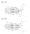
- Figs. 14A and 14B show a power transmission mechanism 30 of a third embodiment according to the present invention.
- a clutch structure is used in which the connection shaft 31 is connected or disconnected to the output shaft 20.
- connection shaft 31 of the third embodiment has outer peripheral splines 38b, is silidably inserted into inner peripheral splines 35b of the bevel gear 35, and is spline-connected to the bevel gear 35 so as to be rotatable together with the bevel gear 35.
- a flange portion 39b having a diameter, which is approximately equal to that of the output shaft 20, is formed at an intermediate portion of the connection shaft 31.
- a shaft portion 31b is slidably inserted into a guide hole 25 formed at a center of the output shaft 20.
- the connection shaft 31 slides along the bevel gear 35 and the guide hole 25, and the flange portion 39b contact the output shaft 20 or is separated therefrom.
- Clutch teeth 33b and 26 (connection means, engagement gears) engaging with each other are formed on connection surfaces of the flange portion 39b and the output shaft 20 which are surfaces facing each other.
- Ring-shaped grooves 31c and 27 are formed on the surfaces of the flange portion 39b of the connection shaft 31 and the output shaft 20 which face each other.
- the coil spring 40 in a compressed condition is provided in the grooves 31c and 27.
- the connection shaft 31 is biased toward the bevel gear 35 by the coil spring 40.
- a dial cam 56 which has a circular plate shape and has a projection 58 formed at an outer peripheral surface 57, is used as a selector member acting to the pin 32 of the connection shaft 31 Both circumferential direction sides of the projection 58 are formed at inclined surfaces connected to the outer peripheral surface 57.
- the power transmission mechanism 30 is disposed such that the pin 32 faces the outer peripheral surface 57 of the dial cam 56.
- the power transmission mechanism 30 of the third embodiment is explained above.
- the spline connection of the bevel gear 35 to the connection shaft 31 and the clutch teeth 33b and 36 of the connection shaft 31 and the output shaft 20 form a transmission means for transmitting the rotation of the bevel gear 35 to the output shaft 20 via the connection shaft 31.
- the above third embodiment uses the feature in which the power transmission mechanism 30 is activated by the projection 58 of the dial cam 56 which is the selector member of the present invention.
- This feature provides a structure opposite to the feature of the first and the second embodiment in which the power transmission mechanism is activated by the recess which is the selector member (dial cam 50 or slide cam 70).
- the present invention is not limited to these embodiments.
- any embodiments can be used.
Landscapes
- Engineering & Computer Science (AREA)
- General Engineering & Computer Science (AREA)
- Mechanical Engineering (AREA)
- Aviation & Aerospace Engineering (AREA)
- Transportation (AREA)
- Gear Transmission (AREA)
- Transmission Devices (AREA)
- Mechanical Operated Clutches (AREA)
Abstract
Force of used spring can be weak, wear amount of power transmission member (gear or the like) can be reduced, and generation of strange noises can inhibited.
When the dial cam 50 is rotated and the recess 51 of the outer peripheral surface 52 faces the front end portion 32a of the pin 32 of the connection shaft 31, the connection shaft 31, which is biased by the force of the coil spring 40, is connected to the bevel gear 35, which engages with the bevel gear 14 and is rotated, via the clutch teeth 33 and 36. Thus, the connection shaft 31 is rotated, and the output shaft 20 is rotated together with the connection shaft 31. That is, the power of the motor 10 is transmitted to the output shaft 20. Since the coil spring 40 is used for connecting the connection shaft 31 to the bevel gear 35, the force of the coil spring 40 can be reduced.
Description
- The present invention relates to a power transmission mechanism which transmits or does not transmit power to a output side transmission member (output shaft or the like), and relates to a multiple-shaft drive device using the power transmission mechanism.
- In seats for vehicles, there are many features having parts for which plural positions can be adjusted (for example, front-back direction slide of entire seat, up-and-down motion of seating face height, or reclining of seatback (backrest) can be adjusted) in accordance with body type or position of an occupant. The adjustments of these movable parts have been manually performed, but electrical seats, which are adjusted by motor drive, are provided as more useful seats.
- In order to drive plural movable parts independently, an electrical seat is thought of as having a structure in which one motor is connected to each of output shafts connected to the movable parts. However, the number of motors is increased. Therefore, it would be efficient to drive plural output shafts by one motor. In order to realize this, it is known that motor power is transmitted to each output shaft, which is connected to plural movable parts, via a clutch, and the clutch is connected or disconnected and each movable part is selectively driven (see Patent Document 1).
- Patent Document 1 is Japanese Unexamined Patent Application Publication No.
H6-156123 - In this type of power transmission mechanism, as shown in the above conventional one, a structure is used in which power is transmitted by using engagement of gears biased by biasing members (springs or the like). However, in this structure, strong biasing force is required, so that problems (wear of gears and generation of strange noises in engagement parts) may occur.
- The present invention was made in consideration of the above cases. An object of the present invention is to provide a power transmission mechanism, which can reduce wear amount of a power transmission member (gear or the like) and can inhibit generation of strange noises, and a multiple-shaft drive device using the power transmission mechanism.
- According to one aspect (claim 1) of the present invention, a power transmission mechanism includes: an output side transmission member; an output side transmission member support portion which supports the output side transmission member in a condition in which the output side transmission member is rotatable and is restricted in axial direction movement; an input side transmission member which is disposed so as to be apart from the output side transmission member in axial direction of the output side transmission member; an input side transmission member support portion which supports the input side transmission member in a condition in which the input side transmission member is rotatable and is restricted in axial direction movement, and which holds a condition in which the input side transmission member is constantly connected to an input member; a connection member which is provided between the output side transmission member and the input side transmission member so as to be movable between two positions, which are a clutch connection position and a clutch disconnection position, in the axial direction; a biasing member which biases the connection member; and a transmission means which transmits rotation of the input side transmission member to the output side transmission member via the connection member when the connection member is positioned at the clutch connection position.
- In the multiple-shaft drive device, the input side transmission member is held by the input side transmission member support portion so as to be restricted in axial direction movement and be constantly connected to the input member, and the biasing member is used for connecting the connection member to the input side transmission member. Thus, the biasing force of the biasing member can be relatively weak. As a result, wear amount can be reduced, and generation of strange noises can be inhibited.
- According to one desirable embodiment (second aspect, claim 2) of the present invention, the input member and the input side transmission member may have bevel gears which engage with each other.
- According to another desirable embodiment (third aspect, claim 3) of the present invention, the clutch connection position of the connection member may be a predetermined position shifted toward the input side transmission member, and the transmission means may be a link means and a connection means, the link means being rotatable together with the output side transmission member of the connection member and movable in an axial direction, the connection means being provided at connection portions of the connection member and the input side transmission member.
- According to another desirable embodiment (fourth aspect, claim 4) of the present invention, the clutch connection position of the connection member may be a predetermined position shifted toward the output side transmission member, and the transmission means may be a link means and a connection means, the link means being rotatable together with the input side transmission member of the connection member and movable in an axial direction, the connection means being provided at connection portions of the connection member and the output side transmission member.
- According to another desirable embodiment (fifth aspect, claim 5) of the present invention, the connection means may be one of an engagement gear, a frictional plate, and a spline connection.
- According to another desirable embodiment (sixth aspect, claim 5) of the present invention, the power transmission mechanism may further include: a selector member which moves the connection member in an axial direction and positions the connection member at one of two positions, which are the clutch connection position and the clutch disconnection position, in cooperation with the biasing member.
- According to another aspect of the present invention, a multiple-shaft drive device, which transmits power of one motor selectively to plural movable mechanisms by connection or disconnection of clutch includes: a plurality of the power transmission mechanisms according to one of the first to the sixth aspects of the present invention.
- According to the present invention, the force of the used biasing means can be weak, so that wear amount can be effectively reduced, and generation of strange noises can be effectively inhibited.
-
-
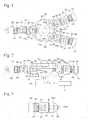
Fig. 1 is a plan view showing a basic structure of a power transmission mechanism and a multiple-shaft drive device of embodiments according to the present invention. -
Fig. 2 is a side surface view of the multiple-shaft drive device shown inFig. 1 . -
Fig. 3 is a side surface view showing another example (frictional plate) of connection means for connecting or disconnecting a connection shaft (connection member) and a bevel gear (input side transmission member) in a power transmission mechanism. -
Fig. 4 is a side surface view showing another example (frictional plate) of biasing member for biasing a connection shaft (connection member) in a direction directed to a bevel gear (input side transmission member) in a power transmission mechanism. -
Fig. 5 is a perspective view showing a multiple-shaft drive device of a first embodiment according to the present invention. -
Fig. 6 is a plan view of a multiple-shaft drive device of a first embodiment. -
Fig. 7 is a cross sectional view taken along line VII- VII inFig. 6 . -
Fig. 8 is a cross sectional view taken along line VIII- VIII inFig. 7 . -
Fig. 9 is a cross sectional view showing a power transmission mechanism of a first embodiment. -
Fig. 10 is a perspective view showing a multiple-shaft drive device of a second embodiment according to the present invention. -
Fig. 11 is a plan view of a multiple-shaft drive device of a second embodiment. -
Fig. 12 is a perspective view of a modification example of a power transmission mechanism. -
Figs. 13A and 13B are cross sectional views of the power transmission mechanism shown inFig. 12 .Fig. 13A shows a clutch disconnected condition, andFig. 13B shows a clutch connected condition. -
Figs. 14A and 14B are cross sectional views of a power transmission mechanism of a third embodiment according to the present invention.Fig. 14A shows a clutch disconnected condition, andFig. 14B shows a clutch connected condition. -
Reference numerals 10 denotes a motor, 13 denotes an input gear (input member), 14 denotes a bevel gear, 20 denotes an output shaft (output side transmission member), 30 denotes a power transmission mechanism, 31 denotes a connection shaft (connection member), 32a denotes a leading end portion of a pin, 33 and 36 denote clutch teeth (transmission means, connection means, engagement gear), 34 and 37 denote frictional plate (transmission means, connection means), 35 denotes a bevel gear (input side transmission member), 35b denotes an inner peripheral spline (transmission means, connection means), 38b denotes an outer peripheral spline (transmission means, connection means), 40 denotes a coil spring (biasing member), 50 denotes a dial cam (selector member), 62 denotes a gear holder portion (output side transmission member support portion, input side transmission member support portion), and 70 denotes a slide cam (selector member). - Embodiments of the present invention will be described with reference to the Figures hereinafter.
- First, a basic structure of a multiple-shaft drive device according to embodiments of the present invention will be described with reference to
Figs. 1 and 2 . This multiple-shaft drive is desirably used for driving vehicle electrical seats. -
Reference numeral 10 inFigs. 1 and 2 denotes a motor having arotational shaft 11. Themotor 10 is fixed to an apparatus frame or the like (not shown in the Figures). Aswitch 15 for selection of ON/OFF and normal direction/opposite direction of rotational direction of themotor 10 is connected to themotor 10. - A
drive gear 11a composed of a spur gear is fixed at therotational shaft 11. Plural (in this case, three) input gears 13 (input members) are disposed around thedrive gear 11a. Eachinput gear 13 is a spur gear having a rotational shaft parallel to therotational shaft 11. Bevel gears 14 are concentrically fixed on end surfaces (upper side end surfaces inFig. 2 ) of theinput gear 13. The power of themotor 10 is transmitted to eachinput gear 13, and in operation of themotor 10, eachbevel gear 14 and each bevel gear 35 (described below) engaging with thebevel gear 14 are constantly rotated. - A dial cam 50 (selector member) having a circular plate shape is disposed at an upper side of the
motor 10 inFig. 2 so as to be concentric with therotational shaft 11. Thedial cam 50 is rotatably supported by the above apparatus frame or the like via arotational shaft 53. Arecess 51 is formed at a predetermined position of an outerperipheral surface 52 of thedial cam 50. Both end portions of circumferential direction side of therecess 51 are formed at slope surfaces connected to a circumferential surface. Adial 55 having a circular plate shape is concentrically provided to thedial cam 55 via therotational shaft 53. An operator (for example, occupant in vehicle) performs rotational operation of thedial cam 50 by rotating thedial 55. -
Power transmission mechanisms 30 are provided at positions corresponding to the three input gears 13 around thedial cam 50 so as to be disposed in an approximately radial manner with respect to thedial cam 50. The overall appearance of eachpower transmission mechanism 30 is approximately cylindrical. Eachpower transmission mechanism 30 has an output shaft 20 (output side transmission member), a connection shaft 31 (connection member), a bevel gear 35 (input side transmission member), and a coil spring 40 (biasing member). - The
output shafts 20 have a cylindrical shape and are disposed apart from thedial cam 50. Theoutput shafts 20 have an axial direction extending in a direction which intersects the outerperipheral surface 52 of thedial cam 50. Theoutput shafts 20 are supported by output shaft support member of the above apparatus frame or the like so as to be rotatable and be restricted in axial direction movement. For example, an end portion of a torque cable (not shown in the Figures) is connected to a back end surface (end surface opposite to adial cam 50 side) of eachoutput shaft 20 so as to be rotatable together with theoutput shaft 20. For example, each torque cable is connected to a movable mechanism of a vehicle electrical seat, which is a mechanism which adjusts seating face height, a reclining mechanism which adjusts an angle of seat back (backrest section), a mechanism which adjusts a front-back position of seat, or the like. By rotation of theoutput shafts 20, the movable mechanisms are activated in accordance with rotation directions thereof. - An outer
peripheral spline 21 is formed at a front end side (dialcam 50 side) of the eachoutput shaft 20. Each outerperipheral spline 21 has many grooves and many protrusion stripes which extend in the axial direction and are formed alternately in a circumferential direction. An inner peripheral surface of thecylindrical connection shaft 31 is spline-connected to the outerperipheral spline 21. Theconnection shaft 31 is spline-connected to theoutput shaft 20, thereby being rotatable together with theoutput shaft 20 and slidable in the axial direction. Apin 32 is coaxially formed at a front end side of theconnection shaft 31 so as to extend toward thedial cam 50. Thebevel gear 35 is provided to thepin 32 so as to be relatively rotatable with respect to thepin 32 and so as not to be movable in the axial direction. Thebevel gear 35 has a tooth face formed at thedial cam 50 side. Thepin 32 is slidably penetrated to a center of thebevel gear 35, and thebevel gear 35 is supported by a bevel gear support portion (input side transmission member support portion) provided at the above apparatus frame or the like so as to be rotatable and be restricted in axial direction movement. In this support condition, thebevel gear 35 is held by the above bevel gear support portion such that thebevel gear 35 constantly engages with thebevel gear 14 and rotation of thebevel gear 14 is constantly transmitted to thebevel gear 35. - The
bevel gear 35 has acylindrical portion 35a at aconnection shaft 31 side, and thecylindrical portion 35a has an outer diameter equal to that of theconnection shaft 31. Theconnection shaft 31 can be moved forward and backward in the axial direction so as to be connectable with respect to thebevel gear 35.Clutch teeth 33 and 36 (connection means, engagement gears) are formed on connection surfaces of the connection shaft 31and thebevel gear 35 which are surfaces facing each other (that is, an end surface of theconnection shaft 31 and an end surface of thecylindrical portion 35a of bevel gear 35). Theclutch teeth bevel gear 35 to be connected and rotated together with each other. - The
connection shaft 31 is constantly biased in a front end direction (direction directed to the bevel gear 35) by thecoil spring 40, which is in a compressed condition and is disposed between aflange portion 22 and theconnection shaft 31. Theflange portion 22 is formed at a back end portion of theoutput shaft 20. When theconnection shaft 31 is moved toward thebevel gear 35 by force of thecoil spring 40 and is connected to thecylindrical portion 35a of thebevel gear 35 via theclutch teeth connection shaft 31 and thebevel gear 35 are integrally connected, and the rotation of thebevel gear 35 is transmitted to theconnection shaft 31. - A
front end portion 32a of thepin 32 of theconnection shaft 31, which is biased by thecoil spring 40, faces and constantly elastically abuts the arc-like outerperipheral surface 52 of thedial cam 50. In other words, when thefront end portion 32a of thepin 32 abuts the outerperipheral surface 52 of thedial cam 50, thepin 32 is pressed by the outerperipheral surface 52 of thedial cam 50 against thecoil spring 40. At this time, theconnection shaft 31 moves backward and is positioned at a clutch disconnection position apart from thebevel gear 35, so that theconnection shaft 31 and thebevel gear 35 are in a disconnected condition. - When the
dial cam 50 is rotated and therecess 51 faces thefront end portion 32a of thepin 32, thepin 32 of theconnection shaft 31, which was pressed by the outerperipheral surface 52 of thedial cam 50, is moved forward to thedial cam 50 by the force of thecoil spring 40, and thepin 32 is positioned at a clutch connection position. At this time, theconnection shaft 31 is connected to thecylindrical portion 35a of thebevel gear 35 via theclutch teeth connection shaft 31 and thebevel gear 35 are in a connected condition. In this connected condition, the rotation of thebevel gear 35 is transmitted to theconnection shaft 31, and theoutput shaft 20 is rotated. In this case, the spline connection of theconnection shaft 31 to theoutput shaft 20 and theclutch teeth bevel gear 35 form a transmission means for transmitting the rotation of thebevel gear 35 to theoutput shaft 20 via theconnection shaft 31. - Next, the actions of the above multiple-shaft drive device will be explained.
- The
power transmission mechanism 30 is in a condition in which theconnection shaft 31 is biased by thecoil spring 40 toward thedial cam 50. Theconnection shaft 31 slides with respect to theoutput shaft 20 in accordance with the rotation of thedial cam 50 rotated by thedial 55 such that thefront end portion 32a of thepin 32 reciprocates between two positions which are a clutch disconnection position and a clutch connection position. At the clutch disconnection position, thefront end portion 32a of thepin 32 abuts the arc-like outerperipheral surface 52 of thedial cam 50. At the clutch connection position, thefront end portion 32a of thepin 32 enters therecess 51. In accordance with the rotation of thedial cam 50, thefront end portion 32a of thepin 32, which is positioned at the clutch disconnection position, passes through the inclined surface and enters therecess 51, thereby moving to the clutch connection position. Thedial cam 50 is further rotated therefrom, so that thefront end portion 32a of thepin 32 passes through the inclined surface and abuts the outerperipheral surface 52 of thedial cam 50. - At the clutch disconnection position, as shown by the
connection shafts 31 provided to the twooutput shafts 20 at the right side ofFig. 1 , the outerperipheral surface 52 of thedial cam 50 presses thepin 32 against thecoil spring 40, so that theconnection shafts 31 moves backward to twooutput shafts 20. Thus, theconnection shafts 31 are separated from thecylindrical portions 35a of the bevel gears 35 which engage with the bevel gears 14 and are rotated, and theconnection shafts 31 and the bevel gears 35 are in a disconnected condition. In this disconnected condition, the power of themotor 10 is only transmitted to the bevel gears 35 via the bevel gears 14, and the bevel gears 35 rotates idly around thepin 32. Therefore, theoutput shafts 20 are not rotated, and the torque cables are not activated. - Next, the
dial cam 50 is rotated by thedial 55, and therecess 51 faces thepin 32. Thepin 32 at the left side ofFig. 1 is in this condition. In this case, thefront end portion 32a of thepin 32 enters therecess 51 through the inclined surface, and theconnection shaft 31 moves to the clutch connection position. At this time, theconnection shaft 31 is connected to thecylindrical portion 35a of thebevel gear 35 via theclutch teeth connection shaft 31 and thebevel gear 35 are in a connected condition. When theconnection shaft 31 and thebevel gear 35 are connected, the rotation of the rotatedbevel gear 35 is transmitted to theconnection shaft 31, theoutput shaft 20 is rotated, and the torque cable is rotated and activated. - The actions of the multiple-shaft drive device are explained above. The
dial cam 50 is rotated, and therecess 51 is faced by thepin 32 of thepower transmission mechanism 30 having theoutput shaft 20 to be activated. Thus, thisoutput shaft 20 can be activated, and the above respective movable mechanisms of a vehicle electrical seat are selectively driven. In the connected condition of theconnection shaft 31 and thebevel gear 35, the action directions of movable mechanisms can be changed by changing the rotational direction of themotor 10 by theswitch 15. Although theswitch 15 may be separately provided as described above, theswitch 15 is provided at thedial 55, so that steps of selection of theoutput shaft 20 to be activated and activation of theoutput shaft 20 by the activation of themotor 10 can be smoothly performed by successive operations. Thus, this case is desirable. - In the above embodiment, although the
clutch teeth Fig. 3 ,frictional plates 34 and 37 (surfaces formed by frictional members) may form the surfaces of the connection means. Instead of the feature in which thecoil spring 40, which biases theconnection shaft 31 towarddial cam 50, is provided around theoutput shaft 20, as shown inFig. 4 , thecompressed coil spring 40 may be provided at the insides of theoutput shaft 20 and theconnection shaft 31. - The number of the
power transmission mechanisms 30 disposed around thedial cam 50 is freely selected depending on the above movable mechanisms, and the number of therecesses 51 is also freely selected. The angle and the direction of thepower transmission mechanism 30 provided to face thedial cam 50 are freely selected insofar as connection and disconnection of theconnection shaft 31 and thebevel gear 35 can be performed. In this manner, the angle and the direction thereof are changed, so that freedom of layout increases. In this case, for example, even in a small space, thepower transmission mechanism 30 can be provided. - Next, embodiments (first to third embodiments) of the present invention, in which the above structures are specified, will be explained. In the Figures referred to in the embodiments, the same reference numerals are used for components having the same functions as those of the components shown in
Figs. 1 to 4 , and explanation thereof will be simplified or omitted. -
Figs. 5 to 9 show a multiple-shaft drive device of the first embodiment.Reference numeral 10 inFigs. 5 and7 denotes a motor. As shown inFig. 7 , in thismotor 10, arotational shaft 11 extending in a vertical direction projects upward from an upper end portion of themotor 10. Acase 60 having an approximately triangular shape as seen in planar view is fixed at the upper end portion of themotor 10. Thecase 60 opens upward, and a cover (not shown in the Figures) is provided so as to cover an opening of thecase 60 and so as to be removable. A switch (not show in the Figures) for selection of ON/OFF and normal direction/opposite direction of rotational direction of themotor 10 is connected to themotor 10. - As shown in
Fig. 7 , therotational shaft 11 of themotor 10 penetrates abottom portion 61 of thecase 60, and adrive gear 11a is fixed at therotational shaft 11 projecting in thecase 60. Input gears 13 engaging with thedrive gear 11a are disposed at positions corresponding to respective vertexes of the triangular shape in thecase 60. Bevel gears 14 are integrally formed on upper surfaces of the input gears 13 - A
dial cam 50 having an approximately circular plate shape is rotatably supported at a center in thecase 60. An operational member (not shown in the Figures) is fixed at a center of thedial cam 50 via arotational shaft 53 projecting upward. By operating the operational member, thedial cam 50 is rotated. For example, the operational member is a dial, a lever, or the like. - Recesses are formed at predetermined positions of an outer
peripheral surface 52 of thedial cam 50. In this case, the recesses are formed at two positions, and the two positions are spaced 180 degrees from each other, the degrees being a circumferential direction angle. Both end portions of circumferential direction side of therecess 51 are formed at inclined surfaces connected to the outerperipheral surface 52. - A gear holder portion 62 (output side transmission member support portion, input side transmission member support portion) is formed at a position corresponding to each of
bevel gears 14 of thecase 60. Eachgear holder portion 62 opens to an upper side and has a split cylindrical shape which radially extends. In eachgear holder portion 62, apower transmission mechanism 30 is concentrically provided. Thepower transmission mechanism 30 includes anoutput shaft 20, aconnection shaft 31, abevel gear 35, and acoil spring 40, of which each has the same structure as that in the above embodiment. A gear holder cover portion having a split cylindrical shape is formed at the above cover so as to fit with thegear holder portion 62 of thecase 60 and cover thepower transmission mechanism 30. - The
output shaft 20 is rotatably supported at a back end portion (end portion at a side remote from the dial cam 50) in thegear holder portion 62 via a bearingbush 67. As shown inFigs. 5 and8 , a fitting hole is formed at a center of a back end surface of theoutput shaft 20. The fit hole has a rectangular cross section, and an end portion of the torque cable is fitted into thefit hole 23. - An outer
peripheral spline 21 is formed at a front end side (dialcam 50 side) of the eachoutput shaft 20. Each outerperipheral spline 21 has many grooves and many protrusion stripes which extend in the axial direction and are formed alternately. An innerperipheral spline 38, which is formed on an inner peripheral surface of theconnection shaft 31, is provided outside the outerperipheral spline 21 and is spline-connected to the outerperipheral spline 21. That is, theconnection shaft 31 is provided to theoutput shaft 20 so as not to be rotatable relatively to theoutput shaft 20 and so as to be slidable in an axial direction. Apin 32 is coaxially formed at a front end side of theconnection shaft 31 so as to extend toward thedial cam 50. Thebevel gear 35 is supported by thepin 32 so as to be relatively rotatable with respect to thepin 32. The outputside bevel gear 35 engages with an inputside bevel gear 14. - The output
side bevel gear 35 is held between awall portion 63 and astep portion 64 via bearingbushes bevel gear 14. Thewall portion 63 forms a front end portion of thegear holder portion 62. Thestep portion 64 has a reduced diameter. Thewall portion 63 has an umbrella shape, which corresponds to a front end surface of thebevel gear 35, as seen in planar view. Thepin 32 of theconnection shaft 31 penetrates a center of thebevel gear 35 and thewall portion 63, and projects in thecase 60. As shown inFig. 9 , apenetration hole 63a for thepin 32 is formed at thewall portion 63, and the bearingbush 65 is press-fitted into thepenetration hole 63a. Thepin 32 is slidably inserted into the bearingbush 65. - A
flange portion 39 is formed at theconnection shaft 31. Acoil spring 40 in a compressed condition is provided between theflange portion 39 and aflange portion 22 of a back end portion of theoutput shaft 20. Theconnection shaft 31, which is slidable on theoutput shaft 20, is constantly biased by thecoil spring 40 in a front end direction which is directed to thedial cam 50. A back end surface of theoutput shaft 20 is constantly abutted to a backend wall portion 68 of thegear holder portion 62, and theoutput shaft 20 is restricted in axial direction movement. - The
connection shaft 31 can be moved forward and backward in the axial direction so as to be connectable with respect to thebevel gear 35.Clutch teeth 33 and 36 (connection means, engagement gears) are formed on connection surfaces of the connection shaft 31and thebevel gear 35 which are surfaces facing each other (that is, an end surface of theflange portion 39 of theconnection shaft 31 and an end surface of the bevel gear 35). Theclutch teeth bevel gear 35 to be connected and rotated together with each other. - A
front end portion 32a of thepin 32 of theconnection shaft 31, which is biased by thecoil spring 40 toward thedial cam 50, faces and constantly elastically abuts an arc-like outerperipheral surface 52 of thedial cam 50. When thefront end portion 32a of thepin 32 abuts the outerperipheral surface 52 of thedial cam 50, thepin 32 is pressed by the outerperipheral surface 52 of thedial cam 50 against thecoil spring 40. At this time, theconnection shaft 31 moves backward and is positioned at a clutch disconnection position apart from thebevel gear 35, so that theconnection shaft 31 and thebevel gear 35 are in a disconnected condition. - When the
dial cam 50 is rotated and therecess 51 faces thefront end portion 32a of thepin 32, thepin 32 of theconnection shaft 31, which was pressed by the outerperipheral surface 52 of thedial cam 50, is moved forward to thedial cam 50 by the force of thecoil spring 40, thepin 32 enters therecess 51 via the inclined surface, and thepin 32 is positioned at a clutch connection position. At this time, theclutch teeth 33 of theconnection shaft 31 engages with theclutch teeth 36 of thebevel gear 35, and theconnection shaft 31 and thebevel gear 35 are in a connected condition. By engagement of theclutch teeth connection shaft 31 to thedial cam 50 is inhibited. At this time, thefront end portion 32a of thepin 32 does not contact a bottom portion of therecess 51, and is spaced from the bottom portion of therecess 51 to form a small gap between thefront end portion 32a and the bottom portion of therecess 51. - The structure of the multiple-shaft drive device of the first embodiment is explained above. In the
power transmission mechanism 30 of this device, by the rotation of thedial cam 50, thefront end portion 32a of thepin 32 of theconnection shaft 31 slides with respect to theoutput shaft 20 so as to reciprocate between the two positions which are the clutch disconnection position and the clutch connection position. At the clutch disconnection position, thefront end portion 32a of thepin 32 of theconnection shaft 31 abuts the arc-like outerperipheral surface 52 of thedial cam 50. At the clutch connection position, thefront end portion 32a of thepin 32 of theconnection shaft 31 enters therecess 51. - In a condition in which the
motor 10 is activated and the input side bevel gears 14 is rotated, when theconnection shaft 31 is positioned at the clutch disconnection position, as shown by the twopower transmission mechanisms 30 at the right sides ofFigs. 6 and8 , theflange portions 39 of theconnection shafts 31 are separated from the rotatedbevel gears 35, the connection shafts 31and the bevel gears 35 are in a disconnected condition, the bevel gears 35 rotates idly around thepins 32, and theoutput shafts 20 are not rotated. Next, when thedial cam 50 is rotated, as shown by thepower transmission mechanism 30 at the left side ofFigs. 6 and8 , thefront end portion 32a of thepin 32 enters therecess 51 through the inclined surface, and theconnection shaft 31 moves forward to the clutch connection position. At this time, theconnection shaft 31 is connected to thebevel gear 35 via theclutch teeth connection shaft 31 and thebevel gear 35 are in a connected condition. - The
dial cam 50 is rotated in a normal direction and an opposite direction by operating the above operational member in a normal direction and an opposite direction. In this rotation, thepin 32 of thepower transmission mechanism 30 enters therecess 51 of thedial cam 50. At this time, thepower transmission mechanism 30 is selected, and theconnection shaft 31 of thepower transmission mechanism 30 is connected to thebevel gear 35. - In this manner, when the
transmission mechanism 30 is in a connected condition, the above switch is turned ON, and themotor 10 is activated, so that the power of themotor 10 is transmitted to theoutput shaft 20 via the bevel gears 14 and 35 and theconnection shaft 31, and theoutput shaft 20 is rotated. Thus, the torque cable, which is connected to theoutput shaft 20 of the selectedpower transmission mechanism 30, is rotated and is in action. The rotational direction of themotor 10 is changed by the switch, so that the rotational direction of the torque cable is also changed together with the rotational direction of theoutput shaft 20. - In the multiple-shaft drive device of the above first embodiment, the
bevel gear 35 of thepower transmission mechanism 30 is held by thewall portion 63 and thestep portion 64 so as to be restricted in axial direction movement and constantly engage with thebevel gear 14. Thecoil spring 40 is used so as to connect theconnection shaft 31 to thebevel gear 35 and integrate them. That is, it is not necessary that thecoil spring 40 bias thebevel gear 35 toward thebevel gear 14, and thecoil spring 40 only has biasing force for connecting theconnection shaft 31 to thebevel gear 35. - Thus, the force of the
coil spring 40 can be relatively weak. As a result, countermeasures (strengthening of members to which the force of thecoil spring 40 is applied or the like) are not necessary. On the other hand, reduction in thickness and size can be realized, and reduction in weight can be realized. The reduction in the force of thecoil spring 40 contributes to reduction in wear amount ofbevel gears coil spring 40 enables inhibition of strange noises. - Next, the second embodiment of the present invention will be explained with reference to
Figs. 10 and11 . - The multiple-shaft drive device of the second embodiment is different from the first embodiment in using a slide cam 70 (selector member) instead of the
dial cam 50 of the first embodiment, and is also different in the shape of the case corresponding to theslide cam 70. -
Figs. 10 and11 are a perspective view and a plan view showing a multiple-shaft drive device of the second embodiment. InFigs. 10 and11 ,reference numeral 80 denotes a case fixed at an upper portion of themotor 10, and an opening of the case is covered with a cover (not shown in the Figures). Pluralgear holder portions 62 having a split cylindrical shape are formed at side surfaces (side surfaces of both sides of the X direction) of thecase 80. In this case, two of thegear holder portions 62 are formed at the right side ofFig. 11 and one of thegear holder portions 62 is formed at the left side ofFig. 11 . In eachgear holder portion 62, apower transmission mechanism 30 including anoutput shaft 20, aconnection shaft 31, abevel gear 35, and acoil spring 40 is provided. - The
slide cam 70 is a plate-shaped member having an approximate parallelogram shape which is long in the Y direction inFig. 11 . Two guide holes 75 extending in theY direction 75 are formed at predetermined positions ofslide cam 70. Aguide projection 82 projecting from abottom portion 81 of thecase 80 is inserted into each of the guide holes 75. Theslide cam 70 is guided by eachguide projection 82, thereby being slidably supported in the Y direction inFig. 11 . - A side surface at the right side in
Fig. 11 of both side surfaces extending in a longitudinal direction of theslide cam 70 is formed on afirst cam surface 71. A lower side of a side surface at the left side inFig. 11 is formed on asecond cam surface 72, and arack 76 having teeth aligned in the Y direction is formed at an upper side thereof. Apinion 90, which is rotatably supported by thecase 80, engages with therack 76. An operational member (dial, lever, or the like, not shown in the Figures) is fixed at thepinion 90 via arotational shaft 91. The operational member is rotated and thepinion 90 is thereby rotated, so that theslide cam 70 reciprocates in the Y direction via therack 76 in accordance with the rotational direction of the operational member. - The two
power transmission mechanisms 30 are disposed obliquely to thefirst cam surface 71 of theslide cam 70 so as to face thefirst cam surface 71, and the onepower transmission mechanism 30 is disposed perpendicularly to thesecond cam surface 72 so as to face thesecond cam surface 72. In this embodiment, thepower transmission mechanisms 30 at the side of thefirst cam surface 71 are a firstpower transmission mechanism 30A and a secondpower transmission mechanism 30B, and thepower transmission mechanism 30 at the side of thesecond cam surface 72 is a thirdpower transmission mechanism 30C. - Recesses 73 (
recesses power transmission mechanism 30A and the secondpower transmission mechanism 30B are formed on thefirst cam surface 71 of theslide cam 70. Anotch 73C corresponding to the thirdpower transmission mechanism 30C is formed at an end portion of the lower side of thesecond cam surface 72 inFig. 11 . - In each of the power transmission mechanisms 30 (the first
power transmission mechanism 30A, the secondpower transmission mechanism 30B the thirdpower transmission mechanism 30C), afront end portion 32a of apin 32 of eachconnection shaft 31 biased by acoil spring 40 faces and elastically abuts thefirst cam surface 71 and thesecond cam surface 72. When thefront end portion 32a of thepin 32 abuts each of thefirst cam surface 71 and thesecond cam surface 72, thepin 32 is pressed by thefirst cam surface 71 and thesecond cam surface 72 against thecoil spring 40, and theconnection shaft 31 moves backward and is separated from abevel gear 35. In this case, theconnection shaft 31 is positioned at a clutch disconnection position, and theconnection shaft 31 and thebevel gear 35 are in a disconnected condition. - When the
slide cam 70 is operated by the operational member so as to move in the Y direction, therecess 73A, therecess 73B, or thenotch 73C faces thefront end portion 32a of thepin 32 of thepower transmission mechanism 30 corresponding thereto. Thus, thepin 32 pressed by thecam surface 71 of theslide cam 70 enter therecess 73A or therecess 73B, or thepin 32 pressed by thecam surface 72 of theslide cam 70 moves forward along thenotch 73C, thereby being in a clutch connection position. At this time, aflange portion 39 of theconnection shaft 31 is connected to thebevel gear 35 viaclutch teeth connection shaft 31 and thebevel gear 35 are in a connected condition. - More specific actions of the second embodiment will be explained hereinafter.
- As shown in
Figs. 10 and11 , the operational member is operated, and theslide cam 70 is moved in the Y direction ofFig. 11 , so that thepin 32 of theconnection shaft 31 of the thirdpower transmission mechanism 30C, which abutted thesecond cam surface 72, moves forward along thenotch 73C. At this time, theclutch teeth 33 of theconnection shaft 31 of the thirdpower transmission mechanism 30C is connected to theclutch teeth 36 of thebevel gear 35, and theconnection shaft 31 and thebevel gear 35 are in a connected condition. On the other hand, in the other power transmission mechanisms (the firstpower transmission mechanism 30A and the secondpower transmission mechanism 30B), thepins 32 are pressed by thefirst cam surface 71, theconnection shafts 31 move backward and are separated from the bevel gears 35, and theconnection shafts 31 and the bevel gears 35 are in a disconnected condition. - When the
slide cam 70 is moved by a predetermined distance in the Y2 direction (lower side) inFig. 11 from this condition, thepin 32 of the secondpower transmission mechanism 30B enters thesecond recess 73B, and theconnection shaft 31 of the secondpower transmission mechanism 30B is connected to thebevel gear 35. At this time, in the other power transmission mechanisms (the firstpower transmission mechanism 30A and the thirdpower transmission mechanism 30C), thepins 32 are pressed by the cam surfaces 71 and 72, and theconnection shafts 31 of the firstpower transmission mechanism 30A and the thirdpower transmission mechanism 30C are separated from the bevel gears 35 and are in a disconnected condition. - When the
slide cam 70 is further moved by a predetermined distance in the Y2 direction, thepin 32 of the firstpower transmission mechanism 30A enters thefirst recess 73A, and theconnection shaft 31 of the firstpower transmission mechanism 30A is connected to thebevel gear 35. At this time, in the other power transmission mechanisms (the secondpower transmission mechanism 30B and the thirdpower transmission mechanism 30C), thepins 32 are pressed by the cam surfaces 71 and 72, and theconnection shafts 31 of the secondpower transmission mechanism 30B and the thirdpower transmission mechanism 30C are separated from the bevel gears 35 and are in a disconnected condition. - The operational member is operated in a normal direction and an opposite direction, and the
slide cam 70 reciprocates in the Y direction. In the reciprocating of theslide cam 70, thepin 32 moves to one of therecesses 73A to 73C. At this time, as described above, the one power transmission mechanism 30 (one of the firstpower transmission mechanism 30A, the secondpower transmission mechanism 30B, and the thirdpower transmission mechanism 30C) is selected, theconnection shaft 31 of thepower transmission mechanism 30 is connected to thebevel gear 35, and theoutput shaft 20 is rotated. - In this manner, when the
transmission mechanism 30 is in a connected condition, the above switch is turned ON, and themotor 10 is activated, so that the power of themotor 10 is transmitted from thebevel gear 35 to theoutput shaft 20 via theconnection shaft 31, and theoutput shaft 20 is rotated. Thus, the torque cable, which is connected to theoutput shaft 20 of the selectedpower transmission mechanism 30, is rotated and is in action. The rotational direction of themotor 10 is changed by the switch, so that the rotational direction of the torque cable is also changed together with the rotational direction of theoutput shaft 20. - In the second embodiment, the
power transmission mechanisms 30 are also radially arranged overall, and the firstpower transmission mechanism 30A the secondpower transmission mechanism 30B obliquely face thefirst cam surface 71. Alternatively, the firstpower transmission mechanism 30A and the secondpower transmission mechanism 30B may be arranged parallel to each other so as to be perpendicular to thefirst cam surface 71. The arrangement of thepower transmission mechanisms 30 with respect to theslide cam 70 is freely selected in accordance with arrangement space and other conditions. - In the above first and second embodiments, although the
clutch teeth connection shaft 31 to the outputside bevel gear 35, the connection means can use various features. For example, thepower transmission mechanism 30 shown inFigs. 12 ,13A, and 13B uses a spline connection feature. - In this
power transmission mechanism 30, a front end side (right side inFigs.13A and 13B ) of theoutput shaft 20 has a cylindrical shape, and innerperipheral splines 24 are formed at an inner peripheral surface of the cylindrical shape thereof. Outerperipheral splines 38b are formed at an outer peripheral surface of theconnection shaft 31. The outerperipheral splines 38b of theconnection shaft 31 are slidably inserted into the innerperipheral splines 24, and are spline-connected thereto. - A front end portion of the
connection shaft 31, which has the outerperipheral splines 38b formed thereat, is slidably inserted into the innerperipheral splines 35b, which are formed at a center of thebevel gear 35, and the front end portion thereof can be spline-connected to the innerperipheral splines 35b. Apin 32 of an end portion of theconnection shaft 31 slidably penetrates apin penetration hole 35c which has a diameter smaller than the innerperipheral splines 35b. Front end portions of the outerperipheral splines 38b of theconnection shaft 31 are worked to be tapered, thereby being smoothly inserted into the innerperipheral splines 35b of thebevel gear 35. Thecoil spring 40 in a compressed condition is provided in theoutput shaft 20 and theconnection shaft 31. - For example, instead of
power transmission mechanism 30 of the first embodiment, thispower transmission mechanism 30 is provided in thegear holder portion 62 of thecase 60. In this case, regarding the action, as shown inFig. 13A , when the outerperipheral surface 52 of thedial cam 50 abuts thefront end portion 32a of thepin 32, thepin 32 is pressed toward theoutput shaft 20 against thecoil spring 40. The outerperipheral splines 38b of theconnection shaft 31 are ejected and separated from the innerperipheral splines 35b of thebevel gear 35, and theconnection shaft 31 is positioned at a clutch disconnection position. At this time, theconnection shaft 31 and thebevel gear 35 are in a disconnected condition, thebevel gear 35 rotates idly around thepin 32, and theoutput shaft 20 is not rotated. - Next, as shown in
Fig. 13B , when therecess 51 of thedial cam 50 faces thepin 32, theconnection shaft 31 is pressed toward thebevel gear 35 by the force of thecoil spring 40, and theconnection shaft 31 is positioned at a clutch connection position. At this time, the outerperipheral splines 38b of theconnection shaft 31 are inserted into the innerperipheral splines 35b of thebevel gear 35,and are spline-connected thereto, thereby being in a connected condition. At this time, the rotation of thebevel gear 35 is transmitted to theoutput shaft 20 via theconnection shaft 31, and theoutput shaft 20 is rotated. When theconnection shaft 31 moves forward, astep portion 31a, which is connected to thepin 32 of the front end side of theconnection shaft 31, abuts the inside of thebevel gear 35, and theconnection shaft 31 is restricted in a forward movement position. -
Figs. 14A and 14B show apower transmission mechanism 30 of a third embodiment according to the present invention. In this embodiment, instead of the clutch structure in which the connection member of the present invention, that is, theconnection shaft 31 is connected or disconnected to thebevel gear 35, a clutch structure is used in which theconnection shaft 31 is connected or disconnected to theoutput shaft 20. - The
connection shaft 31 of the third embodiment has outerperipheral splines 38b, is silidably inserted into innerperipheral splines 35b of thebevel gear 35, and is spline-connected to thebevel gear 35 so as to be rotatable together with thebevel gear 35. Aflange portion 39b having a diameter, which is approximately equal to that of theoutput shaft 20, is formed at an intermediate portion of theconnection shaft 31. Ashaft portion 31b is slidably inserted into aguide hole 25 formed at a center of theoutput shaft 20. Theconnection shaft 31 slides along thebevel gear 35 and theguide hole 25, and theflange portion 39b contact theoutput shaft 20 or is separated therefrom.Clutch teeth 33b and 26 (connection means, engagement gears) engaging with each other are formed on connection surfaces of theflange portion 39b and theoutput shaft 20 which are surfaces facing each other. - Ring-shaped
grooves flange portion 39b of theconnection shaft 31 and theoutput shaft 20 which face each other. Thecoil spring 40 in a compressed condition is provided in thegrooves connection shaft 31 is biased toward thebevel gear 35 by thecoil spring 40. - In the third embodiment, a
dial cam 56, which has a circular plate shape and has aprojection 58 formed at an outerperipheral surface 57, is used as a selector member acting to thepin 32 of theconnection shaft 31 Both circumferential direction sides of theprojection 58 are formed at inclined surfaces connected to the outerperipheral surface 57. Thepower transmission mechanism 30 is disposed such that thepin 32 faces the outerperipheral surface 57 of thedial cam 56. - Regarding the action of the third embodiment, when the outer
peripheral surface 57 of thedial cam 56 faces thepin 32, as shown inFig. 14A , thepin 32 is moved forward to thedial cam 56 by thecoil spring 40, and theflange portion 39b of theconnection shaft 31 is apart from theoutput shaft 20, thereby being positioned at a clutch disconnection position. In this case, theflange portion 39b abuts the back end surface of thebevel gear 35, so that thefront end portion 32a of thepin 32 does not contact the outerperipheral surface 57 of thedial cam 56, and a small is formed between thefront end portion 32a and the outerperipheral surface 57. In a case in which theconnection shaft 31 is positioned at a clutch disconnection position, even when the inputside bevel gear 35 is rotated, theconnection shaft 31 is rotated idly together with thebevel gear 35, and theoutput shaft 20 is not rotated. - Next, when the
dial cam 56 is rotated and theprojection 58 faces thefront end portion 32a of thepin 32, as shown inFig. 14B , by theprojection 58, thepin 32 is moved backward to theoutput shaft 20 against thecoil spring 40, and theconnection shaft 31 is positioned at a clutch connection position. At this time, theclutch teeth 33b of theconnection shaft 31 engages with theclutch teeth 26 of theoutput shaft 20, and theconnection shaft 31 is connected to theoutput shaft 20. At this time, the rotation of thebevel gear 35 is transmitted from theconnection shaft 31 to theoutput shaft 20 via theclutch teeth output shaft 20 is rotated. - The
power transmission mechanism 30 of the third embodiment is explained above. In this case, the spline connection of thebevel gear 35 to theconnection shaft 31 and theclutch teeth connection shaft 31 and theoutput shaft 20 form a transmission means for transmitting the rotation of thebevel gear 35 to theoutput shaft 20 via theconnection shaft 31. - The above third embodiment uses the feature in which the
power transmission mechanism 30 is activated by theprojection 58 of thedial cam 56 which is the selector member of the present invention. This feature provides a structure opposite to the feature of the first and the second embodiment in which the power transmission mechanism is activated by the recess which is the selector member (dialcam 50 or slide cam 70). - The present invention is not limited to these embodiments. Insofar as the feature can be realized in which the movement of the input side transmission member (the bevel gear 35) in the axial direction is restricted and connection and disconnection of the clutch can be performed by the movable connection member (connection shaft 31), any embodiments can be used.
Claims (7)
- A power transmission mechanism comprising:an output side transmission member;an output side transmission member support portion which supports the output side transmission member in a condition in which the output side transmission member is rotatable and is restricted in axial direction movement;an input side transmission member which is disposed so as to be apart from the output side transmission member in axial direction of the output side transmission member;an input side transmission member support portion which supports the input side transmission member in a condition in which the input side transmission member is rotatable and is restricted in axial direction movement, and which holds a condition in which the input side transmission member is constantly connected to an input member;a connection member which is provided between the output side transmission member and the input side transmission member so as to be movable between two positions, which are a clutch connection position and a clutch disconnection position, in the axial direction;a biasing member which biases the connection member; anda transmission means which transmits rotation of the input side transmission member to the output side transmission member via the connection member when the connection member is positioned at the clutch connection position.
- A power transmission mechanism according to claim 1, wherein
the input member and the input side transmission member have bevel gears which engage with each other. - A power transmission mechanism according to claim 1 or 2, wherein
the clutch connection position of the connection member is a predetermined position shifted toward the input side transmission member, and
the transmission means is a link means and a connection means, the link means being rotatable together with the output side transmission member of the connection member and movable in an axial direction, the connection means being provided at connection portions of the connection member and the input side transmission member. - A power transmission mechanism according to claim 1 or 2, wherein
the clutch connection position of the connection member is a predetermined position shifted toward the output side transmission member, and
the transmission means is a link means and a connection means, the link means being rotatable together with the input side transmission member of the connection member and movable in an axial direction, the connection means being provided at connection portions of the connection member and the output side transmission member. - A power transmission mechanism according to one of claims 1 to 4, wherein
the connection means is one of an engagement gear, a frictional plate, and a spline connection. - A power transmission mechanism according to one of claims 1 to 5, wherein the power transmission mechanism further comprising:a selector member which moves the connection member in an axial direction and positions the connection member at one of two positions, which are the clutch connection position and the clutch disconnection position, in cooperation with the biasing member.
- A multiple-shaft drive device, which transmits power of one motor selectively to plural movable mechanisms by connection or disconnection of clutch, comprising:a plurality of the power transmission mechanisms according to one of claims 1 to 5.
Applications Claiming Priority (2)
| Application Number | Priority Date | Filing Date | Title |
|---|---|---|---|
| JP2010228614 | 2010-10-08 | ||
| PCT/JP2011/073351 WO2012046868A1 (en) | 2010-10-08 | 2011-10-11 | Power transmission mechanism and multi-shaft drive device |
Publications (1)
| Publication Number | Publication Date |
|---|---|
| EP2626581A1 true EP2626581A1 (en) | 2013-08-14 |
Family
ID=45927858
Family Applications (1)
| Application Number | Title | Priority Date | Filing Date |
|---|---|---|---|
| EP11830797.4A Withdrawn EP2626581A1 (en) | 2010-10-08 | 2011-10-11 | Power transmission mechanism and multi-shaft drive device |
Country Status (6)
| Country | Link |
|---|---|
| US (1) | US20130192418A1 (en) |
| EP (1) | EP2626581A1 (en) |
| JP (1) | JPWO2012046868A1 (en) |
| KR (1) | KR101498401B1 (en) |
| CN (1) | CN103140694B (en) |
| WO (1) | WO2012046868A1 (en) |
Cited By (2)
| Publication number | Priority date | Publication date | Assignee | Title |
|---|---|---|---|---|
| EP3042802A1 (en) * | 2014-08-26 | 2016-07-13 | AMI Industries, Inc. | Multi-function seat actuator |
| DE102013216410B4 (en) | 2013-08-19 | 2022-08-25 | Zf Friedrichshafen Ag | locking device |
Families Citing this family (10)
| Publication number | Priority date | Publication date | Assignee | Title |
|---|---|---|---|---|
| DE102013200359A1 (en) * | 2013-01-14 | 2014-07-31 | Robert Bosch Gmbh | Gear box drive unit for sliding roof in motor car, has counter gear tooth portion and gear unit that are shifted together during the movement of transmission element which is provided in active connection with support element |
| US9765826B2 (en) * | 2014-08-05 | 2017-09-19 | Kanzaki Kokyukoki Mfg. Co., Ltd. | Transmission |
| WO2017004521A1 (en) * | 2015-07-01 | 2017-01-05 | Magna Seating Inc. | Single motor power seat |
| CN107307585B (en) | 2016-04-26 | 2019-12-20 | 第一传动科技股份有限公司 | Electric table foot rest and shaft coupling thereof and electric table using table foot rest |
| EP3581867B1 (en) * | 2018-06-14 | 2020-10-07 | Alite GmbH | Clinker cooler and method for operating a clinker cooler |
| CN108891310B (en) * | 2018-08-21 | 2023-10-20 | 安道拓(重庆)汽车部件有限公司 | Motor-shared automobile seat adjusting system |
| US11602337B2 (en) * | 2019-04-24 | 2023-03-14 | Nuvasive, Inc. | Transmission assembly |
| US11253243B2 (en) * | 2019-06-18 | 2022-02-22 | Nuvasive, Inc. | Tissue retraction system |
| CN114151436B (en) * | 2021-12-14 | 2025-01-17 | 上海冶成国际贸易有限公司 | Rotary locking device |
| US12571433B2 (en) * | 2024-04-16 | 2026-03-10 | Timotion Technology Co., Ltd. | Electronic control clutch structure of an actuator device |
Family Cites Families (12)
| Publication number | Priority date | Publication date | Assignee | Title |
|---|---|---|---|---|
| US2845807A (en) * | 1953-08-10 | 1958-08-05 | Hoe & Co R | Reversing drive |
| JPS59107336U (en) * | 1983-01-10 | 1984-07-19 | 株式会社クボタ | Transmission clutch structure |
| JPH02292522A (en) * | 1989-05-01 | 1990-12-04 | Kubota Corp | Transmission switching device |
| JPH0687363A (en) * | 1992-09-07 | 1994-03-29 | Mitsuba Electric Mfg Co Ltd | Drive device for vehicle 8-way power seat |
| JPH06156123A (en) | 1992-11-25 | 1994-06-03 | Mitsuba Electric Mfg Co Ltd | Device for driving movable part of power seat for vehicle |
| JPH0645138U (en) * | 1992-11-30 | 1994-06-14 | 株式会社タチエス | Geared motor |
| JP2590293Y2 (en) * | 1993-12-21 | 1999-02-10 | 日本オイルポンプ株式会社 | Semi-automatic clutch |
| JP2002031262A (en) * | 2000-07-14 | 2002-01-31 | Kawaden:Kk | Clutch device for electric valve |
| JP3765232B2 (en) * | 2000-11-16 | 2006-04-12 | 株式会社ジェイテクト | Electric power steering apparatus and gear manufacturing method used therefor |
| DE10327103B4 (en) * | 2003-06-12 | 2007-12-06 | C. Rob. Hammerstein Gmbh & Co. Kg | Reduction gear, in particular for an adjustment of a motor vehicle seat |
| JP2007198471A (en) * | 2006-01-25 | 2007-08-09 | Ntn Corp | Reversing mechanism |
| KR101028047B1 (en) * | 2010-04-01 | 2011-04-08 | 주식회사 우성아이비 | Power inverter |
-
2011
- 2011-10-11 KR KR1020137009852A patent/KR101498401B1/en not_active Expired - Fee Related
- 2011-10-11 WO PCT/JP2011/073351 patent/WO2012046868A1/en not_active Ceased
- 2011-10-11 EP EP11830797.4A patent/EP2626581A1/en not_active Withdrawn
- 2011-10-11 US US13/877,740 patent/US20130192418A1/en not_active Abandoned
- 2011-10-11 JP JP2012537784A patent/JPWO2012046868A1/en active Pending
- 2011-10-11 CN CN201180048530.8A patent/CN103140694B/en not_active Expired - Fee Related
Non-Patent Citations (1)
| Title |
|---|
| See references of WO2012046868A1 * |
Cited By (4)
| Publication number | Priority date | Publication date | Assignee | Title |
|---|---|---|---|---|
| DE102013216410B4 (en) | 2013-08-19 | 2022-08-25 | Zf Friedrichshafen Ag | locking device |
| EP3042802A1 (en) * | 2014-08-26 | 2016-07-13 | AMI Industries, Inc. | Multi-function seat actuator |
| US9758059B2 (en) | 2014-08-26 | 2017-09-12 | Ami Industries, Inc. | Multi-function seat actuator |
| US9908441B2 (en) | 2014-08-26 | 2018-03-06 | Ami Industries, Inc. | Multi-function seat actuator |
Also Published As
| Publication number | Publication date |
|---|---|
| CN103140694B (en) | 2015-06-24 |
| KR20130055690A (en) | 2013-05-28 |
| CN103140694A (en) | 2013-06-05 |
| WO2012046868A1 (en) | 2012-04-12 |
| JPWO2012046868A1 (en) | 2014-02-24 |
| KR101498401B1 (en) | 2015-03-03 |
| US20130192418A1 (en) | 2013-08-01 |
Similar Documents
| Publication | Publication Date | Title |
|---|---|---|
| US20130192418A1 (en) | Power transmission mechanism and multi-shaft drive device | |
| KR101362635B1 (en) | Multi-shaft drive device | |
| EP2650561B1 (en) | Output member and multi-shaft drive device | |
| EP2682640A1 (en) | Multi-shaft drive device | |
| US9267589B2 (en) | Multi-shaft drive device | |
| US9388891B2 (en) | Multi-shaft drive device | |
| WO2014034501A1 (en) | Power seat operation device and power seat | |
| JP2012177459A (en) | Multi-shaft driving device | |
| JPWO2010084882A1 (en) | Multi-axis drive | |
| JP2012177460A (en) | Bevel gear, power transmission mechanism, and multishaft driving device | |
| WO2011007791A1 (en) | Clutch device | |
| JP2012176734A (en) | Multiaxial driving device |
Legal Events
| Date | Code | Title | Description |
|---|---|---|---|
| PUAI | Public reference made under article 153(3) epc to a published international application that has entered the european phase |
Free format text: ORIGINAL CODE: 0009012 |
|
| 17P | Request for examination filed |
Effective date: 20130508 |
|
| AK | Designated contracting states |
Kind code of ref document: A1 Designated state(s): AL AT BE BG CH CY CZ DE DK EE ES FI FR GB GR HR HU IE IS IT LI LT LU LV MC MK MT NL NO PL PT RO RS SE SI SK SM TR |
|
| DAX | Request for extension of the european patent (deleted) | ||
| STAA | Information on the status of an ep patent application or granted ep patent |
Free format text: STATUS: THE APPLICATION HAS BEEN WITHDRAWN |
|
| 18W | Application withdrawn |
Effective date: 20150713 |