EP2626566A1 - Elektromotor - Google Patents
Elektromotor Download PDFInfo
- Publication number
- EP2626566A1 EP2626566A1 EP12154494.4A EP12154494A EP2626566A1 EP 2626566 A1 EP2626566 A1 EP 2626566A1 EP 12154494 A EP12154494 A EP 12154494A EP 2626566 A1 EP2626566 A1 EP 2626566A1
- Authority
- EP
- European Patent Office
- Prior art keywords
- motor
- housing
- motor housing
- electric motor
- electronics
- Prior art date
- Legal status (The legal status is an assumption and is not a legal conclusion. Google has not performed a legal analysis and makes no representation as to the accuracy of the status listed.)
- Granted
Links
Images

Classifications
-
- H—ELECTRICITY
- H02—GENERATION; CONVERSION OR DISTRIBUTION OF ELECTRIC POWER
- H02K—DYNAMO-ELECTRIC MACHINES
- H02K5/00—Casings; Enclosures; Supports
- H02K5/04—Casings or enclosures characterised by the shape, form or construction thereof
- H02K5/18—Casings or enclosures characterised by the shape, form or construction thereof with ribs or fins for improving heat transfer
-
- F—MECHANICAL ENGINEERING; LIGHTING; HEATING; WEAPONS; BLASTING
- F04—POSITIVE - DISPLACEMENT MACHINES FOR LIQUIDS; PUMPS FOR LIQUIDS OR ELASTIC FLUIDS
- F04D—NON-POSITIVE-DISPLACEMENT PUMPS
- F04D13/00—Pumping installations or systems
- F04D13/02—Units comprising pumps and their driving means
- F04D13/06—Units comprising pumps and their driving means the pump being electrically driven
-
- F—MECHANICAL ENGINEERING; LIGHTING; HEATING; WEAPONS; BLASTING
- F04—POSITIVE - DISPLACEMENT MACHINES FOR LIQUIDS; PUMPS FOR LIQUIDS OR ELASTIC FLUIDS
- F04D—NON-POSITIVE-DISPLACEMENT PUMPS
- F04D29/00—Details, component parts, or accessories
- F04D29/58—Cooling; Heating; Diminishing heat transfer
- F04D29/5806—Cooling the drive system
-
- F—MECHANICAL ENGINEERING; LIGHTING; HEATING; WEAPONS; BLASTING
- F04—POSITIVE - DISPLACEMENT MACHINES FOR LIQUIDS; PUMPS FOR LIQUIDS OR ELASTIC FLUIDS
- F04D—NON-POSITIVE-DISPLACEMENT PUMPS
- F04D29/00—Details, component parts, or accessories
- F04D29/58—Cooling; Heating; Diminishing heat transfer
- F04D29/5813—Cooling the control unit
-
- H—ELECTRICITY
- H02—GENERATION; CONVERSION OR DISTRIBUTION OF ELECTRIC POWER
- H02K—DYNAMO-ELECTRIC MACHINES
- H02K11/00—Structural association of dynamo-electric machines with electric components or with devices for shielding, monitoring or protection
- H02K11/30—Structural association with control circuits or drive circuits
- H02K11/33—Drive circuits, e.g. power electronics
-
- H—ELECTRICITY
- H02—GENERATION; CONVERSION OR DISTRIBUTION OF ELECTRIC POWER
- H02K—DYNAMO-ELECTRIC MACHINES
- H02K5/00—Casings; Enclosures; Supports
- H02K5/04—Casings or enclosures characterised by the shape, form or construction thereof
- H02K5/22—Auxiliary parts of casings not covered by groups H02K5/06-H02K5/20, e.g. shaped to form connection boxes or terminal boxes
-
- H—ELECTRICITY
- H02—GENERATION; CONVERSION OR DISTRIBUTION OF ELECTRIC POWER
- H02K—DYNAMO-ELECTRIC MACHINES
- H02K5/00—Casings; Enclosures; Supports
- H02K5/04—Casings or enclosures characterised by the shape, form or construction thereof
- H02K5/12—Casings or enclosures characterised by the shape, form or construction thereof specially adapted for operating in liquid or gas
- H02K5/128—Casings or enclosures characterised by the shape, form or construction thereof specially adapted for operating in liquid or gas using air-gap sleeves or air-gap discs
-
- H—ELECTRICITY
- H02—GENERATION; CONVERSION OR DISTRIBUTION OF ELECTRIC POWER
- H02K—DYNAMO-ELECTRIC MACHINES
- H02K7/00—Arrangements for handling mechanical energy structurally associated with dynamo-electric machines, e.g. structural association with mechanical driving motors or auxiliary dynamo-electric machines
- H02K7/14—Structural association with mechanical loads, e.g. with hand-held machine tools or fans
Definitions
- the invention relates to an electric motor, in particular a wet-running motor for driving a centrifugal pump having the features specified in the preamble of claim 1.
- the waste heat of the engine due to the relatively good efficiency is significantly lower than, for example, asynchronous motors or DC motors earlier design.
- the cooling requirement shifts from the motor housing to the electronics housing, especially in the case of motors controlled by the speed controller.
- the cooling fins are dimensioned smaller, but this is rather disadvantageous for the cooling of the electronics housing.
- the invention has the object to improve a generic electric motor with respect to the cooling fin education, taking into account the problem set out above.
- the electric motor according to the invention which is designed in particular as a wet-running motor for driving a centrifugal pump, has a rotor with a motor shaft, which is rotatably arranged in a motor windings having stator.
- the electric motor is equipped with a stator accommodating the motor housing, which has circumferential cooling fins for dissipating the heat generated in the engine. According to the invention, the cooling fins extend only over part of the circumference of the motor housing.
- the basic idea of the present invention is not to clone the motor housing, as is usual in the prior art, completely or at least over the areas where this is structurally possible, but to selectively leave a part of the circumference of the motor housing free of cooling ribs.
- the cooling fins are not reduced, but instead provided comparatively large cooling fins, which, however, extend only over part of the circumference of the motor housing.
- the aim and purpose of this arrangement is to create a constructive open spaces on the engine, on the other hand, in particular in the areas in which motor housing side no cooling fins are provided to create free space for cooling fins of the electronics housing.
- Such a design is particularly advantageous for electric motors which have a rotor carrying permanent magnets and generate comparatively little waste heat.
- the motor housing has a round, preferably circular cross section and is only circumferentially ribbed.
- Such an arrangement typically requires that the motor is held by means of the pump housing, that is, does not require a pedestal.
- a motor housing which is circular in cross-section, is particularly compact on the one hand and, on the other hand, has a uniform heat distribution on the inside since the stator rests on all sides at the same distance.
- the only circumferential ribbing is advantageous and reduces the axial length of the engine.
- the cooling fins on the motor housing do not extend as usual in the longitudinal direction of the motor axis but transversely to the motor axis. As a result, in particular when the motor is arranged with a horizontal motor axis, a convection current can form along the cooling ribs, which uniformly flows around the motor housing from bottom to top.
- the cooling fins extend only in a range between 190 ° - 240 ° of the circumference of the motor housing, since then a surface formed parallel to the motor axis remains, which can be used structurally for other measure than for engine cooling. It is advantageous if the cooling fin arrangement is formed so that with horizontal motor, the ribs each extend from the bottom right or left around the motor housing over an angle of 95 ° - 120 °, so that at the top of a kind free Platform remains, especially when the height of the ribs is chosen to be larger towards the outlet end than in the remaining area.
- the cooling fins of the motor housing extend not only around a part of the circumference but also beyond only a longitudinal portion of the motor housing, so that a further longitudinal portion remains, which is formed rib-free.
- a rib-free design is particularly advantageous in the region of the connection to the pump housing, since a very compact pump construction can be achieved, especially in the case of an in-line housing provided with connection flanges, the distance of the flanges or the pump housing located therebetween can be made small.
- the motor housing forms according to a further embodiment of the invention in non-ribbed peripheral area a mounting base for an electronics housing, which has power electronics for controlling the motor, typically comprises at least the power electronics of an electronic speed controller, in particular a frequency converter.
- an electronics housing which has power electronics for controlling the motor, typically comprises at least the power electronics of an electronic speed controller, in particular a frequency converter.
- the electronics housing In order to integrate in particular the cooling of the motor housing mounted on the electronics housing in the engine cooling or to ensure that a convection air flow both the motor and the electronics housing cools, it is advantageous if the electronics housing to the motor housing facing cooling fins, which are arranged in alignment with the engine-side cooling fins. Then forms an intensive convection flow, especially coming from the bottom of the motor housing and then the aligned cooling fins of the electronics housing, especially in horizontal axle assembly of the engine and overhead electronics housing. Since in modern permanent magnet motors, the heat of the engine is lower than that of the engine power electronics, such an arrangement is also advantageous insofar as the passing past the engine air is not heated enough so that they could no longer absorb heat from the cooling fins of the electronics housing.
- the motor housing and / or the electronics housing are made as a cast housing of good heat-conducting material, preferably of a light metal alloy.
- the thermal conductivity of the material should be at least 10 W / m ⁇ K at 0 ° C, preferably at least 100 W / m ⁇ K at 0 ° C, to ensure an intensive heat dissipation in this area of the engine and electronics housing.
- Fig. 1 shown Kreiselpumpenaggregot has a centrifugal pump 1 with a pump housing 2 and a rotatable therein arranged impeller 3, which sits on a shaft 4 of a subsequent to the pump housing 2 motor housing 5 of an electric motor 6.
- the electric motor 6 is a wet-running motor, ie the space in which the rotor 7 runs with the shaft 4 is filled with liquid and separated fluid-tight from the stator 9 by a gap tube 8.
- the stator 9 is seated in the circular cross-section motor housing 5, which is detachably connected by means of a flange 10 with a flange 11 of the pump housing via a clamping ring 12.
- the electric motor is a permanent magnet rotor, which is driven by an electronic speed controller, which is arranged in an electronics housing 13, which in the manner of a Terminal box is attached to the motor housing 5 and via which also the electrical connection of the motor connection takes place.
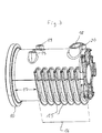
- the motor housing 5 has in this embodiment seven transverse to the motor axis 14 extending cooling fins 15, which extend in a longitudinal portion 16 over part of the outer periphery of the motor housing 5.
- the motor housing still has a longitudinal section 17, which is free of cooling ribs. It extends between the flange 10 and the electronics housing. 3
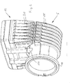
- the cooling fins 15 extend, as in particular Fig. 3 is apparent, not over the entire circumference of the motor housing, but over about 210 ° of the circumference, in the position according to the Fig. 1 and 2 from the bottom of the motor housing 5 each about 105 ° to both sides upwards.
- the height of the ribs increases from a range of about 80 ° of the circumference (starting from the bottom) to the end clearly, as in particular from Fig. 2 is apparent.
- a rib-free peripheral portion of the motor housing 5 results in the region of the otherwise provided with ribs 15 longitudinal portion 16 of the motor housing.
- the motor housing 5 near the free end of the motor has a base 18 which surrounds a slot-shaped recess in the motor housing 5 and via which the electrical line connection between the stator and the electronics housing 13 arranged above takes place.
- a base 18 Spaced apart in the rib-free region, two approximately circular base in cross-section 19 are provided which serve exclusively for fastening and are provided with a respective threaded hole.
- These three pedestals 18 and 19 serve to support the electronics housing 13 located above, which is screw-mounted in the threaded bores of the base 19 and is connected by the wide base 18 with the interior of the stator housing for the purpose of the cable bushing.
- the wide base 18 has a bulge 20, which with a threaded hole provided and is provided for screw mounting the electronics housing 13 in this area.
- the electronics housing 13, when mounted on the motor housing 5, is arranged to also have cooling fins 21 disposed transverse to the motor axis 14, which are downwardly spaced from the substantially rectangular housing spaced from the motor housing 5 in the spaced-apart area until just before the rib-free area in the longitudinal section 16 of the motor housing 5 protrude.
- These, extending from the bottom of the electronics housing to the motor housing 5 down ribs are arranged in alignment with the cooling fins 21 of the motor housing, so that in the in the Fig. 1 and 2 shown motor position a Konventionluftstrom from the bottom of the motor housing extending upward to form under the electronics housing and from there to the sides.
- the cooling fins 21 of the electronics housing 13 may be provided which are substantially higher than that of the motor housing 5 and thus form a heat sink at the bottom of the electronics housing ,
- the motor housing 5 and the electronics housing 13 are formed of metal, these are cast components, which consist of a light metal alloy and have good thermal conductivity.
Landscapes
- Engineering & Computer Science (AREA)
- Physics & Mathematics (AREA)
- Thermal Sciences (AREA)
- Mechanical Engineering (AREA)
- General Engineering & Computer Science (AREA)
- Power Engineering (AREA)
- Microelectronics & Electronic Packaging (AREA)
- Motor Or Generator Frames (AREA)
- Motor Or Generator Cooling System (AREA)
- Structures Of Non-Positive Displacement Pumps (AREA)
Abstract
Description
- Die Erfindung betrifft einen Elektromotor, insbesondere einen Nasslaufmotor zum Antrieb einer Kreiselpumpe mit den im Oberbegriff des Anspruchs 1 angegebenen Merkmalen.
- Um die im Elektromotor beim Betrieb anfallende Verlustwärme abführen zu können, zählt es zum Stand der Technik, Elektromotoren über den gesamtem Umfang ihres Motorgehäuses mit Kühlrippen zu versehen, die mehr oder weniger parallel zur Längsachse des Motors angeordnet sind und durch Konvektionskühlung die Motorwärme abführen sollen. Unterstützt wird dies häufig durch ein auf der Motorwelle sitzendes Lüfterrad, welches über eine Lüfterhaube axial Luft ansaugt und diese dann längs der Kühlrippen leitet, um auf diese Weise die Abwärme des Motors über diesen Luftstrom abzuführen.
- Mit kleiner werdender Leistungselektronik haben sich zwischenzeitlich Elektromotoren, insbesondere zum Antrieb von Kreiselpumpen, durchgesetzt, welche in dem am Elektromotor vorgesehenen Klemmenkasten, der ursprünglich ausschließlich zum elektrischen Anschluss des Motors diente, elektronische Schaltungen und insbesondere auch Leistungselektronik, typischerweise die eines elektronischen Drehzahlstellers, für den Motor beinhalten. Der Klemmenkasten bildet damit bei modernen Motoren gleichzeitig ein Elektronikgehäuse. Allerdings liegt die Abwärme solcher heutzutage verwendeten Leistungselektronik in der Größenordnung der Motorabwärme, weshalb es zum Stand der Technik zählt, nicht nur den Elektromotor selbst mit Kühlrippen zu versehen sondern auch den Klemmenkasten, also das daran befindliche Elektronikgehäuse. Dabei hat es sich bewährt, die gehäuse. Dabei hat es sich bewährt, die Kühlrippen des Elektronikgehäuses ebenfalls in Längsrichtung des Motors, also parallel zu den Längsrippen des Motors verlaufen zu lassen, um so mit dem Kühlluftstrom des Motors auch das Elektronikgehäuse zu kühlen.
- Bei modernen Permanentmagnetrotoren ist die Abwärme des Motors aufgrund des vergleichsweise guten Wirkungsgrades deutlich geringer als beispielsweise bei Asynchronmotoren oder Gleichstrommotoren früherer Bauart. Damit verlagert sich der Kühlbedarf insbesondere bei mit Drehzahlsteller gesteuerten Motoren vom Motorgehäuse zum Elektronikgehäuse hin. Dem geringeren Kühlbedarf des Motors Rechnung tragend werden die Kühlrippen kleiner dimensioniert, was jedoch für die Kühlung des Elektronikgehäuses eher nachteilig ist.
- Vor diesem Hintergrund liegt der Erfindung die Aufgabe zugrunde, einen gattungsgemäßen Elektromotor hinsichtlich der Kühlrippenausbildung unter Berücksichtigung der eingangs dargelegten Problematik zu verbessern.
- Diese Aufgabe wird gemäß der Erfindung durch einen Elektromotor mit den in Anspruch 1 angegebenen Merkmalen gelöst. Vorteilhafte Ausgestaltungen der Erfindung sind in den Unteransprüchen, der nachfolgenden Beschreibung und der Zeichnung angegeben.
- Der erfindungsgemäße Elektromotor, der insbesondere als Nasslaufmotor zum Antrieb einer Kreiselpumpe ausgebildet ist, weist einen Rotor mit Motorwelle auf, der drehbar in einem Motorwicklungen aufweisenden Stator angeordnet ist. Der Elektromotor ist mit einem den Stator aufnehmenden Motorgehäuse ausgestattet, welches umfangsseitige Kühlrippen zur Abfuhr der im Motor entstehenden Wärme aufweist. Gemäß der Erfindung erstrecken sich die Kühlrippen nur über einen Teil des Umfangs des Motorgehäuses.
- Grundgedanke der vorliegenden Erfindung ist es, das Motorgehäuse, nicht wie beim Stand der Technik üblich, vollständig oder zumindest über die Bereiche zu berippen, bei denen dies konstruktiv möglich ist, sondern gezielt einen Teil des Umfangs des Motorgehäuses kühlrippenfrei zu belassen. Es werden also die Kühlrippen nicht verkleinert, sondern stattdessen vergleichsweise große Kühlrippen vorgesehen, die sich jedoch nur über einen Teil des Umfangs des Motorgehäuses erstrecken. Ziel und Zweck dieser Anordnung ist es, zum einen konstruktive Freiräume am Motor zu schaffen, zum anderen insbesondere in den Bereichen, in denen motorgehäuseseitig keine Kühlrippen vorgesehen sind, Freiräume für Kühlrippen des Elektronikgehäuses zu schaffen. Eine solche Ausbildung ist insbesondere für Elektromotoren vorteilhaft, die einen Permanentmagnete tragenden Rotor aufweisen und vergleichsweise wenig Abwärme erzeugen. Besonders vorteilhaft ist die erfindungsgemäße Ausbildung also für Permanentmagnetmotoren, die als Nasslaufmotoren ausgebildet sind und zum Antrieb einer Kreiselpumpe bestimmt sind, da aufgrund der sich an das Motorgehäuse anschließenden Pumpengehäuses Kühlluftströme nur im Bereich des Motorgehäuses selbst geführt werden können und dies auch nur dort, wo An-und Abströmung durch das angeschlossene Pumpengehäuse nicht behindert sind.
- Gemäß einer vorteilhaften Weiterbildung der Erfindung weist das Motorgehäuse einen runden, vorzugsweise kreisrunden Querschnitt auf und ist nur umfangsseitig berippt. Eine solche Anordnung bedingt typischerweise, dass der Motor mittels des Pumpengehäuses gehalten wird, also keinen Standfuß benötigt. Ein solches im Querschnitt kreisrundes Motorgehäuse ist zum einen besonders kompakt und weist zum anderen von Innen heraus eine gleichmäßige Wärmeverteilung auf, da der Stator allseits in gleichem Abstand anliegt. Die nur umfangsseitige Berippung ist vorteilhaft und verringert die axiale Baulänge des Motors. Gemäß einer besonders vorteilhaften Ausgestaltung der Erfindung erstrecken sich die Kühlrippen am Motorgehäuse nicht wie üblich in Längsrichtung der Motorachse sondern quer zur Motorachse. Hierdurch kann sich, insbesondere bei Anordnung des Motors mit horizontaler Motorachse ein Konvektionsstrom längs der Kühlrippen ausbilden, welcher das Motorgehäuse von unten nach oben gleichmäßig umströmt.
- Besonders vorteilhaft ist es, wenn sich die Kühlrippen nur in einem Bereich zwischen 190° - 240° des Umfangs des Motorgehäuses erstrecken, da dann eine parallel zur Motorachse gebildete Fläche verbleibt, die konstruktiv für andere Maßnahme als zur Motorkühlung genutzt werden kann. Dabei ist es von Vorteil, wenn die Kühlrippenanordnung so ausgebildet ist, dass bei horizontal liegendem Motor sich die Rippen jeweils von der Unterseite rechtsherum bzw. linksherum um das Motorgehäuse über einen Winkel von 95° - 120° erstrecken, sodass an der Oberseite eine Art freie Plattform verbleibt, insbesondere wenn die Höhe der Rippen zum Auslaufende hin größer gewählt wird, als im übrigen Bereich.
- Gemäß einer vorteilhaften Ausgestaltung der Erfindung erstrecken sich die Kühlrippen des Motorgehäuses nicht nur um einen Teil des Umfangs sondern darüber hinaus auch nur über einen Längsabschnitt des Motorgehäuses, sodass ein weiterer Längsabschnitt verbleibt, der rippenfrei ausgebildet ist. Eine solche rippenfreie Ausbildung ist insbesondere im Bereich des Anschlusses an das Pumpengehäuse von Vorteil, da dadurch eine sehr kompakte Pumpenkonstruktion erzielt werden kann, insbesondere bei einem mit Anschlussflanschen versehenen Inlinegehäuse der Abstand der Flansche bzw. das dazwischen liegende Pumpengehäuse klein gewählt werden kann.
- Vorteilhaft bildet das Motorgehäuse gemäß einer weiteren Ausgestaltung der Erfindung im nicht berippten Umfangsbereich eine Montagebasis für ein Elektronikgehäuse, welches Leistungselektronik zur Steuerung des Motors aufweist, typischerweise zumindest die Leistungselektronik eines elektronischen Drehzahlstellers, insbesondere eines Frequenzumrichters umfasst. Eine solche Anordnung ist vorteilhaft, da sie zum einen einen vergleichsweise großen Freiraum für das Elektronikgehäuse bietet, zum anderen den kühlrippenfreien Bereich des Motorsgehäuses in idealer Weise konstruktiv ausnutzt.
- Um insbesondere auch die Kühlung des am Motorgehäuse montierten Elektronikgehäuses in die Motorkühlung zu integrieren bzw. dafür zu sorgen, dass ein Konvektionsluftstrom sowohl das Motor- als auch das Elektronikgehäuse kühlt, ist es von Vorteil, wenn das Elektronikgehäuse zum Motorgehäuse hin weisende Kühlrippen aufweist, welche im Flucht zu den motorseitigen Kühlrippen angeordnet sind. Dann bildet sich insbesondere bei horizontaler Achsanordnung des Motors und oben liegendem Elektronikgehäuse eine intensive Konvektionsströmung, welche zunächst von der Unterseite kommend das Motorgehäuse und dann die fluchtenden Kühlrippen des Elektronikgehäuses umstreicht. Da bei modernen Permanentmagnetmotoren die Abwärme des Motors geringer als die der Motorleistungselektronik ist, ist eine solche Anordnung auch insoweit vorteilhaft, da die am Motor vorbeistreichende Luft noch nicht soweit aufgeheizt ist, dass sie von den Kühlrippen des Elektronikgehäuses keine Wärme mehr aufnehmen könnte.
- Besonders vorteilhaft ist es, wenn das Motorgehäuse und/oder das Elektronikgehäuse als Gussgehäuse aus gut wärmeleitendem Werkstoff bestehen, vorzugsweise aus einer Leichtmetalllegierung. Dabei sollte die Wärmeleitfähigkeit des Werkstoffes mindestens 10 W/m ·K bei 0°C, bevorzugt mindestens 100 W/m·K bei 0 °C aufweisen, um eine intensive Wärmeabfuhr in diesem Bereiche vom Motor und Elektronikgehäuse zu gewährleisten.
- Die Erfindung ist nachfolgend anhand eines in der Zeichnung dargestellten Ausführungsbeispiels näher erläutert. Es zeigen:
- Fig. 1
- in stark schematisierter Längsschnittdarstellung einen Elektromotor mit daran angeschlossener Kreiselpumpe,
- Fig. 2
- in perspektivischer Darstellung das Motorgehäuse des Elektromotors gemäß
Fig. 1 mit darauf angeordnetem Elektronikgehäuse, - Fig. 3
- in perspektivischer Darstellung das Motorgehäuse ohne Elektronikgehäuse,
- Fig. 4
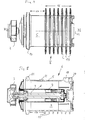
- eine Ansicht des Elektromotors von unten und
- Fig. 5
- einen Längsschnitt längs der Schnittlinie V-V in
Fig. 4 . - Das anhand von
Fig. 1 dargestellte Kreiselpumpenaggregot weist eine Kreiselpumpe 1 mit einem Pumpengehäuse 2 und einem drehbar darin angeordneten Kreiselrad 3 auf, welches auf einer Welle 4 eines an das Pumpengehäuse 2 anschließenden Motorgehäuses 5 eines Elektromotors 6 sitzt. Bei dem Elektromotor 6 handelt es sich um einen Nasslaufmotor, d. h. der Raum, in welchem der Rotor 7 mit der Welle 4 läuft, ist flüssigkeitsgefüllt und durch ein Spaltrohr 8 vom Stator 9 fluiddicht getrennt. Der Stator 9 sitzt in dem im Querschnitt kreisrunden Motorgehäuse 5, welches mittels eines Flansches 10 mit einem Flansch 11 des Pumpengehäuses über einen Spannring 12 lösbar verbunden ist. - Bei dem Elektromotor handelt es sich um einen Permanentmagnetrotor, der von einem elektronischen Drehzahlsteller angesteuert wird, der in einem Elektronikgehäuse 13 angeordnet ist, welches nach Art eines Klemmenkastens am Motorgehäuse 5 befestigt ist und über das auch die elektrische Anschlussverbindung des Motors erfolgt.
- Das Motorgehäuse 5 weist in dieser Ausführungsform sieben quer zur Motorachse 14 verlaufende Kühlrippen 15 auf, welche sich in einem Längsabschnitt 16 über einen Teil des Außenumfangs des Motorgehäuses 5 erstrecken. Darüber hinaus weist das Motorgehäuse noch einen Längsabschnitt 17 auf, welcher kühlrippenfrei ist. Er erstreckt sich zwischen dem Flansch 10 und dem Elektronikgehäuse 3.
- Die Kühlrippen 15 erstrecken sich, wie insbesondere aus
Fig. 3 ersichtlich ist, nicht über den gesamten Umfang des Motorgehäuses, sondern über etwa 210° des Umfangs, und zwar in der Stellung gemäß denFig. 1 und2 von der Unterseite des Motorgehäuses 5 jeweils um ca. 105° zu beiden Seiten nach oben. Dabei vergrößert sich die Höhe der Rippen von einem Bereich von ca. 80° des Umfangs (von unten beginnend) bis zum Ende hin deutlich, wie insbesondere ausFig. 2 ersichtlich ist. Auf diese Weise ergibt sich ein rippenfreier Umfangsabschnitt des Motorgehäuses 5 im Bereich des sonst mit Rippen 15 versehenen Längsabschnitts 16 des Motorgehäuses. In diesem Bereich weist das Motorgehäuse 5 nahe dem freien Ende des Motors einen Sockel 18 auf, welcher eine langlochförmige Ausnehmung im Motorgehäuse 5 umgibt und über welchen die elektrische Leitungsverbindung zwischen Stator und dem darüber angeordneten Elektronikgehäuse 13 erfolgt. Davon beabstandet im rippenfreien Bereich sind zwei im Querschnitt etwa kreisförmige Sockel 19 vorgesehen, welche ausschließlich zur Befestigung dienen und mit jeweils einer Gewindebohrung versehen sind. Diese drei Sockel 18 und 19 dienen zur Auflage des darüber befindlichen Elektronikgehäuses 13, welches in den Gewindebohrungen der Sockel 19 schraubbefestigt ist und durch den breiten Sockel 18 mit dem Inneren des Statorgehäuses zum Zwecke der Leitungsdurchführung verbunden ist. Der breite Sockel 18 weist eine Ausbuchtung 20 auf, welche mit einer Gewindebohrung versehen und zur Schraubbefestigung des Elektronikgehäuses 13 in diesem Bereich vorgesehen ist. - Das Elektronikgehäuse 13 ist, wenn es auf dem Motorgehäuse 5 befestigt ist, so angeordnet, dass es ebenfalls quer zur Motorachse 14 angeordnete Kühlrippen 21 aufweist, die von dem im Wesentlichen recheckigen Gehäuse, welches vom Motorgehäuse 5 beabstandet ist, in dem beabstandeten Bereich nach unten bis kurz vor den rippenfreien Bereich im Längsabschnitt 16 des Motorgehäuses 5 ragen. Diese, sich vom Boden des Elektronikgehäuses zum Motorgehäuse 5 hin erstreckenden Rippen sind fluchtend zu den Kühlrippen 21 des Motorgehäuses angeordnet, sodass sich in der in den
Fig. 1 und2 dargestellten Motorstellung ein Konventionsluftstrom von der Unterseite des Motorgehäuses nach oben erstreckend bis unter das Elektronikgehäuse und von dort zu den Seiten bildet. Aufgrund der Nichtberippung des Motorgehäuses 5 im oberen Bereich, d. h. dort, wo das Elektronikgehäuse 13 anschließt, können hier die Kühlrippen 21 des Elektronikgehäuses 13 vorgesehen sein, die im Wesentlichen höher ausgebildet sind als die des Motorgehäuses 5 und somit einen Kühlkörper am Boden des Elektronikgehäuses bilden. Dadurch, dass die Kühlrippen 16 und 21 zueinander fluchtend ausgebildet sind, bildet sich unabhängig von der Stellung des Motors - dieser kann in Bezug auf das Pumpengehäuse 2 in der Flanschverbindung beliebig um 360° gedreht werden - eine Konvektionsströmung zwischen den Kühlrippen aus, welche eine intensive Kühlung, insbesondere auch im Bereich des Elektronikgehäuses 13, bewirkt. - Das Motorgehäuse 5 und das Elektronikgehäuse 13 sind aus Metall gebildet, es handelt sich hierbei um Gussbauteile, die aus einer Leichtmetalllegierung bestehen und eine gute Wärmeleitfähigkeit aufweisen.
-
- 1
- Kreiselpumpe
- 2
- Pumpengehäuse
- 3
- Kreiselrad
- 4
- Welle
- 5
- Motorgehäuse
- 6
- Elektromotor
- 7
- Rotor
- 8
- Spaltrohr
- 9
- Stator
- 10
- Flansch von 5
- 11
- Flansch von 2
- 12
- Spannring
- 13
- Elektronikgehäuse
- 14
- Motorachse
- 15
- Kühlrippen des Motorgehäuses
- 16
- Längsabschnitt mit Kühlrippen
- 17
- Längsabschnitt ohne Kühlrippen
- 18
- Sockel breit
- 19
- Sockel rund
- 20
- Ausbuchtung in 18
- 21
- Kühlrippen
Claims (8)
- Elektromotor, insbesondere Nasslaufmotor zum Antrieb einer Kreiselpumpe (1), mit einem Rotor (7) mit Motorwelle (4), der drehbar in einem Motorwicklungen aufweisenden Stator (9) angeordnet ist, mit einem, den Stator (9) aufnehmenden Motorgehäuse (5), welches umfangseitige Kühlrippen (15) zur Abfuhr der im Motor (6) entstehenden Wärme aufweist, dadurch gekennzeichnet, dass sich die Kühlrippen (15) nur über einen Teil des Umfangs des Motorgehäuses (5) erstrecken.
- Elektromotor nach Anspruch 1, dadurch gekennzeichnet, dass das Motorgehäuse (5) einen runden, vorzugsweise kreisrunden Querschnitt aufweist und nur umfangseitig berippt ist.
- Elektromotor nach Anspruch 2, dadurch gekennzeichnet, dass sich die Kühlrippen (15) quer zur Motorachse (14) erstrecken.
- Elektromotor nach einem der vorhergehenden Ansprüche, dadurch gekennzeichnet, dass sich die Kühlrippen (15) nur in einem Bereich zwischen 190° bis 240° des Umfangs des Motorgehäuses (5) erstrecken.
- Elektromotor nach einem der vorhergehenden Ansprüche, dadurch gekennzeichnet, dass die Kühlrippen (15) nur über einen Längsabschnitt (16) des Motorgehäuses (5) angeordnet sind und ein weiterer Längsabschnitt (17) rippenfrei ausgebildet ist.
- Elektromotor nach einem der vorhergehenden Ansprüche, dadurch gekennzeichnet, dass das Motorgehäuse (5) im nicht berippten Umfangsbereich eine Montagebasis (18, 19) für ein Elektronikgehäuses (13) bildet, das Leistungselektronik zur Steuerung des Motors (6) aufweist.
- Elektromotor nach einem der vorhergehenden Ansprüche, dadurch gekennzeichnet, dass das Elektronikgehäuse (13) zum Motorgehäuse (5) hin weisende Kühlrippen (21) aufweist, welche vorzugsweise in Flucht zu den motorseitigen Kühlrippen (15) angeordnet sind.
- Elektromotor nach einem der vorhergehenden Ansprüche, dadurch gekennzeichnet, dass das Motorgehäuse (5) und/oder das Elektronikgehäuse (13) als Gussgehäuse aus Werkstoffen mit einer Wärmeleitfähigkeit von mindestens 10 W/m K bei 0°C, vorzugsweise von mindestens 100 W/m K bei 0°C bestehen, vorzugsweise aus einer Leichtmetalllegierung.
Priority Applications (4)
| Application Number | Priority Date | Filing Date | Title |
|---|---|---|---|
| EP12154494.4A EP2626566B1 (de) | 2012-02-08 | 2012-02-08 | Elektromotor |
| US14/377,319 US10243425B2 (en) | 2012-02-08 | 2013-02-07 | Motor housing with electronic housing both having vertical partial cooling ribs for wet-running motor for a centrifugal pump |
| CN201380008583.6A CN104114871B (zh) | 2012-02-08 | 2013-02-07 | 电动机 |
| PCT/EP2013/052369 WO2013117613A2 (de) | 2012-02-08 | 2013-02-07 | Elektromotor |
Applications Claiming Priority (1)
| Application Number | Priority Date | Filing Date | Title |
|---|---|---|---|
| EP12154494.4A EP2626566B1 (de) | 2012-02-08 | 2012-02-08 | Elektromotor |
Publications (2)
| Publication Number | Publication Date |
|---|---|
| EP2626566A1 true EP2626566A1 (de) | 2013-08-14 |
| EP2626566B1 EP2626566B1 (de) | 2021-07-28 |
Family
ID=47664299
Family Applications (1)
| Application Number | Title | Priority Date | Filing Date |
|---|---|---|---|
| EP12154494.4A Active EP2626566B1 (de) | 2012-02-08 | 2012-02-08 | Elektromotor |
Country Status (4)
| Country | Link |
|---|---|
| US (1) | US10243425B2 (de) |
| EP (1) | EP2626566B1 (de) |
| CN (1) | CN104114871B (de) |
| WO (1) | WO2013117613A2 (de) |
Cited By (3)
| Publication number | Priority date | Publication date | Assignee | Title |
|---|---|---|---|---|
| EP3182565A1 (de) * | 2015-12-15 | 2017-06-21 | Wilo Se | Elektronikgehäuse mit kühlrippen |
| WO2018204104A1 (en) | 2017-05-02 | 2018-11-08 | Moog Inc. | Electric motor for use in pressurized fluid environment |
| US11365797B2 (en) * | 2018-10-22 | 2022-06-21 | Nidec Corporation | Motor assembly |
Families Citing this family (7)
| Publication number | Priority date | Publication date | Assignee | Title |
|---|---|---|---|---|
| CN104235070A (zh) * | 2013-06-13 | 2014-12-24 | 德昌电机(深圳)有限公司 | 泵壳及具有该泵壳的泵 |
| CN104632642A (zh) * | 2015-02-10 | 2015-05-20 | 浙江丰球泵业股份有限公司 | 潜水排污泵 |
| JP6700674B2 (ja) * | 2015-05-21 | 2020-05-27 | 三菱重工サーマルシステムズ株式会社 | 電動圧縮機用モータハウジングおよびそれを用いた車載用電動圧縮機 |
| EP4000165B1 (de) * | 2019-07-18 | 2025-08-06 | Sew-Eurodrive GmbH & Co. KG | Antrieb, aufweisend einen elektromotor, einen umrichter und ein zwischen dem elektromotor und umrichter angeordnetes zwischenteil |
| ES3064617T3 (en) * | 2020-03-06 | 2026-04-27 | Pentair Water Pool & Spa Inc | Pump assembly and improved fan shroud therefor |
| DE102021118378A1 (de) | 2021-07-15 | 2023-01-19 | KSB SE & Co. KGaA | Geräuschoptimierte Kreiselpumpe |
| DE102024101239A1 (de) * | 2024-01-17 | 2025-07-17 | KSB SE & Co. KGaA | Geräuschoptimiertes System zum Antrieb einer Kreiselpumpe |
Citations (3)
| Publication number | Priority date | Publication date | Assignee | Title |
|---|---|---|---|---|
| DE20004905U1 (de) * | 2000-03-17 | 2000-06-29 | Kronawitter, Andreas, 94522 Wallersdorf | Kollektorloser Elektromotor |
| DE20007099U1 (de) * | 1999-05-06 | 2000-09-28 | H. Wernert & Co. oHG, 45476 Mülheim | Kreiselpumpe |
| DE102005032969A1 (de) * | 2005-07-14 | 2007-02-08 | Siemens Ag | Umrichtermotor |
Family Cites Families (16)
| Publication number | Priority date | Publication date | Assignee | Title |
|---|---|---|---|---|
| DE3565347D1 (en) * | 1984-09-14 | 1988-11-03 | Bbc Brown Boveri & Cie | Electric machine |
| ATA105093A (de) * | 1993-05-28 | 2001-07-15 | Steyr Daimler Puch Ag | Flüssigkeitsgekühlte antriebseinheit für ein elektromobil |
| DE19511114C1 (de) * | 1995-03-25 | 1996-08-29 | Grundfos As | Elektromotor |
| US5798596A (en) * | 1996-07-03 | 1998-08-25 | Pacific Scientific Company | Permanent magnet motor with enhanced inductance |
| US6447269B1 (en) * | 2000-12-15 | 2002-09-10 | Sota Corporation | Potable water pump |
| US6926502B2 (en) * | 2002-02-22 | 2005-08-09 | A. O. Smith Corporation | Combination shield and conduit box cover |
| US6828700B2 (en) * | 2002-09-03 | 2004-12-07 | Lasko Holdings, Inc. | Apparatus and method for cooling an electric motor |
| CN100334793C (zh) * | 2002-09-13 | 2007-08-29 | 爱信艾达株式会社 | 驱动装置 |
| US20060104833A1 (en) * | 2004-11-12 | 2006-05-18 | Thomas Industries Inc. | Fan guard having channel to direct cooling air to a piston cylinder |
| DE102007034915B4 (de) * | 2007-07-24 | 2011-01-05 | Sew-Eurodrive Gmbh & Co. Kg | Motoranschlusskasten und Umrichtermotor |
| US7977832B2 (en) * | 2008-05-21 | 2011-07-12 | Nidec Motor Corporation | Cooling system for a motor and associated electronics |
| DE102008058511A1 (de) * | 2008-11-21 | 2010-05-27 | Kostal Industrie Elektrik Gmbh | Frequenzumrichter zum Steuern eines Elektromotors |
| US8519582B2 (en) * | 2009-09-29 | 2013-08-27 | Regal Beloit America, Inc. | Air cooled electric motor |
| JP5650429B2 (ja) * | 2010-04-06 | 2015-01-07 | 株式会社荏原製作所 | 回転電機 |
| CN201766435U (zh) * | 2010-06-11 | 2011-03-16 | 张学美 | 智能化电动机的外壳 |
| CN201937360U (zh) * | 2011-02-23 | 2011-08-17 | 福安市金马电机有限公司 | 具有通风散热功能的电动机 |
-
2012
- 2012-02-08 EP EP12154494.4A patent/EP2626566B1/de active Active
-
2013
- 2013-02-07 WO PCT/EP2013/052369 patent/WO2013117613A2/de not_active Ceased
- 2013-02-07 US US14/377,319 patent/US10243425B2/en active Active
- 2013-02-07 CN CN201380008583.6A patent/CN104114871B/zh active Active
Patent Citations (3)
| Publication number | Priority date | Publication date | Assignee | Title |
|---|---|---|---|---|
| DE20007099U1 (de) * | 1999-05-06 | 2000-09-28 | H. Wernert & Co. oHG, 45476 Mülheim | Kreiselpumpe |
| DE20004905U1 (de) * | 2000-03-17 | 2000-06-29 | Kronawitter, Andreas, 94522 Wallersdorf | Kollektorloser Elektromotor |
| DE102005032969A1 (de) * | 2005-07-14 | 2007-02-08 | Siemens Ag | Umrichtermotor |
Cited By (6)
| Publication number | Priority date | Publication date | Assignee | Title |
|---|---|---|---|---|
| EP3182565A1 (de) * | 2015-12-15 | 2017-06-21 | Wilo Se | Elektronikgehäuse mit kühlrippen |
| WO2018204104A1 (en) | 2017-05-02 | 2018-11-08 | Moog Inc. | Electric motor for use in pressurized fluid environment |
| EP3619794A4 (de) * | 2017-05-02 | 2021-01-13 | Moog Inc. | Elektromotor zur verwendung in einer druckfluidumgebung |
| US11349368B2 (en) | 2017-05-02 | 2022-05-31 | Moog Inc. | Electric motor for use in pressurized fluid environment |
| US12231016B2 (en) | 2017-05-02 | 2025-02-18 | Moog Inc. | Electric motor for use in pressurized fluid environment |
| US11365797B2 (en) * | 2018-10-22 | 2022-06-21 | Nidec Corporation | Motor assembly |
Also Published As
| Publication number | Publication date |
|---|---|
| US20150001973A1 (en) | 2015-01-01 |
| WO2013117613A2 (de) | 2013-08-15 |
| US10243425B2 (en) | 2019-03-26 |
| CN104114871A (zh) | 2014-10-22 |
| EP2626566B1 (de) | 2021-07-28 |
| CN104114871B (zh) | 2017-08-04 |
| WO2013117613A3 (de) | 2014-01-09 |
Similar Documents
| Publication | Publication Date | Title |
|---|---|---|
| EP2626566B1 (de) | Elektromotor | |
| EP2607707B1 (de) | Elektromotor | |
| EP2756582B1 (de) | Rotierende elektrische maschine | |
| EP0735650B2 (de) | Elektromotor | |
| EP3631966B1 (de) | Kraftfahrzeug und stromrichtereinrichtung für ein kraftfahrzeug | |
| EP2639940B1 (de) | Elektromotor | |
| EP2566015B1 (de) | Elektromotor | |
| EP2979347B1 (de) | Elektrische maschine mit einem lagerschild | |
| WO1999049554A1 (de) | Elektromotor, insbesondere mit einem lüfterrad zur bildung eines axial- oder radiallüfters | |
| EP2072828A1 (de) | Nasslaufkreiselpumpe | |
| WO2013092534A1 (de) | Elektromotor | |
| WO2012066069A2 (de) | Elektrische maschine | |
| DE102013208226A1 (de) | Kühlelement für einen Radnabenantrieb sowie Radnabenantrieb | |
| DE102013205418A1 (de) | Elektrische Maschine | |
| EP2741397A1 (de) | Elektrische Maschine mit kombinierter Luft-Wasser-Kühlung | |
| EP2636128A2 (de) | Elektromotor, bausatz und verfahren zur herstellung | |
| EP2607708B1 (de) | Elektromotor | |
| DE69016778T2 (de) | Hebevorrichtung für eine dynamoelektrische Maschine. | |
| DE102014016171A1 (de) | Elektrische Antriebseinrichtung | |
| DE102015219669A1 (de) | Elektrische Maschine mit einer Kühleinrichtung | |
| DE102011119603B4 (de) | Elektromotor | |
| DE102019206422A1 (de) | Lüfter | |
| DE202007016431U1 (de) | Adapterplatte für eine rotierende elektrische Maschine mit einem Gussgehäuse | |
| DE102015000536A1 (de) | Elektrische Maschine und Kraftfahrzeug | |
| DE19956429A1 (de) | Elektromotor für insbesondere eine Kreiselpumpe |
Legal Events
| Date | Code | Title | Description |
|---|---|---|---|
| PUAI | Public reference made under article 153(3) epc to a published international application that has entered the european phase |
Free format text: ORIGINAL CODE: 0009012 |
|
| AK | Designated contracting states |
Kind code of ref document: A1 Designated state(s): AL AT BE BG CH CY CZ DE DK EE ES FI FR GB GR HR HU IE IS IT LI LT LU LV MC MK MT NL NO PL PT RO RS SE SI SK SM TR |
|
| AX | Request for extension of the european patent |
Extension state: BA ME |
|
| 17P | Request for examination filed |
Effective date: 20140211 |
|
| RBV | Designated contracting states (corrected) |
Designated state(s): AL AT BE BG CH CY CZ DE DK EE ES FI FR GB GR HR HU IE IS IT LI LT LU LV MC MK MT NL NO PL PT RO RS SE SI SK SM TR |
|
| 17Q | First examination report despatched |
Effective date: 20140306 |
|
| GRAP | Despatch of communication of intention to grant a patent |
Free format text: ORIGINAL CODE: EPIDOSNIGR1 |
|
| STAA | Information on the status of an ep patent application or granted ep patent |
Free format text: STATUS: EXAMINATION IS IN PROGRESS |
|
| GRAJ | Information related to disapproval of communication of intention to grant by the applicant or resumption of examination proceedings by the epo deleted |
Free format text: ORIGINAL CODE: EPIDOSDIGR1 |
|
| GRAP | Despatch of communication of intention to grant a patent |
Free format text: ORIGINAL CODE: EPIDOSNIGR1 |
|
| STAA | Information on the status of an ep patent application or granted ep patent |
Free format text: STATUS: GRANT OF PATENT IS INTENDED |
|
| GRAJ | Information related to disapproval of communication of intention to grant by the applicant or resumption of examination proceedings by the epo deleted |
Free format text: ORIGINAL CODE: EPIDOSDIGR1 |
|
| GRAP | Despatch of communication of intention to grant a patent |
Free format text: ORIGINAL CODE: EPIDOSNIGR1 |
|
| INTG | Intention to grant announced |
Effective date: 20210302 |
|
| INTG | Intention to grant announced |
Effective date: 20210507 |
|
| GRAS | Grant fee paid |
Free format text: ORIGINAL CODE: EPIDOSNIGR3 |
|
| GRAA | (expected) grant |
Free format text: ORIGINAL CODE: 0009210 |
|
| STAA | Information on the status of an ep patent application or granted ep patent |
Free format text: STATUS: THE PATENT HAS BEEN GRANTED |
|
| AK | Designated contracting states |
Kind code of ref document: B1 Designated state(s): AL AT BE BG CH CY CZ DE DK EE ES FI FR GB GR HR HU IE IS IT LI LT LU LV MC MK MT NL NO PL PT RO RS SE SI SK SM TR |
|
| REG | Reference to a national code |
Ref country code: GB Ref legal event code: FG4D Free format text: NOT ENGLISH |
|
| REG | Reference to a national code |
Ref country code: CH Ref legal event code: EP |
|
| REG | Reference to a national code |
Ref country code: AT Ref legal event code: REF Ref document number: 1414967 Country of ref document: AT Kind code of ref document: T Effective date: 20210815 |
|
| REG | Reference to a national code |
Ref country code: IE Ref legal event code: FG4D Free format text: LANGUAGE OF EP DOCUMENT: GERMAN |
|
| REG | Reference to a national code |
Ref country code: DE Ref legal event code: R096 Ref document number: 502012016850 Country of ref document: DE |
|
| REG | Reference to a national code |
Ref country code: LT Ref legal event code: MG9D |
|
| REG | Reference to a national code |
Ref country code: NL Ref legal event code: MP Effective date: 20210728 |
|
| PG25 | Lapsed in a contracting state [announced via postgrant information from national office to epo] |
Ref country code: HR Free format text: LAPSE BECAUSE OF FAILURE TO SUBMIT A TRANSLATION OF THE DESCRIPTION OR TO PAY THE FEE WITHIN THE PRESCRIBED TIME-LIMIT Effective date: 20210728 Ref country code: SE Free format text: LAPSE BECAUSE OF FAILURE TO SUBMIT A TRANSLATION OF THE DESCRIPTION OR TO PAY THE FEE WITHIN THE PRESCRIBED TIME-LIMIT Effective date: 20210728 Ref country code: ES Free format text: LAPSE BECAUSE OF FAILURE TO SUBMIT A TRANSLATION OF THE DESCRIPTION OR TO PAY THE FEE WITHIN THE PRESCRIBED TIME-LIMIT Effective date: 20210728 Ref country code: FI Free format text: LAPSE BECAUSE OF FAILURE TO SUBMIT A TRANSLATION OF THE DESCRIPTION OR TO PAY THE FEE WITHIN THE PRESCRIBED TIME-LIMIT Effective date: 20210728 Ref country code: PT Free format text: LAPSE BECAUSE OF FAILURE TO SUBMIT A TRANSLATION OF THE DESCRIPTION OR TO PAY THE FEE WITHIN THE PRESCRIBED TIME-LIMIT Effective date: 20211129 Ref country code: NL Free format text: LAPSE BECAUSE OF FAILURE TO SUBMIT A TRANSLATION OF THE DESCRIPTION OR TO PAY THE FEE WITHIN THE PRESCRIBED TIME-LIMIT Effective date: 20210728 Ref country code: RS Free format text: LAPSE BECAUSE OF FAILURE TO SUBMIT A TRANSLATION OF THE DESCRIPTION OR TO PAY THE FEE WITHIN THE PRESCRIBED TIME-LIMIT Effective date: 20210728 Ref country code: NO Free format text: LAPSE BECAUSE OF FAILURE TO SUBMIT A TRANSLATION OF THE DESCRIPTION OR TO PAY THE FEE WITHIN THE PRESCRIBED TIME-LIMIT Effective date: 20211028 Ref country code: BG Free format text: LAPSE BECAUSE OF FAILURE TO SUBMIT A TRANSLATION OF THE DESCRIPTION OR TO PAY THE FEE WITHIN THE PRESCRIBED TIME-LIMIT Effective date: 20211028 Ref country code: LT Free format text: LAPSE BECAUSE OF FAILURE TO SUBMIT A TRANSLATION OF THE DESCRIPTION OR TO PAY THE FEE WITHIN THE PRESCRIBED TIME-LIMIT Effective date: 20210728 |
|
| PG25 | Lapsed in a contracting state [announced via postgrant information from national office to epo] |
Ref country code: PL Free format text: LAPSE BECAUSE OF FAILURE TO SUBMIT A TRANSLATION OF THE DESCRIPTION OR TO PAY THE FEE WITHIN THE PRESCRIBED TIME-LIMIT Effective date: 20210728 Ref country code: LV Free format text: LAPSE BECAUSE OF FAILURE TO SUBMIT A TRANSLATION OF THE DESCRIPTION OR TO PAY THE FEE WITHIN THE PRESCRIBED TIME-LIMIT Effective date: 20210728 Ref country code: GR Free format text: LAPSE BECAUSE OF FAILURE TO SUBMIT A TRANSLATION OF THE DESCRIPTION OR TO PAY THE FEE WITHIN THE PRESCRIBED TIME-LIMIT Effective date: 20211029 |
|
| PG25 | Lapsed in a contracting state [announced via postgrant information from national office to epo] |
Ref country code: DK Free format text: LAPSE BECAUSE OF FAILURE TO SUBMIT A TRANSLATION OF THE DESCRIPTION OR TO PAY THE FEE WITHIN THE PRESCRIBED TIME-LIMIT Effective date: 20210728 |
|
| REG | Reference to a national code |
Ref country code: DE Ref legal event code: R097 Ref document number: 502012016850 Country of ref document: DE |
|
| PG25 | Lapsed in a contracting state [announced via postgrant information from national office to epo] |
Ref country code: SM Free format text: LAPSE BECAUSE OF FAILURE TO SUBMIT A TRANSLATION OF THE DESCRIPTION OR TO PAY THE FEE WITHIN THE PRESCRIBED TIME-LIMIT Effective date: 20210728 Ref country code: SK Free format text: LAPSE BECAUSE OF FAILURE TO SUBMIT A TRANSLATION OF THE DESCRIPTION OR TO PAY THE FEE WITHIN THE PRESCRIBED TIME-LIMIT Effective date: 20210728 Ref country code: RO Free format text: LAPSE BECAUSE OF FAILURE TO SUBMIT A TRANSLATION OF THE DESCRIPTION OR TO PAY THE FEE WITHIN THE PRESCRIBED TIME-LIMIT Effective date: 20210728 Ref country code: EE Free format text: LAPSE BECAUSE OF FAILURE TO SUBMIT A TRANSLATION OF THE DESCRIPTION OR TO PAY THE FEE WITHIN THE PRESCRIBED TIME-LIMIT Effective date: 20210728 Ref country code: CZ Free format text: LAPSE BECAUSE OF FAILURE TO SUBMIT A TRANSLATION OF THE DESCRIPTION OR TO PAY THE FEE WITHIN THE PRESCRIBED TIME-LIMIT Effective date: 20210728 Ref country code: AL Free format text: LAPSE BECAUSE OF FAILURE TO SUBMIT A TRANSLATION OF THE DESCRIPTION OR TO PAY THE FEE WITHIN THE PRESCRIBED TIME-LIMIT Effective date: 20210728 |
|
| PLBE | No opposition filed within time limit |
Free format text: ORIGINAL CODE: 0009261 |
|
| STAA | Information on the status of an ep patent application or granted ep patent |
Free format text: STATUS: NO OPPOSITION FILED WITHIN TIME LIMIT |
|
| 26N | No opposition filed |
Effective date: 20220429 |
|
| PG25 | Lapsed in a contracting state [announced via postgrant information from national office to epo] |
Ref country code: MC Free format text: LAPSE BECAUSE OF FAILURE TO SUBMIT A TRANSLATION OF THE DESCRIPTION OR TO PAY THE FEE WITHIN THE PRESCRIBED TIME-LIMIT Effective date: 20210728 |
|
| REG | Reference to a national code |
Ref country code: DE Ref legal event code: R082 Ref document number: 502012016850 Country of ref document: DE |
|
| REG | Reference to a national code |
Ref country code: CH Ref legal event code: PL |
|
| REG | Reference to a national code |
Ref country code: BE Ref legal event code: MM Effective date: 20220228 |
|
| PG25 | Lapsed in a contracting state [announced via postgrant information from national office to epo] |
Ref country code: LU Free format text: LAPSE BECAUSE OF NON-PAYMENT OF DUE FEES Effective date: 20220208 |
|
| PG25 | Lapsed in a contracting state [announced via postgrant information from national office to epo] |
Ref country code: LI Free format text: LAPSE BECAUSE OF NON-PAYMENT OF DUE FEES Effective date: 20220228 Ref country code: IE Free format text: LAPSE BECAUSE OF NON-PAYMENT OF DUE FEES Effective date: 20220208 Ref country code: CH Free format text: LAPSE BECAUSE OF NON-PAYMENT OF DUE FEES Effective date: 20220228 |
|
| PG25 | Lapsed in a contracting state [announced via postgrant information from national office to epo] |
Ref country code: BE Free format text: LAPSE BECAUSE OF NON-PAYMENT OF DUE FEES Effective date: 20220228 |
|
| REG | Reference to a national code |
Ref country code: AT Ref legal event code: MM01 Ref document number: 1414967 Country of ref document: AT Kind code of ref document: T Effective date: 20220208 |
|
| PG25 | Lapsed in a contracting state [announced via postgrant information from national office to epo] |
Ref country code: AT Free format text: LAPSE BECAUSE OF NON-PAYMENT OF DUE FEES Effective date: 20220208 |
|
| PG25 | Lapsed in a contracting state [announced via postgrant information from national office to epo] |
Ref country code: HU Free format text: LAPSE BECAUSE OF FAILURE TO SUBMIT A TRANSLATION OF THE DESCRIPTION OR TO PAY THE FEE WITHIN THE PRESCRIBED TIME-LIMIT; INVALID AB INITIO Effective date: 20120208 |
|
| PG25 | Lapsed in a contracting state [announced via postgrant information from national office to epo] |
Ref country code: MK Free format text: LAPSE BECAUSE OF FAILURE TO SUBMIT A TRANSLATION OF THE DESCRIPTION OR TO PAY THE FEE WITHIN THE PRESCRIBED TIME-LIMIT Effective date: 20210728 Ref country code: CY Free format text: LAPSE BECAUSE OF FAILURE TO SUBMIT A TRANSLATION OF THE DESCRIPTION OR TO PAY THE FEE WITHIN THE PRESCRIBED TIME-LIMIT Effective date: 20210728 |
|
| PG25 | Lapsed in a contracting state [announced via postgrant information from national office to epo] |
Ref country code: TR Free format text: LAPSE BECAUSE OF FAILURE TO SUBMIT A TRANSLATION OF THE DESCRIPTION OR TO PAY THE FEE WITHIN THE PRESCRIBED TIME-LIMIT Effective date: 20210728 |
|
| PG25 | Lapsed in a contracting state [announced via postgrant information from national office to epo] |
Ref country code: MT Free format text: LAPSE BECAUSE OF FAILURE TO SUBMIT A TRANSLATION OF THE DESCRIPTION OR TO PAY THE FEE WITHIN THE PRESCRIBED TIME-LIMIT Effective date: 20210728 |
|
| PGFP | Annual fee paid to national office [announced via postgrant information from national office to epo] |
Ref country code: GB Payment date: 20260219 Year of fee payment: 15 |
|
| PGFP | Annual fee paid to national office [announced via postgrant information from national office to epo] |
Ref country code: DE Payment date: 20260218 Year of fee payment: 15 |
|
| PGFP | Annual fee paid to national office [announced via postgrant information from national office to epo] |
Ref country code: IT Payment date: 20260224 Year of fee payment: 15 |
|
| PGFP | Annual fee paid to national office [announced via postgrant information from national office to epo] |
Ref country code: FR Payment date: 20260218 Year of fee payment: 15 |