EP2626551A2 - A method of controlling a wind turbine - Google Patents
A method of controlling a wind turbine Download PDFInfo
- Publication number
- EP2626551A2 EP2626551A2 EP13154383.7A EP13154383A EP2626551A2 EP 2626551 A2 EP2626551 A2 EP 2626551A2 EP 13154383 A EP13154383 A EP 13154383A EP 2626551 A2 EP2626551 A2 EP 2626551A2
- Authority
- EP
- European Patent Office
- Prior art keywords
- blade
- device position
- position demand
- loading
- filter
- Prior art date
- Legal status (The legal status is an assumption and is not a legal conclusion. Google has not performed a legal analysis and makes no representation as to the accuracy of the status listed.)
- Granted
Links
Images



Classifications
-
- F—MECHANICAL ENGINEERING; LIGHTING; HEATING; WEAPONS; BLASTING
- F03—MACHINES OR ENGINES FOR LIQUIDS; WIND, SPRING, OR WEIGHT MOTORS; PRODUCING MECHANICAL POWER OR A REACTIVE PROPULSIVE THRUST, NOT OTHERWISE PROVIDED FOR
- F03D—WIND MOTORS
- F03D7/00—Controlling wind motors
- F03D7/02—Controlling wind motors the wind motors having rotation axis substantially parallel to the air flow entering the rotor
- F03D7/022—Adjusting aerodynamic properties of the blades
-
- F—MECHANICAL ENGINEERING; LIGHTING; HEATING; WEAPONS; BLASTING
- F03—MACHINES OR ENGINES FOR LIQUIDS; WIND, SPRING, OR WEIGHT MOTORS; PRODUCING MECHANICAL POWER OR A REACTIVE PROPULSIVE THRUST, NOT OTHERWISE PROVIDED FOR
- F03D—WIND MOTORS
- F03D7/00—Controlling wind motors
- F03D7/02—Controlling wind motors the wind motors having rotation axis substantially parallel to the air flow entering the rotor
- F03D7/022—Adjusting aerodynamic properties of the blades
- F03D7/0232—Adjusting aerodynamic properties of the blades with flaps or slats
-
- F—MECHANICAL ENGINEERING; LIGHTING; HEATING; WEAPONS; BLASTING
- F03—MACHINES OR ENGINES FOR LIQUIDS; WIND, SPRING, OR WEIGHT MOTORS; PRODUCING MECHANICAL POWER OR A REACTIVE PROPULSIVE THRUST, NOT OTHERWISE PROVIDED FOR
- F03D—WIND MOTORS
- F03D7/00—Controlling wind motors
- F03D7/02—Controlling wind motors the wind motors having rotation axis substantially parallel to the air flow entering the rotor
- F03D7/0296—Controlling wind motors the wind motors having rotation axis substantially parallel to the air flow entering the rotor to prevent, counteract or reduce noise emissions
-
- F—MECHANICAL ENGINEERING; LIGHTING; HEATING; WEAPONS; BLASTING
- F03—MACHINES OR ENGINES FOR LIQUIDS; WIND, SPRING, OR WEIGHT MOTORS; PRODUCING MECHANICAL POWER OR A REACTIVE PROPULSIVE THRUST, NOT OTHERWISE PROVIDED FOR
- F03D—WIND MOTORS
- F03D7/00—Controlling wind motors
- F03D7/02—Controlling wind motors the wind motors having rotation axis substantially parallel to the air flow entering the rotor
- F03D7/04—Automatic control; Regulation
- F03D7/042—Automatic control; Regulation by means of an electrical or electronic controller
-
- F—MECHANICAL ENGINEERING; LIGHTING; HEATING; WEAPONS; BLASTING
- F05—INDEXING SCHEMES RELATING TO ENGINES OR PUMPS IN VARIOUS SUBCLASSES OF CLASSES F01-F04
- F05B—INDEXING SCHEME RELATING TO WIND, SPRING, WEIGHT, INERTIA OR LIKE MOTORS, TO MACHINES OR ENGINES FOR LIQUIDS COVERED BY SUBCLASSES F03B, F03D AND F03G
- F05B2240/00—Components
- F05B2240/20—Rotors
- F05B2240/30—Characteristics of rotor blades, i.e. of any element transforming dynamic fluid energy to or from rotational energy and being attached to a rotor
- F05B2240/305—Flaps, slats or spoilers
- F05B2240/3052—Flaps, slats or spoilers adjustable
-
- F—MECHANICAL ENGINEERING; LIGHTING; HEATING; WEAPONS; BLASTING
- F05—INDEXING SCHEMES RELATING TO ENGINES OR PUMPS IN VARIOUS SUBCLASSES OF CLASSES F01-F04
- F05B—INDEXING SCHEME RELATING TO WIND, SPRING, WEIGHT, INERTIA OR LIKE MOTORS, TO MACHINES OR ENGINES FOR LIQUIDS COVERED BY SUBCLASSES F03B, F03D AND F03G
- F05B2240/00—Components
- F05B2240/20—Rotors
- F05B2240/30—Characteristics of rotor blades, i.e. of any element transforming dynamic fluid energy to or from rotational energy and being attached to a rotor
- F05B2240/31—Characteristics of rotor blades, i.e. of any element transforming dynamic fluid energy to or from rotational energy and being attached to a rotor of changeable form or shape
-
- F—MECHANICAL ENGINEERING; LIGHTING; HEATING; WEAPONS; BLASTING
- F05—INDEXING SCHEMES RELATING TO ENGINES OR PUMPS IN VARIOUS SUBCLASSES OF CLASSES F01-F04
- F05B—INDEXING SCHEME RELATING TO WIND, SPRING, WEIGHT, INERTIA OR LIKE MOTORS, TO MACHINES OR ENGINES FOR LIQUIDS COVERED BY SUBCLASSES F03B, F03D AND F03G
- F05B2260/00—Function
- F05B2260/96—Preventing, counteracting or reducing vibration or noise
-
- F—MECHANICAL ENGINEERING; LIGHTING; HEATING; WEAPONS; BLASTING
- F05—INDEXING SCHEMES RELATING TO ENGINES OR PUMPS IN VARIOUS SUBCLASSES OF CLASSES F01-F04
- F05B—INDEXING SCHEME RELATING TO WIND, SPRING, WEIGHT, INERTIA OR LIKE MOTORS, TO MACHINES OR ENGINES FOR LIQUIDS COVERED BY SUBCLASSES F03B, F03D AND F03G
- F05B2270/00—Control
- F05B2270/10—Purpose of the control system
- F05B2270/109—Purpose of the control system to prolong engine life
- F05B2270/1095—Purpose of the control system to prolong engine life by limiting mechanical stresses
-
- F—MECHANICAL ENGINEERING; LIGHTING; HEATING; WEAPONS; BLASTING
- F05—INDEXING SCHEMES RELATING TO ENGINES OR PUMPS IN VARIOUS SUBCLASSES OF CLASSES F01-F04
- F05B—INDEXING SCHEME RELATING TO WIND, SPRING, WEIGHT, INERTIA OR LIKE MOTORS, TO MACHINES OR ENGINES FOR LIQUIDS COVERED BY SUBCLASSES F03B, F03D AND F03G
- F05B2270/00—Control
- F05B2270/30—Control parameters, e.g. input parameters
- F05B2270/309—Rate of change of parameters
-
- F—MECHANICAL ENGINEERING; LIGHTING; HEATING; WEAPONS; BLASTING
- F05—INDEXING SCHEMES RELATING TO ENGINES OR PUMPS IN VARIOUS SUBCLASSES OF CLASSES F01-F04
- F05B—INDEXING SCHEME RELATING TO WIND, SPRING, WEIGHT, INERTIA OR LIKE MOTORS, TO MACHINES OR ENGINES FOR LIQUIDS COVERED BY SUBCLASSES F03B, F03D AND F03G
- F05B2270/00—Control
- F05B2270/30—Control parameters, e.g. input parameters
- F05B2270/331—Mechanical loads
-
- Y—GENERAL TAGGING OF NEW TECHNOLOGICAL DEVELOPMENTS; GENERAL TAGGING OF CROSS-SECTIONAL TECHNOLOGIES SPANNING OVER SEVERAL SECTIONS OF THE IPC; TECHNICAL SUBJECTS COVERED BY FORMER USPC CROSS-REFERENCE ART COLLECTIONS [XRACs] AND DIGESTS
- Y02—TECHNOLOGIES OR APPLICATIONS FOR MITIGATION OR ADAPTATION AGAINST CLIMATE CHANGE
- Y02E—REDUCTION OF GREENHOUSE GAS [GHG] EMISSIONS, RELATED TO ENERGY GENERATION, TRANSMISSION OR DISTRIBUTION
- Y02E10/00—Energy generation through renewable energy sources
- Y02E10/70—Wind energy
- Y02E10/72—Wind turbines with rotation axis in wind direction
Definitions
- a well-known and effective method of regulating the loads on the rotor is by pitching the blades about the longitudinal axis of each blade.
- pitching becomes a relatively slow regulation method incapable of changing the blade positions fast enough to account for wind gusts, turbulence or other relatively fast load variations.
- Another way of regulating the loads on the blades is by changing their aerodynamic surfaces or shapes over parts or the entire length of the blade, thereby increasing or decreasing the blade lift or drag correspondingly.
- Different means of changing the airfoil shape are known such as different types of movable aerodynamic device, for example trailing edge flaps, leading edge slats, spoilers or active vortex generators.
- movable aerodynamic devices are operated to reduce loading on the wind turbine blade by counteracting wind disturbances in the oncoming wind flow.
- the movable aerodynamic devices change the shape of the rotor blade airfoil section so that the lift and/or drag forces generated by the blade are smoothed out, with the result that the loading on the rotor blade is reduced. Reducing the loading experienced by the rotor blade also reduces the flapwise movement of the rotor blade. This reduces the fatigue loading of the rotor blade.
- a method of controlling a movable aerodynamic device on a wind turbine rotor blade comprising the steps of:
- the movable aerodynamic device which may for example be a trailing edge flap, is configured to move in order to alter the aerodynamic profile of the blade. Altering the aerodynamic profile of the blade will change the aerodynamic forces generated by the rotor blade in order to reduce loading on the wind turbine blade.
- the rotor blades of a wind turbine rotate through a substantially vertical plane.
- the weight of the rotor blade itself generates alternating tensile and compression forces along its length as it rotates, which results in cyclic loading of each rotor blade.
- the alternating tensile and compression forces are experienced along the leading edge of a blade and along the trailing edge of a blade.
- These loads are commonly referred to in the art as “edgewise loads", or they are sometimes known as “chordwise loads”.
- edgewise loads result partly from gravitational loading and this edgewise loading increases from the tip of the blade to the root of the blade; edgewise loading also results from acceleration/deceleration of the rotor (inertial loading), structural coupling between flapwise and edgewise movement, and changes in aerodynamic drag which can be caused by flaps being operated.
- the rotor blades during operation are also subjected to flapwise loads due to wind disturbances such as turbulence and gusts.
- “Flapwise” is typically used in the art to refer to the direction substantially normal to the chord of the blade, where the "chord” is the distance between the leading edge and the trailing edge, i.e. the flapwise direction is the direction in which the aerodynamic lift acts.
- the flapwise direction is perpendicular to the edgewise direction.
- the present invention prevents the movable aerodynamic device from operating in a predetermined frequency band in order to prevent the rotor blade being subjected to unacceptably high levels of loading.
- predetermined frequency band is meant some frequency band that is determined when the wind turbine is designed.
- the step of preventing the movable aerodynamic device from operating in a predetermined frequency band may comprise: removing frequency components from the device position demand at the edgewise resonant frequency of the rotor blade.
- the movable aerodynamic device is used to control fatigue loading on the blade, and in particular to reduce the flapwise loading and movement of the blade.
- the present invention prevents the edgewise loading from being increased when the movable aerodynamic device is operated by preventing the device from moving at the edgewise resonant frequency of the rotor blade.
- the width of the frequency band is 0.2 Hz.
- the width of the frequency band must be narrow enough so that it does not have a deleterious effect on the control of the flapwise loading, but wide enough so that it includes the range of edgewise resonant frequencies that occur during operating conditions and as a result of manufacturing tolerances during manufacture of the blade.
- the device position demand is calculated to reduce flapwise loading in the blade.
- the device position demand comprises:
- the feed-forward device position demand component is a device position determined to counteract wind disturbances at the rotor blade or upstream of the rotor blade.
- wind disturbances may be local wind gusts or turbulence.
- the wind disturbances may be sensed at the rotor blade with a pitot tube for example, or at a distance in front of the blade up to 100 meters by a LIDAR unit.
- the step of determining the feed-forward device position demand component comprises:
- the feedback device position demand component is a device position determined to minimise changes in loading of the blade.
- the step of determining the feedback device position demand component comprises:
- the step of determining the device position demand comprises:
- the step of preventing the device from operating in a predetermined frequency band comprises:
- the step of preventing the device from operating in a predetermined frequency band may comprise:
- the step of preventing the device from operating in a predetermined frequency band may comprise: applying a filter to the detected wind conditions.
- the step of preventing the device from operating in a predetermined frequency band may comprise: applying a filter to the detected changes in loading of the blade.
- the filter may comprise a band-stop filter.
- the filter may comprise a notch filter.
- the filter may comprise a high-pass filter or a low-pass filter.
- the movable aerodynamic device may be one of a trailing edge flap, a leading edge flap, a movable spoiler, a microtab, a movable vortex generator.
- the movable aerodynamic device is a trailing edge flap and the device position demand is a flap angle demand.
- a controller for a wind turbine rotor blade the wind turbine rotor blade having a movable aerodynamic device, the controller being arranged to carry out the method as described above according to the first aspect of the present invention.
- a wind turbine having a rotor blade having a movable aerodynamic device, the wind turbine comprising a controller according to the second aspect of the present invention.
- the wind turbine is a three blades upwind horizontal axis turbine.
- FIG. 1 shows a horizontal axis wind turbine 10 according to the invention.
- the turbine comprises a tower 11 which supports a nacelle 12.
- the wind turbine 10 comprises a rotor 13 made up of three blades 14 each having a root end 15 mounted on a hub 16.
- Each blade 14 comprises a leading edge 17, a trailing edge 18, and a tip 19.
- each blade 14 can pitch about its own pitch axis which extends longitudinally along the span of the blade.
- the blades 14 are typically set at a fixed pitch angle until a rated wind speed is reached. At wind speeds above the rated wind speed, the blades 14 are pitched out of the wind in order to regulate the power output of the wind turbine so that the rated power output of the wind turbine is not exceeded.
- the turbine's controller monitors the electrical power output of the turbine and if the power output is too high, the blades are pitched out of the wind. Conversely, the blades are pitched back into the wind whenever the wind drops again and the electrical power output drops.
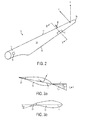
- FIG. 2 illustrates a blade 14 according to the invention.
- the blade 14 comprises a blade body 20 and a trailing edge flap 21 connected to the blade body for modifying the aerodynamic surface or shape of the rotor blade.
- the flap 21 is actuated so that it deflects, in order to alter the loads experienced by the wind turbine 1.
- Figure 3a is a cross section showing the blade profile along the line III-III in Figure 2 when the flap 21 is not deflected.
- Figure 3b is a cross section showing the blade profile along the line III-III in Figure 2 showing the flap 21 deflected. As can be seen the flap is deflected an angle ⁇ relative to the chord line c.
- trailing edge flaps 21 Although one trailing edge flaps 21 is shown, it should be appreciated that there may be more trailing edge flaps. For example, there may be three trailing edge flaps 21 per blade 14.
- the flaps are actuated by actuation means not shown; the actuation means may include electronic actuators, piezo-electric actuators or pneumatic actuators such as described in WO 2010/043647 .
- the wind turbine blades 14 experience flapwise loads substantially normal to the chord c of the blade.
- Figure 2 shows the flapwise loads by the arrow F. Although only a point load is shown, it should be appreciated that the flapwise loads F act along the span of the blade 14. In use the blade also experience edgewise loads, and the direction of the edgewise loads is shown by the arrow E.
- Sensors 30 are provided at the root of the blade to measure the loading on the blade.
- the sensor 30 is a strain gauge at the root of the blade that measures the blade root bending moment in the flapwise direction and the edgewise direction. Further strain gauges may be located along the longitudinal direction of the blade for example at 20%, 40%, 50%, 60%, 75% and 80% of the blade radius to measure the loading on the blade.
- a five-hole pitot tube 35 is associated with the flap 21 and is mounted at the leading edge 17 to measure the wind speed and the angle of attack at the spanwise location of the flap.
- the pitot tube 35 detects the local wind conditions at the blade 14 or just in front of the blade and this information is used to control the flap 21 in order to reduce the loading experienced by the blade.
- the flap 21 is configured in order to reduce the flapwise loading of the blade, and in particular the flapwise blade root bending moment.
- the wind conditions in front of the blade can be detected by other sensors, such as by LIDAR or actually by using the flap as a sensor as described in EP2222955 .
- a controller uses the measurements from the pitot tube 35 (or other wind condition sensor) to control the flap 21.
- Figure 3a shows the local wind and aerodynamic forces at a blade section.
- the resultant wind velocity V_r is a combination of the free wind velocity V_wind and the rotational speed ⁇ r of the blade 14 at that radial location.
- the resultant wind velocity V_r is at an angle to the chord c of the blade profile and this is the angle of attack ⁇ .
- the pitch angle ⁇ is the angle between the chord c and the rotor plane (where the rotor plane is the rotational plane of the rotor which is normal to the rotational axis of the rotor).
- the pitch angle ⁇ is set for the whole blade 14 by rotating the blade about its longitudinal axis.
- the lift force for the blade section is defined as L and the drag force for the blade section is defined as D.
- FIG 4 is a schematic of a first example of the controller 50 to control a flap 21.
- the controller 50 At the input to the controller 50 are the sensed wind conditions from the pitot tube 35 and at the output is a flap angle demand to be sent to an actuator 55 used to drive the flap to the desired angle.
- the wind speed and the angle of attack sensed by the pitot tube are 35 are passed to a lift calculation unit 51 which calculates the change in lift at the blade section (to be provided by moving the flap) that is needed to counteract wind disturbances to keep a constant lift force at the blade section - this change in lift value is defined as ⁇ L.
- the wind disturbances may be a result of turbulence, or local gusts. These vary as a function of time and therefore, ⁇ L also varies as a function of time.
- the output from the lift calculation unit 51, ⁇ L is passed to a high pass filter 52 in order to remove low frequency components from the ⁇ L signal.
- the purpose of the high pass filter 52 is to ensure that the flaps are used to counteract fluctuations caused by the turbulent wind conditions and the rotation of the blades, rather than the low frequency variations in the average wind speed.
- the high pass filter is arranged to remove frequency components below the rotation frequency of the rotor.
- the filtered ⁇ L signal is then sent to an amplifier 53 which applies a gain to the ⁇ L signal.
- the output of the amplifier 53 is the flap angle demand to be sent to the actuator 55 in order to move the flap.
- the amplifier 53 is linear, but it is also possible to apply a non-linear gain.
- the flap angle demand output from the amplifier is sent to the actuator 55, it is passed through a notch filter 54 in order to remove predetermined frequency components from the flap angle demand.
- the flap 21 is used to control the flapwise bending moments of the rotor blade 14.
- the inventors of the invention have realised that in a wind turbine blade there is coupling between the flapwise moments of the blade and the edgewise moments of the blade, and if the flap 21 is excited in order to reduce flapwise moments this may have an adverse effect on the edgewise moments of the blade. If the flap 21 is operated at a frequency that happens to coincide with an edgewise resonant frequency, the flap will stimulate the edgewise resonant mode and lead to high edgewise loads in the blades which could potentially cause damage to the blade.
- the notch filter 54 is configured to remove frequencies from the flap angle demand at the edgewise resonant frequency of the blade.
- the blade may have more than one edgewise resonant frequency, but in this example the notch filter 54 is configured to remove the lowest edgewise resonant frequency only as the first edgewise frequency is typically the most dominant edgewise frequency.
- the blade 14 is 45 meters long and the edgewise resonant frequency of the blade is 0.9 Hz.
- the notch filter 54 is arranged to attenuate frequencies at and around this edgewise resonant frequency, so in this example the notch filter 54 removes frequency components in the flap angle demand from 0.8 Hz to 1 Hz. By removing these frequency components from the flap angle demand signal, and hence preventing the flap 21 from operating at this frequency range, stimulation of the edgewise resonant frequency of the blade is avoided.
- flap angle demand is used herein to refer to the signal from the amplifier 53, that is the flap angle demand before it is passed through the notch filter 54.
- the output of the notch filter is referred to herein as the "operating flap angle demand” and it is this signal that is sent to the actuator 55 to move the flap.
- flap angle demand refers to the pre-notch filtered signal
- operating flap angle demand refers to the post-notch filtered signal.
- the operating flap angle demand is the angle at which the flap is moved to, namely ⁇ according to Figure 3b .
- the controller 50 will now be described further with reference to the graphs in Figures 5 to 9 .
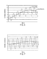
- Figure 6 shows the initial angle ( ⁇ _initial) and the operating angle ( ⁇ _operate) as a function of time.
- the dashed line 61 is the initial angle ( ⁇ _initial), measured in degrees and the solid line 62 is the operating angle ( ⁇ _operate).
- the operating angle ( ⁇ _operate) signal 62 has a different frequency content to the initial angle ( ⁇ _initial) signal 61.
- frequency components from the initial angle ( ⁇ _initial) 61 that may excite the edgewise resonant frequency of the blade 14 have been removed from the initial angle ( ⁇ _initial) 61 to result in the operating angle ( ⁇ _operate) 62.
- Figure 7 shows the edgewise loading on the blade 14 as a function of time.
- the dashed line 63 is the edgewise loading if the initial angle ( ⁇ _initial) is applied to the flap 21 without it being filtered by the notch filter 54.
- the initial angle ( ⁇ _initial) would excite the edgewise resonant frequency of the blade 14 resulting in high edgewise loading which could damage the blade or even cause the blade to fail.
- the solid line 64 shows the edgewise loading on the blade when the operating angle ( ⁇ _operate) is applied to the flap 21, that is the signal has been filtered by the notch filter 54.
- the edgewise loading that the blade experiences is much less that than the edgewise loading experienced by the blade when the notch filter 54 is not used.
- edgewise loading - As can be seen from solid line 64 there is still edgewise loading on the blade.
- this is the edgewise loading caused by the weight of the rotor blade itself as it generates alternating tensile and compression forces along its length as it rotates, and the edgewise loading which results from acceleration/deceleration of the rotor and changes in aerodynamic drag - i.e. this is the edgewise loading that the blade would have seen anyway (from whatever cause) without the additional loading that would have resulted from exciting the structural resonance by the flap.
- This has a frequency which is the so-called 1 P rotational frequency of the wind turbine rotor.
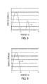
- Figures 8 and 9 show the edgewise loading on the blade in the frequency domain.
- the dashed line 65 in Figure 8 is the edgewise loading on the blade 14 if the flap 21 is operated according to the initial angle ( ⁇ _initial), that is without use of the notch filter 54.
- the first peak at around 0.25 Hz is the 1 P edgewise loading of the wind turbine blade 14.
- the second peak at around 0.9 Hz is where the flap 21 has excited the edgewise resonant frequency of the blade 14 and caused high edgewise loads.
- the solid line 66 represents the edgewise loading on the blade 14 when the flap is operated according to the operating angle ( ⁇ _operate) and the notch filter 54 is used.
- the edgewise loading peak at 0.9 Hz has been removed by the notch filter 54 as the edgewise resonant frequency of the blade 14 is not excited.
- the first peak at around 0.25 Hz still exists because this is the 1 P frequency caused by the cyclic rotation of the blades.
- the edgewise resonant frequency of the blade is 0.9 Hz and the flaps 21 are designed to counteract wind disturbances having a frequency range between 0.1 Hz and 1.5 Hz.
- the notch filter 54 prevents the flap from operating at a frequency of 0.8 Hz to 1 Hz.
- the notch filter 54 could be replaced with a low-pass filter than prevents the flap 21 from operating at frequencies higher than 0.8 Hz.
- the blade 14 is of a "soft” or “flexible” design, rather than a “stiff” blade, it will have a much lower edgewise resonant frequency, such as 0.1 Hz.
- the notch filter 54 could be replaced with a high-pass filter that prevents the flap from operating at frequencies below 0.2 Hz, in order to avoid stimulating the edgewise resonant frequency.
- the flap 21 is actuated to respond to changes in local wind disturbances at the rotor blade 14 in order to reduce fluctuations in the lift force experienced by the blade.
- the control of the flap is a feed-forward control system based on wind disturbances detected by the sensors 35.
- FIG 10 is a schematic of a second example of a controller 70 to control the flap 21, where the control of the flap is based on feed-forward measurements and feedback measurements.
- the feed-forward part of the controller 70 is the same as that described with respect to Figure 4 , and this is shown in the top half of Figure 10 and is referred to as the "feed-forward control branch".
- the feedback control system In the lower half of Figure 10 is shown the feedback control system and this is referred to as the "feedback control branch".
- changes in the blade root flapwise moment which are detected by strain gauge 30 are passed via box 71 to a high pass filter 72 in order to remove low frequency components from this signal.
- the purpose of the high pass filter 72 is to ensure that the flaps are used to counteract fluctuations caused by the turbulent wind conditions, rather than the low frequency variations in the average wind speed.
- the high pass filter is arranged to remove frequency components below 0.5 Hz, which in this example is two rotor revolutions.
- the filtered signal is then sent to an amplifier 73 which applies a gain to the change in blade root flapwise moment signal.
- the output of the amplifier 73 is a flap angle demand to be sent to the actuator 55 in order to move the flap.
- the amplifier 73 is a linear, but it is also possible to apply a non-linear gain.
- the flap angle demand from the amplifier 53 and the amplifier 73 are summed at an adder unit 74 to combine the feed-forward flap angle demand signal and the feedback flap angle demand signal.
- the summed flap angle demand signal is then input to the notch filter as described above with respect to Figure 4 .
- the amplifiers 53 and 73 may apply a linear gain to the input signal.
- the notch filter 54 does not necessarily need to be located immediately before the actuator as shown in Figures 4 and 10 .
- the notch filter may actually be located anywhere.
- a first notch filter may be located before the lift calculation unit 51 and in the feedback control branch of Figure 10 , a second notch filter may be located before the high pass filter 72 - the output from the adder unit is then input straight to the actuator 55 as the signals have already passed through notch filters.
- the amplifier 53 and the amplifier 73 may in another example, be proportional-integral-derivative controllers (PID controllers), proportional-integral controllers (PI controllers) or proportional-derivative controllers (PD controllers).
- PID controllers proportional-integral-derivative controllers
- PI controllers proportional-integral controllers
- PD controllers proportional-derivative controllers
- each flap 21 would have a pitot tube 35 (or other flow sensor) associated with it to measure the local wind conditions at the blade, including the local wind speed and the local angle of attack at the spanwise location of the flap 21.
- Each flap 21 may have its own controller 50, 70 or one controller may be provided for all the flaps. However, even if one controller is used for multiple flaps, each flap must have its own feed-forward control branch as this branch calculates changes in lift for each flap locally. But, a single feedback control branch can be used for all flaps.
- trailing edge flaps Although the invention has been described with respect to trailing edge flaps, it is applicable to other movable aerodynamic devices on a wind turbine blade which are moved in order to reduce the loading on a blade. These may include leading edge flaps, microtabs, spoilers or active vortex generators. In the case of spoilers, microtabs and active vortex generators, these devices may not actually be set at an angle but are rather “deflected” or “not deflected” in the oncoming wind flow. However, the principles of the invention still apply that these devices are prevented from operating at a frequency that will excite the edgewise resonant frequency of the blade.
Landscapes
- Engineering & Computer Science (AREA)
- Life Sciences & Earth Sciences (AREA)
- Sustainable Development (AREA)
- Sustainable Energy (AREA)
- Chemical & Material Sciences (AREA)
- Combustion & Propulsion (AREA)
- Mechanical Engineering (AREA)
- General Engineering & Computer Science (AREA)
- Physics & Mathematics (AREA)
- Fluid Mechanics (AREA)
- Wind Motors (AREA)
Abstract
Description
- Most modern wind turbines are controlled and regulated continuously during operation with the purpose of ensuring optimal performance of the wind turbines in all operating conditions, such as at different wind speeds or subject to different demands from the power grid.
- A well-known and effective method of regulating the loads on the rotor is by pitching the blades about the longitudinal axis of each blade. However, as the blades increase in size on modern wind turbines (which at present can be 60 m or longer) pitching becomes a relatively slow regulation method incapable of changing the blade positions fast enough to account for wind gusts, turbulence or other relatively fast load variations.
- Another way of regulating the loads on the blades is by changing their aerodynamic surfaces or shapes over parts or the entire length of the blade, thereby increasing or decreasing the blade lift or drag correspondingly. Different means of changing the airfoil shape are known such as different types of movable aerodynamic device, for example trailing edge flaps, leading edge slats, spoilers or active vortex generators.
- These movable aerodynamic devices are operated to reduce loading on the wind turbine blade by counteracting wind disturbances in the oncoming wind flow. The movable aerodynamic devices change the shape of the rotor blade airfoil section so that the lift and/or drag forces generated by the blade are smoothed out, with the result that the loading on the rotor blade is reduced. Reducing the loading experienced by the rotor blade also reduces the flapwise movement of the rotor blade. This reduces the fatigue loading of the rotor blade.
- However, when designing a wind turbine blade with a movable aerodynamic device, such as a trailing edge flap, it is necessary to ensure that the use of such a device does not result in the blade being subjected to loading that exceeds its design loads. It is the aim of the present invention to provide a method and a controller for a movable aerodynamic device that prevents the rotor blade being subjected to unacceptable load levels caused by the movable aerodynamic device.
- According to a first aspect of the present invention, there is provided a method of controlling a movable aerodynamic device on a wind turbine rotor blade, the method comprising the steps of:
- determining a device position demand as a function of time, the device position demand being calculated to reduce loading in the blade;
- moving the device according to the device position demand; and
- preventing the device from operating in a predetermined frequency band.
- The movable aerodynamic device, which may for example be a trailing edge flap, is configured to move in order to alter the aerodynamic profile of the blade. Altering the aerodynamic profile of the blade will change the aerodynamic forces generated by the rotor blade in order to reduce loading on the wind turbine blade.
- During operation, the rotor blades of a wind turbine rotate through a substantially vertical plane. The weight of the rotor blade itself generates alternating tensile and compression forces along its length as it rotates, which results in cyclic loading of each rotor blade. In particular, the alternating tensile and compression forces are experienced along the leading edge of a blade and along the trailing edge of a blade. These loads are commonly referred to in the art as "edgewise loads", or they are sometimes known as "chordwise loads". The edgewise loads result partly from gravitational loading and this edgewise loading increases from the tip of the blade to the root of the blade; edgewise loading also results from acceleration/deceleration of the rotor (inertial loading), structural coupling between flapwise and edgewise movement, and changes in aerodynamic drag which can be caused by flaps being operated. The rotor blades during operation are also subjected to flapwise loads due to wind disturbances such as turbulence and gusts. "Flapwise" is typically used in the art to refer to the direction substantially normal to the chord of the blade, where the "chord" is the distance between the leading edge and the trailing edge, i.e. the flapwise direction is the direction in which the aerodynamic lift acts. The flapwise direction is perpendicular to the edgewise direction.
- The present invention prevents the movable aerodynamic device from operating in a predetermined frequency band in order to prevent the rotor blade being subjected to unacceptably high levels of loading.
- By "predetermined frequency band" is meant some frequency band that is determined when the wind turbine is designed.
- Preferably, the step of preventing the movable aerodynamic device from operating in a predetermined frequency band may comprise: removing frequency components from the device position demand at the edgewise resonant frequency of the rotor blade.
- The movable aerodynamic device is used to control fatigue loading on the blade, and in particular to reduce the flapwise loading and movement of the blade. When controlling the flapwise loading on the blade there is a risk that the edgewise loading on the blade will be increased if the edgewise resonant frequency of the blade is stimulated - this is because there may be structural coupling effects between the flapwise movement of the blade which the movable aerodynamic device is controlling and edgewise movement of the blade. The present invention prevents the edgewise loading from being increased when the movable aerodynamic device is operated by preventing the device from moving at the edgewise resonant frequency of the rotor blade.
- Preferably, the width of the frequency band is 0.2 Hz. The width of the frequency band must be narrow enough so that it does not have a deleterious effect on the control of the flapwise loading, but wide enough so that it includes the range of edgewise resonant frequencies that occur during operating conditions and as a result of manufacturing tolerances during manufacture of the blade.
- Preferably, the device position demand is calculated to reduce flapwise loading in the blade.
- Preferably, the device position demand comprises:
- a feed-forward device position demand component as a function of time; and/or
- a feedback device position demand component as a function of time.
- Preferably, the feed-forward device position demand component is a device position determined to counteract wind disturbances at the rotor blade or upstream of the rotor blade.
- These wind disturbances may be local wind gusts or turbulence. The wind disturbances may be sensed at the rotor blade with a pitot tube for example, or at a distance in front of the blade up to 100 meters by a LIDAR unit.
- Preferably, the step of determining the feed-forward device position demand component comprises:
- detecting wind conditions at the rotor blade or upstream of the rotor blade with a sensor; and
- determining the feed-forward device position demand component so that movement of the device according to the feed-forward device position demand component counteracts wind disturbances in the detected wind conditions, such that loading in the blade is reduced.
- Preferably, the feedback device position demand component is a device position determined to minimise changes in loading of the blade.
- Preferably, the step of determining the feedback device position demand component comprises:
- detecting changes in loading of the blade with a sensor;
- determining the feedback device position demand component so that movement of the device according to the feedback device position demand component minimises the changes in loading of the blade.
- Preferably, the step of determining the device position demand comprises:
- summing the feed-forward device position demand component with the feedback device position demand component.
- Preferably, the step of preventing the device from operating in a predetermined frequency band comprises:
- applying a filter to the device position demand.
- The step of preventing the device from operating in a predetermined frequency band may comprise:
- applying a filter to the feed-forward device position demand component; and/or
- applying a filter to the feedback device position demand component.
- The step of preventing the device from operating in a predetermined frequency band may comprise: applying a filter to the detected wind conditions.
- The step of preventing the device from operating in a predetermined frequency band may comprise: applying a filter to the detected changes in loading of the blade.
- The filter may comprise a band-stop filter.
- The filter may comprise a notch filter.
- The filter may comprise a high-pass filter or a low-pass filter.
- The movable aerodynamic device may be one of a trailing edge flap, a leading edge flap, a movable spoiler, a microtab, a movable vortex generator.
- Preferably, the movable aerodynamic device is a trailing edge flap and the device position demand is a flap angle demand.
- According to a second aspect of the present invention there is provided a controller for a wind turbine rotor blade, the wind turbine rotor blade having a movable aerodynamic device, the controller being arranged to carry out the method as described above according to the first aspect of the present invention.
- According to a third aspect of the present invention there is provided a wind turbine having a rotor blade having a movable aerodynamic device, the wind turbine comprising a controller according to the second aspect of the present invention.
- Preferably, the wind turbine is a three blades upwind horizontal axis turbine.
- The present invention will now be described in more detail, by way of example only, with reference to the accompanying drawings in which:
-
Figure 1 is a view of a horizontal axis wind turbine; -
Figure 2 is a view of a wind turbine blade; -
Figures 3a and 3b are cross sectional views of a wind turbine blade; -
Figure 4 is a schematic of a first example of a controller according to the invention; -
Figure 5 shows a change in lift value as a function of time; -
Figure 6 shows a flap angle position as a function of time; -
Figure 7 shows edgewise loading as a function of time; -
Figure 8 and 9 show edgewise loading in the frequency domain; -
Figure 10 is a schematic of a second example of a controller according to the invention. -
Figure 1 shows a horizontalaxis wind turbine 10 according to the invention. The turbine comprises atower 11 which supports anacelle 12. Thewind turbine 10 comprises arotor 13 made up of threeblades 14 each having aroot end 15 mounted on ahub 16. Eachblade 14 comprises aleading edge 17, a trailingedge 18, and atip 19. - As is well known in the art, each
blade 14 can pitch about its own pitch axis which extends longitudinally along the span of the blade. Theblades 14 are typically set at a fixed pitch angle until a rated wind speed is reached. At wind speeds above the rated wind speed, theblades 14 are pitched out of the wind in order to regulate the power output of the wind turbine so that the rated power output of the wind turbine is not exceeded. The turbine's controller monitors the electrical power output of the turbine and if the power output is too high, the blades are pitched out of the wind. Conversely, the blades are pitched back into the wind whenever the wind drops again and the electrical power output drops. -
Figure 2 illustrates ablade 14 according to the invention. Theblade 14 comprises ablade body 20 and a trailingedge flap 21 connected to the blade body for modifying the aerodynamic surface or shape of the rotor blade. In use, when the turbine is generating power, theflap 21 is actuated so that it deflects, in order to alter the loads experienced by thewind turbine 1. -
Figure 3a is a cross section showing the blade profile along the line III-III inFigure 2 when theflap 21 is not deflected.Figure 3b is a cross section showing the blade profile along the line III-III inFigure 2 showing theflap 21 deflected. As can be seen the flap is deflected an angle β relative to the chord line c. - Although one trailing edge flaps 21 is shown, it should be appreciated that there may be more trailing edge flaps. For example, there may be three trailing edge flaps 21 per
blade 14. The flaps are actuated by actuation means not shown; the actuation means may include electronic actuators, piezo-electric actuators or pneumatic actuators such as described inWO 2010/043647 . - In use, the
wind turbine blades 14 experience flapwise loads substantially normal to the chord c of the blade.Figure 2 shows the flapwise loads by the arrow F. Although only a point load is shown, it should be appreciated that the flapwise loads F act along the span of theblade 14. In use the blade also experience edgewise loads, and the direction of the edgewise loads is shown by the arrow E. -
Sensors 30 are provided at the root of the blade to measure the loading on the blade. In this example, thesensor 30 is a strain gauge at the root of the blade that measures the blade root bending moment in the flapwise direction and the edgewise direction. Further strain gauges may be located along the longitudinal direction of the blade for example at 20%, 40%, 50%, 60%, 75% and 80% of the blade radius to measure the loading on the blade. - A five-
hole pitot tube 35 is associated with theflap 21 and is mounted at theleading edge 17 to measure the wind speed and the angle of attack at the spanwise location of the flap. Thepitot tube 35 detects the local wind conditions at theblade 14 or just in front of the blade and this information is used to control theflap 21 in order to reduce the loading experienced by the blade. In this example, theflap 21 is configured in order to reduce the flapwise loading of the blade, and in particular the flapwise blade root bending moment. The wind conditions in front of the blade can be detected by other sensors, such as by LIDAR or actually by using the flap as a sensor as described inEP2222955 . A controller (not shown inFigure 2 ) uses the measurements from the pitot tube 35 (or other wind condition sensor) to control theflap 21. -
Figure 3a shows the local wind and aerodynamic forces at a blade section. As can be seen, the resultant wind velocity V_r is a combination of the free wind velocity V_wind and the rotational speed ωr of theblade 14 at that radial location. The resultant wind velocity V_r is at an angle to the chord c of the blade profile and this is the angle of attack α. The pitch angle θ is the angle between the chord c and the rotor plane (where the rotor plane is the rotational plane of the rotor which is normal to the rotational axis of the rotor). The pitch angle θ is set for thewhole blade 14 by rotating the blade about its longitudinal axis. The lift force for the blade section is defined as L and the drag force for the blade section is defined as D. - Moving the flap to different angles (as shown in
Figure 3b ) changes the lift and drag force at the blade section to alter the aerodynamic performance of the blade. Therefore, the aerodynamic loads experienced by the blade can be regulated by moving theflap 21 in order to smooth out fluctuations in the lift force, where the fluctuations may be caused by local wind conditions. -
Figure 4 is a schematic of a first example of thecontroller 50 to control aflap 21. At the input to thecontroller 50 are the sensed wind conditions from thepitot tube 35 and at the output is a flap angle demand to be sent to anactuator 55 used to drive the flap to the desired angle. In the controller, the wind speed and the angle of attack sensed by the pitot tube are 35 are passed to alift calculation unit 51 which calculates the change in lift at the blade section (to be provided by moving the flap) that is needed to counteract wind disturbances to keep a constant lift force at the blade section - this change in lift value is defined as ΔL. - The wind disturbances may be a result of turbulence, or local gusts. These vary as a function of time and therefore, ΔL also varies as a function of time.
- The output from the
lift calculation unit 51, ΔL, is passed to ahigh pass filter 52 in order to remove low frequency components from the ΔL signal. The purpose of thehigh pass filter 52 is to ensure that the flaps are used to counteract fluctuations caused by the turbulent wind conditions and the rotation of the blades, rather than the low frequency variations in the average wind speed. In this example, the high pass filter is arranged to remove frequency components below the rotation frequency of the rotor. - The filtered ΔL signal is then sent to an
amplifier 53 which applies a gain to the ΔL signal. The output of theamplifier 53 is the flap angle demand to be sent to theactuator 55 in order to move the flap. In this example, theamplifier 53 is linear, but it is also possible to apply a non-linear gain. However, before the flap angle demand output from the amplifier is sent to theactuator 55, it is passed through anotch filter 54 in order to remove predetermined frequency components from the flap angle demand. - The
flap 21 is used to control the flapwise bending moments of therotor blade 14. However, the inventors of the invention have realised that in a wind turbine blade there is coupling between the flapwise moments of the blade and the edgewise moments of the blade, and if theflap 21 is excited in order to reduce flapwise moments this may have an adverse effect on the edgewise moments of the blade. If theflap 21 is operated at a frequency that happens to coincide with an edgewise resonant frequency, the flap will stimulate the edgewise resonant mode and lead to high edgewise loads in the blades which could potentially cause damage to the blade. - The
notch filter 54 is configured to remove frequencies from the flap angle demand at the edgewise resonant frequency of the blade. The blade may have more than one edgewise resonant frequency, but in this example thenotch filter 54 is configured to remove the lowest edgewise resonant frequency only as the first edgewise frequency is typically the most dominant edgewise frequency. - In this example, the
blade 14 is 45 meters long and the edgewise resonant frequency of the blade is 0.9 Hz. Thenotch filter 54 is arranged to attenuate frequencies at and around this edgewise resonant frequency, so in this example thenotch filter 54 removes frequency components in the flap angle demand from 0.8 Hz to 1 Hz. By removing these frequency components from the flap angle demand signal, and hence preventing theflap 21 from operating at this frequency range, stimulation of the edgewise resonant frequency of the blade is avoided. - The term "flap angle demand" is used herein to refer to the signal from the
amplifier 53, that is the flap angle demand before it is passed through thenotch filter 54. The output of the notch filter is referred to herein as the "operating flap angle demand" and it is this signal that is sent to theactuator 55 to move the flap. In other words, "flap angle demand" refers to the pre-notch filtered signal and "operating flap angle demand" refers to the post-notch filtered signal. The operating flap angle demand is the angle at which the flap is moved to, namely β according toFigure 3b . - To avoid confusion, the term "flap angle demand" will now be referred to as "initial angle, β_initial" and the term "operating flap angle demand, β_operate" will now be referred to as "operating angle, β_operate".
- The
controller 50 will now be described further with reference to the graphs inFigures 5 to 9 . - In
Figure 5 , the change in lift value ΔL is shown as a function of time, where ΔL is calculated by thelift calculation unit 51. This change in lift value ΔL is related to the wind disturbances, and as the wind is stochastic the ΔL value will represent these stochastic disturbances as ΔL is determined in order to counteract the wind disturbances. -
Figure 6 shows the initial angle (β_initial) and the operating angle (β_operate) as a function of time. The dashedline 61 is the initial angle (β_initial), measured in degrees and thesolid line 62 is the operating angle (β_operate). As can clearly be seen, the operating angle (β_operate) signal 62 has a different frequency content to the initial angle (β_initial)signal 61. In particular, frequency components from the initial angle (β_initial) 61 that may excite the edgewise resonant frequency of theblade 14 have been removed from the initial angle (β_initial) 61 to result in the operating angle (β_operate) 62. -
Figure 7 shows the edgewise loading on theblade 14 as a function of time. The dashedline 63 is the edgewise loading if the initial angle (β_initial) is applied to theflap 21 without it being filtered by thenotch filter 54. In this example, the initial angle (β_initial) would excite the edgewise resonant frequency of theblade 14 resulting in high edgewise loading which could damage the blade or even cause the blade to fail. - In contrast, in
Figure 7 , thesolid line 64 shows the edgewise loading on the blade when the operating angle (β_operate) is applied to theflap 21, that is the signal has been filtered by thenotch filter 54. As can be seen, the edgewise loading that the blade experiences is much less that than the edgewise loading experienced by the blade when thenotch filter 54 is not used. - Using the
notch filter 54 will not eliminate the edgewise loading - as can be seen fromsolid line 64 there is still edgewise loading on the blade. However, this is the edgewise loading caused by the weight of the rotor blade itself as it generates alternating tensile and compression forces along its length as it rotates, and the edgewise loading which results from acceleration/deceleration of the rotor and changes in aerodynamic drag - i.e. this is the edgewise loading that the blade would have seen anyway (from whatever cause) without the additional loading that would have resulted from exciting the structural resonance by the flap. This has a frequency which is the so-called 1 P rotational frequency of the wind turbine rotor. -
Figures 8 and 9 show the edgewise loading on the blade in the frequency domain. In particular, the dashedline 65 inFigure 8 is the edgewise loading on theblade 14 if theflap 21 is operated according to the initial angle (β_initial), that is without use of thenotch filter 54. The first peak at around 0.25 Hz is the 1 P edgewise loading of thewind turbine blade 14. The second peak at around 0.9 Hz is where theflap 21 has excited the edgewise resonant frequency of theblade 14 and caused high edgewise loads. - In
Figure 9 , the solid line 66 represents the edgewise loading on theblade 14 when the flap is operated according to the operating angle (β_operate) and thenotch filter 54 is used. As can clearly be seen, the edgewise loading peak at 0.9 Hz has been removed by thenotch filter 54 as the edgewise resonant frequency of theblade 14 is not excited. The first peak at around 0.25 Hz still exists because this is the 1 P frequency caused by the cyclic rotation of the blades. - In this example, the edgewise resonant frequency of the blade is 0.9 Hz and the
flaps 21 are designed to counteract wind disturbances having a frequency range between 0.1 Hz and 1.5 Hz. Thenotch filter 54 prevents the flap from operating at a frequency of 0.8 Hz to 1 Hz. However, if in the design process of the flaps it has been decided to only counteract wind disturbances having a frequency range of between 0.1 Hz to 1 Hz, then thenotch filter 54 could be replaced with a low-pass filter than prevents theflap 21 from operating at frequencies higher than 0.8 Hz. - Similarly, if the
blade 14 is of a "soft" or "flexible" design, rather than a "stiff" blade, it will have a much lower edgewise resonant frequency, such as 0.1 Hz. In this example thenotch filter 54 could be replaced with a high-pass filter that prevents the flap from operating at frequencies below 0.2 Hz, in order to avoid stimulating the edgewise resonant frequency. - In the first example of
Figure 4 , theflap 21 is actuated to respond to changes in local wind disturbances at therotor blade 14 in order to reduce fluctuations in the lift force experienced by the blade. In this first example, the control of the flap is a feed-forward control system based on wind disturbances detected by thesensors 35. -
Figure 10 is a schematic of a second example of acontroller 70 to control theflap 21, where the control of the flap is based on feed-forward measurements and feedback measurements. The feed-forward part of thecontroller 70 is the same as that described with respect toFigure 4 , and this is shown in the top half ofFigure 10 and is referred to as the "feed-forward control branch". In the lower half ofFigure 10 is shown the feedback control system and this is referred to as the "feedback control branch". - In the feedback control branch, changes in the blade root flapwise moment which are detected by
strain gauge 30 are passed viabox 71 to ahigh pass filter 72 in order to remove low frequency components from this signal. The purpose of thehigh pass filter 72 is to ensure that the flaps are used to counteract fluctuations caused by the turbulent wind conditions, rather than the low frequency variations in the average wind speed. In this example, the high pass filter is arranged to remove frequency components below 0.5 Hz, which in this example is two rotor revolutions. - The filtered signal is then sent to an
amplifier 73 which applies a gain to the change in blade root flapwise moment signal. The output of theamplifier 73 is a flap angle demand to be sent to theactuator 55 in order to move the flap. In this example, theamplifier 73 is a linear, but it is also possible to apply a non-linear gain. - The flap angle demand from the
amplifier 53 and theamplifier 73 are summed at anadder unit 74 to combine the feed-forward flap angle demand signal and the feedback flap angle demand signal. The summed flap angle demand signal is then input to the notch filter as described above with respect toFigure 4 . - The
amplifiers notch filter 54 does not necessarily need to be located immediately before the actuator as shown inFigures 4 and10 . With a linear control system, the notch filter may actually be located anywhere. For example, in the feed-forward control branch ofFigure 10 , a first notch filter may be located before thelift calculation unit 51 and in the feedback control branch ofFigure 10 , a second notch filter may be located before the high pass filter 72 - the output from the adder unit is then input straight to theactuator 55 as the signals have already passed through notch filters. - The
amplifier 53 and theamplifier 73 may in another example, be proportional-integral-derivative controllers (PID controllers), proportional-integral controllers (PI controllers) or proportional-derivative controllers (PD controllers). - As described above, more trailing edge flaps 21 may be present on the
wind turbine blade 14. In this case, eachflap 21 would have a pitot tube 35 (or other flow sensor) associated with it to measure the local wind conditions at the blade, including the local wind speed and the local angle of attack at the spanwise location of theflap 21. Eachflap 21 may have itsown controller - Although the invention has been described with respect to trailing edge flaps, it is applicable to other movable aerodynamic devices on a wind turbine blade which are moved in order to reduce the loading on a blade. These may include leading edge flaps, microtabs, spoilers or active vortex generators. In the case of spoilers, microtabs and active vortex generators, these devices may not actually be set at an angle but are rather "deflected" or "not deflected" in the oncoming wind flow. However, the principles of the invention still apply that these devices are prevented from operating at a frequency that will excite the edgewise resonant frequency of the blade.
Claims (21)
- A method of controlling a movable aerodynamic device on a wind turbine rotor blade, the method comprising the steps of:determining a device position demand as a function of time, the device position demand being calculated to reduce loading in the blade;moving the device according to the device position demand; andpreventing the device from operating in a predetermined frequency band.
- A method according to claim 1, wherein the step of preventing the movable aerodynamic device from operating in a predetermined frequency band comprises:removing frequency components from the device position demand at the edgewise resonant frequency of the rotor blade.
- A method according to claim 1 or claim 2, wherein the width of the frequency band is 0.2 Hz.
- A method according to any one of the preceding claims, wherein the device position demand is calculated to reduce flapwise loading in the blade.
- A method according to any one of the preceding claims, wherein the device position demand comprises:a feed-forward device position demand component as a function of time; and/ora feedback device position demand component as a function of time.
- A method according to claim 5, wherein the feed-forward device position demand component is a device position determined to counteract wind disturbances detected at the rotor blade or detected upstream of the rotor blade.
- A method according to claim 6, wherein the step of determining the feed-forward device position demand component comprises:detecting wind conditions at the rotor blade or upstream of the rotor blade with a sensor; anddetermining the feed-forward device position demand component so that movement of the device according to the feed-forward device position demand component counteracts wind disturbances in the detected wind conditions, such that loading in the blade is reduced.
- A method according to any one of claims 5 to 7, wherein the feedback device position demand component is a device position determined to minimise changes in loading of the blade.
- A method according to claim 8, wherein the step of determining the feedback device position demand component comprises:detecting changes in loading of the blade with a sensor;determining the feedback device position demand component so that movement of the device according to the feedback device position demand component minimises the changes in loading of the blade.
- A method according to any claims 5 to 9, wherein the step of determining the device position demand comprises:summing the feed-forward device position demand component with the feedback device position demand component.
- A method according to any one of the preceding claims, wherein the step of preventing the device from operating in a predetermined frequency band comprises:applying a filter to the device position demand.
- A method according to any of claims 5 to 10, wherein the step of preventing the device from operating in a predetermined frequency band comprises:applying a filter to the feed-forward device position demand component; and/orapplying a filter to the feedback device position demand component.
- A method according to claim 7, wherein the step of preventing the device from operating in a predetermined frequency band comprises:applying a filter to the detected wind conditions.
- A method according to claim 9, wherein the step of preventing the device from operating in a predetermined frequency band comprises:applying a filter to the detected changes in loading of the blade.
- A method according to any of claims 11 to 14, wherein the filter comprises a band-stop filter.
- A method according to any of claims 11 to 15, wherein the filter comprises a notch filter.
- A method according to any of claims 11 to 14, wherein the filter comprises a high-pass filter or a low-pass filter.
- A method according to any of the preceding claims, wherein the movable aerodynamic device is one of a trailing edge flap, a leading edge flap, a movable spoiler, a microtab, a movable vortex generator.
- A method according to any of claims 1 to 17, wherein the movable aerodynamic device is a trailing edge flap and the device position demand is a flap angle demand.
- A controller for a wind turbine rotor blade, the wind turbine rotor blade having a movable aerodynamic device, the controller being arranged to carry out the method according to any one of claims 1 to 17.
- A wind turbine having a rotor blade having a movable aerodynamic device, the wind turbine comprising a controller according to claim 20.
Applications Claiming Priority (2)
| Application Number | Priority Date | Filing Date | Title |
|---|---|---|---|
| US201261597197P | 2012-02-10 | 2012-02-10 | |
| DKPA201270069 | 2012-02-13 |
Publications (3)
| Publication Number | Publication Date |
|---|---|
| EP2626551A2 true EP2626551A2 (en) | 2013-08-14 |
| EP2626551A3 EP2626551A3 (en) | 2016-09-07 |
| EP2626551B1 EP2626551B1 (en) | 2019-06-12 |
Family
ID=47632933
Family Applications (1)
| Application Number | Title | Priority Date | Filing Date |
|---|---|---|---|
| EP13154383.7A Active EP2626551B1 (en) | 2012-02-10 | 2013-02-07 | A method of controlling a wind turbine |
Country Status (1)
| Country | Link |
|---|---|
| EP (1) | EP2626551B1 (en) |
Cited By (8)
| Publication number | Priority date | Publication date | Assignee | Title |
|---|---|---|---|---|
| CN107762730A (en) * | 2017-08-23 | 2018-03-06 | 华北电力大学 | A kind of large-scale change oar turbine control system and control method with trailing edge flaps |
| US9926912B2 (en) | 2016-08-30 | 2018-03-27 | General Electric Company | System and method for estimating wind coherence and controlling wind turbine based on same |
| WO2018233787A1 (en) * | 2017-06-20 | 2018-12-27 | Vestas Wind Systems A/S | METHOD FOR DETERMINING LOAD RECURRENCE WITHIN THE DIRECTION OF WHEELED BLADE TRAIN |
| US10294923B2 (en) | 2015-03-20 | 2019-05-21 | Vestas Wind Systems A/S | Damping oscillations in a wind turbine |
| US10539116B2 (en) | 2016-07-13 | 2020-01-21 | General Electric Company | Systems and methods to correct induction for LIDAR-assisted wind turbine control |
| CN111512043A (en) * | 2017-11-06 | 2020-08-07 | 维斯塔斯风力系统集团公司 | Method and system for controlling wind turbines to manage edge blade vibration |
| EP3892851A1 (en) * | 2020-04-09 | 2021-10-13 | General Electric Renovables España S.L. | System and method for improved extreme load control for wind turbine rotor blades |
| EP4414552A1 (en) * | 2023-02-09 | 2024-08-14 | Wobben Properties GmbH | Method for preventing mechanical vibrations of a wind turbine |
Families Citing this family (1)
| Publication number | Priority date | Publication date | Assignee | Title |
|---|---|---|---|---|
| DE102018007749A1 (en) * | 2018-10-02 | 2020-04-02 | Senvion Gmbh | Method and system for operating a wind turbine |
Family Cites Families (5)
| Publication number | Priority date | Publication date | Assignee | Title |
|---|---|---|---|---|
| ES2326203B1 (en) * | 2007-07-23 | 2010-07-09 | GAMESA INNOVATION & TECHNOLOGY, S.L. | AEROGENERATOR SHOVEL WITH ARCHABLE ALERONS. |
| US8192161B2 (en) * | 2008-05-16 | 2012-06-05 | Frontier Wind, Llc. | Wind turbine with deployable air deflectors |
| GB2469854A (en) * | 2009-04-30 | 2010-11-03 | Vestas Wind Sys As | Wind turbine rotor blade |
| GB2475694A (en) * | 2009-11-25 | 2011-06-01 | Vestas Wind Sys As | Flap control for wind turbine blades |
| DK177434B1 (en) * | 2010-06-18 | 2013-05-21 | Vestas Wind Sys As | Method for controlling a wind turbine |
-
2013
- 2013-02-07 EP EP13154383.7A patent/EP2626551B1/en active Active
Cited By (11)
| Publication number | Priority date | Publication date | Assignee | Title |
|---|---|---|---|---|
| US10294923B2 (en) | 2015-03-20 | 2019-05-21 | Vestas Wind Systems A/S | Damping oscillations in a wind turbine |
| US10539116B2 (en) | 2016-07-13 | 2020-01-21 | General Electric Company | Systems and methods to correct induction for LIDAR-assisted wind turbine control |
| US9926912B2 (en) | 2016-08-30 | 2018-03-27 | General Electric Company | System and method for estimating wind coherence and controlling wind turbine based on same |
| WO2018233787A1 (en) * | 2017-06-20 | 2018-12-27 | Vestas Wind Systems A/S | METHOD FOR DETERMINING LOAD RECURRENCE WITHIN THE DIRECTION OF WHEELED BLADE TRAIN |
| CN107762730A (en) * | 2017-08-23 | 2018-03-06 | 华北电力大学 | A kind of large-scale change oar turbine control system and control method with trailing edge flaps |
| CN107762730B (en) * | 2017-08-23 | 2019-06-18 | 华北电力大学 | Control system and control method of large-scale pitch wind turbine with trailing edge flaps |
| CN111512043A (en) * | 2017-11-06 | 2020-08-07 | 维斯塔斯风力系统集团公司 | Method and system for controlling wind turbines to manage edge blade vibration |
| EP3892851A1 (en) * | 2020-04-09 | 2021-10-13 | General Electric Renovables España S.L. | System and method for improved extreme load control for wind turbine rotor blades |
| CN113530757A (en) * | 2020-04-09 | 2021-10-22 | 通用电气可再生能源西班牙有限公司 | System and method for improved extreme load control for wind turbine rotor blades |
| US12392323B2 (en) | 2020-04-09 | 2025-08-19 | GE Vernova Renovables Espana, S.L. | System and method for improved extreme load control for wind turbine rotor blades |
| EP4414552A1 (en) * | 2023-02-09 | 2024-08-14 | Wobben Properties GmbH | Method for preventing mechanical vibrations of a wind turbine |
Also Published As
| Publication number | Publication date |
|---|---|
| EP2626551B1 (en) | 2019-06-12 |
| EP2626551A3 (en) | 2016-09-07 |
Similar Documents
| Publication | Publication Date | Title |
|---|---|---|
| EP2626551B1 (en) | A method of controlling a wind turbine | |
| CN103026059B (en) | The controlling method of wind turbine | |
| CN108026895B (en) | Wind turbine and method of operating a wind turbine having a rotational speed exclusion zone | |
| EP2633189B1 (en) | A method of controlling a wind turbine | |
| CN102619685B (en) | The wind turbine controlling method improved and system | |
| CN102648345B (en) | Control method for a wind turbine | |
| EP2859225B1 (en) | A method of operating a wind turbine as well as a system suitable therefore | |
| EP1442216B2 (en) | Rotor with extendable blades and control criteria therefor | |
| EP3469213B1 (en) | Damping of edgewise wind turbine blade vibrations | |
| US8128362B2 (en) | Method of operating a wind turbine, a wind turbine and a cluster of wind turbines | |
| EP2425129B1 (en) | Wind turbine rotor blade | |
| EP4426928A1 (en) | A method for reducing blade vibrations in a wind turbine | |
| CN102606394A (en) | Methods and systems for determining a pitch angle offset signal and for controlling a rotor frequency of a rotor of a wind turbine for speed avoidance control | |
| EP4426933A1 (en) | A method for reducing blade flap loads in a wind turbine | |
| US20230400010A1 (en) | Controlling an offshore wind turbine using active add-ons | |
| EP2927483A1 (en) | Noise control in wind turbines | |
| EP3020959B1 (en) | Methods of operating a wind turbine and wind turbines | |
| EP3580453B1 (en) | Method and system for controlling a wind turbine | |
| WO2018145715A1 (en) | Method and system for controlling a wind turbine |
Legal Events
| Date | Code | Title | Description |
|---|---|---|---|
| PUAI | Public reference made under article 153(3) epc to a published international application that has entered the european phase |
Free format text: ORIGINAL CODE: 0009012 |
|
| AK | Designated contracting states |
Kind code of ref document: A2 Designated state(s): AL AT BE BG CH CY CZ DE DK EE ES FI FR GB GR HR HU IE IS IT LI LT LU LV MC MK MT NL NO PL PT RO RS SE SI SK SM TR |
|
| AX | Request for extension of the european patent |
Extension state: BA ME |
|
| RAP1 | Party data changed (applicant data changed or rights of an application transferred) |
Owner name: VESTAS WIND SYSTEMS A/S |
|
| PUAL | Search report despatched |
Free format text: ORIGINAL CODE: 0009013 |
|
| AK | Designated contracting states |
Kind code of ref document: A3 Designated state(s): AL AT BE BG CH CY CZ DE DK EE ES FI FR GB GR HR HU IE IS IT LI LT LU LV MC MK MT NL NO PL PT RO RS SE SI SK SM TR |
|
| AX | Request for extension of the european patent |
Extension state: BA ME |
|
| RIC1 | Information provided on ipc code assigned before grant |
Ipc: F03D 7/04 20060101ALI20160801BHEP Ipc: F03D 7/02 20060101AFI20160801BHEP |
|
| STAA | Information on the status of an ep patent application or granted ep patent |
Free format text: STATUS: REQUEST FOR EXAMINATION WAS MADE |
|
| 17P | Request for examination filed |
Effective date: 20170302 |
|
| RBV | Designated contracting states (corrected) |
Designated state(s): AL AT BE BG CH CY CZ DE DK EE ES FI FR GB GR HR HU IE IS IT LI LT LU LV MC MK MT NL NO PL PT RO RS SE SI SK SM TR |
|
| GRAP | Despatch of communication of intention to grant a patent |
Free format text: ORIGINAL CODE: EPIDOSNIGR1 |
|
| STAA | Information on the status of an ep patent application or granted ep patent |
Free format text: STATUS: GRANT OF PATENT IS INTENDED |
|
| INTG | Intention to grant announced |
Effective date: 20190103 |
|
| GRAS | Grant fee paid |
Free format text: ORIGINAL CODE: EPIDOSNIGR3 |
|
| GRAA | (expected) grant |
Free format text: ORIGINAL CODE: 0009210 |
|
| STAA | Information on the status of an ep patent application or granted ep patent |
Free format text: STATUS: THE PATENT HAS BEEN GRANTED |
|
| AK | Designated contracting states |
Kind code of ref document: B1 Designated state(s): AL AT BE BG CH CY CZ DE DK EE ES FI FR GB GR HR HU IE IS IT LI LT LU LV MC MK MT NL NO PL PT RO RS SE SI SK SM TR |
|
| REG | Reference to a national code |
Ref country code: GB Ref legal event code: FG4D |
|
| REG | Reference to a national code |
Ref country code: CH Ref legal event code: EP |
|
| REG | Reference to a national code |
Ref country code: AT Ref legal event code: REF Ref document number: 1142886 Country of ref document: AT Kind code of ref document: T Effective date: 20190615 |
|
| REG | Reference to a national code |
Ref country code: DE Ref legal event code: R096 Ref document number: 602013056395 Country of ref document: DE |
|
| REG | Reference to a national code |
Ref country code: IE Ref legal event code: FG4D |
|
| REG | Reference to a national code |
Ref country code: NL Ref legal event code: MP Effective date: 20190612 |
|
| REG | Reference to a national code |
Ref country code: LT Ref legal event code: MG4D |
|
| PG25 | Lapsed in a contracting state [announced via postgrant information from national office to epo] |
Ref country code: NO Free format text: LAPSE BECAUSE OF FAILURE TO SUBMIT A TRANSLATION OF THE DESCRIPTION OR TO PAY THE FEE WITHIN THE PRESCRIBED TIME-LIMIT Effective date: 20190912 Ref country code: AL Free format text: LAPSE BECAUSE OF FAILURE TO SUBMIT A TRANSLATION OF THE DESCRIPTION OR TO PAY THE FEE WITHIN THE PRESCRIBED TIME-LIMIT Effective date: 20190612 Ref country code: FI Free format text: LAPSE BECAUSE OF FAILURE TO SUBMIT A TRANSLATION OF THE DESCRIPTION OR TO PAY THE FEE WITHIN THE PRESCRIBED TIME-LIMIT Effective date: 20190612 Ref country code: SE Free format text: LAPSE BECAUSE OF FAILURE TO SUBMIT A TRANSLATION OF THE DESCRIPTION OR TO PAY THE FEE WITHIN THE PRESCRIBED TIME-LIMIT Effective date: 20190612 Ref country code: HR Free format text: LAPSE BECAUSE OF FAILURE TO SUBMIT A TRANSLATION OF THE DESCRIPTION OR TO PAY THE FEE WITHIN THE PRESCRIBED TIME-LIMIT Effective date: 20190612 Ref country code: LT Free format text: LAPSE BECAUSE OF FAILURE TO SUBMIT A TRANSLATION OF THE DESCRIPTION OR TO PAY THE FEE WITHIN THE PRESCRIBED TIME-LIMIT Effective date: 20190612 Ref country code: ES Free format text: LAPSE BECAUSE OF FAILURE TO SUBMIT A TRANSLATION OF THE DESCRIPTION OR TO PAY THE FEE WITHIN THE PRESCRIBED TIME-LIMIT Effective date: 20190612 |
|
| PG25 | Lapsed in a contracting state [announced via postgrant information from national office to epo] |
Ref country code: GR Free format text: LAPSE BECAUSE OF FAILURE TO SUBMIT A TRANSLATION OF THE DESCRIPTION OR TO PAY THE FEE WITHIN THE PRESCRIBED TIME-LIMIT Effective date: 20190913 Ref country code: BG Free format text: LAPSE BECAUSE OF FAILURE TO SUBMIT A TRANSLATION OF THE DESCRIPTION OR TO PAY THE FEE WITHIN THE PRESCRIBED TIME-LIMIT Effective date: 20190912 Ref country code: RS Free format text: LAPSE BECAUSE OF FAILURE TO SUBMIT A TRANSLATION OF THE DESCRIPTION OR TO PAY THE FEE WITHIN THE PRESCRIBED TIME-LIMIT Effective date: 20190612 Ref country code: LV Free format text: LAPSE BECAUSE OF FAILURE TO SUBMIT A TRANSLATION OF THE DESCRIPTION OR TO PAY THE FEE WITHIN THE PRESCRIBED TIME-LIMIT Effective date: 20190612 |
|
| REG | Reference to a national code |
Ref country code: AT Ref legal event code: MK05 Ref document number: 1142886 Country of ref document: AT Kind code of ref document: T Effective date: 20190612 |
|
| PG25 | Lapsed in a contracting state [announced via postgrant information from national office to epo] |
Ref country code: CZ Free format text: LAPSE BECAUSE OF FAILURE TO SUBMIT A TRANSLATION OF THE DESCRIPTION OR TO PAY THE FEE WITHIN THE PRESCRIBED TIME-LIMIT Effective date: 20190612 Ref country code: RO Free format text: LAPSE BECAUSE OF FAILURE TO SUBMIT A TRANSLATION OF THE DESCRIPTION OR TO PAY THE FEE WITHIN THE PRESCRIBED TIME-LIMIT Effective date: 20190612 Ref country code: AT Free format text: LAPSE BECAUSE OF FAILURE TO SUBMIT A TRANSLATION OF THE DESCRIPTION OR TO PAY THE FEE WITHIN THE PRESCRIBED TIME-LIMIT Effective date: 20190612 Ref country code: EE Free format text: LAPSE BECAUSE OF FAILURE TO SUBMIT A TRANSLATION OF THE DESCRIPTION OR TO PAY THE FEE WITHIN THE PRESCRIBED TIME-LIMIT Effective date: 20190612 Ref country code: NL Free format text: LAPSE BECAUSE OF FAILURE TO SUBMIT A TRANSLATION OF THE DESCRIPTION OR TO PAY THE FEE WITHIN THE PRESCRIBED TIME-LIMIT Effective date: 20190612 Ref country code: SK Free format text: LAPSE BECAUSE OF FAILURE TO SUBMIT A TRANSLATION OF THE DESCRIPTION OR TO PAY THE FEE WITHIN THE PRESCRIBED TIME-LIMIT Effective date: 20190612 Ref country code: PT Free format text: LAPSE BECAUSE OF FAILURE TO SUBMIT A TRANSLATION OF THE DESCRIPTION OR TO PAY THE FEE WITHIN THE PRESCRIBED TIME-LIMIT Effective date: 20191014 |
|
| PG25 | Lapsed in a contracting state [announced via postgrant information from national office to epo] |
Ref country code: IT Free format text: LAPSE BECAUSE OF FAILURE TO SUBMIT A TRANSLATION OF THE DESCRIPTION OR TO PAY THE FEE WITHIN THE PRESCRIBED TIME-LIMIT Effective date: 20190612 Ref country code: SM Free format text: LAPSE BECAUSE OF FAILURE TO SUBMIT A TRANSLATION OF THE DESCRIPTION OR TO PAY THE FEE WITHIN THE PRESCRIBED TIME-LIMIT Effective date: 20190612 Ref country code: IS Free format text: LAPSE BECAUSE OF FAILURE TO SUBMIT A TRANSLATION OF THE DESCRIPTION OR TO PAY THE FEE WITHIN THE PRESCRIBED TIME-LIMIT Effective date: 20191012 |
|
| REG | Reference to a national code |
Ref country code: DE Ref legal event code: R097 Ref document number: 602013056395 Country of ref document: DE |
|
| PG25 | Lapsed in a contracting state [announced via postgrant information from national office to epo] |
Ref country code: TR Free format text: LAPSE BECAUSE OF FAILURE TO SUBMIT A TRANSLATION OF THE DESCRIPTION OR TO PAY THE FEE WITHIN THE PRESCRIBED TIME-LIMIT Effective date: 20190612 |
|
| PLBE | No opposition filed within time limit |
Free format text: ORIGINAL CODE: 0009261 |
|
| STAA | Information on the status of an ep patent application or granted ep patent |
Free format text: STATUS: NO OPPOSITION FILED WITHIN TIME LIMIT |
|
| PG25 | Lapsed in a contracting state [announced via postgrant information from national office to epo] |
Ref country code: DK Free format text: LAPSE BECAUSE OF FAILURE TO SUBMIT A TRANSLATION OF THE DESCRIPTION OR TO PAY THE FEE WITHIN THE PRESCRIBED TIME-LIMIT Effective date: 20190612 Ref country code: PL Free format text: LAPSE BECAUSE OF FAILURE TO SUBMIT A TRANSLATION OF THE DESCRIPTION OR TO PAY THE FEE WITHIN THE PRESCRIBED TIME-LIMIT Effective date: 20190612 |
|
| 26N | No opposition filed |
Effective date: 20200313 |
|
| PG25 | Lapsed in a contracting state [announced via postgrant information from national office to epo] |
Ref country code: SI Free format text: LAPSE BECAUSE OF FAILURE TO SUBMIT A TRANSLATION OF THE DESCRIPTION OR TO PAY THE FEE WITHIN THE PRESCRIBED TIME-LIMIT Effective date: 20190612 Ref country code: IS Free format text: LAPSE BECAUSE OF FAILURE TO SUBMIT A TRANSLATION OF THE DESCRIPTION OR TO PAY THE FEE WITHIN THE PRESCRIBED TIME-LIMIT Effective date: 20200224 |
|
| PG2D | Information on lapse in contracting state deleted |
Ref country code: IS |
|
| REG | Reference to a national code |
Ref country code: CH Ref legal event code: PL |
|
| REG | Reference to a national code |
Ref country code: BE Ref legal event code: MM Effective date: 20200229 |
|
| PG25 | Lapsed in a contracting state [announced via postgrant information from national office to epo] |
Ref country code: MC Free format text: LAPSE BECAUSE OF FAILURE TO SUBMIT A TRANSLATION OF THE DESCRIPTION OR TO PAY THE FEE WITHIN THE PRESCRIBED TIME-LIMIT Effective date: 20190612 Ref country code: LU Free format text: LAPSE BECAUSE OF NON-PAYMENT OF DUE FEES Effective date: 20200207 |
|
| PG25 | Lapsed in a contracting state [announced via postgrant information from national office to epo] |
Ref country code: CH Free format text: LAPSE BECAUSE OF NON-PAYMENT OF DUE FEES Effective date: 20200229 Ref country code: LI Free format text: LAPSE BECAUSE OF NON-PAYMENT OF DUE FEES Effective date: 20200229 |
|
| PG25 | Lapsed in a contracting state [announced via postgrant information from national office to epo] |
Ref country code: IE Free format text: LAPSE BECAUSE OF NON-PAYMENT OF DUE FEES Effective date: 20200207 |
|
| PG25 | Lapsed in a contracting state [announced via postgrant information from national office to epo] |
Ref country code: BE Free format text: LAPSE BECAUSE OF NON-PAYMENT OF DUE FEES Effective date: 20200229 |
|
| PG25 | Lapsed in a contracting state [announced via postgrant information from national office to epo] |
Ref country code: MT Free format text: LAPSE BECAUSE OF FAILURE TO SUBMIT A TRANSLATION OF THE DESCRIPTION OR TO PAY THE FEE WITHIN THE PRESCRIBED TIME-LIMIT Effective date: 20190612 Ref country code: CY Free format text: LAPSE BECAUSE OF FAILURE TO SUBMIT A TRANSLATION OF THE DESCRIPTION OR TO PAY THE FEE WITHIN THE PRESCRIBED TIME-LIMIT Effective date: 20190612 |
|
| PG25 | Lapsed in a contracting state [announced via postgrant information from national office to epo] |
Ref country code: MK Free format text: LAPSE BECAUSE OF FAILURE TO SUBMIT A TRANSLATION OF THE DESCRIPTION OR TO PAY THE FEE WITHIN THE PRESCRIBED TIME-LIMIT Effective date: 20190612 |
|
| P01 | Opt-out of the competence of the unified patent court (upc) registered |
Effective date: 20230521 |
|
| PGFP | Annual fee paid to national office [announced via postgrant information from national office to epo] |
Ref country code: GB Payment date: 20260223 Year of fee payment: 14 |
|
| PGFP | Annual fee paid to national office [announced via postgrant information from national office to epo] |
Ref country code: DE Payment date: 20260220 Year of fee payment: 14 |
|
| PGFP | Annual fee paid to national office [announced via postgrant information from national office to epo] |
Ref country code: FR Payment date: 20260224 Year of fee payment: 14 |