EP2626536A2 - Acoustic panel and method of forming - Google Patents
Acoustic panel and method of forming Download PDFInfo
- Publication number
- EP2626536A2 EP2626536A2 EP13154691.3A EP13154691A EP2626536A2 EP 2626536 A2 EP2626536 A2 EP 2626536A2 EP 13154691 A EP13154691 A EP 13154691A EP 2626536 A2 EP2626536 A2 EP 2626536A2
- Authority
- EP
- European Patent Office
- Prior art keywords
- layer
- sheet layer
- face sheet
- face
- core layer
- Prior art date
- Legal status (The legal status is an assumption and is not a legal conclusion. Google has not performed a legal analysis and makes no representation as to the accuracy of the status listed.)
- Withdrawn
Links
Images


Classifications
-
- F—MECHANICAL ENGINEERING; LIGHTING; HEATING; WEAPONS; BLASTING
- F02—COMBUSTION ENGINES; HOT-GAS OR COMBUSTION-PRODUCT ENGINE PLANTS
- F02C—GAS-TURBINE PLANTS; AIR INTAKES FOR JET-PROPULSION PLANTS; CONTROLLING FUEL SUPPLY IN AIR-BREATHING JET-PROPULSION PLANTS
- F02C7/00—Features, components parts, details or accessories, not provided for in, or of interest apart form groups F02C1/00 - F02C6/00; Air intakes for jet-propulsion plants
- F02C7/24—Heat or noise insulation
-
- Y—GENERAL TAGGING OF NEW TECHNOLOGICAL DEVELOPMENTS; GENERAL TAGGING OF CROSS-SECTIONAL TECHNOLOGIES SPANNING OVER SEVERAL SECTIONS OF THE IPC; TECHNICAL SUBJECTS COVERED BY FORMER USPC CROSS-REFERENCE ART COLLECTIONS [XRACs] AND DIGESTS
- Y02—TECHNOLOGIES OR APPLICATIONS FOR MITIGATION OR ADAPTATION AGAINST CLIMATE CHANGE
- Y02T—CLIMATE CHANGE MITIGATION TECHNOLOGIES RELATED TO TRANSPORTATION
- Y02T50/00—Aeronautics or air transport
- Y02T50/60—Efficient propulsion technologies, e.g. for aircraft
Definitions
- the disclosed embodiments generally pertain to acoustic panels and specifically to structural elements therein to secure them.
- a first embodiment provides an acoustic panel having a composite laminate panel having a back sheet layer, a face sheet layer, and a core layer disposed therebetween.
- the core layer has one or more depressions at an interface between the core layer and the face sheet layer.
- the face sheet may have a generally uniform thickness across the composite laminate panel.
- a hole extends through the composite laminate panel at the depressions, and a bolt assembly extends through the hole such that it is countersunk.
- Another aspect of the apparatus provides apertures in an exposed surface of the face sheet layer.
- Yet another aspect provides that the bolt assembly is provided with a two-piece bushing.
- a tip mandrel may be utilized to provide with holes through the face sheet. Boss pucks may be heat welded into these holes such that they protrude above a surface of the tip mandrel.
- An uncured face sheet layer material may then be placed on the tip mandrel.
- a preformed caul sheet may then be placed upon the face sheet layer.
- the caul sheet may be provided with depressions that correspond in location to the boss pucks and also correspond in geometry to the depressions on the core layer. The entire assembly is then compressed to cure the face sheet layer.
- an embodiment of an acoustic panel 100 is provided.
- the exemplary embodiments of the acoustic panel 100 may be used with, for example, internal surfaces of aircraft engines and more specifically, by way of example, in the fan compartment area of the engine.
- the acoustic panel is provided with a core layer 102, which may have, for example, a honey-comb cross-sectional geometry extending from a first core layer surface 110 toward a second core layer surface 108. Other geometries may be used however such as a plurality of cylindrical cross-sections or polygonal cross-sections.
- the core layer has a thickness which will allow for dissipation of acoustic energy therein.
- the core layer 102 may be formed of various materials including, but not limited to, aluminum or fiberglass coated with phenolic resin.
- the core layer 102 may be disposed between a face sheet layer 104 and a back sheet layer 106.
- face sheet and back sheet are defined relative to the airflow through the aircraft engine.
- the face sheet layer 104 is exposed to or closer to the flow path of air through the aircraft engine, for example, while the back sheet layer 106 is disposed further or away from the flow path of air.
- the back sheet layer 106 is preferably bonded to the core layer on a back surface 108 and the face sheet layer 104 is preferably bonded to the core layer 102 on an opposed face surface 110.
- the face sheet layer 104 and back sheet layer 106 generally function as skins for the acoustic panel.
- the core layer has one or more depressions 112 on the core layer face 110.
- the core layer depressions 112 receive positionally corresponding depressions of the face sheet layer 104.
- the face sheet layer 104 has a generally uniform thickness and generally conforms to the one or more depressions 112 on the core layer face 110.
- the face sheet layer 104 may have an exposed surface 114, and, within the one or more face sheet depressions, a depression surface 116.
- a height h1 may exist between the exposed surface 114 and the depression surface 116.
- a hole 120 may be provided within the one or more depressions 112 that extends through the back face layer 106 and through the depression surface 116. The hole 120 allows for placement of a bolt assembly 200 described further herein.
- the face sheet layer 104 may also have a plurality of apertures (not shown) on the exposed surface 114.
- the apertures allow sound to pass through the face sheet surface 114 and enter the core layer 102 for sound damping.
- the apertures may be randomly sized, shaped and spaced or alternatively may be selectively sized, shaped and spaced, or some combination thereof.
- a bolt assembly 200 may be provided to extend through the hole 120.
- the bolt assembly 200 may be provided with a bolt 202 and a two-piece bushing 204, 206.
- the two-piece bushing 204, 206 may be provided with a front piece 204 and a back piece 206.
- the bolt 202 may extend through the bushing 204, 206 such that the bolt head 208 abuts the front piece 204.
- the bolt 202 extends into the back piece 206 and, according to one exemplary embodiment, threadably engages the back piece 206.
- the front piece 204 and back piece 206 are squeezed together capturing the face sheet layer 104, core layer 102 and back sheet layer 106.
- back piece and front pieces may be affixed with adhesive solely or in addition to the mechanical fastening.
- front piece 204 may be designed to extend through the back piece 206 forming a stand-off on the rear or back side of the panel 100.
- the front piece bushing 202 and bolt head 208 extend from the depression surface 116 at a height h2 that is less than the height h1 between the depression surface 116 and the exposed surface 114, such that it is countersunk with respect to the exposed surface 114.
- the back piece 206 extends from the opposite side of the composite panel structure at the back sheet layer 106.
- the resulting assembly provides a two-piece bushing bolt assembly 200 that sandwiches the back sheet layer 106, the core layer 102, and the face sheet layer 104.
- Flanges 210 of the front and back pieces 204, 206 may be fixed additionally with an adhesive.
- adhesive having a lesser shear strength may be utilized since the assembly provides the unexpected result of having a primary load path through flanges of the bushings 204, 206 at the face sheet layer 104 and back sheet layer 106, rather than thru any epoxy within the core layer 102.
- a transition surface 122 such as, for example, a taper or fillet, may be provided between the exposed surface 114 and the depression surface 116.
- the face sheet layer 104 may be provided with one or more holes or apertures (not shown) on the exposed surface 114, which may assist in damping acoustic noise.
- the face sheet layer 104 (see Fig. 5 ) may be manufactured using a polymer tip mandrel 300.
- the tip mandrel 300 may have a surface 302 that is provided with a plurality of tips or protrusions 304.
- the tip mandrel 300 may be formed by a variety of methods, including, for example, injection molding. Further, the tip mandrel may be formed of other materials such as metals or silicone rubber for example.
- the tip mandrel 300 engages the face sheet layer 104 and creating the apertures in the face sheet 104. The apertures allow sound to pass through the face sheet layer 104 and reach the core layer 102 for damping.
- the tip mandrel 300 may also be provided with one or more holes 306 therethrough that correspond to depressions 112 on the acoustic panel 100.
- a boss puck 308 may be heat welded in each of the one or more holes 306 such that it protrudes above the surface 302 that is provided with a plurality of tips 304.
- the boss puck may be plastic or alternatively may be metallic or even further alternative materials.
- the boss puck 308 may also be adhered, affixed or loosely positioned in place for use during manufacture as alternatives to the heat welding. Additionally, the boss puck 308 may extend to a height greater than that of the tips 304.
- the boss puck 308 will form the depression surface 116 and transition surfaces 122 ( FIG. 2 ) in the face sheet layer 104.
- the face sheet layer 104 may be manufactured of a preimpregnated fiberglass or carbon material. This material is applied to the tip mandrel 300 and a silicone rubber caul sheet 310 is placed upon that.
- the silicone rubber caul sheet 310 is provided with a depression 312 that generally mimics that of the one or more depressions 112 on the above-discussed core layer 102.
- a silicone rubber sheet 314 is placed on the caul sheet 310 and a second silicone rubber sheet 316 is placed on the opposite side of the tip mandrel 300.
- This assembly is placed between two platens 320 to compress the materials and cure the face sheet 104.
- the silicone rubber caul sheet 310 provides an equal application of pressure when the face sheet layer 104 is formed between platens 320.
- the depression 312 in the silicone caul sheet 312 provides an allowance for material moved in creating the depression of the face sheet layer 104.
- the face sheet 104 is now removed having a preformed contour that matches a depression 112 on the core layer 102.
- the core layer 102 is provided with depressions 112 machined thereon.
- the depressions 112 may be formed in a variety of manners including, but not limited to, grinding.
- the back sheet layer 106 may be bonded to a back surface 108 of the core layer 102, and may preferably be bonded with an adhesive 124 therebetween.
- an epoxy film adhesive may be utilized to combine the back sheet layer 106 and the core layer 102.
- the face sheet layer 104 may also be bonded to the front surface 110 of the core layer 102, either at the same time or after the back sheet layer 106 is bonded, and may preferably be bonded with an adhesive layer 126 therebetween.
- a hole 120 may be machined through all layers in each of the one or more depressions 112 on the assembly 100. The at least one hole 120 may be formed before the layers are combined or after the panel is formed.
- the bolt assembly 200 may then be inserted in the hole 112 according to the exemplary embodiment of FIG. 2 .
Landscapes
- Engineering & Computer Science (AREA)
- Chemical & Material Sciences (AREA)
- Combustion & Propulsion (AREA)
- Mechanical Engineering (AREA)
- General Engineering & Computer Science (AREA)
- Soundproofing, Sound Blocking, And Sound Damping (AREA)
- Laminated Bodies (AREA)
Abstract
Description
- The disclosed embodiments generally pertain to acoustic panels and specifically to structural elements therein to secure them.
- A first embodiment provides an acoustic panel having a composite laminate panel having a back sheet layer, a face sheet layer, and a core layer disposed therebetween. The core layer has one or more depressions at an interface between the core layer and the face sheet layer. The face sheet may have a generally uniform thickness across the composite laminate panel. A hole extends through the composite laminate panel at the depressions, and a bolt assembly extends through the hole such that it is countersunk.
- Another aspect of the apparatus provides apertures in an exposed surface of the face sheet layer.
- Yet another aspect provides that the bolt assembly is provided with a two-piece bushing.
- Yet another embodiment of the present disclosure provides a method for manufacturing a face sheet layer. A tip mandrel may be utilized to provide with holes through the face sheet. Boss pucks may be heat welded into these holes such that they protrude above a surface of the tip mandrel. An uncured face sheet layer material may then be placed on the tip mandrel. A preformed caul sheet may then be placed upon the face sheet layer. The caul sheet may be provided with depressions that correspond in location to the boss pucks and also correspond in geometry to the depressions on the core layer. The entire assembly is then compressed to cure the face sheet layer.
- Embodiments of the apparatus and method are illustrated in the following illustrations.
-
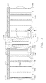
FIG. 1 is a cross-sectional view of an embodiment of a partially assembled acoustic panel. -
FIG. 2 is a cross-sectional view of an embodiment of an acoustic panel. -
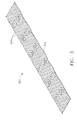
FIG. 3 is a perspective view of an embodiment of a tip mandrel sheet as may be used in manufacturing a component. -
FIG. 4 is a cross-sectional exploded assembly view of a portion of the tip mandrel sheet ofFIG. 3 . -
FIG. 5 is a cross-sectional view of an embodiment detailing manufacture of a face sheet layer. - Referring now to
FIG. 1 , an embodiment of anacoustic panel 100 is provided. The exemplary embodiments of theacoustic panel 100 may be used with, for example, internal surfaces of aircraft engines and more specifically, by way of example, in the fan compartment area of the engine. The acoustic panel is provided with acore layer 102, which may have, for example, a honey-comb cross-sectional geometry extending from a firstcore layer surface 110 toward a secondcore layer surface 108. Other geometries may be used however such as a plurality of cylindrical cross-sections or polygonal cross-sections. The core layer has a thickness which will allow for dissipation of acoustic energy therein. Thecore layer 102 may be formed of various materials including, but not limited to, aluminum or fiberglass coated with phenolic resin. Thecore layer 102 may be disposed between aface sheet layer 104 and aback sheet layer 106. The terms face sheet and back sheet are defined relative to the airflow through the aircraft engine. Theface sheet layer 104 is exposed to or closer to the flow path of air through the aircraft engine, for example, while theback sheet layer 106 is disposed further or away from the flow path of air. Theback sheet layer 106 is preferably bonded to the core layer on aback surface 108 and theface sheet layer 104 is preferably bonded to thecore layer 102 on anopposed face surface 110. Theface sheet layer 104 andback sheet layer 106 generally function as skins for the acoustic panel. - Referring now to
FIGs. 1 and2 , the core layer has one ormore depressions 112 on thecore layer face 110. Thecore layer depressions 112 receive positionally corresponding depressions of theface sheet layer 104. Theface sheet layer 104 has a generally uniform thickness and generally conforms to the one ormore depressions 112 on thecore layer face 110. Theface sheet layer 104 may have an exposedsurface 114, and, within the one or more face sheet depressions, adepression surface 116. A height h1 may exist between the exposedsurface 114 and thedepression surface 116. Ahole 120 may be provided within the one ormore depressions 112 that extends through theback face layer 106 and through thedepression surface 116. Thehole 120 allows for placement of abolt assembly 200 described further herein. - The
face sheet layer 104 may also have a plurality of apertures (not shown) on the exposedsurface 114. The apertures allow sound to pass through theface sheet surface 114 and enter thecore layer 102 for sound damping. The apertures may be randomly sized, shaped and spaced or alternatively may be selectively sized, shaped and spaced, or some combination thereof. - A
bolt assembly 200 may be provided to extend through thehole 120. Thebolt assembly 200 may be provided with abolt 202 and a two-piece bushing 204, 206. The two-piece bushing 204, 206 may be provided with afront piece 204 and aback piece 206. Thebolt 202 may extend through thebushing bolt head 208 abuts thefront piece 204. Thebolt 202 extends into theback piece 206 and, according to one exemplary embodiment, threadably engages theback piece 206. As thebolt 202 is tightened, thefront piece 204 andback piece 206 are squeezed together capturing theface sheet layer 104,core layer 102 andback sheet layer 106. Additionally however, the back piece and front pieces may be affixed with adhesive solely or in addition to the mechanical fastening. Further, thefront piece 204 may be designed to extend through theback piece 206 forming a stand-off on the rear or back side of thepanel 100. - The front piece bushing 202 and
bolt head 208 extend from thedepression surface 116 at a height h2 that is less than the height h1 between thedepression surface 116 and the exposedsurface 114, such that it is countersunk with respect to the exposedsurface 114. Theback piece 206 extends from the opposite side of the composite panel structure at theback sheet layer 106. The resulting assembly provides a two-piecebushing bolt assembly 200 that sandwiches theback sheet layer 106, thecore layer 102, and theface sheet layer 104. Flanges 210 of the front andback pieces bushings face sheet layer 104 andback sheet layer 106, rather than thru any epoxy within thecore layer 102. Atransition surface 122, such as, for example, a taper or fillet, may be provided between the exposedsurface 114 and thedepression surface 116. - The
face sheet layer 104 may be provided with one or more holes or apertures (not shown) on the exposedsurface 114, which may assist in damping acoustic noise. Referring now toFIG. 3 , the face sheet layer 104 (seeFig. 5 ) may be manufactured using apolymer tip mandrel 300. Thetip mandrel 300 may have asurface 302 that is provided with a plurality of tips orprotrusions 304. Thetip mandrel 300 may be formed by a variety of methods, including, for example, injection molding. Further, the tip mandrel may be formed of other materials such as metals or silicone rubber for example. During manufacture of theface sheet 104, thetip mandrel 300 engages theface sheet layer 104 and creating the apertures in theface sheet 104. The apertures allow sound to pass through theface sheet layer 104 and reach thecore layer 102 for damping. - Referring now to
FIGs. 3 and4 , thetip mandrel 300 may also be provided with one ormore holes 306 therethrough that correspond todepressions 112 on theacoustic panel 100. Aboss puck 308 may be heat welded in each of the one ormore holes 306 such that it protrudes above thesurface 302 that is provided with a plurality oftips 304. According to one embodiment, the boss puck may be plastic or alternatively may be metallic or even further alternative materials. Theboss puck 308 may also be adhered, affixed or loosely positioned in place for use during manufacture as alternatives to the heat welding. Additionally, theboss puck 308 may extend to a height greater than that of thetips 304. During manufacture of theface sheet layer 104, theboss puck 308 will form thedepression surface 116 and transition surfaces 122 (FIG. 2 ) in theface sheet layer 104. - Referring now to
FIG. 5 , theface sheet layer 104 may be manufactured of a preimpregnated fiberglass or carbon material. This material is applied to thetip mandrel 300 and a siliconerubber caul sheet 310 is placed upon that. The siliconerubber caul sheet 310 is provided with adepression 312 that generally mimics that of the one ormore depressions 112 on the above-discussedcore layer 102. Asilicone rubber sheet 314 is placed on thecaul sheet 310 and a secondsilicone rubber sheet 316 is placed on the opposite side of thetip mandrel 300. This assembly is placed between twoplatens 320 to compress the materials and cure theface sheet 104. The siliconerubber caul sheet 310 provides an equal application of pressure when theface sheet layer 104 is formed betweenplatens 320. Additionally, thedepression 312 in thesilicone caul sheet 312 provides an allowance for material moved in creating the depression of theface sheet layer 104. Theface sheet 104 is now removed having a preformed contour that matches adepression 112 on thecore layer 102. - Referring back to
FIGs. 1 and2 , thecore layer 102 is provided withdepressions 112 machined thereon. Thedepressions 112 may be formed in a variety of manners including, but not limited to, grinding. - Once the various components are formed, they are assembled to form the composite acoustic panel. The
back sheet layer 106 may be bonded to aback surface 108 of thecore layer 102, and may preferably be bonded with an adhesive 124 therebetween. For example, an epoxy film adhesive may be utilized to combine theback sheet layer 106 and thecore layer 102. Theface sheet layer 104 may also be bonded to thefront surface 110 of thecore layer 102, either at the same time or after theback sheet layer 106 is bonded, and may preferably be bonded with anadhesive layer 126 therebetween. Ahole 120 may be machined through all layers in each of the one ormore depressions 112 on theassembly 100. The at least onehole 120 may be formed before the layers are combined or after the panel is formed. Thebolt assembly 200 may then be inserted in thehole 112 according to the exemplary embodiment ofFIG. 2 . - The foregoing written description of structures and methods has been presented for purposes of illustration. Examples are used to disclose the embodiments, including the best mode, and also to enable any person skilled in the art to practice the apparatus and/or method, including making and using any devices or systems and performing any incorporated methods. These examples are not intended to be exhaustive or to limit the disclosure to the precise steps and/or forms disclosed, and many modifications and variations are possible in light of the above teaching. Features described herein may be combined in any combination. Steps of a method described herein may be performed in any sequence that is physically possible. The patentable scope of the disclosure is defined by the appended claims, and may include other examples that occur to those skilled in the art. Such other examples are intended to be within the scope of the claims if they have structural elements that do not differ from the literal language of the claims, or if they include equivalent structural elements with insubstantial differences from the literal languages of the claims.
- Various aspects and embodiments of the invention are indicated in the following clauses:
- 1. An acoustic panel comprising:
- a composite laminate panel having a back sheet layer, a face sheet layer, and a core layer disposed between said back sheet layer and said face sheet layer;
- wherein said core layer has one or more depressions at an interface between said core layer and said face sheet layer;
- wherein said face sheet layer conforms to said one or more core layer depressions, and has a depression surface within said one or more depressions and a face surface at all
- other locations not within said one or more depressions; and wherein said face sheet layer has a generally uniform thickness across said face surface and said depression surface;
- wherein said one or more depressions have a depth as measured from said depression surfaces and said face surface;
- a hole located in said depression surface and through said one or more depressions extending through core layer;
- a bolt assembly extending through said hole, wherein said bolt assembly extends above said depressions surface at a height that is less than said depth of said one or more depressions.
- 2. The acoustic panel of clause 1 wherein said back sheet layer is bonded to said core layer.
- 3. The acoustic panel of clause 1 wherein said face sheet layer is bonded to said core layer.
- 4. The acoustic panel of clause 1 wherein said bolt assembly comprises a bolt and one or more bushings.
- 5. The acoustic panel of clause 1 wherein said face sheet layer has a plurality of apertures within said face surface.
- 6. The acoustic panel of clause 1 wherein said depression surface is generally flat.
- 7. The acoustic panel of clause 1 further comprising transition surfaces between said face surface and said depression surfaces.
- 8. The acoustic panel of Clause 1 wherein said core layer has a honeycomb cross-section extending between said face sheet layer and said back sheet layer.
- 9. An acoustic panel comprising:
- a composite laminate panel having:
- a back sheet layer which may be positioned opposite an air flow path;
- a core layer bonded adjacent said back sheet layer, said core layer acoustically damping noise, said core layer having at least one depression on a side of said core layer adjacent a face sheet layer;
- said face sheet layer bonded to said core layer and capable of being positioned adjacent an air flow path, said face sheet layer having a face sheet surface and at least one depression surface, said at least one depression surface positionally corresponding to said at least one depression, said depression surface having a depression surface hole aligned with a depression hole extending through said core layer;
- a bolt assembly including a bolt and at least one bushing extending through said hole of said face sheet layer, said at least one bushing capturing said back sheet layer, said core layer and said face sheet layer, a portion of said bolt assembly disposed in said depression surface having a height which is less than a height between said face sheet surface and said depression surface.
- a composite laminate panel having:
- 10. The acoustic panel of Clause 9, said panel further comprising a hole in said back sheet layer.
- 11. The acoustic panel of Clause 9 further comprising a plurality of apertures in said face sheet for acoustical treatment.
- 12. The acoustic panel of Clause 9, said at least one bushing comprising a front piece engaging said face sheet layer and a back piece engaging said back sheet layer.
- 13. The acoustic panel of
Clause 12, said bolt extending through said front piece and engaging said back piece. - 14. A method of forming an acoustic panel, comprising the steps of:
- forming a face sheet layer having an outermost surface, at least one depression surface and a hole;
- forming at least one depression in a core layer, said position of said depression surface corresponding to said position of said depression of said core layer;
- bonding a face sheet layer of a composite mixture to a core layer;
- bonding a back sheet layer to said core layer;
- positioning a bolt assembly through said acoustic panel wherein said depression surface and said outermost surface define a first height, and a bolt head and a bushing of said bolt assembly define a second height;
- and further wherein said first height is greater than said second height.
- 15. The method of Clause 14 further comprising bonding said bolt assembly to at least one of said face sheet and said back sheet.
- 16. The method of Clause 14 said forming said face sheet layer comprising pressing said face sheet layer with a tip mandrel having a boss puck.
- 17. The method of Clause 16 further comprising positioning a silicone caul sheet on said face sheet opposite said tip mandrel.
- 18. The method of Clause 17 further comprising positioning a silicone sheet on said silicone caul sheet opposite said face sheet layer.
- 19. The method of Clause 18 further comprising a silicone sheet adjacent disposed between said tip mandrel and a platen.
- 20. The method of Clause 14 further comprising forming said face sheet between first and second platens.
Claims (15)
- An acoustic panel (100) comprising:a composite laminate panel having a back sheet layer (106), a face sheet layer (104), and a core layer (102) disposed between said back sheet layer and said face sheet layer;wherein said core layer (102) has one or more depressions (112) at an interface between said core layer and said face sheet layer;wherein said face sheet layer (104) conforms to said one or more core layer (112) depressions, and has a depression surface (116) within said one or more depressions (112) and a face surface (114) at all other locations not within said one or more depressions (112); and wherein said face sheet layer (104) has a generally uniform thickness across said face surface (114) and said depression surface (116);wherein said one or more depressions (112) have a depth (h1) as measured from said depression surfaces (116) and said face surface (114);a hole (120) located in said depression surface (116) and through said one or more depressions extending through core layer (102);a bolt assembly (200) extending through said hole (120), wherein said bolt assembly extends above said depression surface (116) at a height (h2) that is less than said depth (h1) of said one or more depressions (112).
- The acoustic panel (100) of claim 1, wherein said back sheet layer (106) is bonded to said core layer (102).
- The acoustic panel of either of claim 1 or 2, wherein said face sheet layer (104) is bonded to said core layer (102).
- The acoustic panel (100) of any preceding claim, wherein said bolt assembly (202) comprises a bolt and one or more bushings (204, 206).
- The acoustic panel (100) of any preceding claim, wherein said face sheet layer (104) has a plurality of apertures within said face surface (114).
- The acoustic panel (100) of any preceding claim, wherein said depression surface (116) is generally flat.
- The acoustic panel (100) of any preceding claim, further comprising transition surfaces (122) between said face surface (114) and said depression surfaces (116).
- The acoustic panel (100) of any preceding claim, wherein said core layer (102) has a honeycomb cross-section extending between said face sheet layer (104) and said back sheet layer (106).
- A method of forming an acoustic panel (100), comprising the steps of:forming a face sheet layer (104) having an outermost surface (114), at least one depression surface (116) and a hole (120);forming at least one depression (112) in a core layer (102), said position of said depression surface (116) corresponding to said position of said depression (112) of said core layer (102);bonding a face sheet layer (104) of a composite mixture to a core layer (102);bonding a back sheet layer (106) to said core layer (102);positioning a bolt assembly (200) through said acoustic panel (100) wherein said depression surface (116) and said outermost surface (114) define a first height (h1), and a bolt head (208) and a bushing (204) of said bolt assembly define a second height (h2);and further wherein said first height (h1) is greater than said second height (h2).
- The method of Claim 9, further comprising bonding said bolt assembly (200)to at least one of said face sheet (104) and said back sheet (106).
- The method of either of Claim 9 or 10, said forming said face sheet layer (104) comprising pressing said face sheet layer (104) with a tip mandrel (300) having a boss puck (308).
- The method of any one of Claims 9 to 11, further comprising positioning a silicone caul sheet (310) on said face sheet layer (104) opposite said tip mandrel (300).
- The method of Claim 12, further comprising positioning a silicone sheet (314) on said silicone caul sheet (310) opposite said face sheet layer (104).
- The method of Claim 13, further comprising a silicone sheet (316) adjacent disposed between said tip mandrel (300) and a platen (320).
- The method of any of Claims 9 to 14, further comprising forming said face sheet (104) between first and second platens (320).
Applications Claiming Priority (1)
| Application Number | Priority Date | Filing Date | Title |
|---|---|---|---|
| US13/371,029 US8763753B2 (en) | 2012-02-10 | 2012-02-10 | Acoustic panel and method of forming |
Publications (2)
| Publication Number | Publication Date |
|---|---|
| EP2626536A2 true EP2626536A2 (en) | 2013-08-14 |
| EP2626536A3 EP2626536A3 (en) | 2017-09-20 |
Family
ID=47747415
Family Applications (1)
| Application Number | Title | Priority Date | Filing Date |
|---|---|---|---|
| EP13154691.3A Withdrawn EP2626536A3 (en) | 2012-02-10 | 2013-02-08 | Acoustic panel and method of forming |
Country Status (4)
| Country | Link |
|---|---|
| US (1) | US8763753B2 (en) |
| EP (1) | EP2626536A3 (en) |
| JP (1) | JP2013164590A (en) |
| CA (1) | CA2804532A1 (en) |
Cited By (1)
| Publication number | Priority date | Publication date | Assignee | Title |
|---|---|---|---|---|
| WO2018002103A1 (en) * | 2016-06-27 | 2018-01-04 | Amina Technologies Limited | Speaker panel |
Families Citing this family (11)
| Publication number | Priority date | Publication date | Assignee | Title |
|---|---|---|---|---|
| FR2959726B1 (en) * | 2010-05-07 | 2013-05-31 | Aircelle Sa | ASSEMBLY FOR PROPULSIVE AIRCRAFT SYSTEM |
| EP2725161B1 (en) * | 2012-10-24 | 2015-10-14 | Saint-Gobain Ecophon AB | Sound absorbing module and a suspended ceiling comprising the same |
| US11092077B2 (en) * | 2018-03-28 | 2021-08-17 | Pratt & Whitney Canada Corp. | Aircraft component and method of manufacture |
| US11155047B2 (en) * | 2018-10-08 | 2021-10-26 | Textron Innovations Inc. | Caul body and a method for forming a composite structure |
| WO2020117822A1 (en) * | 2018-12-03 | 2020-06-11 | Armstrong World Industries, Inc. | Acoustical building panel, monolithic surface covering system incorporating an acoustical building panel, and methods of forming and installing the same |
| IT201900004761A1 (en) * | 2019-03-29 | 2020-09-29 | Leonardo Spa | Manufacturing process of a sound-absorbing panel with a sandwich structure to reduce the sound impact of an aircraft engine |
| US11313324B2 (en) * | 2019-04-12 | 2022-04-26 | Rolls-Royce Corporation | Systems and methods of acoustic dampening in a gas turbine engine |
| US11680542B2 (en) * | 2020-02-03 | 2023-06-20 | Rohr, Inc. | Thrust reverser door and method for making same |
| CA3178013A1 (en) | 2020-05-12 | 2021-11-18 | Raymond Disantis | Blind fastener |
| CA3186685A1 (en) | 2020-07-20 | 2022-01-27 | Raymond Disantis | Rivetless nut plate |
| US12060906B2 (en) | 2021-08-06 | 2024-08-13 | Bpc Lg 2, Llc | Panel fastener |
Family Cites Families (34)
| Publication number | Priority date | Publication date | Assignee | Title |
|---|---|---|---|---|
| US2607447A (en) * | 1946-02-26 | 1952-08-19 | Us Plywood Corp | Fastener |
| US2957196A (en) * | 1958-11-25 | 1960-10-25 | Shur Lok Corp | Bolt and stud spacer for lightweight sandwich panels |
| US3443473A (en) * | 1967-08-01 | 1969-05-13 | Goodrich Co B F | Axially collapsible fastener |
| US3451181A (en) * | 1967-08-29 | 1969-06-24 | Robert Neuschotz | Honeycomb structures containing threaded inserts |
| US3526072A (en) * | 1968-03-29 | 1970-09-01 | James R Campbell | Load distributing system for panels incorporating honeycomb core |
| US3977146A (en) * | 1974-12-18 | 1976-08-31 | Standard Pressed Steel Co. | Fastener bushing |
| US4106587A (en) | 1976-07-02 | 1978-08-15 | The United States Of America As Represented By The Administrator Of The National Aeronautics And Space Administration | Sound-suppressing structure with thermal relief |
| US4671841A (en) | 1986-01-06 | 1987-06-09 | Rohr Industries, Inc. | Method of making an acoustic panel with a triaxial open-weave face sheet |
| JPH0740433Y2 (en) * | 1989-10-09 | 1995-09-20 | 河西工業株式会社 | Insulator dash mounting structure |
| US5275529A (en) * | 1992-03-16 | 1994-01-04 | General Electric Company | Sandwich panel joint |
| US5498127A (en) | 1994-11-14 | 1996-03-12 | General Electric Company | Active acoustic liner |
| US6123171A (en) | 1999-02-24 | 2000-09-26 | Mcnett; Christopher P. | Acoustic panels having plural damping layers |
| US6766639B2 (en) | 2002-09-30 | 2004-07-27 | United Technologies Corporation | Acoustic-structural LPC splitter |
| US6722466B1 (en) | 2002-10-07 | 2004-04-20 | General Electric Company | Acoustic blanket for machinery and method for attenuating sound |
| US7047725B2 (en) | 2003-05-28 | 2006-05-23 | Rohr, Inc. | Assembly and method for aircraft engine noise reduction |
| US7090165B2 (en) | 2003-06-02 | 2006-08-15 | Rolls-Royce Plc | Aeroengine nacelle |
| US7588212B2 (en) | 2003-07-08 | 2009-09-15 | Rohr Inc. | Method and apparatus for noise abatement and ice protection of an aircraft engine nacelle inlet lip |
| US6920958B2 (en) | 2003-10-17 | 2005-07-26 | The Boeing Company | Annular acoustic panel |
| GB2407344B (en) | 2003-10-22 | 2006-02-22 | Rolls Royce Plc | A liner for a gas turbine engine casing |
| GB2407343B (en) | 2003-10-22 | 2006-04-19 | Rolls Royce Plc | An acoustic liner for a gas turbine engine casing |
| US20060137294A1 (en) * | 2004-01-13 | 2006-06-29 | Waits Jr Bobby L | Expanded fastener for a honeycomb structure and method of assembly |
| GB2429043B (en) | 2005-08-13 | 2008-02-13 | Rolls Royce Plc | Clip |
| FR2891325B1 (en) * | 2005-09-28 | 2007-10-26 | Airbus France Sas | DEVICE FOR FIXING A LIGHT PANEL ON A SUPPORT |
| US7923668B2 (en) | 2006-02-24 | 2011-04-12 | Rohr, Inc. | Acoustic nacelle inlet lip having composite construction and an integral electric ice protection heater disposed therein |
| GB0610271D0 (en) | 2006-05-24 | 2006-07-05 | Rolls Royce Plc | A gas turbine engine casing |
| US7503425B2 (en) | 2006-10-02 | 2009-03-17 | Spirit Aerosystems, Inc. | Integrated inlet attachment |
| GB2443830B (en) | 2006-11-15 | 2010-01-20 | Rolls Royce Plc | Cowling arrangement |
| DE202007009063U1 (en) * | 2007-06-28 | 2007-09-06 | Ejot Holding Gmbh & Co. Kg | Fixing element for fixing sandwich element to substructure has one-piece oblong sleeve of stainless steel with outwardly protruding collar at upper end that can be extended by disk-shaped element |
| GB0713526D0 (en) | 2007-07-12 | 2007-08-22 | Rolls Royce Plc | An acoustic panel |
| US20100206664A1 (en) | 2007-07-12 | 2010-08-19 | Rolls-Royce Plc | Acoustic panel |
| FR2924685B1 (en) * | 2007-12-11 | 2010-03-19 | Airbus France | PARAFOUDRE AND AIRCRAFT SYSTEM COMPRISING SUCH A SYSTEM. |
| GB2459844B (en) | 2008-05-06 | 2011-01-19 | Rolls Royce Plc | Fan section |
| US8028802B2 (en) | 2008-06-30 | 2011-10-04 | General Electric Company | Method and system for damped acoustic panels |
| US8294059B2 (en) | 2008-11-26 | 2012-10-23 | Mra Systems, Inc. | Process for producing through-holes in sheet members |
-
2012
- 2012-02-10 US US13/371,029 patent/US8763753B2/en not_active Expired - Fee Related
-
2013
- 2013-01-31 CA CA2804532A patent/CA2804532A1/en not_active Abandoned
- 2013-02-08 EP EP13154691.3A patent/EP2626536A3/en not_active Withdrawn
- 2013-02-08 JP JP2013022781A patent/JP2013164590A/en not_active Ceased
Non-Patent Citations (1)
| Title |
|---|
| None |
Cited By (4)
| Publication number | Priority date | Publication date | Assignee | Title |
|---|---|---|---|---|
| WO2018002103A1 (en) * | 2016-06-27 | 2018-01-04 | Amina Technologies Limited | Speaker panel |
| GB2551723B (en) * | 2016-06-27 | 2018-11-28 | Amina Tech Limited | Speaker Panel |
| US10893344B2 (en) | 2016-06-27 | 2021-01-12 | Amina Technologies Limited | Speaker panel |
| US11582540B2 (en) | 2016-06-27 | 2023-02-14 | Amina Technologies Limited | Speaker panel |
Also Published As
| Publication number | Publication date |
|---|---|
| EP2626536A3 (en) | 2017-09-20 |
| US8763753B2 (en) | 2014-07-01 |
| US20130206503A1 (en) | 2013-08-15 |
| JP2013164590A (en) | 2013-08-22 |
| CA2804532A1 (en) | 2013-08-10 |
Similar Documents
| Publication | Publication Date | Title |
|---|---|---|
| US8763753B2 (en) | Acoustic panel and method of forming | |
| EP2816242B1 (en) | Honeycomb cores with splice joints and methods of assembling honeycomb cores | |
| US7921966B2 (en) | Linear acoustic liner | |
| US6513757B1 (en) | Wing of composite material and method of fabricating the same | |
| US9162747B2 (en) | Method for manufacturing a sound attenuation panel | |
| US7334997B2 (en) | Hybrid blisk | |
| US10322563B2 (en) | Panel-insert assembly and method | |
| CN113002074B (en) | Structural single degree of freedom panel acoustic liner | |
| US20110254196A1 (en) | Method for making an acoustic attentuation panel, in particular for aeronautics | |
| JP2014188995A (en) | Repair method for part to be repaired and repair result obtained by the repair | |
| US10005267B1 (en) | Formation of complex composite structures using laminate templates | |
| RU2731247C2 (en) | Sandwich panel-type sound-absorbing panel repair methods and set and sandwich-type sound-proofing panel repair kits for repair thereof | |
| JP2013164590A5 (en) | ||
| US20170297729A1 (en) | Panel and insert for corner radii | |
| JP2014504564A (en) | Method and apparatus for compressing a composite radius | |
| US7484593B2 (en) | Acoustic structure and method of manufacturing thereof | |
| JP2001030997A (en) | Compound material wing, and its manufacture | |
| EP3392027B1 (en) | Systems and methods for assembling elongate composite structures | |
| EP3199336A1 (en) | Sandwich panel assembly and method | |
| JP5263001B2 (en) | Skeletal structure | |
| JP4338838B2 (en) | Method for integrally forming composite wings | |
| EP3616864A1 (en) | Method and system for forming holes within an uncured composite sheet, and method for forming a composite structure | |
| JP2002347149A (en) | Composite-material honeycomb sandwich structure and manufacturing method therefor | |
| JP2021050672A (en) | Suction duct |
Legal Events
| Date | Code | Title | Description |
|---|---|---|---|
| PUAI | Public reference made under article 153(3) epc to a published international application that has entered the european phase |
Free format text: ORIGINAL CODE: 0009012 |
|
| AK | Designated contracting states |
Kind code of ref document: A2 Designated state(s): AL AT BE BG CH CY CZ DE DK EE ES FI FR GB GR HR HU IE IS IT LI LT LU LV MC MK MT NL NO PL PT RO RS SE SI SK SM TR |
|
| AX | Request for extension of the european patent |
Extension state: BA ME |
|
| PUAL | Search report despatched |
Free format text: ORIGINAL CODE: 0009013 |
|
| AK | Designated contracting states |
Kind code of ref document: A3 Designated state(s): AL AT BE BG CH CY CZ DE DK EE ES FI FR GB GR HR HU IE IS IT LI LT LU LV MC MK MT NL NO PL PT RO RS SE SI SK SM TR |
|
| AX | Request for extension of the european patent |
Extension state: BA ME |
|
| RIC1 | Information provided on ipc code assigned before grant |
Ipc: F02C 7/24 20060101AFI20170811BHEP |
|
| STAA | Information on the status of an ep patent application or granted ep patent |
Free format text: STATUS: THE APPLICATION IS DEEMED TO BE WITHDRAWN |
|
| 18D | Application deemed to be withdrawn |
Effective date: 20180321 |