EP2626515B1 - Tandem-Schaufelgruppenanordnung - Google Patents
Tandem-Schaufelgruppenanordnung Download PDFInfo
- Publication number
- EP2626515B1 EP2626515B1 EP12154944.8A EP12154944A EP2626515B1 EP 2626515 B1 EP2626515 B1 EP 2626515B1 EP 12154944 A EP12154944 A EP 12154944A EP 2626515 B1 EP2626515 B1 EP 2626515B1
- Authority
- EP
- European Patent Office
- Prior art keywords
- blade
- curvature
- group assembly
- group
- blade group
- Prior art date
- Legal status (The legal status is an assumption and is not a legal conclusion. Google has not performed a legal analysis and makes no representation as to the accuracy of the status listed.)
- Active
Links
Images

Classifications
-
- F—MECHANICAL ENGINEERING; LIGHTING; HEATING; WEAPONS; BLASTING
- F01—MACHINES OR ENGINES IN GENERAL; ENGINE PLANTS IN GENERAL; STEAM ENGINES
- F01D—NON-POSITIVE DISPLACEMENT MACHINES OR ENGINES, e.g. STEAM TURBINES
- F01D5/00—Blades; Blade-carrying members; Heating, heat-insulating, cooling or antivibration means on the blades or the members
- F01D5/02—Blade-carrying members, e.g. rotors
- F01D5/022—Blade-carrying members, e.g. rotors with concentric rows of axial blades
-
- F—MECHANICAL ENGINEERING; LIGHTING; HEATING; WEAPONS; BLASTING
- F01—MACHINES OR ENGINES IN GENERAL; ENGINE PLANTS IN GENERAL; STEAM ENGINES
- F01D—NON-POSITIVE DISPLACEMENT MACHINES OR ENGINES, e.g. STEAM TURBINES
- F01D5/00—Blades; Blade-carrying members; Heating, heat-insulating, cooling or antivibration means on the blades or the members
- F01D5/12—Blades
- F01D5/14—Form or construction
- F01D5/141—Shape, i.e. outer, aerodynamic form
- F01D5/146—Shape, i.e. outer, aerodynamic form of blades with tandem configuration, split blades or slotted blades
-
- F—MECHANICAL ENGINEERING; LIGHTING; HEATING; WEAPONS; BLASTING
- F01—MACHINES OR ENGINES IN GENERAL; ENGINE PLANTS IN GENERAL; STEAM ENGINES
- F01D—NON-POSITIVE DISPLACEMENT MACHINES OR ENGINES, e.g. STEAM TURBINES
- F01D17/00—Regulating or controlling by varying flow
- F01D17/10—Final actuators
- F01D17/12—Final actuators arranged in stator parts
- F01D17/14—Final actuators arranged in stator parts varying effective cross-sectional area of nozzles or guide conduits
- F01D17/16—Final actuators arranged in stator parts varying effective cross-sectional area of nozzles or guide conduits by means of nozzle vanes
- F01D17/162—Final actuators arranged in stator parts varying effective cross-sectional area of nozzles or guide conduits by means of nozzle vanes for axial flow, i.e. the vanes turning around axes which are essentially perpendicular to the rotor centre line
-
- F—MECHANICAL ENGINEERING; LIGHTING; HEATING; WEAPONS; BLASTING
- F01—MACHINES OR ENGINES IN GENERAL; ENGINE PLANTS IN GENERAL; STEAM ENGINES
- F01D—NON-POSITIVE DISPLACEMENT MACHINES OR ENGINES, e.g. STEAM TURBINES
- F01D9/00—Stators
- F01D9/02—Nozzles; Nozzle boxes; Stator blades; Guide conduits, e.g. individual nozzles
- F01D9/04—Nozzles; Nozzle boxes; Stator blades; Guide conduits, e.g. individual nozzles forming ring or sector
- F01D9/041—Nozzles; Nozzle boxes; Stator blades; Guide conduits, e.g. individual nozzles forming ring or sector using blades
-
- F—MECHANICAL ENGINEERING; LIGHTING; HEATING; WEAPONS; BLASTING
- F04—POSITIVE - DISPLACEMENT MACHINES FOR LIQUIDS; PUMPS FOR LIQUIDS OR ELASTIC FLUIDS
- F04D—NON-POSITIVE-DISPLACEMENT PUMPS
- F04D29/00—Details, component parts, or accessories
- F04D29/26—Rotors specially for elastic fluids
- F04D29/32—Rotors specially for elastic fluids for axial flow pumps
- F04D29/321—Rotors specially for elastic fluids for axial flow pumps for axial flow compressors
- F04D29/324—Blades
-
- F—MECHANICAL ENGINEERING; LIGHTING; HEATING; WEAPONS; BLASTING
- F04—POSITIVE - DISPLACEMENT MACHINES FOR LIQUIDS; PUMPS FOR LIQUIDS OR ELASTIC FLUIDS
- F04D—NON-POSITIVE-DISPLACEMENT PUMPS
- F04D29/00—Details, component parts, or accessories
- F04D29/40—Casings; Connections of working fluid
- F04D29/52—Casings; Connections of working fluid for axial pumps
- F04D29/54—Fluid-guiding means, e.g. diffusers
- F04D29/541—Specially adapted for elastic fluid pumps
- F04D29/542—Bladed diffusers
-
- F—MECHANICAL ENGINEERING; LIGHTING; HEATING; WEAPONS; BLASTING
- F04—POSITIVE - DISPLACEMENT MACHINES FOR LIQUIDS; PUMPS FOR LIQUIDS OR ELASTIC FLUIDS
- F04D—NON-POSITIVE-DISPLACEMENT PUMPS
- F04D29/00—Details, component parts, or accessories
- F04D29/40—Casings; Connections of working fluid
- F04D29/52—Casings; Connections of working fluid for axial pumps
- F04D29/54—Fluid-guiding means, e.g. diffusers
- F04D29/541—Specially adapted for elastic fluid pumps
- F04D29/542—Bladed diffusers
- F04D29/544—Blade shapes
-
- F—MECHANICAL ENGINEERING; LIGHTING; HEATING; WEAPONS; BLASTING
- F04—POSITIVE - DISPLACEMENT MACHINES FOR LIQUIDS; PUMPS FOR LIQUIDS OR ELASTIC FLUIDS
- F04D—NON-POSITIVE-DISPLACEMENT PUMPS
- F04D29/00—Details, component parts, or accessories
- F04D29/40—Casings; Connections of working fluid
- F04D29/52—Casings; Connections of working fluid for axial pumps
- F04D29/54—Fluid-guiding means, e.g. diffusers
- F04D29/56—Fluid-guiding means, e.g. diffusers adjustable
- F04D29/563—Fluid-guiding means, e.g. diffusers adjustable specially adapted for elastic fluid pumps
-
- F—MECHANICAL ENGINEERING; LIGHTING; HEATING; WEAPONS; BLASTING
- F05—INDEXING SCHEMES RELATING TO ENGINES OR PUMPS IN VARIOUS SUBCLASSES OF CLASSES F01-F04
- F05D—INDEXING SCHEME FOR ASPECTS RELATING TO NON-POSITIVE-DISPLACEMENT MACHINES OR ENGINES, GAS-TURBINES OR JET-PROPULSION PLANTS
- F05D2240/00—Components
- F05D2240/20—Rotors
- F05D2240/30—Characteristics of rotor blades, i.e. of any element transforming dynamic fluid energy to or from rotational energy and being attached to a rotor
- F05D2240/301—Cross-sectional characteristics
-
- Y—GENERAL TAGGING OF NEW TECHNOLOGICAL DEVELOPMENTS; GENERAL TAGGING OF CROSS-SECTIONAL TECHNOLOGIES SPANNING OVER SEVERAL SECTIONS OF THE IPC; TECHNICAL SUBJECTS COVERED BY FORMER USPC CROSS-REFERENCE ART COLLECTIONS [XRACs] AND DIGESTS
- Y02—TECHNOLOGIES OR APPLICATIONS FOR MITIGATION OR ADAPTATION AGAINST CLIMATE CHANGE
- Y02T—CLIMATE CHANGE MITIGATION TECHNOLOGIES RELATED TO TRANSPORTATION
- Y02T50/00—Aeronautics or air transport
- Y02T50/60—Efficient propulsion technologies, e.g. for aircraft
Definitions
- the invention relates to a blade group arrangement according to the preamble of claim 1 and a turbomachine.
- the maximum deflection of a row of blades of a turbomachine and thus its aerodynamic load capacity is limited on the one hand by a flow separation on the blade profile. On the other hand, the maximum deflection is limited by a separation of a boundary layer flow on the hubs and side walls on the housing.
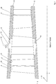
- two or more groups of blades are known. Exemplary double blade row groups are in Figure 1 shown. Further exemplary two-fold blade row groups are in the DE 10 2009 013 399 A1 as well as in the EP 0 823 540 B1 described.
- the blade row groups shown are a rotor-side blade row group 2, a stator-side blade row group 4 and an adjustable blade row group 6.
- the blade row groups 2, 4, 6 are each formed by a multiplicity of blade group arrangements which, as known tandem blade arrangements, each have two blades 8, 10 arranged one behind the other in the flow direction are.
- the front blades 8 and the rear blades 10 each form a row of blades.
- the rotor-side blade row group 2 and the stator-side blade row group 4 are each fixedly connected to a hub 12 or to a housing 14, the tip between the blade tips Blades 8, 10 and the housing 14 or the hub 12, a sealing gap 16 is formed.
- the blades 8, 10 of the adjustable blade row group 6 are each supported at the end on a turntable 18, 20 and can be pivoted about a transverse axis 22 according to the rotary arrow.
- the blades 8, 10 can be spaced apart from one another in the axial direction (rotor-side blade row group 2 and adjustable blade row group 6) or form an overlap region 24 (stator-side blade row group 4).
- the object of the invention is to provide a vane group arrangement for a turbomachine for forming a vane row group, which enables high efficiency. Furthermore, it is an object of the invention to provide a turbomachine with a high degree of efficiency.
- a vane group arrangement according to the invention for a turbomachine for forming a vane row group has a front vane and a rear vane, which are arranged offset to one another in the axial and circumferential direction and form an overlap region which runs between a pressure side of the front vane and between a suction side of the rear vane.
- the blades have a convergent shape in the overlap region with a contraction ratio between an entry area and an exit area of 1,2 1.2. It has also been shown that a maximum contraction ratio should not be exceeded in order to achieve high efficiency.
- the maximum contraction ratio is 2.8, so that the contraction ratio ranges from 1.2 to 2.8.
- the contraction ratio has a value of 1.7.
- a suction side of the rear blade has a greater curvature downstream of the outlet surface than upstream of the outlet surface.
- the curvature preferably has a maximum of 1.6 times to 1.7 times an average curvature of the suction side of the rear blade.
- the maximum curvature is about 5% to 25% relative skeleton line length behind the exit surface of the overlap area.
- a preferred turbomachine has at least one blade row group with a plurality of blade group arrangements according to the invention. Such a turbomachine is characterized by a high degree of efficiency and thus a high level of efficiency.
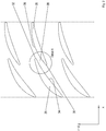
- Figure 2 shows a plan view of a peripheral portion of a blade row group of a turbomachine, for example a stationary gas turbine or an aircraft engine.
- the vane row group is formed by a multiplicity of vane group arrangements such as tandem vane arrangements, each of which has two vanes 26 and 28 arranged offset with respect to one another in the axial direction and circumferential direction.
- the blades 26, 28 each form a row of blades and each have a radially extending front edge 30 and a radially extending rear edge 32.
- the front blades 26 are arranged with their rear edges 32 downstream of the front edges 30 of the rear blades 28, which means between pressure sides 34 of the front blades 26 and suction sides 36 of the rear blades 28, an overlap area 38 is formed.
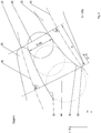
- the overlap region 38 has an overlap degree O, which is determined by falling a solder 40 from the rear edge 32 of the front blade 26 onto a skeleton line 42 of the rear blade 28.
- the distance between the front edge 30 and the intersection between the solder 40 and the skeleton line 42 of the rear blade 28 is the degree of coverage O.
- the degree of coverage O is determined positively from the front edge 30 in the direction of the rear blade 28.
- each coverage area has a pressure-side and a suction-side coverage degree O, which are determined separately for the pressure side 34 and the suction side 36.
- the degree of coverage on the pressure side (not scaled) is determined by falling a solder 44 from the front edge 30 of the rear blade 28 onto a skeleton line 46 of the front blade 26.
- the distance between the rear edge 32 of the front blade 26 and the intersection between the solder 44 and the skeleton line 46 is the degree of coverage on the suction side.
- the coverage area 38 has a convergent surface course. Ie the pressure side 34 and the suction side 36 run in the direction of flow tapering towards each other. Since a two-dimensional view is taken, a cross-sectional area D min is always to be understood as the blade spacing multiplied by a radial unit height.
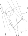
- the overlap area 38 has an entry area D min, 1 , which is defined as the smallest distance (distance AB) between the front edges 30 of the rear blades 28 and the pressure sides 34 of the front blades 26.
- the overlap area 38 has a smaller outlet area or narrow area D min, 2 , which is described by the smallest distance (distance CD) between the suction sides 36 of the rear blades 28 and the pressure sides 34 of the front blade 26.
- a contraction ratio KV with a value of KV 1.7 is preferred.
- FIG. 5 A preferred suction-side profile curvature of the rear blades 28 is shown. As shown in the diagram at the bottom left, each blade surface has a curvature profile which is plotted as curvature k over, for example, the running coordinate s along the skeleton line 42. In this case, only the profile-side curvature of the rear blades 28 between 2% and 98% of the skeleton line length is primarily considered.
- An average curvature k m can be determined for the suction side 36 of the rear blades 28.
- the position of the maximum curvature k max becomes, as in top right in Figure 5 illustrated as described below:
- a distance of the exit surface s (D min, 2 ) from the front edge 30 of the rear blade 28 along the skeleton line is shown 42 determined.
- a distance of the maximum suction side curvature s (k max ) from the leading edge 30 along the skeleton line 42 is determined by falling a solder 50 from the point of the maximum suction side curvature P (k max ) onto the skeleton line 42.
- the maximum curvature lies about 5% to 25% relative skeleton line length behind the narrow surface D min, 2 .
- s ( k Max ) s ( D min , 2nd ) + 0.05 ... 0.25 ⁇ ( s ( HK ( i + 1 ) ) - s ( VK ( i + 1 ) ) ) or .
- s ( k Max ) s ( D min , 2nd ) + 0.05 ... 0.25 ⁇ ( s ( 52 ) - s ( 30th ) ) .
- s k Max s D min , 2nd + 0.15 ⁇ s HK i + 1 - s VK i + 1
- a vane group arrangement for a turbomachine for forming a vane row group, a front vane with a rear vane each forming an overlap region that has a contraction ratio that ranges from 1.2 to 2.8, and a turbomachine with one Contraction ratio between a front and a rear blade.
Landscapes
- Engineering & Computer Science (AREA)
- Mechanical Engineering (AREA)
- General Engineering & Computer Science (AREA)
- Physics & Mathematics (AREA)
- Geometry (AREA)
- Fluid Mechanics (AREA)
- Structures Of Non-Positive Displacement Pumps (AREA)
Description
- Die Erfindung betrifft eine Schaufelgruppenanordnung nach dem Oberbegriff des Patentanspruchs 1 sowie eine Strömungsmaschine.
- Die maximale Umlenkung einer Schaufelreihe einer Strömungsmaschine und somit deren aerodynamische Belastbarkeit ist zum einen durch eine Strömungsablösung am Schaufelprofil begrenzt. Zum anderen wird die maximale Umlenkung durch eine Ablösung einer Grenzschichtströmung an Naben und gehäuseseitigen Seitenwänden begrenzt. Zur Erhöhung der Umlenkfähigkeit von Schaufelreihen sind zwei- und mehrfache Schaufelreihengruppen bekannt. Beispielhafte zweifache Schaufelreihengruppen sind in
Figur 1 gezeigt. Weitere bei- spielhafte zweifache Schaufelreihengruppen sind in derDE 10 2009 013 399 A1 sowie in derEP 0 823 540 B1 beschrieben. - Die in
Figur 1 gezeigten Schaufelreihengruppen sind eine rotorseitige Schaufelreihengruppe 2, eine statorseitige Schaufelreihengruppe 4 und eine verstellbare Schaufelreihengruppe 6. Die Schaufelreihengruppen 2, 4, 6 werden jeweils durch eine Vielzahl von Schaufelgruppenanordnung gebildet, die als bekannte Tandemschaufelanordnungen mit jeweils zwei in Strömungsrichtung hintereinander angeordneten Schaufeln 8, 10 ausgebildet sind. Die vorderen Schaufeln 8 und die hinteren Schaufeln 10 bilden jeweils eine Schaufelreihe. - Die rotorseitige Schaufelreihengruppe 2 und die statorseitige Schaufelreihengruppe 4 sind jeweils fest mit einer Nabe 12 bzw. mit einem Gehäuse 14 verbunden, wobei zwischen Blattspitzen der Schaufeln 8, 10 und dem Gehäuse 14 bzw. der Nabe 12 ein Dichtspalt 16 gebildet ist. Die Schaufeln 8, 10 der verstellbaren Schaufelreihengruppe 6 sind endseitig jeweils an einem Drehteller 18, 20 gelagert und gemäß dem Drehpfeil um eine Querachse 22 verschwenkbar. Die Schaufeln 8, 10 können in Axialrichtung voneinander beabstandet sein (rotorseitige Schaufelreihengruppe 2 und verstellbare Schaufelreihengruppe 6) oder einen Überdeckungsbereich 24 bilden (statorseitige Schaufelreihengruppe 4).
- Weiterer Stand der Technik ist zudem aus den folgenden Druckschriften bekannt:
US 3 195 807 A ,DE 10 2008 040698 A1 ,DE 390 486 C ,WO 2008/060195 A1 undEP 2 351 920 A1 . - Aufgabe der Erfindung ist es, eine Schaufelgruppenanordnung für eine Strömungsmaschine zur Bildung einer Schaufelreihengruppe zu schaffen, die einen hohen Wirkungsgrad ermöglicht. Des Weiteren ist es Aufgabe der Erfindung, eine Strömungsmaschine mit einem hohen Wirkungsgrad zu schaffen.
- Diese Aufgabe wird gelöst durch eine Schaufelgruppenanordnung mit den Merkmalen des Patentanspruchs 1 und durch eine Strömungsmaschine mit den Merkmalen des Patentanspruchs 6.
- Eine erfindungsgemäße Schaufelgruppenanordnung für eine Strömungsmaschine zur Bildung einer Schaufelreihengruppe hat eine vordere Schaufel und eine hintere Schaufel, die in Axial- und Umfangsrichtung versetzt zueinander angeordnet sind und einen Überdeckungsbereich bilden, der zwischen einer Druckseite der vorderen Schaufel und zwischen einer Saugseite der hinteren Schaufel verläuft.
- Erfindungsgemäß haben die Schaufeln im Überdeckungsbereich einen konvergenten Verlauf mit einem Kontraktionsverhältnis zwischen einer Eintrittsfläche und einer Austrittsfläche von ≥ 1,2. Es hat sich weiterhin gezeigt, dass zur Erzielung des hohen Wirkungsgrades ein maximales Kontraktionsverhältnis nicht überschritten werden sollte. Das maximale Kontraktionsverhältnis beträgt 2,8, so dass sich das Kontraktionsverhältnis in einem Bereich von 1,2 bis 2,8 bewegt.
- Es ist erkannt worden, dass sich mit einem bestimmten Kontraktionsverhältnis bei einem konvergenten Verlauf eine besonders geringe Verlustentwicklung und ein besonders stabiles Umlenkverhalten realisieren lässt. Durch die Realisierung des erfindungsgemäßen Kontraktionsverhältnisses lassen sich somit strömungsmechanisch optimierte Schaufelgruppenanordnung wie Tandemschaufelanordnungen und insbesondere auch Schaufelgruppenreihen mit einem hohen bzw. gegenüber bekannten Schaufelgruppenanordnungen gesteigerten Wirkungsgrad erzielen. Das Kontraktionsverhältnis ist jedoch nicht auf Tandemschaufelanordnungen begrenzt, sondern kann auch bei Schaufelgruppenanordnungen mit mehr als zwei in Axial- und Umfangsrichtung versetzt zueinander angeordneten Schaufeln eingestellt werden.
- Bei einem besonders bevorzugten Ausführungsbeispiel weist das Kontraktionsverhältnis einen Wert von 1,7 auf.
- Zusätzlich ist es zur Steigerung des Wirkungsgrades vorteilhaft, wenn eine Saugseite der hinteren Schaufel stromab der Austrittsfläche eine größere Krümmung als stromauf der Austrittfläche aufweist.
- Bevorzugterweise hat die Krümmung ein Maximum vom 1,6-Fachen bis zum 1,7-Fachen einer mittleren Krümmung der Saugseite der hinteren Schaufel.
- Bei einem bevorzugten Ausführungsbeispiel liegt das Krümmungsmaximum etwa 5 % bis 25 % relativer Skelettlinienlänge hinter der Austrittsfläche des Überdeckungsbereichs.
- Eine bevorzugte Strömungsmaschine hat zumindest eine Schaufelreihengruppe mit einer Vielzahl von erfindungsgemäßen Schaufelgruppenanordnungen. Eine derartige Strömungsmaschine zeichnet sich durch einen hohen Wirkungsgrad und somit durch eine hohe Effizienz aus.
- Sonstige vorteilhafte Ausführungsbeispiele der Erfindung sind Gegenstand weiterer Unteransprüche.
- Im Folgenden werden bevorzugte Ausführungsbeispiele der Erfindung anhand schematischer Darstellungen näher erläutert. Es zeigen:
- Figur 1
- beispielshafte bekannte Schaufelreihengruppen einer Strömungsmaschine,
- Figur 2
- eine Draufsicht auf eine Axialebene einer verdichterseitigen Schaufelreihengruppe mit einer Vielzahl von erfindungsgemäßen Schaufelgruppenanordnungen,
- Figur 3
- eine Detaildarstellung eines Überdeckungsbereichs mit einer skizzierten Querschnittsfläche,
- Figur 4
- eine Detaildarstellung eines Überdeckungsbereichs mit einer skizzierten Eintrittsfläche und Austrittsfläche, und
- Figur 5
- einen erfindungsgemäßen Krümmungsverlauf einer hinteren Schaufel einer Tandemschaufelanordnung.
-
Figur 2 zeigt eine Draufsicht auf einen Umfangsabschnitt einer Schaufelreihengruppe einer Strömungsmaschine, beispielsweise eine stationäre Gasturbine oder ein Flugzeugtriebwerk. - Die Schaufelreihengruppe wird von einer Vielzahl von Schaufelgruppenanordnungen wie Tandemschaufelanordnungen gebildet, die jeweils zwei in Axialrichtung und Umfangsrichtung versetzt zueinander angeordnete Schaufeln 26 und 28 aufweisen. Die Schaufeln 26, 28 bilden jeweils eine Schaufelreihe und haben jeweils eine sich in Radialrichtung erstreckende Vorderkante 30 und eine sich in Radialrichtung erstreckende Hinterkante 32. Die vorderen Schaufeln 26 sind mit ihren Hinterkanten 32 stromab der Vorderkanten 30 der hinteren Schaufeln 28 angeordnet, wodurch zwischen Druckseiten 34 der vorderen Schaufeln 26 und Saugseiten 36 der hinteren Schaufeln 28 jeweils ein Überdeckungsbereich 38 gebildet wird.
- Wie in der Detailansicht A in
Figur 3 gezeigt, weist der Überdeckungsbereich 38 einen Überdeckungsgrad O auf, der durch Fällen eines Lotes 40 von der Hinterkante 32 der vorderen Schaufel 26 auf eine Skelettlinie 42 der hinteren Schaufel 28 bestimmt wird. Der Abstand zwischen der Vorderkante 30 und dem Schnittpunkt zwischen dem Lot 40 und der Skelettlinie 42 der hinteren Schaufel 28 ist der Überdeckungsgrad O. Dabei wird der Überdeckungsgrad O positiv von Vorderkante 30 in Richtung der hinteren Schaufel 28 bestimmt. Grundsätzlich weist jeder Überdeckungsbereich einen druckseitigen und einen saugseitigen Überdeckungsgrad O auf, die jeweils getrennt für die Druckseite 34 und die Saugseite 36 bestimmt werden. Der druckseitige Überdeckungsgrad (nicht skaliert) wird durch Fällen eines Lotes 44 von der Vorderkante 30 der hinteren Schaufel 28 auf eine Skelettlinie 46 der vorderen Schaufel 26 ermittelt. Der Abstand zwischen der Hinterkante 32 der vorderen Schaufel 26 und dem Schnittpunkt zwischen dem Lot 44 und der Skelettlinie 46 ist der saugseitige Überdeckungsgrad. - Der Überdeckungsbereich 38 hat einen konvergenten Flächenverlauf. D.h. die Druckseite 34 und die Saugseite 36 verlaufen in Strömungsrichtung düsenartig verjüngt zueinander. Da eine zweidimensionale Betrachtung erfolgt, ist eine Querschnittsfläche Dmin stets als Schaufelabstand multipliziert mit einer radialen Einheitshöhe zu verstehen.
- Wie in
Figur 4 skizziert, hat der Überdeckungsbereich 38 eine Eintrittsfläche Dmin,1, die als kleinster Abstand (Strecke A-B) zwischen den Vorderkanten 30 der hinteren Schaufeln 28 und den Druckseiten 34 der vorderen Schaufeln 26 definiert ist. Zudem hat der Überdeckungsbereich 38 eine kleinere Austrittsfläche bzw. Engfläche Dmin,2, die durch den kleinsten Abstand (Strecke C-D) zwischen den Saugseiten 36 der hinteren Schaufeln 28 und den Druckseiten 34 der vorderen Schaufel 26 beschrieben ist. - Zwischen diesen beiden Flächen Dmin,1, Dmin,2, respektive Abständen ist ein Kontraktionsverhältnis KV definiert, für das erfindungsgemäß gilt: KV = Dmin,1 / Dmin,2, mit 1,2 ≤ KV ≤ 2,8. Bevorzugt wird ein Kontraktionsverhältnis KV mit einem Wert von KV = 1,7.
- In
Figur 5 ist eine bevorzugte saugseitige Profilkrümmung der hinteren Schaufeln 28 gezeigt. Jede Schaufeloberfläche weist, wie in dem Diagramm links unten dargestellt, einen Krümmungsverlauf auf, welcher als Krümmung k über zum Beispiel der Laufkoordinate s entlang der Skelettlinie 42 aufgetragen wird. Dabei wird vornehmlich nur die saugseitige Profilkrümmung der hinteren Schaufeln 28 zwischen 2 % und 98 % der Skelettlinienlänge betrachtet. Für die Saugseite 36 der hinteren Schaufeln 28 kann eine mittlere Krümmung km ermittelt werden. Der saugseitige Krümmungsverlauf der stromab liegenden Schaufeln 28 hat ein Maximum kmax, welches erfindungsgemäß die folgende Bedingung erfüllt: 1,6 x km ≤ kmax ≤ 2,7 x km. Bevorzugterweise gilt: kmax = 2,5 x km. - Die Lage des Krümmungsmaximums kmax wird, wie rechts oben in
Figur 5 veranschaulicht, wie folgt beschrieben: Durch Fällen eines Lotes 48 von dem Punkt D auf der Saugseite 36 der hinteren Schaufel 28 auf ihre Skelettlinie 42 wird ein Abstand der Austrittsfläche s(Dmin,2) von der Vorderkante 30 der hinteren Schaufel 28 entlang der Skelettlinie 42 ermittelt. Auf gleiche Art und Weise wird durch Fällen eines Lotes 50 von dem Punkt der maximalen Saugseitenkrümmung P(kmax) auf die Skelettlinie 42 ein Abstand der maximalen Saugseitenkrümmung s(kmax) von der Vorderkante 30 entlang der Skelettlinie 42 ermittelt. Für den Abstand der maximalen Saugseitenkrümmung s(kmax) gilt im Sinne der Erfindung:
- Hierdurch liegt das Krümmungsmaximum etwa 5 % bis 25 % relativer Skelettlinienlänge hinter der Engfläche Dmin,2.
- Die vorstehende Bedingung nach s(kmax) ergibt die folgende Beziehung:

- Bevorzugterweise gilt:

- Offenbart ist eine Schaufelgruppenanordnung für eine Strömungsmaschine zur Bildung einer Schaufelreihengruppe, wobei jeweils eine vordere Schaufel mit einer hinteren Schaufel einen Überdeckungsbereich bildet, der ein Kontraktionsverhältnis aufweist, das sich im Bereich von 1,2 bis 2,8 bewegt, sowie eine Strömungsmaschine mit einem derartigen Kontraktionsverhältnis zwischen einer vorderen und einer hinteren Schaufel.
-
- 2
- rotorseitige Schaufelreihengruppe
- 4
- statorseitige Schaufelreihengruppe
- 6
- verstellbare Schaufelreihengruppe
- 8
- vordere Schaufel
- 10
- hintere Schaufel
- 12
- Nabe
- 14
- Gehäuse
- 16
- Dichtspalt
- 18
- Drehteller
- 20
- Drehteller
- 22
- Querachse
- 24
- Überdeckungsbereich
- 26
- vordere Schaufel
- 28
- hintere Schaufel
- 30
- Vorderkante
- 32
- Hinterkante
- 34
- Druckseite
- 36
- Saugseite
- 38
- Überdeckungsbereich
- 40
- Lot
- 42
- Skelettlinie hintere Schaufel
- 44
- Lot
- 46
- Skelettlinie vordere Schaufel
- 48
- Lot
- 50
- Lot
- 52
- Hinterkante
- Dmin
- Engfläche
- Dmin,1
- Austrittsfläche
- Dmin,2
- Eintrittsfläche
- i
- Schaufelreihe
- HK
- Hinterkante
- k
- Krümmung
- km
- mittlere Krümmung
- kmax
- Krümmungsmaximum
- KV
- Kontraktionsverhältnis
- VK
- Vorderkante
Claims (6)
- Schaufelgruppenanordnung für eine Strömungsmaschine zur Bildung einer Schaufelreihengruppe, mit einer vorderen Schaufel (26) und mit einer hinteren Schaufel (28), die in Axialund Umfangsrichtung der Schaufelgruppenanordnung versetzt zueinander angeordnet sind und einen Überdeckungsbereich (38) in Strömungsrichtung bilden, der zwischen einer Druckseite (34) der vorderen Schaufel (26) und zwischen einer Saugseite (36) der hinteren Schaufel (28) verläuft, wobei der Überdeckungsbereich (38) einen konvergenten Verlauf hat, so dass die Druckseite (34) der vorderen Schaufel (26) und die Saugseite (36) der hinteren Schaufel (28) in Strömungsrichtung düsenartig verjüngt zueinander verlaufen,
dadurch gekennzeichnet, dass ein Kontraktionsverhältnis (KV) zwischen einer Eintrittsfläche (Dmin,1), die als kleinster Abstand zwischen einer Vorderkante (30) der hinteren Schaufel (28) und der Druckseite (34) der vorderen Schaufel (26) multipliziert mit einer radialen Einheitshöhe definiert ist, und einer Austrittsfläche (Dmin,2), die durch den kleinsten Abstand zwischen der Saugseite (36) der hinteren Schaufel (28) und der Druckseite (34) der vorderen Schaufel (26) multipliziert mit einer radialen Einheitshöhe beschrieben ist, in einem Bereich von 1,2 ≤ KV ≤ 2,8 liegt. - Schaufelgruppenanordnung nach Anspruch 1, wobei das Kontraktionsverhältnis (KV) KV = 1,7 ist.
- Schaufelgruppenanordnung nach Anspruch 1 oder 2, wobei die Saugseite (36) der hinteren Schaufel (30) stromab der Austrittsfläche (Dmin,2) eine größere Krümmung (k) als stromauf der Austrittsfläche (Dmin,2) aufweist.
- Schaufelgruppenanordnung nach Anspruch 3, wobei die Krümmung (k) ein Maximum (kmax) vom 1,6-Fachen bis zum 1,7-Fachen einer mittleren Krümmung (km) der Saugseite (36) der hinteren Schaufel (30) hat.
- Schaufelgruppenanordnung nach Anspruch 4, wobei das Krümmungsmaximum (kmax) etwa 5 % bis 25 % relativer Skelettlinienlänge hinter der Austrittsfläche (Dmin,2) liegt.
- Strömungsmaschine mit zumindest einer Schaufelreihengruppe mit einer Vielzahl von Schaufelgruppenanordnungen nach einem in einem der vorhergehenden Ansprüche.
Priority Applications (2)
| Application Number | Priority Date | Filing Date | Title |
|---|---|---|---|
| EP12154944.8A EP2626515B1 (de) | 2012-02-10 | 2012-02-10 | Tandem-Schaufelgruppenanordnung |
| US13/760,580 US9470091B2 (en) | 2012-02-10 | 2013-02-06 | Blade group arrangement as well as turbomachine |
Applications Claiming Priority (1)
| Application Number | Priority Date | Filing Date | Title |
|---|---|---|---|
| EP12154944.8A EP2626515B1 (de) | 2012-02-10 | 2012-02-10 | Tandem-Schaufelgruppenanordnung |
Publications (2)
| Publication Number | Publication Date |
|---|---|
| EP2626515A1 EP2626515A1 (de) | 2013-08-14 |
| EP2626515B1 true EP2626515B1 (de) | 2020-06-17 |
Family
ID=45581759
Family Applications (1)
| Application Number | Title | Priority Date | Filing Date |
|---|---|---|---|
| EP12154944.8A Active EP2626515B1 (de) | 2012-02-10 | 2012-02-10 | Tandem-Schaufelgruppenanordnung |
Country Status (2)
| Country | Link |
|---|---|
| US (1) | US9470091B2 (de) |
| EP (1) | EP2626515B1 (de) |
Families Citing this family (15)
| Publication number | Priority date | Publication date | Assignee | Title |
|---|---|---|---|---|
| DE102014203607A1 (de) | 2014-02-27 | 2015-08-27 | Rolls-Royce Deutschland Ltd & Co Kg | Schaufelreihengruppe |
| DE102014203601A1 (de) * | 2014-02-27 | 2015-08-27 | Rolls-Royce Deutschland Ltd & Co Kg | Schaufelreihengruppe |
| DE102014203604A1 (de) | 2014-02-27 | 2015-08-27 | Rolls-Royce Deutschland Ltd & Co Kg | Schaufelreihengruppe |
| DE102014205226A1 (de) * | 2014-03-20 | 2015-09-24 | Rolls-Royce Deutschland Ltd & Co Kg | Schaufelreihengruppe |
| DE102014206217B4 (de) | 2014-04-01 | 2016-09-15 | Deutsches Zentrum für Luft- und Raumfahrt e.V. | Verdichtungsgitter für einen Axialverdichter |
| DE102014206216B4 (de) | 2014-04-01 | 2016-12-29 | Deutsches Zentrum für Luft- und Raumfahrt e.V. | Verdichtungsgitter für einen Axialverdichter |
| US10598024B2 (en) * | 2014-10-16 | 2020-03-24 | United Technologies Corporation | Tandem rotor blades |
| US20160115971A1 (en) * | 2014-10-27 | 2016-04-28 | Pratt & Whitney Canada Corp. | Diffuser pipe with splitter vane |
| DE102015223212A1 (de) | 2015-11-24 | 2017-05-24 | MTU Aero Engines AG | Verfahren, Verdichter und Strömungsmaschine |
| DE102015223210B3 (de) | 2015-11-24 | 2017-04-27 | MTU Aero Engines AG | Verdichter, Verfahren und Strömungsmaschine |
| US20190010956A1 (en) | 2017-07-06 | 2019-01-10 | United Technologies Corporation | Tandem blade rotor disk |
| TWI678471B (zh) * | 2018-08-02 | 2019-12-01 | 宏碁股份有限公司 | 散熱風扇 |
| TWI658213B (zh) * | 2018-08-13 | 2019-05-01 | 宏碁股份有限公司 | 軸流風扇 |
| GB201818347D0 (en) * | 2018-11-12 | 2018-12-26 | Rolls Royce Plc | Rotor blade arrangement |
| BE1030421B1 (fr) | 2022-04-05 | 2023-10-30 | Safran Aero Boosters | Stator tandem |
Family Cites Families (8)
| Publication number | Priority date | Publication date | Assignee | Title |
|---|---|---|---|---|
| DE390486C (de) * | 1922-07-14 | 1924-02-20 | Rudolf Wagner Dr | Schaufel, insbesondere fuer Dampf- und Gasturbinen |
| US3195807A (en) * | 1958-10-20 | 1965-07-20 | Gen Dynamics Corp | Turbo-machine with slotted blades |
| JP2954539B2 (ja) | 1996-08-09 | 1999-09-27 | 川崎重工業株式会社 | タンデム翼列 |
| US20100158684A1 (en) * | 2006-11-14 | 2010-06-24 | Baralon Stephane | Vane assembly configured for turning a flow in a gas turbine engine, a stator component comprising the vane assembly, a gas turbine and an aircraft jet engine |
| DE102008040698A1 (de) * | 2008-07-24 | 2010-01-28 | Robert Bosch Gmbh | Lüfter mit Vorflügeln an den Lüfterschaufeln |
| EP2351920B1 (de) * | 2008-11-05 | 2016-04-13 | IHI Corporation | Turbolader |
| DE102009013399A1 (de) | 2009-03-16 | 2010-09-23 | Mtu Aero Engines Gmbh | Tandemschaufelkonstruktion |
| DE102010053798A1 (de) * | 2010-12-08 | 2012-06-14 | Rolls-Royce Deutschland Ltd & Co Kg | Strömungsmaschine - Schaufel mit hybrider Profilgestaltung |
-
2012
- 2012-02-10 EP EP12154944.8A patent/EP2626515B1/de active Active
-
2013
- 2013-02-06 US US13/760,580 patent/US9470091B2/en not_active Expired - Fee Related
Non-Patent Citations (1)
| Title |
|---|
| None * |
Also Published As
| Publication number | Publication date |
|---|---|
| US9470091B2 (en) | 2016-10-18 |
| EP2626515A1 (de) | 2013-08-14 |
| US20130209259A1 (en) | 2013-08-15 |
Similar Documents
| Publication | Publication Date | Title |
|---|---|---|
| EP2626515A1 (de) | Tandem-Schaufelgruppenanordnung | |
| EP2626514B1 (de) | Strömungsmaschine | |
| EP2473743B1 (de) | Verdichterlaufschaufel für einen axialverdichter | |
| EP2304186B1 (de) | Axialturbomaschine mit geringen spaltverlusten | |
| EP2409002B1 (de) | Tandemschaufelkonstruktion | |
| EP2626512B1 (de) | Strömungsmaschine | |
| EP2696029B1 (de) | Schaufelgitter mit Seitenwandkonturierung und Strömungsmaschine | |
| EP2746533B1 (de) | Schaufelgitter und Strömungsmaschine | |
| EP2626513B1 (de) | Tandem-Schaufelanordnung | |
| EP2378072A2 (de) | Nebenstromkanal eines Turbofantriebwerkes | |
| EP3564483A1 (de) | Schaufelblatt für eine turbinenschaufel | |
| DE102014206217B4 (de) | Verdichtungsgitter für einen Axialverdichter | |
| DE102009036406A1 (de) | Schaufelblatt | |
| EP2478186B1 (de) | Rotor einer Turbomaschine | |
| CH707459A2 (de) | Innenkühlungsaufbau einer Turbinenlaufschaufel. | |
| DE102008052401A1 (de) | Strömungsarbeitsmaschine mit Laufspalteinzug | |
| EP2607625B1 (de) | Turbomaschine und turbomaschinenstufe | |
| EP3078804A1 (de) | Deckbandanordnung einer schaufelreihe von stator- oder rotorschaufeln und zugehörige turbine | |
| EP2696042A1 (de) | Strömungsmaschine mit mindestens einem Leitschaufelkranz | |
| EP2410131A2 (de) | Rotor einer Turbomaschine | |
| DE102010044819A1 (de) | Axialturbine und ein Verfahren zum Abführen eines Stroms von einer Axialturbine | |
| EP2294285A2 (de) | Schaufelgitter für eine strömungsmaschine und strömungsmaschine mit einem solchen schaufelgitter | |
| EP3390833B1 (de) | Verdichterlaufschaufel, verdichter und verfahren zum profilieren der verdichterlaufschaufel | |
| DE102014206216B4 (de) | Verdichtungsgitter für einen Axialverdichter | |
| EP2530330B1 (de) | Laufschaufel für einen Verdichter einer Turbomaschine, Verdichter sowie Turbomaschine |
Legal Events
| Date | Code | Title | Description |
|---|---|---|---|
| PUAI | Public reference made under article 153(3) epc to a published international application that has entered the european phase |
Free format text: ORIGINAL CODE: 0009012 |
|
| AK | Designated contracting states |
Kind code of ref document: A1 Designated state(s): AL AT BE BG CH CY CZ DE DK EE ES FI FR GB GR HR HU IE IS IT LI LT LU LV MC MK MT NL NO PL PT RO RS SE SI SK SM TR |
|
| AX | Request for extension of the european patent |
Extension state: BA ME |
|
| 17P | Request for examination filed |
Effective date: 20140117 |
|
| RBV | Designated contracting states (corrected) |
Designated state(s): AL AT BE BG CH CY CZ DE DK EE ES FI FR GB GR HR HU IE IS IT LI LT LU LV MC MK MT NL NO PL PT RO RS SE SI SK SM TR |
|
| STAA | Information on the status of an ep patent application or granted ep patent |
Free format text: STATUS: EXAMINATION IS IN PROGRESS |
|
| 17Q | First examination report despatched |
Effective date: 20190711 |
|
| GRAP | Despatch of communication of intention to grant a patent |
Free format text: ORIGINAL CODE: EPIDOSNIGR1 |
|
| STAA | Information on the status of an ep patent application or granted ep patent |
Free format text: STATUS: GRANT OF PATENT IS INTENDED |
|
| INTG | Intention to grant announced |
Effective date: 20200102 |
|
| GRAS | Grant fee paid |
Free format text: ORIGINAL CODE: EPIDOSNIGR3 |
|
| GRAA | (expected) grant |
Free format text: ORIGINAL CODE: 0009210 |
|
| STAA | Information on the status of an ep patent application or granted ep patent |
Free format text: STATUS: THE PATENT HAS BEEN GRANTED |
|
| AK | Designated contracting states |
Kind code of ref document: B1 Designated state(s): AL AT BE BG CH CY CZ DE DK EE ES FI FR GB GR HR HU IE IS IT LI LT LU LV MC MK MT NL NO PL PT RO RS SE SI SK SM TR |
|
| REG | Reference to a national code |
Ref country code: GB Ref legal event code: FG4D Free format text: NOT ENGLISH |
|
| REG | Reference to a national code |
Ref country code: CH Ref legal event code: EP |
|
| REG | Reference to a national code |
Ref country code: IE Ref legal event code: FG4D Free format text: LANGUAGE OF EP DOCUMENT: GERMAN |
|
| REG | Reference to a national code |
Ref country code: DE Ref legal event code: R096 Ref document number: 502012016143 Country of ref document: DE |
|
| REG | Reference to a national code |
Ref country code: AT Ref legal event code: REF Ref document number: 1281527 Country of ref document: AT Kind code of ref document: T Effective date: 20200715 |
|
| PG25 | Lapsed in a contracting state [announced via postgrant information from national office to epo] |
Ref country code: FI Free format text: LAPSE BECAUSE OF FAILURE TO SUBMIT A TRANSLATION OF THE DESCRIPTION OR TO PAY THE FEE WITHIN THE PRESCRIBED TIME-LIMIT Effective date: 20200617 Ref country code: GR Free format text: LAPSE BECAUSE OF FAILURE TO SUBMIT A TRANSLATION OF THE DESCRIPTION OR TO PAY THE FEE WITHIN THE PRESCRIBED TIME-LIMIT Effective date: 20200918 Ref country code: NO Free format text: LAPSE BECAUSE OF FAILURE TO SUBMIT A TRANSLATION OF THE DESCRIPTION OR TO PAY THE FEE WITHIN THE PRESCRIBED TIME-LIMIT Effective date: 20200917 Ref country code: SE Free format text: LAPSE BECAUSE OF FAILURE TO SUBMIT A TRANSLATION OF THE DESCRIPTION OR TO PAY THE FEE WITHIN THE PRESCRIBED TIME-LIMIT Effective date: 20200617 Ref country code: LT Free format text: LAPSE BECAUSE OF FAILURE TO SUBMIT A TRANSLATION OF THE DESCRIPTION OR TO PAY THE FEE WITHIN THE PRESCRIBED TIME-LIMIT Effective date: 20200617 |
|
| REG | Reference to a national code |
Ref country code: LT Ref legal event code: MG4D |
|
| REG | Reference to a national code |
Ref country code: NL Ref legal event code: MP Effective date: 20200617 |
|
| PG25 | Lapsed in a contracting state [announced via postgrant information from national office to epo] |
Ref country code: BG Free format text: LAPSE BECAUSE OF FAILURE TO SUBMIT A TRANSLATION OF THE DESCRIPTION OR TO PAY THE FEE WITHIN THE PRESCRIBED TIME-LIMIT Effective date: 20200917 Ref country code: RS Free format text: LAPSE BECAUSE OF FAILURE TO SUBMIT A TRANSLATION OF THE DESCRIPTION OR TO PAY THE FEE WITHIN THE PRESCRIBED TIME-LIMIT Effective date: 20200617 Ref country code: LV Free format text: LAPSE BECAUSE OF FAILURE TO SUBMIT A TRANSLATION OF THE DESCRIPTION OR TO PAY THE FEE WITHIN THE PRESCRIBED TIME-LIMIT Effective date: 20200617 Ref country code: HR Free format text: LAPSE BECAUSE OF FAILURE TO SUBMIT A TRANSLATION OF THE DESCRIPTION OR TO PAY THE FEE WITHIN THE PRESCRIBED TIME-LIMIT Effective date: 20200617 |
|
| PG25 | Lapsed in a contracting state [announced via postgrant information from national office to epo] |
Ref country code: NL Free format text: LAPSE BECAUSE OF FAILURE TO SUBMIT A TRANSLATION OF THE DESCRIPTION OR TO PAY THE FEE WITHIN THE PRESCRIBED TIME-LIMIT Effective date: 20200617 Ref country code: AL Free format text: LAPSE BECAUSE OF FAILURE TO SUBMIT A TRANSLATION OF THE DESCRIPTION OR TO PAY THE FEE WITHIN THE PRESCRIBED TIME-LIMIT Effective date: 20200617 |
|
| PG25 | Lapsed in a contracting state [announced via postgrant information from national office to epo] |
Ref country code: EE Free format text: LAPSE BECAUSE OF FAILURE TO SUBMIT A TRANSLATION OF THE DESCRIPTION OR TO PAY THE FEE WITHIN THE PRESCRIBED TIME-LIMIT Effective date: 20200617 Ref country code: SM Free format text: LAPSE BECAUSE OF FAILURE TO SUBMIT A TRANSLATION OF THE DESCRIPTION OR TO PAY THE FEE WITHIN THE PRESCRIBED TIME-LIMIT Effective date: 20200617 Ref country code: IT Free format text: LAPSE BECAUSE OF FAILURE TO SUBMIT A TRANSLATION OF THE DESCRIPTION OR TO PAY THE FEE WITHIN THE PRESCRIBED TIME-LIMIT Effective date: 20200617 Ref country code: PT Free format text: LAPSE BECAUSE OF FAILURE TO SUBMIT A TRANSLATION OF THE DESCRIPTION OR TO PAY THE FEE WITHIN THE PRESCRIBED TIME-LIMIT Effective date: 20201019 Ref country code: ES Free format text: LAPSE BECAUSE OF FAILURE TO SUBMIT A TRANSLATION OF THE DESCRIPTION OR TO PAY THE FEE WITHIN THE PRESCRIBED TIME-LIMIT Effective date: 20200617 Ref country code: RO Free format text: LAPSE BECAUSE OF FAILURE TO SUBMIT A TRANSLATION OF THE DESCRIPTION OR TO PAY THE FEE WITHIN THE PRESCRIBED TIME-LIMIT Effective date: 20200617 Ref country code: CZ Free format text: LAPSE BECAUSE OF FAILURE TO SUBMIT A TRANSLATION OF THE DESCRIPTION OR TO PAY THE FEE WITHIN THE PRESCRIBED TIME-LIMIT Effective date: 20200617 |
|
| PG25 | Lapsed in a contracting state [announced via postgrant information from national office to epo] |
Ref country code: IS Free format text: LAPSE BECAUSE OF FAILURE TO SUBMIT A TRANSLATION OF THE DESCRIPTION OR TO PAY THE FEE WITHIN THE PRESCRIBED TIME-LIMIT Effective date: 20201017 Ref country code: SK Free format text: LAPSE BECAUSE OF FAILURE TO SUBMIT A TRANSLATION OF THE DESCRIPTION OR TO PAY THE FEE WITHIN THE PRESCRIBED TIME-LIMIT Effective date: 20200617 Ref country code: PL Free format text: LAPSE BECAUSE OF FAILURE TO SUBMIT A TRANSLATION OF THE DESCRIPTION OR TO PAY THE FEE WITHIN THE PRESCRIBED TIME-LIMIT Effective date: 20200617 |
|
| REG | Reference to a national code |
Ref country code: DE Ref legal event code: R097 Ref document number: 502012016143 Country of ref document: DE |
|
| PLBE | No opposition filed within time limit |
Free format text: ORIGINAL CODE: 0009261 |
|
| STAA | Information on the status of an ep patent application or granted ep patent |
Free format text: STATUS: NO OPPOSITION FILED WITHIN TIME LIMIT |
|
| PG25 | Lapsed in a contracting state [announced via postgrant information from national office to epo] |
Ref country code: DK Free format text: LAPSE BECAUSE OF FAILURE TO SUBMIT A TRANSLATION OF THE DESCRIPTION OR TO PAY THE FEE WITHIN THE PRESCRIBED TIME-LIMIT Effective date: 20200617 |
|
| 26N | No opposition filed |
Effective date: 20210318 |
|
| PG25 | Lapsed in a contracting state [announced via postgrant information from national office to epo] |
Ref country code: SI Free format text: LAPSE BECAUSE OF FAILURE TO SUBMIT A TRANSLATION OF THE DESCRIPTION OR TO PAY THE FEE WITHIN THE PRESCRIBED TIME-LIMIT Effective date: 20200617 |
|
| PG25 | Lapsed in a contracting state [announced via postgrant information from national office to epo] |
Ref country code: MC Free format text: LAPSE BECAUSE OF FAILURE TO SUBMIT A TRANSLATION OF THE DESCRIPTION OR TO PAY THE FEE WITHIN THE PRESCRIBED TIME-LIMIT Effective date: 20200617 |
|
| REG | Reference to a national code |
Ref country code: BE Ref legal event code: MM Effective date: 20210228 |
|
| PG25 | Lapsed in a contracting state [announced via postgrant information from national office to epo] |
Ref country code: CH Free format text: LAPSE BECAUSE OF NON-PAYMENT OF DUE FEES Effective date: 20210228 Ref country code: LU Free format text: LAPSE BECAUSE OF NON-PAYMENT OF DUE FEES Effective date: 20210210 Ref country code: LI Free format text: LAPSE BECAUSE OF NON-PAYMENT OF DUE FEES Effective date: 20210228 |
|
| PG25 | Lapsed in a contracting state [announced via postgrant information from national office to epo] |
Ref country code: IE Free format text: LAPSE BECAUSE OF NON-PAYMENT OF DUE FEES Effective date: 20210210 |
|
| REG | Reference to a national code |
Ref country code: AT Ref legal event code: MM01 Ref document number: 1281527 Country of ref document: AT Kind code of ref document: T Effective date: 20210210 |
|
| PG25 | Lapsed in a contracting state [announced via postgrant information from national office to epo] |
Ref country code: AT Free format text: LAPSE BECAUSE OF NON-PAYMENT OF DUE FEES Effective date: 20210210 |
|
| PG25 | Lapsed in a contracting state [announced via postgrant information from national office to epo] |
Ref country code: BE Free format text: LAPSE BECAUSE OF NON-PAYMENT OF DUE FEES Effective date: 20210228 |
|
| PG25 | Lapsed in a contracting state [announced via postgrant information from national office to epo] |
Ref country code: HU Free format text: LAPSE BECAUSE OF FAILURE TO SUBMIT A TRANSLATION OF THE DESCRIPTION OR TO PAY THE FEE WITHIN THE PRESCRIBED TIME-LIMIT; INVALID AB INITIO Effective date: 20120210 Ref country code: CY Free format text: LAPSE BECAUSE OF FAILURE TO SUBMIT A TRANSLATION OF THE DESCRIPTION OR TO PAY THE FEE WITHIN THE PRESCRIBED TIME-LIMIT Effective date: 20200617 |
|
| PG25 | Lapsed in a contracting state [announced via postgrant information from national office to epo] |
Ref country code: MK Free format text: LAPSE BECAUSE OF FAILURE TO SUBMIT A TRANSLATION OF THE DESCRIPTION OR TO PAY THE FEE WITHIN THE PRESCRIBED TIME-LIMIT Effective date: 20200617 |
|
| PGFP | Annual fee paid to national office [announced via postgrant information from national office to epo] |
Ref country code: DE Payment date: 20240112 Year of fee payment: 13 |
|
| PG25 | Lapsed in a contracting state [announced via postgrant information from national office to epo] |
Ref country code: TR Free format text: LAPSE BECAUSE OF FAILURE TO SUBMIT A TRANSLATION OF THE DESCRIPTION OR TO PAY THE FEE WITHIN THE PRESCRIBED TIME-LIMIT Effective date: 20200617 |
|
| PG25 | Lapsed in a contracting state [announced via postgrant information from national office to epo] |
Ref country code: MT Free format text: LAPSE BECAUSE OF FAILURE TO SUBMIT A TRANSLATION OF THE DESCRIPTION OR TO PAY THE FEE WITHIN THE PRESCRIBED TIME-LIMIT Effective date: 20200617 |
|
| PGFP | Annual fee paid to national office [announced via postgrant information from national office to epo] |
Ref country code: FR Payment date: 20250221 Year of fee payment: 14 |
|
| PGFP | Annual fee paid to national office [announced via postgrant information from national office to epo] |
Ref country code: GB Payment date: 20250220 Year of fee payment: 14 |
|
| REG | Reference to a national code |
Ref country code: DE Ref legal event code: R119 Ref document number: 502012016143 Country of ref document: DE |
|
| PG25 | Lapsed in a contracting state [announced via postgrant information from national office to epo] |
Ref country code: DE Free format text: LAPSE BECAUSE OF NON-PAYMENT OF DUE FEES Effective date: 20250902 |