EP2626459A1 - Motor and washing machine having the same - Google Patents
Motor and washing machine having the same Download PDFInfo
- Publication number
- EP2626459A1 EP2626459A1 EP13153943.9A EP13153943A EP2626459A1 EP 2626459 A1 EP2626459 A1 EP 2626459A1 EP 13153943 A EP13153943 A EP 13153943A EP 2626459 A1 EP2626459 A1 EP 2626459A1
- Authority
- EP
- European Patent Office
- Prior art keywords
- stator
- tub
- fixing
- washing machine
- rear surface
- Prior art date
- Legal status (The legal status is an assumption and is not a legal conclusion. Google has not performed a legal analysis and makes no representation as to the accuracy of the status listed.)
- Granted
Links
Images


Classifications
-
- D—TEXTILES; PAPER
- D06—TREATMENT OF TEXTILES OR THE LIKE; LAUNDERING; FLEXIBLE MATERIALS NOT OTHERWISE PROVIDED FOR
- D06F—LAUNDERING, DRYING, IRONING, PRESSING OR FOLDING TEXTILE ARTICLES
- D06F37/00—Details specific to washing machines covered by groups D06F21/00 - D06F25/00
- D06F37/30—Driving arrangements
- D06F37/304—Arrangements or adaptations of electric motors
-
- D—TEXTILES; PAPER
- D06—TREATMENT OF TEXTILES OR THE LIKE; LAUNDERING; FLEXIBLE MATERIALS NOT OTHERWISE PROVIDED FOR
- D06F—LAUNDERING, DRYING, IRONING, PRESSING OR FOLDING TEXTILE ARTICLES
- D06F37/00—Details specific to washing machines covered by groups D06F21/00 - D06F25/00
- D06F37/20—Mountings, e.g. resilient mountings, for the rotary receptacle, motor, tub or casing; Preventing or damping vibrations
- D06F37/206—Mounting of motor
-
- H—ELECTRICITY
- H02—GENERATION; CONVERSION OR DISTRIBUTION OF ELECTRIC POWER
- H02K—DYNAMO-ELECTRIC MACHINES
- H02K1/00—Details of the magnetic circuit
- H02K1/06—Details of the magnetic circuit characterised by the shape, form or construction
- H02K1/12—Stationary parts of the magnetic circuit
-
- H—ELECTRICITY
- H02—GENERATION; CONVERSION OR DISTRIBUTION OF ELECTRIC POWER
- H02K—DYNAMO-ELECTRIC MACHINES
- H02K5/00—Casings; Enclosures; Supports
- H02K5/04—Casings or enclosures characterised by the shape, form or construction thereof
- H02K5/10—Casings or enclosures characterised by the shape, form or construction thereof with arrangements for protection from ingress, e.g. water or fingers
Definitions
- Embodiments relate to a motor configured to generate rotational force, and a washing machine having the same.
- a washing machine is an apparatus configured to wash clothes by use of power, and in general, includes a tub to store washing water, a drum rotatably installed at an inside the tub, and a motor configured to rotatably drive the drum.
- the motor is an apparatus configured to obtain rotational force from electric energy, and includes a stator and a rotor.
- the rotor is configured to electromagnetically interact with the stator, and is rotated by the force acting in between a magnetic field and the current that flows at coils.
- the stator is fixed to a rear wall of the tub by use of a plurality of fixing pins and bolts.
- the fixing pins are configured to determine the position of the stator
- the bolts are configured to fix the stator, the position of which is determined by the fixing pin, to a rear wall of the tub.
- the stator is provided with fixing pins, separately formed from penetration holes into which the bolts are inserted.
- the stator may not be able to be fixed at a right position, and thus a concentricity defect may be occurred between the stator and the rotor, thereby resulting in a decreased performance and a difference in the performance of the motor.
- the concentricity defect is severe, interference between the rotor and the stator may be occurred.
- a motor having an improved structure to be driven while maintaining a constant level of performance, and a washing machine having the same.
- a motor having an improved structure to prevent water from penetrating into an inner side of the motor, and a washing machine having the same.
- a motor having an improved structure to enhance productivity and assembly performance, and a washing machine having the same.
- a washing machine which includes a body, a tub, a drum, and a motor.
- the tub may be disposed inside the body
- the drum may be rotatably disposed inside the tub.
- the motor may be coupled to a rear surface of the tub to drive the drum.
- the motor may include a stator and a rotor.
- the stator may include at least one fixing pin inserted into the rear surface of the tub, and at least one fixing hole concentrically disposed with the at least one fixing pin.
- the rotor may be rotatably disposed at an inner side or at an outer side of the stator.
- the stator may include a stator body and at least one fixing rib.
- the stator body may have a circular-shape.
- the at least one fixing rib may be disposed in a circumferential direction of the stator body, and may protrude from one side surface of the stator body toward the rear surface of the tub.
- the at least one fixing pin may protrude from the at least one fixing rib toward the rear surface of the tub.
- the at least one fixing rib may include a plurality of fixing ribs separated from each other and disposed in the circumferential direction of the stator body, and may protrude from one side surface of the stator body toward the rear surface of the tub, and the at least one fixing pin may include a plurality of fixing pins and each fixing pin may protrude from each fixing rib toward the rear surface of the tub.
- the at least one fixing hole may be penetratively formed through a center of the at least one fixing pin, through a portion of the stator body at which the center of the at least one fixing pin is positioned, and through the at least one fixing rib.
- the tub may include at least one first accommodation hole and at least one second accommodation hole.
- the at least one first accommodation hole may allow the at least one fixing pin to be insertedly accommodated therein.
- the at least one second accommodation hole may be concentrically disposed with the at least one first accommodation hole, and configured to communicate with the at least one fixing hole in a state that the at least one fixing pin is insertedly accommodated in the at least one first accommodation hole.
- the washing machine may further include at least one fixing member configured to fix the stator to the rear surface of the tub.
- the at least one fixing member may be fixedly accommodated in the at least one second accommodation hole after passing through the at least one fixing hole.
- the tub may include a support rib protruded from the rear surface of the tub toward a rear side, and configured to support the stator by making contact with the at least one fixing rib when the stator is in a fixed state.
- the at least one first accommodation hole and the at least one second accommodation hole may be formed at the support rib.
- the stator may include a stator body having a circular-shape, a plurality of stator teeth, a coil and at least one water penetration prevention member.
- the plurality of stator teeth may be arranged in a circumferential direction of the stator body.
- the coil may be wound around the plurality of stator teeth.
- the at least one water penetration prevention member may be protruded from the stator body and configured to prevent water from penetrating into the coil.
- the at least one water penetration prevention member may include a first water penetration prevention rib and a second water penetration prevention rib.
- the first water penetration prevention rib may be protruded from one surface of the stator body that faces the rear surface of the tub toward the rear surface of the tub when the stator is fixed to the rear surface of the tub.
- the second water penetration prevention rib may be protruded from the other surface of the stator body opposite to the one surface of the stator body in an opposite direction to the first water penetration prevention rib when the stator is fixed to the rear surface of the tub.
- the at least one water penetration prevention member may be disposed in the circumferential direction of the stator body.
- the stator includes a stator body having a circular-shape, a plurality of stator teeth, a coil and a connector housing.
- the plurality of stator teeth may be arranged in a circumferential direction of the stator body.
- the coil may be wound around the plurality of stator teeth.
- the connector housing may be integrally formed with the stator body and into which a connector configured to supply power to the coil is inserted.
- a washing machine includes a body, a tub, a drum, and a motor.
- the tub may be disposed inside the body.
- the drum may be rotatably disposed inside the tub.
- the motor may be coupled to a rear surface of the tub to drive the drum.
- the motor may include a stator and a rotor.
- the stator may include a stator body having a circular-shape, a plurality of stator teeth, a coil and at least one water penetration prevention member.
- the plurality of stator teeth may be arranged in a circumferential direction of the stator body.
- the coil may be wound around the plurality of stator teeth.
- the at least one water penetration prevention member may be protruded from the stator body and configured to prevent water from penetrating into the coil.
- the rotor may be rotatably disposed at an inner side of the stator.
- the at least one water penetration prevention member may include a first water penetration prevention rib and a second water penetration prevention rib.
- the first water penetration prevention rib may be protruded from one surface of the stator body that faces the rear surface of the tub toward the rear surface of the tub when the stator is fixed to the rear surface of the tub.
- the second water penetration prevention rib may be protruded from the other surface of the stator body opposite to the one surface of the stator body in an opposite direction of the first water penetration prevention rib when the stator is fixed to the rear surface of the tub.
- the at least one water penetration prevention member may be disposed in the circumferential direction of the stator body.
- the washing machine may further include at least one fixing rib protruded from one side surface of the stator body toward the rear surface of the tub.
- the fixing rib may be disposed at an outer side of the first water penetration prevention rib in a radial direction of the stator body.
- a washing machine includes a body, a tub, a drum, and a motor.
- the tub may be disposed inside the body.
- the drum may be rotatably disposed inside the tub.
- the motor may be configured to drive the drum.
- the motor may include a stator and a rotor.
- the stator may include a stator core, an insulator, a coil and a connector housing.
- the insulator may cover the stator core.
- the coil may be wound around the insulator.
- the connector housing may be integrally formed with the insulator and into which a connector configured to supply power to the coil is inserted.
- the rotor may be rotatably disposed at an inner side or at an outer side of the stator.
- the insulator may include an upper insulator and a lower insulator that are configured to cover the stator core from an upper side and a lower side thereof, respectively.
- the connector housing may be integrally formed with one of the upper insulator and the lower insulator.
- the washing machine may further include connection terminals formed of metal configured to electrically connect the coil to the connector.
- the connection terminals may be inserted into the insulator.
- a fixing pin configured to determine the position of a stator is concentrically disposed with a fixing hole, into which a fixing member configured to fix the stator, so that the stator is fixed to a determined position at all times, and thereby the concentricity defect between the stator and a rotor is prevented.
- a connector housing into which a connector configured to supply power to coils is inserted, is integrally formed with a stator, the cost of separately molding the connector housing is saved, and the process of assembling the separately-molded connector housing to the stator is omitted, and thereby the productivity and assembly performance are enhanced.
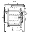
- FIG. 1 is a drawing illustrating a washing machine in accordance with an embodiment.
- a washing machine 1 includes a cabinet 10, a tub 20 disposed at an inside the cabinet 10, a drum 30 rotatably disposed at an inside the tub 20, and a motor 40 rotatably driving the drum 30.
- an inlet 11 is formed so that a laundry may be inserted into an inside the drum 30.
- the inlet 11 is open/closed by a door 12 installed at the front surface portion of the cabinet 10.
- a water supply pipe 50 is installed to supply washing water to the tub 20.
- One side of the water supply pipe 50 is connected to an outside water supply source (not shown), and the other side of the water supply pipe 50 is connected to a detergent supply apparatus 60.
- the detergent supply apparatus 60 is connected to the tub 20 through a connection pipe 55. The water being supplied through the water supply pipe 50 passes through the detergent supply apparatus 60, and then is supplied to an inside the tub 20 along with detergent.
- a drain pump 70 and a drain pipe 75 configured to discharge the water at an inside the tub 20 to an outside the cabinet 10.
- a plurality of penetration holes 31 is formed to circulate the washing water, and at the inner circumferential surface of the drum 30, a plurality of lifters 32 is installed so that the ascension and the descension of the laundry may take place when the drum 30 is rotated.
- the drum 30 is connected to the motor 40 through a driving shaft 80.
- the driving shaft 80 is configured to deliver the rotational force of the motor 40 to the drum 30.
- One end portion of the driving shaft 80 is connected to the drum 30, and the other end portion of the driving shaft 80 is extended to an outer side of a rear wall 21 of the tub 20.
- a bearing housing 82 is installed to rotatably support the driving shaft 80.
- the bearing housing 82 may be formed of aluminum alloy, and may be inserted into the rear wall 21 of the tub 20 when the tub 20 is injection-molded.
- bearings 84 are installed so that the driving shaft 80 may be smoothly rotated.
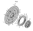
- FIG. 2 is a drawing illustrating a stator and a rotor of a motor in accordance with one embodiment of the present disclosure, the stator illustrated as being separated from the rotor.
- FIG. 3 is an enlarged view of 'B' portion of FIG. 2 .
- FIG. 4 is a drawing illustrating an appearance of the stator of FIG. 2 seen from a different angle.
- FIG. 5 is an enlarged view of 'C' portion of FIG. 4 .
- FIG. 6 is a cross-sectional view illustrating a coupling relationship between a tub and the stator.
- the motor in accordance with one embodiment of the present disclosure includes an inner-rotor type in which the rotor is disposed at an inner side of the stator, and an outer-rotor type in which the rotor is disposed at an outer side of the stator, and hereinafter, for the sake of convenience, the description will be provided based on the inner-rotor type motor.
- the motor 40 is coupled to an outer side of the tub 20, and rotates the drum 30 in both directions by providing driving force to the drum 30.
- the motor 40 includes a stator 100 mounted at the rear wall 21 of the tub 20, and a rotor 200 disposed around the stator 100 and configured to be rotated by electromagnetically interacting with the stator 100.
- the stator 100 includes a stator body 110 in a circular shape, which is formed by coupling a stator core 101 of metallic material with insulators 102a and 102b that cover the stator core 101 from an upper side and a lower side of the stator core 101 (refer to FIG. 8 ), a plurality of stator teeth 120 arranged in a circumferential direction of the stator body 110, a coil 130 wound around the plurality of stator teeth 110, a plurality of fixing ribs 140, a plurality of fixing pins 142, and a plurality of fixing holes 144 configured to fix the stator 100 to the rear wall 21 of the tub 20.
- the stator body 110 is configured to support the plurality of stator teeth 120.
- the plurality of stator teeth 120 is protruded in a radial structure in a direction facing a center of the stator body 110 from an inner circumferential surface of the stator body 110, and is arranged in a circumferential direction of the stator body 110 while being spaced apart from each other.
- the plurality of fixing ribs 140 are protrudedly formed in a predetermined length toward the rear wall 21 of the tub 20 from one side surface 110a of the stator body 110 facing the rear wall 21 of the tub 20, and are disposed while being spaced apart from each other by a predetermined distance in a circumferential direction of the stator body 110.
- the plurality of fixing pins 142 is protruded in a predetermined length toward the rear wall 21 of the tub 20 from one surface 140a of the plurality of fixing ribs 140 facing the rear wall 21 of the tub 20.
- the plurality of fixing pins 142 while being inserted into the rear wall 21 of the tub 20, is configured to determine the position of the stator 100 prior to fixing the stator 100 to the rear wall 21 of the tub 20.
- Each of the fixing hole 144 is concentrically disposed with each of the fixing pins 142, and is formed by penetrating through a center of the fixing pin 142, through a portion of the stator body 110 at which the center of the fixing pin 142 is positioned, and through the fixing rib 140.
- a fixing member 150 such as bolts is fixed to the rear wall 21 of the tub 20 through the fixing hole 144.
- the plurality of fixing ribs 140, the plurality of fixing pins 142, and the plurality of fixing holes 144 may be integrally formed with each other at the insulators 102a and 102b in the process of injection-molding the insulators 102a and 102b.
- the support rib 160 is protruded toward a rear direction from the rear wall 21 of the tub 20, and is formed at the rear wall 21 of the tub 20 at a position corresponding to the fixing rib 140 so as to make contact with the fixing ribs 140 while in a state that the stator 100 is mounted.
- the first accommodation hole 161 is configured to accommodate the fixing pin 142, so that the position of the stator 100 may be determined before the stator 100 is fixed to the rear wall 21 of the tub 20, while the second accommodation hole 162 is configured to accommodate the fixing member 150 such as a bolt, so that the stator 100 may be fixed to the rear wall 21 of the tub 20.
- the second accommodation hole 162 may be provided with a smaller diameter when compared to the first accommodation hole 161.
- the first accommodation hole 161 and the second accommodation hole 162 may be integrally formed with each other at the tub 20 in the process of injection-molding the tub 21.
- the fixing pin 142 and the fixing hole 144 are concentrically positioned with each other, when an injection mold of the insulators 102a and 102b forming the stator body 110is manufactured, a tool configured to process the fixing pin 142 and the fixing hole 144 may be able to simultaneously process the fixing pin 142 and the fixing hole 144 at one position, and thus the processing position error of the fixing pin 142 and the fixing hole 144 may be decreased.
- first accommodation hole 161 and the second accommodation hole 162 corresponding to the fixing pin 142 and the fixing hole 144, respectively, are concentrically positioned with each other, when an injection mold of the tub 20 is being manufactured, a tool configured to process the first accommodation hole 161 and the second accommodation hole 162 may be able to simultaneously process the first accommodation hole 161 and the second accommodation hole 162 at one position, and thus the processing position error of the first accommodation hole 161 and the second accommodation hole 162 may be decreased.
- the stator 100 is fixed to a constant position at the rear wall 21 of the tub 20 at all times, the concentricity error between the stator 100 and a rotor 200 is prevented, and the durability of the motor 40 is enhanced.
- FIG. 7 is an enlarged view of 'A' portion of FIG. 1 .
- the stator 100 includes at least one water penetrating prevention member 170 protruded from the stator body 110 to prevent water from being penetrated to the coil 130.
- the water penetrating prevention member 170 includes a first water penetrating prevention rib 171 protruded toward the rear wall 21 of the tub 20 from the one side surface 110a of the stator body 110 facing the rear wall 21 of the tub 20 in a state when the stator 100 is fixed to the rear wall 21 of the tub 20, and a second water penetrating prevention rib 172 protruded toward an opposite direction of the first water penetrating prevention rib 171 from the other end surface 110b that is opposite to the one side surface 110a of the stator body 110.
- the first water penetrating prevention rib 171 and the second water penetrating prevention rib 172 are each disposed in the circumferential direction of the stator 100, and are provided at an inner side in a radial direction of the stator 100 when compared to the fixing ribs 140.
- the length in which the first water penetrating prevention rib 171 is protruded is needed to be shorter than the length in which the fixing rib 140 is protruded. If the length in which the first water penetrating prevention member 171 is protruded is longer than the length in which the fixing rib 140 is protruded, in the process of mounting the stator 100, the first water penetration prevention rib 171 may make contact with the rear wall 21 of the tub 20 before the fixing rib 140 makes contact with the rear wall 21, and thus the fixing rib 140 may not make contact with the support rib 160.
- first water penetrating prevention rib 171 and the second water penetrating prevention rib 172 may be integrally formed with the insulators 102a and 102b in the process of injection-molding the insulator 102a and 102b.
- the water that is reached at an upper portion of the stator 100 by falling or being scattered from an upper portion of the tub 20 flows down toward a lower portion of the stator 100 along the surface of the first water penetrating prevention rib 171 or the second water penetrating prevention rib 172, and thus the penetration of the water into the coil 130 is prevented in advance.
- FIG. 8 is an exploded perspective view illustrating an exploded structure of the stator.
- the stator 100 includes the stator core 101 including a core body 101a having an inner circumferential surface and an outer circumferential surface, and a plurality of core teeth 101b protruded in a radial structure toward a direction facing a center of the core body 101a from the inner circumferential surface of the core body 101 a, and the upper and the lower insulators 102a and 102b covering an outer side of the stator core 101.
- the stator core 101 may be formed in a method of stacking press-processed metal sheets.
- the upper insulator 102a and the lower insulators 102b includes a plurality of penetration holes 144a and a plurality of penetrating holes 144b, respectively, the plurality of penetration holes 144a and the plurality of penetrating holes 144b forming the fixing holes 144 when the upper and the lower insulators 102a and 102b are coupled to each other, and the plurality of fixing ribs 140 and the plurality of fixing pins 142 are formed at one of the upper insulator 102a and the lower insulator 102b.
- the upper and the lower insulators 102a and 102b are formed of the material having electrical insulation characteristic, and a connector housing 180 into which a connector 310, which is configured to supply power to the coil 130 wound at the upper and the lower insulators 102a and 102b for current to flow, is inserted at one of the upper and the lower insulators 102a and 102b.
- the connector housing 180 is integrally injection-molded with one of the upper and the lower insulators 102a and 102b in the process of injection-molding the upper and the lower insulators 102a and 102b.
- Connection terminals 190 having metallic material that electrically connect the coil 130 to the connector 310 are inserted into the connector housing 180, and the connection terminals 190 may be inserted into the connector housing 180 in the process of injection-molding the upper and the lower insulators 102a and 102b.
- the connector housing 180 integrally injection-molded with one of the upper and the lower insulators 102a and 102b, the cost of separately manufacturing the connector housing 180 is decreased, and since the process of assembling the connector housing 180 to the stator 100 is omitted, the productivity is enhanced.
Landscapes
- Engineering & Computer Science (AREA)
- Textile Engineering (AREA)
- Power Engineering (AREA)
- Main Body Construction Of Washing Machines And Laundry Dryers (AREA)
- Motor Or Generator Frames (AREA)
- Insulation, Fastening Of Motor, Generator Windings (AREA)
- Iron Core Of Rotating Electric Machines (AREA)
Abstract
Description
- Embodiments relate to a motor configured to generate rotational force, and a washing machine having the same.
- A washing machine is an apparatus configured to wash clothes by use of power, and in general, includes a tub to store washing water, a drum rotatably installed at an inside the tub, and a motor configured to rotatably drive the drum.
- The motor is an apparatus configured to obtain rotational force from electric energy, and includes a stator and a rotor. The rotor is configured to electromagnetically interact with the stator, and is rotated by the force acting in between a magnetic field and the current that flows at coils.
- In general, the stator is fixed to a rear wall of the tub by use of a plurality of fixing pins and bolts. The fixing pins are configured to determine the position of the stator, and the bolts are configured to fix the stator, the position of which is determined by the fixing pin, to a rear wall of the tub.
- The stator is provided with fixing pins, separately formed from penetration holes into which the bolts are inserted. In the case as such, in processing the fixing pins and penetration holes, due to a processing error, the stator may not be able to be fixed at a right position, and thus a concentricity defect may be occurred between the stator and the rotor, thereby resulting in a decreased performance and a difference in the performance of the motor. In a case when the concentricity defect is severe, interference between the rotor and the stator may be occurred.
- In an aspect of one or more embodiments, there is provided a motor having an improved structure to be driven while maintaining a constant level of performance, and a washing machine having the same.
- In an aspect of one or more embodiments, there is provided a motor having an improved structure to prevent water from penetrating into an inner side of the motor, and a washing machine having the same.
- In an aspect of one or more embodiments, there is provided a motor having an improved structure to enhance productivity and assembly performance, and a washing machine having the same.
- In accordance with an aspect of one or more embodiments, there is provided a washing machine which includes a body, a tub, a drum, and a motor. The tub may be disposed inside the body The drum may be rotatably disposed inside the tub. The motor may be coupled to a rear surface of the tub to drive the drum. The motor may include a stator and a rotor. The stator may include at least one fixing pin inserted into the rear surface of the tub, and at least one fixing hole concentrically disposed with the at least one fixing pin. The rotor may be rotatably disposed at an inner side or at an outer side of the stator.
- The stator may include a stator body and at least one fixing rib. The stator body may have a circular-shape. The at least one fixing rib may be disposed in a circumferential direction of the stator body, and may protrude from one side surface of the stator body toward the rear surface of the tub. The at least one fixing pin may protrude from the at least one fixing rib toward the rear surface of the tub.
- The at least one fixing rib may include a plurality of fixing ribs separated from each other and disposed in the circumferential direction of the stator body, and may protrude from one side surface of the stator body toward the rear surface of the tub, and the at least one fixing pin may include a plurality of fixing pins and each fixing pin may protrude from each fixing rib toward the rear surface of the tub.
- The at least one fixing hole may be penetratively formed through a center of the at least one fixing pin, through a portion of the stator body at which the center of the at least one fixing pin is positioned, and through the at least one fixing rib.
- The tub may include at least one first accommodation hole and at least one second accommodation hole. The at least one first accommodation hole may allow the at least one fixing pin to be insertedly accommodated therein. The at least one second accommodation hole may be concentrically disposed with the at least one first accommodation hole, and configured to communicate with the at least one fixing hole in a state that the at least one fixing pin is insertedly accommodated in the at least one first accommodation hole.
- The washing machine may further include at least one fixing member configured to fix the stator to the rear surface of the tub. The at least one fixing member may be fixedly accommodated in the at least one second accommodation hole after passing through the at least one fixing hole.
- The tub may include a support rib protruded from the rear surface of the tub toward a rear side, and configured to support the stator by making contact with the at least one fixing rib when the stator is in a fixed state. The at least one first accommodation hole and the at least one second accommodation hole may be formed at the support rib.
- The stator may include a stator body having a circular-shape, a plurality of stator teeth, a coil and at least one water penetration prevention member. The plurality of stator teeth may be arranged in a circumferential direction of the stator body. The coil may be wound around the plurality of stator teeth. The at least one water penetration prevention member may be protruded from the stator body and configured to prevent water from penetrating into the coil.
- The at least one water penetration prevention member may include a first water penetration prevention rib and a second water penetration prevention rib. The first water penetration prevention rib may be protruded from one surface of the stator body that faces the rear surface of the tub toward the rear surface of the tub when the stator is fixed to the rear surface of the tub. The second water penetration prevention rib may be protruded from the other surface of the stator body opposite to the one surface of the stator body in an opposite direction to the first water penetration prevention rib when the stator is fixed to the rear surface of the tub.
- The at least one water penetration prevention member may be disposed in the circumferential direction of the stator body.
- The stator includes a stator body having a circular-shape, a plurality of stator teeth, a coil and a connector housing. The plurality of stator teeth may be arranged in a circumferential direction of the stator body. The coil may be wound around the plurality of stator teeth. The connector housing may be integrally formed with the stator body and into which a connector configured to supply power to the coil is inserted.
- In accordance with an aspect of one or more embodiments, there is provided a washing machine includes a body, a tub, a drum, and a motor. The tub may be disposed inside the body. The drum may be rotatably disposed inside the tub. The motor may be coupled to a rear surface of the tub to drive the drum. The motor may include a stator and a rotor. The stator may include a stator body having a circular-shape, a plurality of stator teeth, a coil and at least one water penetration prevention member. The plurality of stator teeth may be arranged in a circumferential direction of the stator body. The coil may be wound around the plurality of stator teeth. The at least one water penetration prevention member may be protruded from the stator body and configured to prevent water from penetrating into the coil. The rotor may be rotatably disposed at an inner side of the stator.
- The at least one water penetration prevention member may include a first water penetration prevention rib and a second water penetration prevention rib. The first water penetration prevention rib may be protruded from one surface of the stator body that faces the rear surface of the tub toward the rear surface of the tub when the stator is fixed to the rear surface of the tub. The second water penetration prevention rib may be protruded from the other surface of the stator body opposite to the one surface of the stator body in an opposite direction of the first water penetration prevention rib when the stator is fixed to the rear surface of the tub.
- The at least one water penetration prevention member may be disposed in the circumferential direction of the stator body.
- The washing machine may further include at least one fixing rib protruded from one side surface of the stator body toward the rear surface of the tub. The fixing rib may be disposed at an outer side of the first water penetration prevention rib in a radial direction of the stator body.
- In accordance with an aspect one or more embodiments, there is provided a washing machine includes a body, a tub, a drum, and a motor. The tub may be disposed inside the body. The drum may be rotatably disposed inside the tub. The motor may be configured to drive the drum. The motor may include a stator and a rotor. The stator may include a stator core, an insulator, a coil and a connector housing. The insulator may cover the stator core. The coil may be wound around the insulator. The connector housing may be integrally formed with the insulator and into which a connector configured to supply power to the coil is inserted. The rotor may be rotatably disposed at an inner side or at an outer side of the stator.
- The insulator may include an upper insulator and a lower insulator that are configured to cover the stator core from an upper side and a lower side thereof, respectively. The connector housing may be integrally formed with one of the upper insulator and the lower insulator.
- The washing machine may further include connection terminals formed of metal configured to electrically connect the coil to the connector. The connection terminals may be inserted into the insulator.
- As described above, a fixing pin configured to determine the position of a stator is concentrically disposed with a fixing hole, into which a fixing member configured to fix the stator, so that the stator is fixed to a determined position at all times, and thereby the concentricity defect between the stator and a rotor is prevented.
- Since the water that falls from an upper portion of a tub is guided to an outer side of coils along a water penetration prevention rib formed at a stator, a short circuit caused by the penetration of water is prevented.
- Since a connector housing, into which a connector configured to supply power to coils is inserted, is integrally formed with a stator, the cost of separately molding the connector housing is saved, and the process of assembling the separately-molded connector housing to the stator is omitted, and thereby the productivity and assembly performance are enhanced.
- In addition, the durability of a motor is enhanced.
- These and/or other aspects of the disclosure will become apparent and more readily appreciated from the following description o embodiments, taken in conjunction with the accompanying drawings of which:
-
FIG. 1 is a drawing illustrating a washing machine in accordance with an embodiment; -
FIG. 2 is a drawing illustrating a stator and a rotor of a motor in accordance with one embodiment of the present disclosure, the stator illustrated as being separated from the rotor; -
FIG. 3 is an enlarged view of 'B' portion ofFIG. 2 ; -
FIG. 4 is a drawing illustrating an appearance of the stator ofFIG. 2 seen from a different angle; -
FIG. 5 is an enlarged view of 'C' portion ofFIG. 4 ; -
FIG. 6 is a cross-sectional view illustrating a coupling relationship between a tub and the stator; -
FIG. 7 is an enlarged view of 'A' portion ofFIG. 1 ; and -
FIG. 8 is an exploded perspective view illustrating an exploded structure of the stator. - Reference will now be made in detail to embodiments of the present disclosure, examples of which are illustrated in the accompanying drawings, wherein like reference numerals refer to like elements throughout.
-
FIG. 1 is a drawing illustrating a washing machine in accordance with an embodiment. - As illustrated on
FIG. 1 , awashing machine 1 includes acabinet 10, atub 20 disposed at an inside thecabinet 10, adrum 30 rotatably disposed at an inside thetub 20, and a motor 40 rotatably driving thedrum 30. - At a front surface portion of the
cabinet 10, aninlet 11 is formed so that a laundry may be inserted into an inside thedrum 30. Theinlet 11 is open/closed by adoor 12 installed at the front surface portion of thecabinet 10. - At an upper portion of the
tub 20, awater supply pipe 50 is installed to supply washing water to thetub 20. One side of thewater supply pipe 50 is connected to an outside water supply source (not shown), and the other side of thewater supply pipe 50 is connected to adetergent supply apparatus 60. Thedetergent supply apparatus 60 is connected to thetub 20 through aconnection pipe 55. The water being supplied through thewater supply pipe 50 passes through thedetergent supply apparatus 60, and then is supplied to an inside thetub 20 along with detergent. - At a lower portion of the
tub 20, adrain pump 70 and adrain pipe 75 configured to discharge the water at an inside thetub 20 to an outside thecabinet 10. - At the circumference of the
drum 30, a plurality of penetration holes 31 is formed to circulate the washing water, and at the inner circumferential surface of thedrum 30, a plurality oflifters 32 is installed so that the ascension and the descension of the laundry may take place when thedrum 30 is rotated. - The
drum 30 is connected to the motor 40 through a drivingshaft 80. The drivingshaft 80 is configured to deliver the rotational force of the motor 40 to thedrum 30. One end portion of the drivingshaft 80 is connected to thedrum 30, and the other end portion of the drivingshaft 80 is extended to an outer side of arear wall 21 of thetub 20. - At the
rear wall 21 of thetub 20, a bearinghousing 82 is installed to rotatably support the drivingshaft 80. The bearinghousing 82 may be formed of aluminum alloy, and may be inserted into therear wall 21 of thetub 20 when thetub 20 is injection-molded. In between the bearinghousing 82 and the drivingshaft 80,bearings 84 are installed so that the drivingshaft 80 may be smoothly rotated. - Hereinafter, a structure and a principle of the motor 40 being mounted at the
rear wall 21 of thetub 20 will be described in detail. -
FIG. 2 is a drawing illustrating a stator and a rotor of a motor in accordance with one embodiment of the present disclosure, the stator illustrated as being separated from the rotor.FIG. 3 is an enlarged view of 'B' portion ofFIG. 2 .FIG. 4 is a drawing illustrating an appearance of the stator ofFIG. 2 seen from a different angle.FIG. 5 is an enlarged view of 'C' portion ofFIG. 4 .FIG. 6 is a cross-sectional view illustrating a coupling relationship between a tub and the stator. The motor in accordance with one embodiment of the present disclosure includes an inner-rotor type in which the rotor is disposed at an inner side of the stator, and an outer-rotor type in which the rotor is disposed at an outer side of the stator, and hereinafter, for the sake of convenience, the description will be provided based on the inner-rotor type motor. - As illustrated on
FIGS. 1 to 6 , the motor 40 is coupled to an outer side of thetub 20, and rotates thedrum 30 in both directions by providing driving force to thedrum 30. The motor 40 includes astator 100 mounted at therear wall 21 of thetub 20, and arotor 200 disposed around thestator 100 and configured to be rotated by electromagnetically interacting with thestator 100. - The
stator 100 includes astator body 110 in a circular shape, which is formed by coupling astator core 101 of metallic material withinsulators stator core 101 from an upper side and a lower side of the stator core 101 (refer toFIG. 8 ), a plurality ofstator teeth 120 arranged in a circumferential direction of thestator body 110, acoil 130 wound around the plurality ofstator teeth 110, a plurality of fixingribs 140, a plurality of fixingpins 142, and a plurality of fixingholes 144 configured to fix thestator 100 to therear wall 21 of thetub 20. - The
stator body 110 is configured to support the plurality ofstator teeth 120. The plurality ofstator teeth 120 is protruded in a radial structure in a direction facing a center of thestator body 110 from an inner circumferential surface of thestator body 110, and is arranged in a circumferential direction of thestator body 110 while being spaced apart from each other. - The plurality of fixing
ribs 140 are protrudedly formed in a predetermined length toward therear wall 21 of thetub 20 from oneside surface 110a of thestator body 110 facing therear wall 21 of thetub 20, and are disposed while being spaced apart from each other by a predetermined distance in a circumferential direction of thestator body 110. - The plurality of fixing
pins 142 is protruded in a predetermined length toward therear wall 21 of thetub 20 from onesurface 140a of the plurality of fixingribs 140 facing therear wall 21 of thetub 20. The plurality of fixingpins 142, while being inserted into therear wall 21 of thetub 20, is configured to determine the position of thestator 100 prior to fixing thestator 100 to therear wall 21 of thetub 20. - Each of the fixing
hole 144 is concentrically disposed with each of the fixing pins 142, and is formed by penetrating through a center of the fixingpin 142, through a portion of thestator body 110 at which the center of the fixingpin 142 is positioned, and through the fixingrib 140. A fixingmember 150 such as bolts is fixed to therear wall 21 of thetub 20 through the fixinghole 144. - The plurality of fixing
ribs 140, the plurality of fixingpins 142, and the plurality of fixingholes 144 may be integrally formed with each other at theinsulators insulators - A support rib 160configured to support the
stator 100 by making contact with the fixingrib 140 while in a state that thestator 100 is mounted at therear wall 21 of thetub 20, afirst accommodation holes 161 through which thefixing pin 142 is insertedly accommodated, and asecond accommodation hole 162 concentrically disposed with thefirst accommodation hole 161 are provided at therear wall 21 of thetub 20 at which thestator 100 is mounted. - The
support rib 160 is protruded toward a rear direction from therear wall 21 of thetub 20, and is formed at therear wall 21 of thetub 20 at a position corresponding to the fixingrib 140 so as to make contact with the fixingribs 140 while in a state that thestator 100 is mounted. - The
first accommodation hole 161 is configured to accommodate the fixingpin 142, so that the position of thestator 100 may be determined before thestator 100 is fixed to therear wall 21 of thetub 20, while thesecond accommodation hole 162 is configured to accommodate the fixingmember 150 such as a bolt, so that thestator 100 may be fixed to therear wall 21 of thetub 20. Thesecond accommodation hole 162 may be provided with a smaller diameter when compared to thefirst accommodation hole 161. - The
first accommodation hole 161 and thesecond accommodation hole 162 may be integrally formed with each other at thetub 20 in the process of injection-molding thetub 21. - As the above, since the fixing
pin 142 and the fixinghole 144 are concentrically positioned with each other, when an injection mold of theinsulators pin 142 and the fixinghole 144 may be able to simultaneously process the fixingpin 142 and the fixinghole 144 at one position, and thus the processing position error of the fixingpin 142 and the fixinghole 144 may be decreased. In the same manner, since thefirst accommodation hole 161 and thesecond accommodation hole 162 corresponding to the fixingpin 142 and the fixinghole 144, respectively, are concentrically positioned with each other, when an injection mold of thetub 20 is being manufactured, a tool configured to process thefirst accommodation hole 161 and thesecond accommodation hole 162 may be able to simultaneously process thefirst accommodation hole 161 and thesecond accommodation hole 162 at one position, and thus the processing position error of thefirst accommodation hole 161 and thesecond accommodation hole 162 may be decreased. Thus, since thestator 100 is fixed to a constant position at therear wall 21 of thetub 20 at all times, the concentricity error between thestator 100 and arotor 200 is prevented, and the durability of the motor 40 is enhanced. - Hereinafter, a structure of preventing a phenomenon in which water is penetrated into the
coils 130 in a state when thestator 100 is mounted at therear wall 21 of thetub 20 will be described. -
FIG. 7 is an enlarged view of 'A' portion ofFIG. 1 . - As illustrated on
FIG. 1 ,FIG. 2 ,FIG. 4 , andFIG. 7 , thestator 100 includes at least one water penetratingprevention member 170 protruded from thestator body 110 to prevent water from being penetrated to thecoil 130. - The water penetrating
prevention member 170 includes a first water penetratingprevention rib 171 protruded toward therear wall 21 of thetub 20 from the oneside surface 110a of thestator body 110 facing therear wall 21 of thetub 20 in a state when thestator 100 is fixed to therear wall 21 of thetub 20, and a second water penetratingprevention rib 172 protruded toward an opposite direction of the first water penetratingprevention rib 171 from theother end surface 110b that is opposite to the oneside surface 110a of thestator body 110. - The first water penetrating
prevention rib 171 and the second water penetratingprevention rib 172 are each disposed in the circumferential direction of thestator 100, and are provided at an inner side in a radial direction of thestator 100 when compared to the fixingribs 140. - The length in which the first water penetrating
prevention rib 171 is protruded is needed to be shorter than the length in which the fixingrib 140 is protruded. If the length in which the first water penetratingprevention member 171 is protruded is longer than the length in which the fixingrib 140 is protruded, in the process of mounting thestator 100, the first waterpenetration prevention rib 171 may make contact with therear wall 21 of thetub 20 before the fixingrib 140 makes contact with therear wall 21, and thus the fixingrib 140 may not make contact with thesupport rib 160. - In addition, the first water penetrating
prevention rib 171 and the second water penetratingprevention rib 172 may be integrally formed with theinsulators insulator - In a washing process, the water that is reached at an upper portion of the
stator 100 by falling or being scattered from an upper portion of thetub 20 flows down toward a lower portion of thestator 100 along the surface of the first water penetratingprevention rib 171 or the second water penetratingprevention rib 172, and thus the penetration of the water into thecoil 130 is prevented in advance. -
FIG. 8 is an exploded perspective view illustrating an exploded structure of the stator. - As illustrated on
FIG. 2 ,FIG. 4 , andFIG. 8 , thestator 100 includes thestator core 101 including acore body 101a having an inner circumferential surface and an outer circumferential surface, and a plurality ofcore teeth 101b protruded in a radial structure toward a direction facing a center of thecore body 101a from the inner circumferential surface of thecore body 101 a, and the upper and thelower insulators stator core 101. Thestator core 101 may be formed in a method of stacking press-processed metal sheets. - The
upper insulator 102a and thelower insulators 102b includes a plurality ofpenetration holes 144a and a plurality of penetratingholes 144b, respectively, the plurality ofpenetration holes 144a and the plurality of penetratingholes 144b forming the fixingholes 144 when the upper and thelower insulators ribs 140 and the plurality of fixingpins 142 are formed at one of theupper insulator 102a and thelower insulator 102b. - In addition, the upper and the
lower insulators connector housing 180 into which aconnector 310, which is configured to supply power to thecoil 130 wound at the upper and thelower insulators lower insulators lower insulators lower insulators -
Connection terminals 190 having metallic material that electrically connect thecoil 130 to theconnector 310 are inserted into theconnector housing 180, and theconnection terminals 190 may be inserted into theconnector housing 180 in the process of injection-molding the upper and thelower insulators - As the above, by having the
connector housing 180 integrally injection-molded with one of the upper and thelower insulators connector housing 180 is decreased, and since the process of assembling theconnector housing 180 to thestator 100 is omitted, the productivity is enhanced. - Although a few embodiments of the present disclosure have been shown and described, it would be appreciated by those skilled in the art that changes may be made in these embodiments without departing from the principles and spirit of the disclosure, the scope of which is defined in the claims and their equivalents.
Claims (13)
- A washing machine, comprising:a body;a tub disposed inside the body;a drum rotatably disposed inside the tub; anda motor coupled to a rear surface of the tub to drive the drum,wherein the motor comprises:a stator comprising at least one fixing pin inserted into the rear surface of the tub and at least one fixing hole concentrically disposed with the at least one fixing pin; anda rotor rotatably disposed at an inner side or at an outer side of the stator.
- The washing machine of claim 1, wherein the stator comprises:a stator body having a circular-shape; andat least one fixing rib disposed in a circumferential direction of the stator body, and protruded from one side surface of the stator body toward the rear surface of the tub,wherein the at least one fixing pin protrudes from the at least one fixing rib toward the rear surface of the tub.
- The washing machine of claim 2, wherein the at least one fixing hole is formed by penetrating through a center of the at least one fixing pin, through a portion of the stator body at which the center of the at least one fixing pin is positioned, and through the at least one fixing rib.
- The washing machine of claim 3, wherein the tub comprises:at least one first accommodation hole in which the fixing pin is insertedly accommodated; andat least one second accommodation hole concentrically disposed with at least one first accommodation hole, and configured to communicate with the at least one fixing hole in a state that the at least one fixing pin is insertedly accommodated in the at least one first accommodation hole.
- The washing machine of claim 4, further comprising:at least one fixing member configured to fix the stator to the rear surface of the tub,wherein the at least one fixing member is fixedly accommodated in the second accommodation hole after passing through the at least one fixing hole.
- The washing machine of claim 5, wherein the tub comprises a support rib protruded from the rear surface of the tub toward a rear side, and configured to support the stator by making contact with the at least one fixing rib when the stator is in a fixed state,
wherein the at least one first accommodation hole and the at least one second accommodation hole are formed at the support rib. - The washing machine of claim 1, wherein the stator comprises:a stator body having a circular-shape;a plurality of stator teeth arranged in a circumferential direction of the stator body;a coil wound around the plurality of stator teeth; andat least one water penetration prevention member protruded from the stator body and configured to prevent water from penetrating into the coil.
- The washing machine of claim 7, wherein the at least one water penetration prevention member comprises:a first water penetration prevention rib protruded from one surface of the stator body that faces the rear surface of the tub toward the rear surface of the tub when the stator is fixed to the rear surface of the tub; anda second water penetration prevention rib protruded from the other surface of the stator body opposite to the one surface of the stator body in an opposite direction to the first water penetration prevention rib when the stator is fixed to the rear surface of the tub.
- The washing machine of claim 7, wherein the at least one water penetration prevention member is disposed in the circumferential direction of the stator body.
- The washing machine of claim 1, wherein the stator comprises:a stator body having a circular-shape;a plurality of stator teeth arranged in a circumferential direction of the stator body;a coil wound around the plurality of stator teeth; anda connector housing integrally formed with the stator body and into which a connector configured to supply power to the coil is inserted.
- The washing machine of claim 1, wherein the stator comprises:a stator core;an insulator covering the stator core;a coil wound around the insulator; anda connector housing integrally formed with the insulator and into which a connector configured to supply power to the coil is inserted.
- The washing machine of claim 11, wherein:the insulator comprises an upper insulator and a lower insulator that are configured to cover the stator core from an upper side and a lower side thereof, respectively, andthe connector housing is integrally formed with one of the upper insulator and the lower insulator.
- The washing machine of claim 12, further comprising connection terminals formed of metal configured to electrically connect the coil to the connector,
wherein the connection terminals are inserted into the insulator.
Applications Claiming Priority (1)
| Application Number | Priority Date | Filing Date | Title |
|---|---|---|---|
| KR1020120012212A KR20130091019A (en) | 2012-02-07 | 2012-02-07 | Motor and washing machine having the same |
Publications (2)
| Publication Number | Publication Date |
|---|---|
| EP2626459A1 true EP2626459A1 (en) | 2013-08-14 |
| EP2626459B1 EP2626459B1 (en) | 2019-10-16 |
Family
ID=47715879
Family Applications (1)
| Application Number | Title | Priority Date | Filing Date |
|---|---|---|---|
| EP13153943.9A Active EP2626459B1 (en) | 2012-02-07 | 2013-02-05 | Motor and washing machine having the same |
Country Status (4)
| Country | Link |
|---|---|
| US (1) | US20130200747A1 (en) |
| EP (1) | EP2626459B1 (en) |
| KR (1) | KR20130091019A (en) |
| CN (1) | CN103243521B (en) |
Cited By (1)
| Publication number | Priority date | Publication date | Assignee | Title |
|---|---|---|---|---|
| EP3067457A1 (en) | 2015-03-12 | 2016-09-14 | Whirlpool Corporation | Washing machine with direct drive motor and method for its manufacturing |
Families Citing this family (6)
| Publication number | Priority date | Publication date | Assignee | Title |
|---|---|---|---|---|
| CN104832546B (en) * | 2014-02-12 | 2019-03-29 | 青岛海尔滚筒洗衣机有限公司 | A kind of bearing support block and the washing machine with it |
| CN110857502A (en) * | 2018-08-10 | 2020-03-03 | 广东威灵电机制造有限公司 | Motor assembly and washing machine |
| CN111534975B (en) * | 2020-05-09 | 2022-08-02 | 无锡小天鹅电器有限公司 | Stator, motor and clothes treatment equipment |
| KR102576782B1 (en) * | 2021-11-11 | 2023-09-11 | 뉴모텍(주) | Motor for Washing Machine |
| CN117411202B (en) * | 2023-10-13 | 2024-05-28 | 合肥梅洛尼智能科技有限公司 | Integrated structure of drum washing machine outer drum and direct drive motor stator |
| WO2026088730A1 (en) * | 2024-10-24 | 2026-04-30 | カヤバ株式会社 | Stator securing structure and electric pump |
Citations (5)
| Publication number | Priority date | Publication date | Assignee | Title |
|---|---|---|---|---|
| EP1550758A2 (en) * | 2003-12-30 | 2005-07-06 | Lg Electronics Inc. | Driving unit of top loading drum type washing machine |
| EP1580311A1 (en) * | 2004-03-24 | 2005-09-28 | Diehl AKO Stiftung & Co. KG | Direct drive motor and assembly method |
| WO2006083083A2 (en) * | 2005-02-01 | 2006-08-10 | Lg Electronics Inc. | Driving apparatus for washing machine |
| WO2008010674A2 (en) * | 2006-07-20 | 2008-01-24 | Lg Electronics Inc. | Drum type laundry machine |
| EP2202342A1 (en) * | 2008-12-23 | 2010-06-30 | Amotech Co., Ltd. | Slimtype stator having integrated cover structure, slim type motor and direct drive apparatus for drum-washing machine including the same |
Family Cites Families (9)
| Publication number | Priority date | Publication date | Assignee | Title |
|---|---|---|---|---|
| GB622908A (en) * | 1945-02-17 | 1949-05-10 | Gen Motors Corp | Improved clothes washing machine |
| DE1610254A1 (en) * | 1965-05-06 | 1970-10-29 | Texas Instruments Inc | Washing machine |
| NZ247033A (en) * | 1988-09-28 | 1994-10-26 | Fisher & Paykel | Drive for spin washer: agitator shaft bearings are motor rotor bearings |
| KR100777273B1 (en) * | 2001-06-12 | 2007-11-20 | 엘지전자 주식회사 | Fully automatic washing machine |
| KR100564442B1 (en) * | 2003-12-10 | 2006-03-29 | 엘지전자 주식회사 | Top Loading Drum Washing Machine |
| KR100651850B1 (en) * | 2005-02-01 | 2006-12-01 | 엘지전자 주식회사 | washer |
| WO2008027535A2 (en) * | 2006-09-01 | 2008-03-06 | Sears David B | Insulator for stator assembly of brushless dc motor |
| KR20100090482A (en) * | 2009-02-06 | 2010-08-16 | 삼성전자주식회사 | Motor and washing machine having the same |
| US8405268B2 (en) * | 2010-02-18 | 2013-03-26 | Nidec Motor Corporation | Stator with monolithic mounting bosses and assembly comprising the same |
-
2012
- 2012-02-07 KR KR1020120012212A patent/KR20130091019A/en not_active Withdrawn
-
2013
- 2013-01-30 US US13/754,148 patent/US20130200747A1/en not_active Abandoned
- 2013-02-05 EP EP13153943.9A patent/EP2626459B1/en active Active
- 2013-02-06 CN CN201310047424.9A patent/CN103243521B/en active Active
Patent Citations (5)
| Publication number | Priority date | Publication date | Assignee | Title |
|---|---|---|---|---|
| EP1550758A2 (en) * | 2003-12-30 | 2005-07-06 | Lg Electronics Inc. | Driving unit of top loading drum type washing machine |
| EP1580311A1 (en) * | 2004-03-24 | 2005-09-28 | Diehl AKO Stiftung & Co. KG | Direct drive motor and assembly method |
| WO2006083083A2 (en) * | 2005-02-01 | 2006-08-10 | Lg Electronics Inc. | Driving apparatus for washing machine |
| WO2008010674A2 (en) * | 2006-07-20 | 2008-01-24 | Lg Electronics Inc. | Drum type laundry machine |
| EP2202342A1 (en) * | 2008-12-23 | 2010-06-30 | Amotech Co., Ltd. | Slimtype stator having integrated cover structure, slim type motor and direct drive apparatus for drum-washing machine including the same |
Cited By (1)
| Publication number | Priority date | Publication date | Assignee | Title |
|---|---|---|---|---|
| EP3067457A1 (en) | 2015-03-12 | 2016-09-14 | Whirlpool Corporation | Washing machine with direct drive motor and method for its manufacturing |
Also Published As
| Publication number | Publication date |
|---|---|
| US20130200747A1 (en) | 2013-08-08 |
| CN103243521B (en) | 2016-12-28 |
| KR20130091019A (en) | 2013-08-16 |
| CN103243521A (en) | 2013-08-14 |
| EP2626459B1 (en) | 2019-10-16 |
Similar Documents
| Publication | Publication Date | Title |
|---|---|---|
| EP2626459B1 (en) | Motor and washing machine having the same | |
| US8220295B2 (en) | Driving apparatus for washing machine | |
| KR102149776B1 (en) | Motor and washing machine having the same | |
| EP2375544B1 (en) | Motor for washing machine and washing machine having the same | |
| US20080122300A1 (en) | Motor | |
| CN103248144B (en) | Motor and there is the washing machine of this motor | |
| JP2008206737A (en) | Washing machine | |
| US9431866B2 (en) | Motor and washing machine having the same | |
| US9331537B2 (en) | Motor and washing machine having the same | |
| KR101940516B1 (en) | Motor and washing machine having the same | |
| CN107786043B (en) | Motor and its stator | |
| KR101055129B1 (en) | Motor and clothing treatment device having same | |
| US12546050B2 (en) | Motor fixing structure and washing machine including the same | |
| KR20140041996A (en) | washer | |
| KR100582298B1 (en) | Motor mounting structure of washing machine and rotor structure of washing machine motor | |
| KR20150090791A (en) | Motor and refrigerator having the same | |
| KR20050066538A (en) | Motor mounting structure in washing machine | |
| KR20140036359A (en) | Washing machine |
Legal Events
| Date | Code | Title | Description |
|---|---|---|---|
| PUAI | Public reference made under article 153(3) epc to a published international application that has entered the european phase |
Free format text: ORIGINAL CODE: 0009012 |
|
| AK | Designated contracting states |
Kind code of ref document: A1 Designated state(s): AL AT BE BG CH CY CZ DE DK EE ES FI FR GB GR HR HU IE IS IT LI LT LU LV MC MK MT NL NO PL PT RO RS SE SI SK SM TR |
|
| AX | Request for extension of the european patent |
Extension state: BA ME |
|
| 17P | Request for examination filed |
Effective date: 20140214 |
|
| RBV | Designated contracting states (corrected) |
Designated state(s): AL AT BE BG CH CY CZ DE DK EE ES FI FR GB GR HR HU IE IS IT LI LT LU LV MC MK MT NL NO PL PT RO RS SE SI SK SM TR |
|
| STAA | Information on the status of an ep patent application or granted ep patent |
Free format text: STATUS: EXAMINATION IS IN PROGRESS |
|
| 17Q | First examination report despatched |
Effective date: 20181130 |
|
| RIC1 | Information provided on ipc code assigned before grant |
Ipc: D06F 37/30 20060101ALI20190401BHEP Ipc: D06F 37/20 20060101AFI20190401BHEP Ipc: H02K 1/12 20060101ALI20190401BHEP |
|
| GRAP | Despatch of communication of intention to grant a patent |
Free format text: ORIGINAL CODE: EPIDOSNIGR1 |
|
| STAA | Information on the status of an ep patent application or granted ep patent |
Free format text: STATUS: GRANT OF PATENT IS INTENDED |
|
| INTG | Intention to grant announced |
Effective date: 20190516 |
|
| GRAS | Grant fee paid |
Free format text: ORIGINAL CODE: EPIDOSNIGR3 |
|
| GRAA | (expected) grant |
Free format text: ORIGINAL CODE: 0009210 |
|
| STAA | Information on the status of an ep patent application or granted ep patent |
Free format text: STATUS: THE PATENT HAS BEEN GRANTED |
|
| AK | Designated contracting states |
Kind code of ref document: B1 Designated state(s): AL AT BE BG CH CY CZ DE DK EE ES FI FR GB GR HR HU IE IS IT LI LT LU LV MC MK MT NL NO PL PT RO RS SE SI SK SM TR |
|
| REG | Reference to a national code |
Ref country code: GB Ref legal event code: FG4D |
|
| REG | Reference to a national code |
Ref country code: CH Ref legal event code: EP |
|
| REG | Reference to a national code |
Ref country code: DE Ref legal event code: R096 Ref document number: 602013061696 Country of ref document: DE |
|
| REG | Reference to a national code |
Ref country code: IE Ref legal event code: FG4D |
|
| REG | Reference to a national code |
Ref country code: AT Ref legal event code: REF Ref document number: 1191353 Country of ref document: AT Kind code of ref document: T Effective date: 20191115 |
|
| REG | Reference to a national code |
Ref country code: NL Ref legal event code: MP Effective date: 20191016 |
|
| REG | Reference to a national code |
Ref country code: LT Ref legal event code: MG4D |
|
| REG | Reference to a national code |
Ref country code: AT Ref legal event code: MK05 Ref document number: 1191353 Country of ref document: AT Kind code of ref document: T Effective date: 20191016 |
|
| PG25 | Lapsed in a contracting state [announced via postgrant information from national office to epo] |
Ref country code: ES Free format text: LAPSE BECAUSE OF FAILURE TO SUBMIT A TRANSLATION OF THE DESCRIPTION OR TO PAY THE FEE WITHIN THE PRESCRIBED TIME-LIMIT Effective date: 20191016 Ref country code: LT Free format text: LAPSE BECAUSE OF FAILURE TO SUBMIT A TRANSLATION OF THE DESCRIPTION OR TO PAY THE FEE WITHIN THE PRESCRIBED TIME-LIMIT Effective date: 20191016 Ref country code: NL Free format text: LAPSE BECAUSE OF FAILURE TO SUBMIT A TRANSLATION OF THE DESCRIPTION OR TO PAY THE FEE WITHIN THE PRESCRIBED TIME-LIMIT Effective date: 20191016 Ref country code: PL Free format text: LAPSE BECAUSE OF FAILURE TO SUBMIT A TRANSLATION OF THE DESCRIPTION OR TO PAY THE FEE WITHIN THE PRESCRIBED TIME-LIMIT Effective date: 20191016 Ref country code: SE Free format text: LAPSE BECAUSE OF FAILURE TO SUBMIT A TRANSLATION OF THE DESCRIPTION OR TO PAY THE FEE WITHIN THE PRESCRIBED TIME-LIMIT Effective date: 20191016 Ref country code: LV Free format text: LAPSE BECAUSE OF FAILURE TO SUBMIT A TRANSLATION OF THE DESCRIPTION OR TO PAY THE FEE WITHIN THE PRESCRIBED TIME-LIMIT Effective date: 20191016 Ref country code: GR Free format text: LAPSE BECAUSE OF FAILURE TO SUBMIT A TRANSLATION OF THE DESCRIPTION OR TO PAY THE FEE WITHIN THE PRESCRIBED TIME-LIMIT Effective date: 20200117 Ref country code: AT Free format text: LAPSE BECAUSE OF FAILURE TO SUBMIT A TRANSLATION OF THE DESCRIPTION OR TO PAY THE FEE WITHIN THE PRESCRIBED TIME-LIMIT Effective date: 20191016 Ref country code: NO Free format text: LAPSE BECAUSE OF FAILURE TO SUBMIT A TRANSLATION OF THE DESCRIPTION OR TO PAY THE FEE WITHIN THE PRESCRIBED TIME-LIMIT Effective date: 20200116 Ref country code: PT Free format text: LAPSE BECAUSE OF FAILURE TO SUBMIT A TRANSLATION OF THE DESCRIPTION OR TO PAY THE FEE WITHIN THE PRESCRIBED TIME-LIMIT Effective date: 20200217 Ref country code: FI Free format text: LAPSE BECAUSE OF FAILURE TO SUBMIT A TRANSLATION OF THE DESCRIPTION OR TO PAY THE FEE WITHIN THE PRESCRIBED TIME-LIMIT Effective date: 20191016 Ref country code: BG Free format text: LAPSE BECAUSE OF FAILURE TO SUBMIT A TRANSLATION OF THE DESCRIPTION OR TO PAY THE FEE WITHIN THE PRESCRIBED TIME-LIMIT Effective date: 20200116 |
|
| PG25 | Lapsed in a contracting state [announced via postgrant information from national office to epo] |
Ref country code: RS Free format text: LAPSE BECAUSE OF FAILURE TO SUBMIT A TRANSLATION OF THE DESCRIPTION OR TO PAY THE FEE WITHIN THE PRESCRIBED TIME-LIMIT Effective date: 20191016 Ref country code: IS Free format text: LAPSE BECAUSE OF FAILURE TO SUBMIT A TRANSLATION OF THE DESCRIPTION OR TO PAY THE FEE WITHIN THE PRESCRIBED TIME-LIMIT Effective date: 20200224 Ref country code: HR Free format text: LAPSE BECAUSE OF FAILURE TO SUBMIT A TRANSLATION OF THE DESCRIPTION OR TO PAY THE FEE WITHIN THE PRESCRIBED TIME-LIMIT Effective date: 20191016 |
|
| PG25 | Lapsed in a contracting state [announced via postgrant information from national office to epo] |
Ref country code: AL Free format text: LAPSE BECAUSE OF FAILURE TO SUBMIT A TRANSLATION OF THE DESCRIPTION OR TO PAY THE FEE WITHIN THE PRESCRIBED TIME-LIMIT Effective date: 20191016 |
|
| REG | Reference to a national code |
Ref country code: DE Ref legal event code: R097 Ref document number: 602013061696 Country of ref document: DE |
|
| PG2D | Information on lapse in contracting state deleted |
Ref country code: IS |
|
| PG25 | Lapsed in a contracting state [announced via postgrant information from national office to epo] |
Ref country code: EE Free format text: LAPSE BECAUSE OF FAILURE TO SUBMIT A TRANSLATION OF THE DESCRIPTION OR TO PAY THE FEE WITHIN THE PRESCRIBED TIME-LIMIT Effective date: 20191016 Ref country code: DK Free format text: LAPSE BECAUSE OF FAILURE TO SUBMIT A TRANSLATION OF THE DESCRIPTION OR TO PAY THE FEE WITHIN THE PRESCRIBED TIME-LIMIT Effective date: 20191016 Ref country code: CZ Free format text: LAPSE BECAUSE OF FAILURE TO SUBMIT A TRANSLATION OF THE DESCRIPTION OR TO PAY THE FEE WITHIN THE PRESCRIBED TIME-LIMIT Effective date: 20191016 Ref country code: RO Free format text: LAPSE BECAUSE OF FAILURE TO SUBMIT A TRANSLATION OF THE DESCRIPTION OR TO PAY THE FEE WITHIN THE PRESCRIBED TIME-LIMIT Effective date: 20191016 Ref country code: IS Free format text: LAPSE BECAUSE OF FAILURE TO SUBMIT A TRANSLATION OF THE DESCRIPTION OR TO PAY THE FEE WITHIN THE PRESCRIBED TIME-LIMIT Effective date: 20200216 |
|
| PLBE | No opposition filed within time limit |
Free format text: ORIGINAL CODE: 0009261 |
|
| STAA | Information on the status of an ep patent application or granted ep patent |
Free format text: STATUS: NO OPPOSITION FILED WITHIN TIME LIMIT |
|
| PG25 | Lapsed in a contracting state [announced via postgrant information from national office to epo] |
Ref country code: SM Free format text: LAPSE BECAUSE OF FAILURE TO SUBMIT A TRANSLATION OF THE DESCRIPTION OR TO PAY THE FEE WITHIN THE PRESCRIBED TIME-LIMIT Effective date: 20191016 Ref country code: SK Free format text: LAPSE BECAUSE OF FAILURE TO SUBMIT A TRANSLATION OF THE DESCRIPTION OR TO PAY THE FEE WITHIN THE PRESCRIBED TIME-LIMIT Effective date: 20191016 Ref country code: IT Free format text: LAPSE BECAUSE OF FAILURE TO SUBMIT A TRANSLATION OF THE DESCRIPTION OR TO PAY THE FEE WITHIN THE PRESCRIBED TIME-LIMIT Effective date: 20191016 |
|
| 26N | No opposition filed |
Effective date: 20200717 |
|
| REG | Reference to a national code |
Ref country code: CH Ref legal event code: PL |
|
| REG | Reference to a national code |
Ref country code: BE Ref legal event code: MM Effective date: 20200229 |
|
| PG25 | Lapsed in a contracting state [announced via postgrant information from national office to epo] |
Ref country code: MC Free format text: LAPSE BECAUSE OF FAILURE TO SUBMIT A TRANSLATION OF THE DESCRIPTION OR TO PAY THE FEE WITHIN THE PRESCRIBED TIME-LIMIT Effective date: 20191016 Ref country code: LU Free format text: LAPSE BECAUSE OF NON-PAYMENT OF DUE FEES Effective date: 20200205 |
|
| PG25 | Lapsed in a contracting state [announced via postgrant information from national office to epo] |
Ref country code: LI Free format text: LAPSE BECAUSE OF NON-PAYMENT OF DUE FEES Effective date: 20200229 Ref country code: SI Free format text: LAPSE BECAUSE OF FAILURE TO SUBMIT A TRANSLATION OF THE DESCRIPTION OR TO PAY THE FEE WITHIN THE PRESCRIBED TIME-LIMIT Effective date: 20191016 Ref country code: CH Free format text: LAPSE BECAUSE OF NON-PAYMENT OF DUE FEES Effective date: 20200229 |
|
| PG25 | Lapsed in a contracting state [announced via postgrant information from national office to epo] |
Ref country code: FR Free format text: LAPSE BECAUSE OF NON-PAYMENT OF DUE FEES Effective date: 20200229 Ref country code: IE Free format text: LAPSE BECAUSE OF NON-PAYMENT OF DUE FEES Effective date: 20200205 |
|
| PG25 | Lapsed in a contracting state [announced via postgrant information from national office to epo] |
Ref country code: BE Free format text: LAPSE BECAUSE OF NON-PAYMENT OF DUE FEES Effective date: 20200229 |
|
| PGFP | Annual fee paid to national office [announced via postgrant information from national office to epo] |
Ref country code: GB Payment date: 20210122 Year of fee payment: 9 |
|
| PG25 | Lapsed in a contracting state [announced via postgrant information from national office to epo] |
Ref country code: TR Free format text: LAPSE BECAUSE OF FAILURE TO SUBMIT A TRANSLATION OF THE DESCRIPTION OR TO PAY THE FEE WITHIN THE PRESCRIBED TIME-LIMIT Effective date: 20191016 Ref country code: MT Free format text: LAPSE BECAUSE OF FAILURE TO SUBMIT A TRANSLATION OF THE DESCRIPTION OR TO PAY THE FEE WITHIN THE PRESCRIBED TIME-LIMIT Effective date: 20191016 Ref country code: CY Free format text: LAPSE BECAUSE OF FAILURE TO SUBMIT A TRANSLATION OF THE DESCRIPTION OR TO PAY THE FEE WITHIN THE PRESCRIBED TIME-LIMIT Effective date: 20191016 |
|
| PG25 | Lapsed in a contracting state [announced via postgrant information from national office to epo] |
Ref country code: MK Free format text: LAPSE BECAUSE OF FAILURE TO SUBMIT A TRANSLATION OF THE DESCRIPTION OR TO PAY THE FEE WITHIN THE PRESCRIBED TIME-LIMIT Effective date: 20191016 |
|
| GBPC | Gb: european patent ceased through non-payment of renewal fee |
Effective date: 20220205 |
|
| PG25 | Lapsed in a contracting state [announced via postgrant information from national office to epo] |
Ref country code: GB Free format text: LAPSE BECAUSE OF NON-PAYMENT OF DUE FEES Effective date: 20220205 |
|
| PGFP | Annual fee paid to national office [announced via postgrant information from national office to epo] |
Ref country code: DE Payment date: 20260120 Year of fee payment: 14 |