EP2626312B1 - Method and unit for forming tubular lengths of web material, particularly in a labelling machine - Google Patents
Method and unit for forming tubular lengths of web material, particularly in a labelling machine Download PDFInfo
- Publication number
- EP2626312B1 EP2626312B1 EP13155141.8A EP13155141A EP2626312B1 EP 2626312 B1 EP2626312 B1 EP 2626312B1 EP 13155141 A EP13155141 A EP 13155141A EP 2626312 B1 EP2626312 B1 EP 2626312B1
- Authority
- EP
- European Patent Office
- Prior art keywords
- region
- web material
- temperature
- linear portion
- labelling
- Prior art date
- Legal status (The legal status is an assumption and is not a legal conclusion. Google has not performed a legal analysis and makes no representation as to the accuracy of the status listed.)
- Not-in-force
Links
- 239000000463 material Substances 0.000 title claims description 46
- 238000002372 labelling Methods 0.000 title claims description 42
- 238000000034 method Methods 0.000 title claims description 14
- 238000004804 winding Methods 0.000 claims description 28
- 238000007789 sealing Methods 0.000 claims description 19
- 238000003466 welding Methods 0.000 claims description 10
- 238000010438 heat treatment Methods 0.000 claims description 3
- 235000013305 food Nutrition 0.000 description 3
- 230000015572 biosynthetic process Effects 0.000 description 2
- 238000007796 conventional method Methods 0.000 description 2
- 238000005520 cutting process Methods 0.000 description 2
- 238000003780 insertion Methods 0.000 description 2
- 230000037431 insertion Effects 0.000 description 2
- 238000004519 manufacturing process Methods 0.000 description 2
- 238000005452 bending Methods 0.000 description 1
- 238000001816 cooling Methods 0.000 description 1
- 238000006073 displacement reaction Methods 0.000 description 1
- 238000010380 label transfer Methods 0.000 description 1
- 238000002844 melting Methods 0.000 description 1
- 230000008018 melting Effects 0.000 description 1
- 239000003507 refrigerant Substances 0.000 description 1
- 230000000717 retained effect Effects 0.000 description 1
- 238000007493 shaping process Methods 0.000 description 1
- 238000011144 upstream manufacturing Methods 0.000 description 1
- XLYOFNOQVPJJNP-UHFFFAOYSA-N water Substances O XLYOFNOQVPJJNP-UHFFFAOYSA-N 0.000 description 1
Images

Classifications
-
- B—PERFORMING OPERATIONS; TRANSPORTING
- B65—CONVEYING; PACKING; STORING; HANDLING THIN OR FILAMENTARY MATERIAL
- B65C—LABELLING OR TAGGING MACHINES, APPARATUS, OR PROCESSES
- B65C3/00—Labelling other than flat surfaces
-
- B—PERFORMING OPERATIONS; TRANSPORTING
- B29—WORKING OF PLASTICS; WORKING OF SUBSTANCES IN A PLASTIC STATE IN GENERAL
- B29C—SHAPING OR JOINING OF PLASTICS; SHAPING OF MATERIAL IN A PLASTIC STATE, NOT OTHERWISE PROVIDED FOR; AFTER-TREATMENT OF THE SHAPED PRODUCTS, e.g. REPAIRING
- B29C65/00—Joining or sealing of preformed parts, e.g. welding of plastics materials; Apparatus therefor
- B29C65/02—Joining or sealing of preformed parts, e.g. welding of plastics materials; Apparatus therefor by heating, with or without pressure
- B29C65/18—Joining or sealing of preformed parts, e.g. welding of plastics materials; Apparatus therefor by heating, with or without pressure using heated tools
-
- B—PERFORMING OPERATIONS; TRANSPORTING
- B29—WORKING OF PLASTICS; WORKING OF SUBSTANCES IN A PLASTIC STATE IN GENERAL
- B29C—SHAPING OR JOINING OF PLASTICS; SHAPING OF MATERIAL IN A PLASTIC STATE, NOT OTHERWISE PROVIDED FOR; AFTER-TREATMENT OF THE SHAPED PRODUCTS, e.g. REPAIRING
- B29C53/00—Shaping by bending, folding, twisting, straightening or flattening; Apparatus therefor
- B29C53/36—Bending and joining, e.g. for making hollow articles
- B29C53/38—Bending and joining, e.g. for making hollow articles by bending sheets or strips at right angles to the longitudinal axis of the article being formed and joining the edges
- B29C53/40—Bending and joining, e.g. for making hollow articles by bending sheets or strips at right angles to the longitudinal axis of the article being formed and joining the edges for articles of definite length, i.e. discrete articles
- B29C53/42—Bending and joining, e.g. for making hollow articles by bending sheets or strips at right angles to the longitudinal axis of the article being formed and joining the edges for articles of definite length, i.e. discrete articles using internal forming surfaces, e.g. mandrels
- B29C53/44—Bending and joining, e.g. for making hollow articles by bending sheets or strips at right angles to the longitudinal axis of the article being formed and joining the edges for articles of definite length, i.e. discrete articles using internal forming surfaces, e.g. mandrels rotatable about the axis of the article
-
- B—PERFORMING OPERATIONS; TRANSPORTING
- B29—WORKING OF PLASTICS; WORKING OF SUBSTANCES IN A PLASTIC STATE IN GENERAL
- B29C—SHAPING OR JOINING OF PLASTICS; SHAPING OF MATERIAL IN A PLASTIC STATE, NOT OTHERWISE PROVIDED FOR; AFTER-TREATMENT OF THE SHAPED PRODUCTS, e.g. REPAIRING
- B29C63/00—Lining or sheathing, i.e. applying preformed layers or sheathings of plastics; Apparatus therefor
- B29C63/38—Lining or sheathing, i.e. applying preformed layers or sheathings of plastics; Apparatus therefor by liberation of internal stresses
- B29C63/42—Lining or sheathing, i.e. applying preformed layers or sheathings of plastics; Apparatus therefor by liberation of internal stresses using tubular layers or sheathings
- B29C63/423—Lining or sheathing, i.e. applying preformed layers or sheathings of plastics; Apparatus therefor by liberation of internal stresses using tubular layers or sheathings specially applied to the mass-production of externally coated articles, e.g. bottles
- B29C63/426—Lining or sheathing, i.e. applying preformed layers or sheathings of plastics; Apparatus therefor by liberation of internal stresses using tubular layers or sheathings specially applied to the mass-production of externally coated articles, e.g. bottles in combination with the in situ shaping of the external tubular layer
-
- B—PERFORMING OPERATIONS; TRANSPORTING
- B29—WORKING OF PLASTICS; WORKING OF SUBSTANCES IN A PLASTIC STATE IN GENERAL
- B29C—SHAPING OR JOINING OF PLASTICS; SHAPING OF MATERIAL IN A PLASTIC STATE, NOT OTHERWISE PROVIDED FOR; AFTER-TREATMENT OF THE SHAPED PRODUCTS, e.g. REPAIRING
- B29C65/00—Joining or sealing of preformed parts, e.g. welding of plastics materials; Apparatus therefor
- B29C65/78—Means for handling the parts to be joined, e.g. for making containers or hollow articles, e.g. means for handling sheets, plates, web-like materials, tubular articles, hollow articles or elements to be joined therewith; Means for discharging the joined articles from the joining apparatus
- B29C65/7841—Holding or clamping means for handling purposes
- B29C65/7847—Holding or clamping means for handling purposes using vacuum to hold at least one of the parts to be joined
-
- B—PERFORMING OPERATIONS; TRANSPORTING
- B29—WORKING OF PLASTICS; WORKING OF SUBSTANCES IN A PLASTIC STATE IN GENERAL
- B29C—SHAPING OR JOINING OF PLASTICS; SHAPING OF MATERIAL IN A PLASTIC STATE, NOT OTHERWISE PROVIDED FOR; AFTER-TREATMENT OF THE SHAPED PRODUCTS, e.g. REPAIRING
- B29C65/00—Joining or sealing of preformed parts, e.g. welding of plastics materials; Apparatus therefor
- B29C65/78—Means for handling the parts to be joined, e.g. for making containers or hollow articles, e.g. means for handling sheets, plates, web-like materials, tubular articles, hollow articles or elements to be joined therewith; Means for discharging the joined articles from the joining apparatus
- B29C65/7858—Means for handling the parts to be joined, e.g. for making containers or hollow articles, e.g. means for handling sheets, plates, web-like materials, tubular articles, hollow articles or elements to be joined therewith; Means for discharging the joined articles from the joining apparatus characterised by the feeding movement of the parts to be joined
- B29C65/7879—Means for handling the parts to be joined, e.g. for making containers or hollow articles, e.g. means for handling sheets, plates, web-like materials, tubular articles, hollow articles or elements to be joined therewith; Means for discharging the joined articles from the joining apparatus characterised by the feeding movement of the parts to be joined said parts to be joined moving in a closed path, e.g. a rectangular path
- B29C65/7882—Means for handling the parts to be joined, e.g. for making containers or hollow articles, e.g. means for handling sheets, plates, web-like materials, tubular articles, hollow articles or elements to be joined therewith; Means for discharging the joined articles from the joining apparatus characterised by the feeding movement of the parts to be joined said parts to be joined moving in a closed path, e.g. a rectangular path said parts to be joined moving in a circular path
- B29C65/7885—Rotary turret joining machines, i.e. having several joining tools moving around an axis
-
- B—PERFORMING OPERATIONS; TRANSPORTING
- B29—WORKING OF PLASTICS; WORKING OF SUBSTANCES IN A PLASTIC STATE IN GENERAL
- B29C—SHAPING OR JOINING OF PLASTICS; SHAPING OF MATERIAL IN A PLASTIC STATE, NOT OTHERWISE PROVIDED FOR; AFTER-TREATMENT OF THE SHAPED PRODUCTS, e.g. REPAIRING
- B29C66/00—General aspects of processes or apparatus for joining preformed parts
- B29C66/01—General aspects dealing with the joint area or with the area to be joined
- B29C66/05—Particular design of joint configurations
- B29C66/10—Particular design of joint configurations particular design of the joint cross-sections
- B29C66/11—Joint cross-sections comprising a single joint-segment, i.e. one of the parts to be joined comprising a single joint-segment in the joint cross-section
- B29C66/112—Single lapped joints
- B29C66/1122—Single lap to lap joints, i.e. overlap joints
-
- B—PERFORMING OPERATIONS; TRANSPORTING
- B29—WORKING OF PLASTICS; WORKING OF SUBSTANCES IN A PLASTIC STATE IN GENERAL
- B29C—SHAPING OR JOINING OF PLASTICS; SHAPING OF MATERIAL IN A PLASTIC STATE, NOT OTHERWISE PROVIDED FOR; AFTER-TREATMENT OF THE SHAPED PRODUCTS, e.g. REPAIRING
- B29C66/00—General aspects of processes or apparatus for joining preformed parts
- B29C66/01—General aspects dealing with the joint area or with the area to be joined
- B29C66/347—General aspects dealing with the joint area or with the area to be joined using particular temperature distributions or gradients; using particular heat distributions or gradients
- B29C66/3472—General aspects dealing with the joint area or with the area to be joined using particular temperature distributions or gradients; using particular heat distributions or gradients in the plane of the joint, e.g. along the joint line in the plane of the joint or perpendicular to the joint line in the plane of the joint
-
- B—PERFORMING OPERATIONS; TRANSPORTING
- B29—WORKING OF PLASTICS; WORKING OF SUBSTANCES IN A PLASTIC STATE IN GENERAL
- B29C—SHAPING OR JOINING OF PLASTICS; SHAPING OF MATERIAL IN A PLASTIC STATE, NOT OTHERWISE PROVIDED FOR; AFTER-TREATMENT OF THE SHAPED PRODUCTS, e.g. REPAIRING
- B29C66/00—General aspects of processes or apparatus for joining preformed parts
- B29C66/40—General aspects of joining substantially flat articles, e.g. plates, sheets or web-like materials; Making flat seams in tubular or hollow articles; Joining single elements to substantially flat surfaces
- B29C66/41—Joining substantially flat articles ; Making flat seams in tubular or hollow articles
- B29C66/43—Joining a relatively small portion of the surface of said articles
- B29C66/432—Joining a relatively small portion of the surface of said articles for making tubular articles or closed loops, e.g. by joining several sheets ; for making hollow articles or hollow preforms
- B29C66/4322—Joining a relatively small portion of the surface of said articles for making tubular articles or closed loops, e.g. by joining several sheets ; for making hollow articles or hollow preforms by joining a single sheet to itself
-
- B—PERFORMING OPERATIONS; TRANSPORTING
- B29—WORKING OF PLASTICS; WORKING OF SUBSTANCES IN A PLASTIC STATE IN GENERAL
- B29C—SHAPING OR JOINING OF PLASTICS; SHAPING OF MATERIAL IN A PLASTIC STATE, NOT OTHERWISE PROVIDED FOR; AFTER-TREATMENT OF THE SHAPED PRODUCTS, e.g. REPAIRING
- B29C66/00—General aspects of processes or apparatus for joining preformed parts
- B29C66/40—General aspects of joining substantially flat articles, e.g. plates, sheets or web-like materials; Making flat seams in tubular or hollow articles; Joining single elements to substantially flat surfaces
- B29C66/49—Internally supporting the, e.g. tubular, article during joining
- B29C66/496—Internally supporting the, e.g. tubular, article during joining using a support which remains in the joined object
-
- B—PERFORMING OPERATIONS; TRANSPORTING
- B29—WORKING OF PLASTICS; WORKING OF SUBSTANCES IN A PLASTIC STATE IN GENERAL
- B29C—SHAPING OR JOINING OF PLASTICS; SHAPING OF MATERIAL IN A PLASTIC STATE, NOT OTHERWISE PROVIDED FOR; AFTER-TREATMENT OF THE SHAPED PRODUCTS, e.g. REPAIRING
- B29C66/00—General aspects of processes or apparatus for joining preformed parts
- B29C66/80—General aspects of machine operations or constructions and parts thereof
- B29C66/81—General aspects of the pressing elements, i.e. the elements applying pressure on the parts to be joined in the area to be joined, e.g. the welding jaws or clamps
- B29C66/814—General aspects of the pressing elements, i.e. the elements applying pressure on the parts to be joined in the area to be joined, e.g. the welding jaws or clamps characterised by the design of the pressing elements, e.g. of the welding jaws or clamps
- B29C66/8141—General aspects of the pressing elements, i.e. the elements applying pressure on the parts to be joined in the area to be joined, e.g. the welding jaws or clamps characterised by the design of the pressing elements, e.g. of the welding jaws or clamps characterised by the surface geometry of the part of the pressing elements, e.g. welding jaws or clamps, coming into contact with the parts to be joined
- B29C66/81411—General aspects of the pressing elements, i.e. the elements applying pressure on the parts to be joined in the area to be joined, e.g. the welding jaws or clamps characterised by the design of the pressing elements, e.g. of the welding jaws or clamps characterised by the surface geometry of the part of the pressing elements, e.g. welding jaws or clamps, coming into contact with the parts to be joined characterised by its cross-section, e.g. transversal or longitudinal, being non-flat
- B29C66/81421—General aspects of the pressing elements, i.e. the elements applying pressure on the parts to be joined in the area to be joined, e.g. the welding jaws or clamps characterised by the design of the pressing elements, e.g. of the welding jaws or clamps characterised by the surface geometry of the part of the pressing elements, e.g. welding jaws or clamps, coming into contact with the parts to be joined characterised by its cross-section, e.g. transversal or longitudinal, being non-flat being convex or concave
- B29C66/81422—General aspects of the pressing elements, i.e. the elements applying pressure on the parts to be joined in the area to be joined, e.g. the welding jaws or clamps characterised by the design of the pressing elements, e.g. of the welding jaws or clamps characterised by the surface geometry of the part of the pressing elements, e.g. welding jaws or clamps, coming into contact with the parts to be joined characterised by its cross-section, e.g. transversal or longitudinal, being non-flat being convex or concave being convex
-
- B—PERFORMING OPERATIONS; TRANSPORTING
- B29—WORKING OF PLASTICS; WORKING OF SUBSTANCES IN A PLASTIC STATE IN GENERAL
- B29C—SHAPING OR JOINING OF PLASTICS; SHAPING OF MATERIAL IN A PLASTIC STATE, NOT OTHERWISE PROVIDED FOR; AFTER-TREATMENT OF THE SHAPED PRODUCTS, e.g. REPAIRING
- B29C66/00—General aspects of processes or apparatus for joining preformed parts
- B29C66/80—General aspects of machine operations or constructions and parts thereof
- B29C66/81—General aspects of the pressing elements, i.e. the elements applying pressure on the parts to be joined in the area to be joined, e.g. the welding jaws or clamps
- B29C66/818—General aspects of the pressing elements, i.e. the elements applying pressure on the parts to be joined in the area to be joined, e.g. the welding jaws or clamps characterised by the cooling constructional aspects, or by the thermal or electrical insulating or conducting constructional aspects of the welding jaws or of the clamps ; comprising means for compensating for the thermal expansion of the welding jaws or of the clamps
- B29C66/8181—General aspects of the pressing elements, i.e. the elements applying pressure on the parts to be joined in the area to be joined, e.g. the welding jaws or clamps characterised by the cooling constructional aspects, or by the thermal or electrical insulating or conducting constructional aspects of the welding jaws or of the clamps ; comprising means for compensating for the thermal expansion of the welding jaws or of the clamps characterised by the cooling constructional aspects
- B29C66/81811—General aspects of the pressing elements, i.e. the elements applying pressure on the parts to be joined in the area to be joined, e.g. the welding jaws or clamps characterised by the cooling constructional aspects, or by the thermal or electrical insulating or conducting constructional aspects of the welding jaws or of the clamps ; comprising means for compensating for the thermal expansion of the welding jaws or of the clamps characterised by the cooling constructional aspects of the welding jaws
-
- B—PERFORMING OPERATIONS; TRANSPORTING
- B29—WORKING OF PLASTICS; WORKING OF SUBSTANCES IN A PLASTIC STATE IN GENERAL
- B29C—SHAPING OR JOINING OF PLASTICS; SHAPING OF MATERIAL IN A PLASTIC STATE, NOT OTHERWISE PROVIDED FOR; AFTER-TREATMENT OF THE SHAPED PRODUCTS, e.g. REPAIRING
- B29C66/00—General aspects of processes or apparatus for joining preformed parts
- B29C66/80—General aspects of machine operations or constructions and parts thereof
- B29C66/83—General aspects of machine operations or constructions and parts thereof characterised by the movement of the joining or pressing tools
- B29C66/832—Reciprocating joining or pressing tools
- B29C66/8322—Joining or pressing tools reciprocating along one axis
-
- B—PERFORMING OPERATIONS; TRANSPORTING
- B29—WORKING OF PLASTICS; WORKING OF SUBSTANCES IN A PLASTIC STATE IN GENERAL
- B29C—SHAPING OR JOINING OF PLASTICS; SHAPING OF MATERIAL IN A PLASTIC STATE, NOT OTHERWISE PROVIDED FOR; AFTER-TREATMENT OF THE SHAPED PRODUCTS, e.g. REPAIRING
- B29C66/00—General aspects of processes or apparatus for joining preformed parts
- B29C66/90—Measuring or controlling the joining process
- B29C66/91—Measuring or controlling the joining process by measuring or controlling the temperature, the heat or the thermal flux
- B29C66/914—Measuring or controlling the joining process by measuring or controlling the temperature, the heat or the thermal flux by controlling or regulating the temperature, the heat or the thermal flux
- B29C66/9141—Measuring or controlling the joining process by measuring or controlling the temperature, the heat or the thermal flux by controlling or regulating the temperature, the heat or the thermal flux by controlling or regulating the temperature
- B29C66/91421—Measuring or controlling the joining process by measuring or controlling the temperature, the heat or the thermal flux by controlling or regulating the temperature, the heat or the thermal flux by controlling or regulating the temperature of the joining tools
- B29C66/91423—Measuring or controlling the joining process by measuring or controlling the temperature, the heat or the thermal flux by controlling or regulating the temperature, the heat or the thermal flux by controlling or regulating the temperature of the joining tools using joining tools having different temperature zones or using several joining tools with different temperatures
-
- B—PERFORMING OPERATIONS; TRANSPORTING
- B29—WORKING OF PLASTICS; WORKING OF SUBSTANCES IN A PLASTIC STATE IN GENERAL
- B29C—SHAPING OR JOINING OF PLASTICS; SHAPING OF MATERIAL IN A PLASTIC STATE, NOT OTHERWISE PROVIDED FOR; AFTER-TREATMENT OF THE SHAPED PRODUCTS, e.g. REPAIRING
- B29C66/00—General aspects of processes or apparatus for joining preformed parts
- B29C66/90—Measuring or controlling the joining process
- B29C66/91—Measuring or controlling the joining process by measuring or controlling the temperature, the heat or the thermal flux
- B29C66/914—Measuring or controlling the joining process by measuring or controlling the temperature, the heat or the thermal flux by controlling or regulating the temperature, the heat or the thermal flux
- B29C66/9161—Measuring or controlling the joining process by measuring or controlling the temperature, the heat or the thermal flux by controlling or regulating the temperature, the heat or the thermal flux by controlling or regulating the heat or the thermal flux, i.e. the heat flux
- B29C66/91651—Measuring or controlling the joining process by measuring or controlling the temperature, the heat or the thermal flux by controlling or regulating the temperature, the heat or the thermal flux by controlling or regulating the heat or the thermal flux, i.e. the heat flux by controlling or regulating the heat generated by Joule heating or induction heating
- B29C66/91653—Measuring or controlling the joining process by measuring or controlling the temperature, the heat or the thermal flux by controlling or regulating the temperature, the heat or the thermal flux by controlling or regulating the heat or the thermal flux, i.e. the heat flux by controlling or regulating the heat generated by Joule heating or induction heating by controlling or regulating the voltage, i.e. the electric potential difference or electric tension
-
- B—PERFORMING OPERATIONS; TRANSPORTING
- B65—CONVEYING; PACKING; STORING; HANDLING THIN OR FILAMENTARY MATERIAL
- B65C—LABELLING OR TAGGING MACHINES, APPARATUS, OR PROCESSES
- B65C3/00—Labelling other than flat surfaces
- B65C3/06—Affixing labels to short rigid containers
- B65C3/065—Affixing labels to short rigid containers by placing tubular labels around the container
-
- B—PERFORMING OPERATIONS; TRANSPORTING
- B65—CONVEYING; PACKING; STORING; HANDLING THIN OR FILAMENTARY MATERIAL
- B65C—LABELLING OR TAGGING MACHINES, APPARATUS, OR PROCESSES
- B65C9/00—Details of labelling machines or apparatus
-
- B—PERFORMING OPERATIONS; TRANSPORTING
- B29—WORKING OF PLASTICS; WORKING OF SUBSTANCES IN A PLASTIC STATE IN GENERAL
- B29L—INDEXING SCHEME ASSOCIATED WITH SUBCLASS B29C, RELATING TO PARTICULAR ARTICLES
- B29L2031/00—Other particular articles
- B29L2031/744—Labels, badges, e.g. marker sleeves
Definitions
- the present invention relates to a method and unit for forming tubular lengths of web material according to the preambles of claims 1 and 3.
- the invention relates to a method and unit for shaping and sealing portions of a web material which are given a tubular configuration and which are intended to be fitted onto articles (especially containers for pourable food products, such as bottles, cans and so forth) for labelling purposes.
- Labelling machines are commonly used to apply labels to containers of all sort. Very often used with bottles or other vessels destined to hold pourable food products are tubular labels (also commonly called “sleeve labels”) which are obtained by:
- each tubular label is formed about a relative cylindrical winding body (commonly called “sleeve drum”) and subsequently transferred onto a relative container, e.g. by introduction of the container inside the tubular label.
- a relative cylindrical winding body commonly called “sleeve drum”
- This type of labelling machine comprises a carousel rotating about a relative vertical axis to define a substantially circular path portion, along which the labelling machine receives respective successions of unlabelled containers and of rectangular or square labelling material portions from respective input wheels; allows application of sleeve labels onto corresponding containers and releases the labelled containers to an output wheel.
- the carousel comprises a number of operating units which are equally spaced about the rotation axis, are mounted along the periphery of the carousel and are moved by the latter along the above-mentioned circular path portion.
- Each operating unit comprises a bottom supporting assembly adapted to support the bottom wall of a relative container and an upper retainer adapted to cooperate with the top portion of such container to hold it in a vertical position during the rotation of the carousel about the vertical axis.
- Each supporting assembly comprises a vertical hollow supporting mount, secured to a horizontal plane of a rotary frame of the carousel, and a cylindrical winding body, engaging the supporting mount in sliding and rotating manner with respect to its axis, and adapted to carry a relative container on its top surface and a relative label on its lateral surface.
- Each winding body is movable, e.g. under the control of cam means, between a raised position and a fully retracted position within the relative supporting mount.
- each winding body protrudes from a top surface of the relative supporting mount and is adapted to receive a relative label on its lateral surface from the label input wheel; in particular the label is wrapped around the winding body such that the opposite vertical edges of the label overlap one another.
- each winding body In the fully retracted position, which is reached at the container input and output wheels, the top surface of each winding body is flush with the top surface of the supporting mount so that containers are transferred onto and from the carousel along the same transfer plane.
- the labelling web material is cut into rectangular or square portions having a length such that, when wound about respective winding bodies, their leading and trailing ends overlap, thus being weldable to one another with good reliability.
- the rectangular or square portions of labelling web material are cut into lengths in slight excess of the perimeter of the winding body, and the overlapping ends are welded, e.g. through localised heat application by means of a sealing bar, at a predetermined distance from the very edge of the radially external end, so that the sealing bar applies heat to an area where the two ends are superimposed.
- GB 2 011 344 A discloses a method and a unit according to the preambles of claims 1 and 3.
- JP 2009 012781 A and WO 2009/125330 A2 discloses respective methods as defined in the preamble of claim 1.
- the present invention also relates to a unit for forming tubular lengths of web material as claimed in Claim 3 and to a labelling machine as claimed in Claim 8.
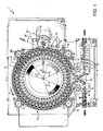
- Figure 1 illustrates a typical roll-fed labelling machine 1 for applying sleeve labels 2 (see Figures 2 and 3 ) to respective articles 3, in particular containers such as bottles, each of which ( Figures 1 to 3 ) has a given longitudinal axis A, is bonded at the bottom by a bottom wall 4 substantially perpendicular to axis A, and has a top neck 5 substantially coaxial with axis A.
- Labelling machine 1 comprises a conveying device for bending and welding labelling web material portions in a tubular configuration so as to form sleeve labels 2, and for producing the insertion of containers 3 into said sleeve labels 2.
- the conveying device comprises a carousel 7, which is mounted to rotate continuously (anticlockwise in Figure 1 ) about a respective vertical axis B perpendicular to the plane of Figure 1 .
- Carousel 7 receives a succession of unlabelled bottles 3 from an input wheel 8, which cooperates with carousel 7 at a first transfer station 9 and is mounted to rotate continuously about a respective longitudinal axis C parallel to axis B.
- Carousel 7 also receives a succession of rectangular or square portions 2 of labelling web material from an input drum 10, which cooperates with carousel 7 at a second transfer station 11 and is mounted to rotate continuously about a respective longitudinal axis D parallel to axes B and C.
- Carousel 7 releases a succession of labelled bottles 3 to an output wheel 12, which cooperates with carousel 7 at a third transfer station 13 and is mounted to rotate continuously about a respective longitudinal axis E parallel to axes B, C and D.
- Carousel 7 comprises a number of operating units 15, which are equally spaced about axis B, are mounted at the periphery of carousel 7, by which they are moved along a circular path portion P extending about axis B and through transfer station 9, 11 and 13.
- transfer station 11 is arranged, along path P, downstream from transfer station 9 and upstream from transfer station 13.
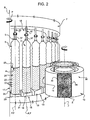
- each operating unit 15 comprises a conveying module 16 adapted to receive a relative bottle 3 from input wheel 8 in a vertical position, i.e. with the relative axis A parallel to axes B, C, D, and to hold said bottle 3 in such position along path P from transfer station 9 to transfer station 13.
- Each conveying module 16 comprises a bottom supporting assembly 17 adapted to support the bottom wall 4 of a relative bottle 3 and an upper retainer 18 adapted to cooperate with the top neck 5 of the bottle 3.
- each supporting assembly 17 comprises:
- each winding body 22 can be moved along axis F in a known manner, under the control of cam means (not shown), between a fully retracted position within the relative supporting mount 20 and a raised position ( Figures 2 to 5 ).
- each winding body 22 is completely housed within the relative supporting mount 20 so that its top surface 23 is flush with a top surface 25 of the supporting mount 20.
- each winding body 22 protrudes from the top surface 25 of the relative supporting mount 20 and is adapted to receive, on its lateral surface 24, a relative label 2 from input drum 10.
- labelling web material portions 2 are cut in a known manner from a web 26 ( Figure 1 ) by a cutting device 27 (only schematically shown in Figure 1 ) and fed to input drum 10 to be then transferred to the relative winding bodies 22.
- lateral surface 30 of input drum 10 is divided into a given number, e.g. three in the embodiment shown, of suction regions 31, which are equally spaced about axis D, are each provided with a plurality of through holes 32 connected to a pneumatic suction device (known per se and not shown) and are adapted to cooperate with respective portions of labelling web material 2.
- a pneumatic suction device known per se and not shown
- each winding body 22 is provided with a plurality of through holes 33, in turn connected to a pneumatic suction device (known per se and not shown) so as to retain the relative portion 2 of labelling web material by suction.
- a pneumatic suction device known per se and not shown
- each winding body 22 can be rotated in a known manner about the relative axis F under the control of relative actuator means (not shown) in order to produce the complete wrapping of the relative labelling web material portion 2, coming from input drum 10, on lateral surface 24. More specifically, each labelling web material portion 2, fed by input drum 10, is wrapped around the relative winding body 22 so as to form a substantially tubular sleeve with the opposite ends 34 overlapping.
- each retainer 18 comprises, in a known manner, a cylindrical movable member 36, which protrudes vertically from an upper portion of rotary frame 21 of carousel 7, can be displaced along the relative axis F and has a bell-shaped free end portion 37 adapted to cooperate with the top neck 5 of the bottle 3 carried by the corresponding bottom supporting assembly 17.
- each movable member 36 is controlled in a known manner so as to maintain the same distance between its relative end portion 37 and the top surface 23 of the corresponding winding body 22, during the movement of the relative unit 15 along the segment of path portion P from transfer station 9 to transfer station 13, and to increase such distance at transfer stations 9, 13 and during the portion of path P from station 13 to station 9.
- containers 3 are securely held in the vertical position as they travel from station 9 to station 13 and are free to be transferred at stations 9 and 13 from input wheel 8 and to output wheel 12, respectively.
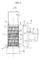
- each operating unit 15 comprises a respective sealing device 40 arranged in front of, and in a position radially inner than, the relative conveying module 16; each sealing device 40 being adapted to cooperate with the portion 2 of labelling web material wrapped around the corresponding winding body 22 for welding the overlapping ends 34 thereof so as to produce a sleeve label 2'.
- Each sealing device 40 basically comprises:
- Each sealing element 41 typically comprises a rectilinear bar-shaped main portion 45 which defines the afore-mentioned working surface 42.
- each sealing element 41 is preferably formed by a longitudinal body 50, which defines internally a cooling conduit (not shown), continuously supplied with a refrigerant, such as water, from a cooler (not shown), and is externally covered by a heating layer, which can be heated by the electrical power supplying means 43 mentioned before.
- a refrigerant such as water
- the temperature of working surface 42 is advantageously controllable.
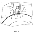
- working surface 42 comprises (see Figures 4 and 5 ) at least a first and a second region R' and R", substantially adjacent to one another, independently and controllably heatable to respective first and second operative temperatures T1 and T2, second temperature T2 being lower than first temperature T1.
- First region R' i.e. the region configured to reach the highest temperature T1 among all regions
- second region R' i.e. the region configured to reach the lowest temperature among all regions
- portion 2 of labelling web material wrapped around wingding body 22 is adapted to cooperate with portion 2 of labelling web material wrapped around wingding body 22 at a second corresponding sleeve label region S" over only a part of which ends 34 overlap.
- the working surface 42 shall cooperate with two superimposed layers of labelling web material, this condition ensuring the proper sealing of sleeve label 2'.
- cooperation of first region R' of working surface 42 with first sleeve region S' of labelling web material portion 2 shall produce a welding of the overlapping ends thereof such as to properly result in the formation of a sleeve label 2', whereas cooperation of second region R" of working surface 42 with second sleeve region S" of labelling web material portion 2 shall produce the fixing of very trailing edge 34TE (i.e. the excess amount of labelling web material of conventional methods and units) to the lateral surface of sleeve label 2'.
- working region 42 comprises at least one further region R"', adjacent to either of first and second regions R' and R" and controllably heatable, in a manner independent of first and second regions R' and R", to a respective further operative temperature T3.
- all three regions have substantially the same area.
- all three regions R', R" and R"' are configured to reach three different operative temperatures T1, T2, T3; further region R"' being adjacent to second region R" on the side opposite first region R'; T1 being higher than T2; T2 being, in turn, higher than T3.
- operative temperatures may be in the following ranges:
- operative temperatures T1, T2 and T3 shall typically fall in a wider ranger, e.g. from 50 to 500°C depending basically on the nature of the labelling web material being handled.
- the region configured to reach the highest temperature T1 (i.e. R') shall be configured to cooperate with portion 2 of labelling web material wrapped around winding body 22 at a first corresponding sleeve label region S', over the whole of which ends 34 overlap, whereas the region configured to reach a lower temperature, namely T2 or T3 (i.e. R" or R"'), shall be configured to cooperate with portion 2 of labelling web material wrapped around wingding body 22 at a corresponding sleeve label region S", over only a part of which ends 34 overlap.
- T1 i.e. R'
- T2 or T3 i.e. R" or R"'
- further region R"' is adjacent to region R" on the side opposite first region R', all three regions having substantially the same area, temperature T3 reached by further region R"' being equal to second operative temperature T2 reached by second region R".
- further region R"' is adjacent to first region R' on the side opposite second region R", all three regions having substantially the same area, temperature T3 reached by further region R"' being equal to first operative temperature T1 reached by first region R".
- these three-region embodiments are equivalent to embodiments having only a first and a second controllably and independently heatable regions, one of which has an area substantially twice as large as the other.
- operating unit 15 preferably comprises sensing means (not shown) for detecting the temperature of the at least two regions of working surface 42 and a control unit U, which is:
- sealing element 41 may comprise at least two (preferably three) distinct resistors (not shown) which are thermally and electrically isolated from one another and independently controllable by means of respective control units.
- each of independent regions R', R" (and R"', where present) of working surface 42 shall be substantially defined by one corresponding resistor, hence the relative operative temperatures T1, T2 (and T3, where contemplated) shall be independently obtainable and controllable.
- sealing element 41 may comprise at least two (preferably three) distinct resistors (not shown) which differ from each other in that they are made of different materials (and therefore have different electrical resistivity) or have different sections, so that each resistor has a different overall resistance; the same voltage being controllably applied simultaneously across the terminals of all said resistors by a single control unit.
- each of independent regions R', R" (and R"', where present) of working surface 42 shall be substantially defined by one corresponding resistor, hence the gradient of operative temperatures T1, T2 (and T3, where contemplated) across regions R', R" (and R"', where present) shall substantially depend on the physical/geometric characteristics of the resistors.
- first region R' of working surface 42 With first sleeve region S' of portion 2 of labelling web material wrapped about winding body 22, the welding of the two superimposed ends 34 of portion 2 is produced, e.g. by provoking a localised melting thereof.
- second region R"(or R"' in other embodiments) of working surface 42 with second sleeve region S" of portion 2, the "excess" web material - which is substantially identified by trailing edge 34TE mentioned above, is held against and welded to the cylindrical surface of sleeve label 2'.
- the method and unit according to the invention make it possible to easily manufacture sleeve labels 2' having a particularly smooth surface, the excess labelling web material 34TE typically encountered with conventional methods being thereby conveniently welded to the cylindrical surface of sleeve label 2'.
- the characteristics of the method of the invention are such that it can be relatively easily implemented on an existing labelling machine, provided that the original operating units are replaced by forming units according to the invention.
Landscapes
- Engineering & Computer Science (AREA)
- Mechanical Engineering (AREA)
- Physics & Mathematics (AREA)
- Thermal Sciences (AREA)
- Manufacturing & Machinery (AREA)
- Labeling Devices (AREA)
- Shaping Of Tube Ends By Bending Or Straightening (AREA)
Description
- The present invention relates to a method and unit for forming tubular lengths of web material according to the preambles of
claims 1 and 3. - In particular, the invention relates to a method and unit for shaping and sealing portions of a web material which are given a tubular configuration and which are intended to be fitted onto articles (especially containers for pourable food products, such as bottles, cans and so forth) for labelling purposes.
- In the following, therefore, reference shall be made explicitly to labelling machines handling a web material for the manufacture of tubular lengths made of said web material to be used as labels.
- However, this is not intended to limit the scope of protection of the claims attached, and the method for forming tubular lengths of web material disclosed herein may be conveniently applied to other types of machines, e.g. those for wrapping articles in a film-like material.
- Labelling machines are commonly used to apply labels to containers of all sort. Very often used with bottles or other vessels destined to hold pourable food products are tubular labels (also commonly called "sleeve labels") which are obtained by:
- cutting a web unwound from a supply roll into a plurality of rectangular or square portions;
- winding each web portion in a tubular configuration such that opposite vertical edges overlap; and
- welding the overlapping edges to fix the web material in sleeve form.
- A particular type of labelling machine is known wherein each tubular label is formed about a relative cylindrical winding body (commonly called "sleeve drum") and subsequently transferred onto a relative container, e.g. by introduction of the container inside the tubular label.
- This type of labelling machine comprises a carousel rotating about a relative vertical axis to define a substantially circular path portion, along which the labelling machine receives respective successions of unlabelled containers and of rectangular or square labelling material portions from respective input wheels; allows application of sleeve labels onto corresponding containers and releases the labelled containers to an output wheel.
- More specifically, the carousel comprises a number of operating units which are equally spaced about the rotation axis, are mounted along the periphery of the carousel and are moved by the latter along the above-mentioned circular path portion.
- Each operating unit comprises a bottom supporting assembly adapted to support the bottom wall of a relative container and an upper retainer adapted to cooperate with the top portion of such container to hold it in a vertical position during the rotation of the carousel about the vertical axis.
- Each supporting assembly comprises a vertical hollow supporting mount, secured to a horizontal plane of a rotary frame of the carousel, and a cylindrical winding body, engaging the supporting mount in sliding and rotating manner with respect to its axis, and adapted to carry a relative container on its top surface and a relative label on its lateral surface.
- Each winding body is movable, e.g. under the control of cam means, between a raised position and a fully retracted position within the relative supporting mount.
- In the raised position, each winding body protrudes from a top surface of the relative supporting mount and is adapted to receive a relative label on its lateral surface from the label input wheel; in particular the label is wrapped around the winding body such that the opposite vertical edges of the label overlap one another.
- In the fully retracted position, which is reached at the container input and output wheels, the top surface of each winding body is flush with the top surface of the supporting mount so that containers are transferred onto and from the carousel along the same transfer plane.
- After the welding of the overlapped edges of a tubular label, the movement of the relative winding body from the raised position to the fully retracted position produces the insertion of the relative container inside the label, making the so obtained container ready to be transferred to the output wheel.
- For ensuring proper formation of tubular labels, the labelling web material is cut into rectangular or square portions having a length such that, when wound about respective winding bodies, their leading and trailing ends overlap, thus being weldable to one another with good reliability.
- Therefore, in practice, the rectangular or square portions of labelling web material are cut into lengths in slight excess of the perimeter of the winding body, and the overlapping ends are welded, e.g. through localised heat application by means of a sealing bar, at a predetermined distance from the very edge of the radially external end, so that the sealing bar applies heat to an area where the two ends are superimposed.
- As a result, the excess amount of labelling web material used for the making of each sleeve label - which ultimately leads to an increased overall cost - remains on the sleeve label surface eventually applied on a respective container as an irregularity, which is generally looked upon as undesirable by food industry companies, particularly for aesthetic reasons.
-
GB 2 011 344 Aclaims 1 and 3. -
JP 2009 012781 A WO 2009/125330 A2 discloses respective methods as defined in the preamble of claim 1. - It is an object of the present invention to provide a method for sealing tubular lengths of web material which allows to overcome the above drawbacks in a straightforward and low-cost manner. This object is achieved by a method as claimed in claim 1.
- Furthermore, the present invention also relates to a unit for forming tubular lengths of web material as claimed in
Claim 3 and to a labelling machine as claimed in Claim 8. - A non-limiting embodiment of the present invention will be described by way of example with reference to the accompanying drawings, in which:
-
Figure 1 shows a schematic plan view, with parts removed for clarity, of a labelling machine according to the invention; -
Figure 2 shows a larger-scale view in perspective of a label transfer portion of the labelling machine ofFigure 1 ; -
Figure 3 shows a larger-scale, partly sectioned, lateral view, with parts removed for clarity, of a forming unit according to the teachings of the invention; and -
Figure 4 shows a larger-scale, partly sectioned, top view, with parts removed for clarity, of the forming unit ofFigure 3 ; and -
Figure 5 shows a larger-scale detail of the forming unit ofFigure 4 . -
Figure 1 illustrates a typical roll-fed labelling machine 1 for applying sleeve labels 2 (seeFigures 2 and3 ) torespective articles 3, in particular containers such as bottles, each of which (Figures 1 to 3 ) has a given longitudinal axis A, is bonded at the bottom by abottom wall 4 substantially perpendicular to axis A, and has atop neck 5 substantially coaxial with axis A. - Labelling machine 1 comprises a conveying device for bending and welding labelling web material portions in a tubular configuration so as to form
sleeve labels 2, and for producing the insertion ofcontainers 3 into saidsleeve labels 2. - In the preferred embodiment as illustrated on the Figures, the conveying device comprises a
carousel 7, which is mounted to rotate continuously (anticlockwise inFigure 1 ) about a respective vertical axis B perpendicular to the plane ofFigure 1 . - Carousel 7 receives a succession of
unlabelled bottles 3 from an input wheel 8, which cooperates withcarousel 7 at a first transfer station 9 and is mounted to rotate continuously about a respective longitudinal axis C parallel to axis B. - Carousel 7 also receives a succession of rectangular or
square portions 2 of labelling web material from aninput drum 10, which cooperates withcarousel 7 at asecond transfer station 11 and is mounted to rotate continuously about a respective longitudinal axis D parallel to axes B and C. - Carousel 7 releases a succession of labelled
bottles 3 to anoutput wheel 12, which cooperates withcarousel 7 at athird transfer station 13 and is mounted to rotate continuously about a respective longitudinal axis E parallel to axes B, C and D. - Carousel 7 comprises a number of
operating units 15, which are equally spaced about axis B, are mounted at the periphery ofcarousel 7, by which they are moved along a circular path portion P extending about axis B and throughtransfer station - As shown in
Figure 1 ,transfer station 11 is arranged, along path P, downstream from transfer station 9 and upstream fromtransfer station 13. - With particular reference to
Figures 2 and3 , eachoperating unit 15 comprises aconveying module 16 adapted to receive arelative bottle 3 from input wheel 8 in a vertical position, i.e. with the relative axis A parallel to axes B, C, D, and to hold saidbottle 3 in such position along path P from transfer station 9 totransfer station 13. - Each
conveying module 16 comprises abottom supporting assembly 17 adapted to support thebottom wall 4 of arelative bottle 3 and anupper retainer 18 adapted to cooperate with thetop neck 5 of thebottle 3. - In particular, each supporting
assembly 17 comprises: - a hollow supporting
mount 20, which has a vertical axis F, parallel to axes B, C, D and E, and is secured to a horizontal plane or table of arotary frame 21 ofcarousel 7; and - a substantially
cylindrical winding body 22, engaging the supportingmount 20 in sliding and rotating manner with respect to axis F, and adapted to carry coaxially arelative bottle 3 on itstop surface 23 and arelative label 2 on itslateral surface 24. - In particular, each
winding body 22 can be moved along axis F in a known manner, under the control of cam means (not shown), between a fully retracted position within the relative supportingmount 20 and a raised position (Figures 2 to 5 ). - In the fully retracted position, each
winding body 22 is completely housed within the relative supportingmount 20 so that itstop surface 23 is flush with atop surface 25 of the supportingmount 20. - In the raised position, each
winding body 22 protrudes from thetop surface 25 of the relative supportingmount 20 and is adapted to receive, on itslateral surface 24, arelative label 2 frominput drum 10. - More specifically, labelling
web material portions 2 are cut in a known manner from a web 26 (Figure 1 ) by a cutting device 27 (only schematically shown inFigure 1 ) and fed to inputdrum 10 to be then transferred to therelative winding bodies 22. - As shown in
Figure 2 , thecut portions 2 of labelling web material are retained on thelateral surface 30 ofinput drum 10 by suction; in fact,lateral surface 30 ofinput drum 10 is divided into a given number, e.g. three in the embodiment shown, of suction regions 31, which are equally spaced about axis D, are each provided with a plurality of through holes 32 connected to a pneumatic suction device (known per se and not shown) and are adapted to cooperate with respective portions of labellingweb material 2. - In a completely analogous manner, the
lateral surface 24 of eachwinding body 22 is provided with a plurality of throughholes 33, in turn connected to a pneumatic suction device (known per se and not shown) so as to retain therelative portion 2 of labelling web material by suction. - At
transfer station 11, eachwinding body 22 can be rotated in a known manner about the relative axis F under the control of relative actuator means (not shown) in order to produce the complete wrapping of the relative labellingweb material portion 2, coming frominput drum 10, onlateral surface 24. More specifically, each labellingweb material portion 2, fed byinput drum 10, is wrapped around the relativewinding body 22 so as to form a substantially tubular sleeve with theopposite ends 34 overlapping. - As shown in
Figure 2 , eachretainer 18 comprises, in a known manner, a cylindricalmovable member 36, which protrudes vertically from an upper portion ofrotary frame 21 ofcarousel 7, can be displaced along the relative axis F and has a bell-shapedfree end portion 37 adapted to cooperate with thetop neck 5 of thebottle 3 carried by the correspondingbottom supporting assembly 17. - More specifically, the displacement of each
movable member 36 is controlled in a known manner so as to maintain the same distance between itsrelative end portion 37 and thetop surface 23 of the correspondingwinding body 22, during the movement of therelative unit 15 along the segment of path portion P from transfer station 9 totransfer station 13, and to increase such distance attransfer stations 9, 13 and during the portion of path P fromstation 13 to station 9. Thus,containers 3 are securely held in the vertical position as they travel from station 9 tostation 13 and are free to be transferred atstations 9 and 13 from input wheel 8 and to outputwheel 12, respectively. - With reference to
Figures 1 and3 , eachoperating unit 15 comprises arespective sealing device 40 arranged in front of, and in a position radially inner than, therelative conveying module 16; eachsealing device 40 being adapted to cooperate with theportion 2 of labelling web material wrapped around the correspondingwinding body 22 for welding theoverlapping ends 34 thereof so as to produce a sleeve label 2'. - Each
sealing device 40 basically comprises: - a sealing element 41 provided with a rectilinear strip-like
active working surface 42 having a height at least equal to the height of the overlappingedges 34 to be welded; - power supplying means 43 selectively connectable to the sealing element 41; and
- an
actuator assembly 44 for moving sealing element 41 to and from the relative overlapping edges 34 along a direction X transversal to path portion P. - As shown in
Figure 1 , the directions X, along which sealing elements 41 move, extend radially with respect to axis B and, therefore, orthogonally to axes B-F. - Each sealing element 41 typically comprises a rectilinear bar-shaped
main portion 45 which defines the afore-mentioned workingsurface 42. - More specifically, the
main portion 45 of each sealing element 41 is preferably formed by alongitudinal body 50, which defines internally a cooling conduit (not shown), continuously supplied with a refrigerant, such as water, from a cooler (not shown), and is externally covered by a heating layer, which can be heated by the electrical power supplying means 43 mentioned before. - The temperature of working
surface 42 is advantageously controllable. - Advantageously, working
surface 42 comprises (seeFigures 4 and5 ) at least a first and a second region R' and R", substantially adjacent to one another, independently and controllably heatable to respective first and second operative temperatures T1 and T2, second temperature T2 being lower than first temperature T1. - First region R' (i.e. the region configured to reach the highest temperature T1 among all regions) is adapted to cooperate with
portion 2 of labelling web material wrapped around windingbody 22 at a first corresponding sleeve label region S', over the whole of which ends 34 overlap (i.e. they are superimposed on one another), whereas second region R' (i.e. the region configured to reach the lowest temperature among all regions) is adapted to cooperate withportion 2 of labelling web material wrapped aroundwingding body 22 at a second corresponding sleeve label region S", over only a part of which ends 34 overlap. - In other words, substantially over the whole of first region R' the working
surface 42 shall cooperate with two superimposed layers of labelling web material, this condition ensuring the proper sealing of sleeve label 2'. - In practice, cooperation of first region R' of working
surface 42 with first sleeve region S' of labellingweb material portion 2 shall produce a welding of the overlapping ends thereof such as to properly result in the formation of a sleeve label 2', whereas cooperation of second region R" of workingsurface 42 with second sleeve region S" of labellingweb material portion 2 shall produce the fixing of very trailing edge 34TE (i.e. the excess amount of labelling web material of conventional methods and units) to the lateral surface of sleeve label 2'. - Preferably, working
region 42 comprises at least one further region R"', adjacent to either of first and second regions R' and R" and controllably heatable, in a manner independent of first and second regions R' and R", to a respective further operative temperature T3. Preferably, all three regions have substantially the same area. - More preferably, as in the embodiment shown in
Figures 4 and5 , all three regions R', R" and R"'are configured to reach three different operative temperatures T1, T2, T3; further region R"' being adjacent to second region R" on the side opposite first region R'; T1 being higher than T2; T2 being, in turn, higher than T3. - By way of example, operative temperatures may be in the following ranges:
- T1 from 200 to 250 °C and T2 from 150 to 200 °C (in a two-region embodiment);
- T1 from 200 to 250 °C, T2 from 150 to 200 °C, T3 from 100 to 150 °C (in a three-region embodiment).
- In more general terms, operative temperatures T1, T2 and T3 shall typically fall in a wider ranger, e.g. from 50 to 500°C depending basically on the nature of the labelling web material being handled.
- Accordingly, in this embodiment, the region configured to reach the highest temperature T1 (i.e. R') shall be configured to cooperate with
portion 2 of labelling web material wrapped around windingbody 22 at a first corresponding sleeve label region S', over the whole of which ends 34 overlap, whereas the region configured to reach a lower temperature, namely T2 or T3 (i.e. R" or R"'), shall be configured to cooperate withportion 2 of labelling web material wrapped aroundwingding body 22 at a corresponding sleeve label region S", over only a part of which ends 34 overlap. - In another embodiment, further region R"' is adjacent to region R" on the side opposite first region R', all three regions having substantially the same area, temperature T3 reached by further region R"' being equal to second operative temperature T2 reached by second region R".
- In yet another embodiment, further region R"' is adjacent to first region R' on the side opposite second region R", all three regions having substantially the same area, temperature T3 reached by further region R"' being equal to first operative temperature T1 reached by first region R".
- In practice, these three-region embodiments are equivalent to embodiments having only a first and a second controllably and independently heatable regions, one of which has an area substantially twice as large as the other.
- Preferably, operating
unit 15 preferably comprises sensing means (not shown) for detecting the temperature of the at least two regions of workingsurface 42 and a control unit U, which is: - operatively connected with said sensing means and with sealing element 41, more preferably with each of the independent regions R', R" (and R"') of working
surface 42; with power supplying means 43 and withactuator assembly 44; and configured to control, accordingly, the temperature reached by each of the regions. - According to a first variant, sealing element 41 may comprise at least two (preferably three) distinct resistors (not shown) which are thermally and electrically isolated from one another and independently controllable by means of respective control units.
- Thus, each of independent regions R', R" (and R"', where present) of working
surface 42 shall be substantially defined by one corresponding resistor, hence the relative operative temperatures T1, T2 (and T3, where contemplated) shall be independently obtainable and controllable. - According to a second variant, sealing element 41 may comprise at least two (preferably three) distinct resistors (not shown) which differ from each other in that they are made of different materials (and therefore have different electrical resistivity) or have different sections, so that each resistor has a different overall resistance; the same voltage being controllably applied simultaneously across the terminals of all said resistors by a single control unit.
- Thus, each of independent regions R', R" (and R"', where present) of working
surface 42 shall be substantially defined by one corresponding resistor, hence the gradient of operative temperatures T1, T2 (and T3, where contemplated) across regions R', R" (and R"', where present) shall substantially depend on the physical/geometric characteristics of the resistors. - In use, through cooperation of first region R' of working
surface 42 with first sleeve region S' ofportion 2 of labelling web material wrapped about windingbody 22, the welding of the two superimposed ends 34 ofportion 2 is produced, e.g. by provoking a localised melting thereof. Simultaneously, cooperation of second region R"(or R"' in other embodiments) of workingsurface 42 with second sleeve region S" ofportion 2, the "excess" web material - which is substantially identified by trailing edge 34TE mentioned above, is held against and welded to the cylindrical surface of sleeve label 2'. - Accordingly, the aesthetic quality of sleeve label 2' is significantly improved.
- The advantages of the method according to the present invention will be clear from the above description.
- In particular, the method and unit according to the invention make it possible to easily manufacture sleeve labels 2' having a particularly smooth surface, the excess labelling web material 34TE typically encountered with conventional methods being thereby conveniently welded to the cylindrical surface of sleeve label 2'.
- Furthermore, the characteristics of the method of the invention are such that it can be relatively easily implemented on an existing labelling machine, provided that the original operating units are replaced by forming units according to the invention.
- Clearly, changes may be made to the method or forming
unit 15 as described and illustrated herein without, however, departing from the scope of protection as defined in the accompanying claims.
Claims (8)
- A method for forming tubular lengths of web material, comprising the steps ofa) winding a linear portion (2) of web material in a tubular configuration such that opposite vertical ends (34) of said linear portion (2) overlap; andb) welding by means of a sealing device (40) comprising a working surface (42) said overlapping ends (34) to fix said linear portion (2) of web material in sleeve configuration;characterised in that said working surface (42) comprises at least a first and a second region (R',R''), substantially adjacent to one another, independently and controllably heatable to respective first and second operative temperatures (T1, T2);
and in that said step b) comprises simultaneously the steps of:c) heating up at a selected first temperature (T1) a first region (S') of said portion (2) over the whole of which said ends (34) overlap; andd) heating up at a selected second temperature (T2) lower than said first temperature (T1) a second region (S") of said linear portion (2) adjacent to said first region (S'), said ends (34) of said linear portion (2) of labelling web material overlapping over only a part of said second region (S"). - The method according to Claim 1, characterised in that said first temperature (T1) is sufficiently high for producing the welding of said overlapping ends (34) of said linear portion (2), whereas said second temperature (T2) is sufficiently high for producing the welding of a trailing edge (34TE) of said linear portion (2) to the cylindrical surface of sleeve label (2') without causing the latter to melt.
- A unit (15) for forming tubular lengths of web material, comprising:- a winding body (22) for receiving and producing the complete wrapping of alinear portion (2) of said web material into a tubular configuration with opposite ends (34) overlapping; and- a sealing device (40) comprising a working surface (42) adapted to cooperate with said linear portion (2) of labelling web material wrapped around said winding body (22) for welding said overlapping ends (34) so as to obtain a sleeve label (2');characterised in that said working surface (42) comprises at least a first and a second region (R', R"), substantially adjacent to one another, independently and controllably heatable to respective first and second operative temperatures (T1, T2), said second temperature (T2) being lower than said first temperature (T1); the unit (15) being configured so that said first region (R') of said working surface (42) cooperates with said linear portion (2) of labelling web material wrapped around said winding body (22) at a first corresponding sleeve label region (S'), over the whole of which said ends (34) overlap and said second region (R") cooperates with said linear portion (2) of labelling web material wrapped around said winding body (22) at a second corresponding sleeve label region (S"), over only a part of which said ends (34) overlap.
- The unit according to Claim 3, characterised in that said working region (42) comprises at least one further region (R"'), adjacent to either of said first and second regions (R', R") and controllably heatable, in a manner independent of said first and second regions (R', R"), to a respective further operative temperature (T3).
- The unit according to Claim 4, characterised in that said further region (R"') is adjacent to said second region (R") on the side opposite said first region (R'); said further operative temperature (T3) being lower than said second operative temperature (T2).
- The unit according to Claim 4, characterised in that said further region (R"') is adjacent to said first region (R') on the side opposite said second region (R"); said further operative temperature (T3) being higher than said first operative temperature (T1).
- The unit according to Claim 4, characterised in that said further operative temperature (T3) is equal to said either first or second operative temperature (T1, T2)
to which said either first or second region (R', R") is heatable. - A labelling machine comprising a unit (15) for forming tubular lengths of web material according to any one of Claims 3 to 7.
Applications Claiming Priority (1)
| Application Number | Priority Date | Filing Date | Title |
|---|---|---|---|
| IT000126A ITTO20120126A1 (en) | 2012-02-13 | 2012-02-13 | METHOD AND UNIT FOR THE FORMATION OF TUBULAR SHEETS OF MATERIAL IN THE FORM OF TAPE, IN PARTICULAR IN A LABELING MACHINE |
Publications (2)
| Publication Number | Publication Date |
|---|---|
| EP2626312A1 EP2626312A1 (en) | 2013-08-14 |
| EP2626312B1 true EP2626312B1 (en) | 2014-11-05 |
Family
ID=46022576
Family Applications (1)
| Application Number | Title | Priority Date | Filing Date |
|---|---|---|---|
| EP13155141.8A Not-in-force EP2626312B1 (en) | 2012-02-13 | 2013-02-13 | Method and unit for forming tubular lengths of web material, particularly in a labelling machine |
Country Status (5)
| Country | Link |
|---|---|
| US (1) | US9233770B2 (en) |
| EP (1) | EP2626312B1 (en) |
| JP (1) | JP2013209156A (en) |
| CN (1) | CN103241422B (en) |
| IT (1) | ITTO20120126A1 (en) |
Families Citing this family (3)
| Publication number | Priority date | Publication date | Assignee | Title |
|---|---|---|---|---|
| EP2889229B1 (en) | 2013-12-31 | 2016-09-21 | Sidel S.p.a. Con Socio Unico | A machine for processing containers having an improved control architecture |
| US10464705B2 (en) * | 2015-09-28 | 2019-11-05 | Maheshkumar Jayantilal Mevada | Discarding defective label |
| CN106226674B (en) * | 2016-09-25 | 2019-01-11 | 江苏前瑞智能系统集成有限公司 | A kind of IC chip detection device |
Family Cites Families (15)
| Publication number | Priority date | Publication date | Assignee | Title |
|---|---|---|---|---|
| JPS5833813B2 (en) * | 1977-12-19 | 1983-07-22 | 東洋ガラス株式会社 | Plastic sleeve manufacturing method and device |
| US4581262A (en) * | 1985-01-14 | 1986-04-08 | Owens-Illinois, Inc. | Coextruded multilayer sheet and sleeve label made therefrom |
| CN85101771A (en) * | 1985-04-01 | 1987-01-31 | 欧文斯-伊利诺衣公司 | Post the method for the container and the adhesive label of plastic label |
| DE4125472A1 (en) * | 1991-08-01 | 1993-02-04 | Kronseder Maschf Krones | METHOD AND DEVICE FOR EQUIPPING VESSELS WITH A LABEL FROM SEALABLE MATERIAL AND VESSELS EQUIPPED THEREFORE |
| US5472549A (en) * | 1994-07-08 | 1995-12-05 | Enclosure Technologies, Inc. | Apparatus for electronically seam fusing dissimilar polymeric materials |
| US6881929B2 (en) * | 2002-04-25 | 2005-04-19 | Idolon Technologies | Portable heat sealer |
| ITPR20020049A1 (en) * | 2002-08-27 | 2004-02-28 | Simonazzi S P A Gia Sig Simonazzi Spa | PROCEDURE FOR FORMING TUBULAR LABELS IN HEAT-SHRINK FILM AND MACHINE FOR FORMING LABELS AND INSERTING BOTTLES OR CONTAINERS IN GENERAL INSIDE THE FORMED LABELS. |
| ITMO20060203A1 (en) * | 2006-06-22 | 2007-12-23 | Sacmi Labelling S P A | APPARATUS AND METHOD FOR LABELING |
| JP2008238682A (en) * | 2007-03-28 | 2008-10-09 | Fujifilm Corp | Method for stretching polymer film |
| JP5088019B2 (en) * | 2007-06-29 | 2012-12-05 | 大日本印刷株式会社 | Cylindrical shrink label, container with cylindrical shrink label, and manufacturing method thereof |
| JP5258221B2 (en) * | 2007-07-30 | 2013-08-07 | 富士フイルム株式会社 | Polymer film joining method and apparatus, polymer film stretching method and equipment |
| PL2276622T3 (en) * | 2008-04-10 | 2017-04-28 | Aisapack Holding Sa | Method for manufacturing tubes by welding |
| CA2738712A1 (en) * | 2008-10-08 | 2010-04-15 | Sidel S.P.A. | Labelling machine for sleeve labels |
| JP5317123B2 (en) * | 2009-09-17 | 2013-10-16 | 株式会社フジシール | Heat-shrinkable cylindrical multi-label and container with heat-shrinkable cylindrical multi-label |
| CN102139776B (en) * | 2011-03-29 | 2012-07-04 | 东莞市正新包装制品有限公司 | Method for sleeving thermal shrinkage film label on conical cup |
-
2012
- 2012-02-13 IT IT000126A patent/ITTO20120126A1/en unknown
-
2013
- 2013-02-12 US US13/765,333 patent/US9233770B2/en not_active Expired - Fee Related
- 2013-02-13 JP JP2013025431A patent/JP2013209156A/en active Pending
- 2013-02-13 EP EP13155141.8A patent/EP2626312B1/en not_active Not-in-force
- 2013-02-18 CN CN201310052863.9A patent/CN103241422B/en not_active Expired - Fee Related
Also Published As
| Publication number | Publication date |
|---|---|
| US9233770B2 (en) | 2016-01-12 |
| US20130206326A1 (en) | 2013-08-15 |
| CN103241422B (en) | 2016-05-18 |
| EP2626312A1 (en) | 2013-08-14 |
| ITTO20120126A1 (en) | 2013-08-14 |
| CN103241422A (en) | 2013-08-14 |
| JP2013209156A (en) | 2013-10-10 |
Similar Documents
| Publication | Publication Date | Title |
|---|---|---|
| EP2464569B1 (en) | A labelling machine for applying tubular labels to respective articles | |
| US9522757B2 (en) | Method and unit for forming tubular lengths of web material particularly in a labelling machine | |
| US8899294B2 (en) | Labelling machine for sleeve labels | |
| US9296507B2 (en) | Vacuum transfer element and method for transferring tubular labels | |
| US9193493B2 (en) | Labelling machine | |
| EP2626312B1 (en) | Method and unit for forming tubular lengths of web material, particularly in a labelling machine | |
| EP2669203B1 (en) | Labelling machine and method | |
| EP2428355B1 (en) | A method and a machine for producing a container, in particular a container for pourable food products | |
| EP2542477B1 (en) | Labelling machine and method thereof | |
| EP2883804B1 (en) | A labelling unit for applying a label onto an article | |
| EP2883805A1 (en) | A labelling unit and a method for applying a label onto a non-cylindrical label receiving portion of an article | |
| EP2673199B1 (en) | A unit for applying a label on a relative article |
Legal Events
| Date | Code | Title | Description |
|---|---|---|---|
| PUAI | Public reference made under article 153(3) epc to a published international application that has entered the european phase |
Free format text: ORIGINAL CODE: 0009012 |
|
| AK | Designated contracting states |
Kind code of ref document: A1 Designated state(s): AL AT BE BG CH CY CZ DE DK EE ES FI FR GB GR HR HU IE IS IT LI LT LU LV MC MK MT NL NO PL PT RO RS SE SI SK SM TR |
|
| AX | Request for extension of the european patent |
Extension state: BA ME |
|
| 17P | Request for examination filed |
Effective date: 20131227 |
|
| RBV | Designated contracting states (corrected) |
Designated state(s): AL AT BE BG CH CY CZ DE DK EE ES FI FR GB GR HR HU IE IS IT LI LT LU LV MC MK MT NL NO PL PT RO RS SE SI SK SM TR |
|
| GRAP | Despatch of communication of intention to grant a patent |
Free format text: ORIGINAL CODE: EPIDOSNIGR1 |
|
| INTG | Intention to grant announced |
Effective date: 20140331 |
|
| GRAP | Despatch of communication of intention to grant a patent |
Free format text: ORIGINAL CODE: EPIDOSNIGR1 |
|
| INTG | Intention to grant announced |
Effective date: 20140812 |
|
| GRAS | Grant fee paid |
Free format text: ORIGINAL CODE: EPIDOSNIGR3 |
|
| GRAA | (expected) grant |
Free format text: ORIGINAL CODE: 0009210 |
|
| AK | Designated contracting states |
Kind code of ref document: B1 Designated state(s): AL AT BE BG CH CY CZ DE DK EE ES FI FR GB GR HR HU IE IS IT LI LT LU LV MC MK MT NL NO PL PT RO RS SE SI SK SM TR |
|
| REG | Reference to a national code |
Ref country code: GB Ref legal event code: FG4D |
|
| REG | Reference to a national code |
Ref country code: CH Ref legal event code: EP |
|
| REG | Reference to a national code |
Ref country code: AT Ref legal event code: REF Ref document number: 694468 Country of ref document: AT Kind code of ref document: T Effective date: 20141115 |
|
| REG | Reference to a national code |
Ref country code: IE Ref legal event code: FG4D |
|
| REG | Reference to a national code |
Ref country code: DE Ref legal event code: R096 Ref document number: 602013000416 Country of ref document: DE Effective date: 20141218 |
|
| REG | Reference to a national code |
Ref country code: FR Ref legal event code: PLFP Year of fee payment: 3 |
|
| REG | Reference to a national code |
Ref country code: AT Ref legal event code: MK05 Ref document number: 694468 Country of ref document: AT Kind code of ref document: T Effective date: 20141105 |
|
| REG | Reference to a national code |
Ref country code: NL Ref legal event code: VDEP Effective date: 20141105 |
|
| REG | Reference to a national code |
Ref country code: LT Ref legal event code: MG4D |
|
| PG25 | Lapsed in a contracting state [announced via postgrant information from national office to epo] |
Ref country code: NL Free format text: LAPSE BECAUSE OF FAILURE TO SUBMIT A TRANSLATION OF THE DESCRIPTION OR TO PAY THE FEE WITHIN THE PRESCRIBED TIME-LIMIT Effective date: 20141105 Ref country code: LT Free format text: LAPSE BECAUSE OF FAILURE TO SUBMIT A TRANSLATION OF THE DESCRIPTION OR TO PAY THE FEE WITHIN THE PRESCRIBED TIME-LIMIT Effective date: 20141105 Ref country code: ES Free format text: LAPSE BECAUSE OF FAILURE TO SUBMIT A TRANSLATION OF THE DESCRIPTION OR TO PAY THE FEE WITHIN THE PRESCRIBED TIME-LIMIT Effective date: 20141105 Ref country code: FI Free format text: LAPSE BECAUSE OF FAILURE TO SUBMIT A TRANSLATION OF THE DESCRIPTION OR TO PAY THE FEE WITHIN THE PRESCRIBED TIME-LIMIT Effective date: 20141105 Ref country code: NO Free format text: LAPSE BECAUSE OF FAILURE TO SUBMIT A TRANSLATION OF THE DESCRIPTION OR TO PAY THE FEE WITHIN THE PRESCRIBED TIME-LIMIT Effective date: 20150205 Ref country code: PT Free format text: LAPSE BECAUSE OF FAILURE TO SUBMIT A TRANSLATION OF THE DESCRIPTION OR TO PAY THE FEE WITHIN THE PRESCRIBED TIME-LIMIT Effective date: 20150305 Ref country code: IS Free format text: LAPSE BECAUSE OF FAILURE TO SUBMIT A TRANSLATION OF THE DESCRIPTION OR TO PAY THE FEE WITHIN THE PRESCRIBED TIME-LIMIT Effective date: 20150305 |
|
| PG25 | Lapsed in a contracting state [announced via postgrant information from national office to epo] |
Ref country code: RS Free format text: LAPSE BECAUSE OF FAILURE TO SUBMIT A TRANSLATION OF THE DESCRIPTION OR TO PAY THE FEE WITHIN THE PRESCRIBED TIME-LIMIT Effective date: 20141105 Ref country code: LV Free format text: LAPSE BECAUSE OF FAILURE TO SUBMIT A TRANSLATION OF THE DESCRIPTION OR TO PAY THE FEE WITHIN THE PRESCRIBED TIME-LIMIT Effective date: 20141105 Ref country code: HR Free format text: LAPSE BECAUSE OF FAILURE TO SUBMIT A TRANSLATION OF THE DESCRIPTION OR TO PAY THE FEE WITHIN THE PRESCRIBED TIME-LIMIT Effective date: 20141105 Ref country code: AT Free format text: LAPSE BECAUSE OF FAILURE TO SUBMIT A TRANSLATION OF THE DESCRIPTION OR TO PAY THE FEE WITHIN THE PRESCRIBED TIME-LIMIT Effective date: 20141105 Ref country code: CY Free format text: LAPSE BECAUSE OF FAILURE TO SUBMIT A TRANSLATION OF THE DESCRIPTION OR TO PAY THE FEE WITHIN THE PRESCRIBED TIME-LIMIT Effective date: 20141105 Ref country code: PL Free format text: LAPSE BECAUSE OF FAILURE TO SUBMIT A TRANSLATION OF THE DESCRIPTION OR TO PAY THE FEE WITHIN THE PRESCRIBED TIME-LIMIT Effective date: 20141105 Ref country code: GR Free format text: LAPSE BECAUSE OF FAILURE TO SUBMIT A TRANSLATION OF THE DESCRIPTION OR TO PAY THE FEE WITHIN THE PRESCRIBED TIME-LIMIT Effective date: 20150206 Ref country code: SE Free format text: LAPSE BECAUSE OF FAILURE TO SUBMIT A TRANSLATION OF THE DESCRIPTION OR TO PAY THE FEE WITHIN THE PRESCRIBED TIME-LIMIT Effective date: 20141105 |
|
| PG25 | Lapsed in a contracting state [announced via postgrant information from national office to epo] |
Ref country code: SK Free format text: LAPSE BECAUSE OF FAILURE TO SUBMIT A TRANSLATION OF THE DESCRIPTION OR TO PAY THE FEE WITHIN THE PRESCRIBED TIME-LIMIT Effective date: 20141105 Ref country code: DK Free format text: LAPSE BECAUSE OF FAILURE TO SUBMIT A TRANSLATION OF THE DESCRIPTION OR TO PAY THE FEE WITHIN THE PRESCRIBED TIME-LIMIT Effective date: 20141105 Ref country code: CZ Free format text: LAPSE BECAUSE OF FAILURE TO SUBMIT A TRANSLATION OF THE DESCRIPTION OR TO PAY THE FEE WITHIN THE PRESCRIBED TIME-LIMIT Effective date: 20141105 Ref country code: EE Free format text: LAPSE BECAUSE OF FAILURE TO SUBMIT A TRANSLATION OF THE DESCRIPTION OR TO PAY THE FEE WITHIN THE PRESCRIBED TIME-LIMIT Effective date: 20141105 |
|
| REG | Reference to a national code |
Ref country code: DE Ref legal event code: R097 Ref document number: 602013000416 Country of ref document: DE |
|
| PLBE | No opposition filed within time limit |
Free format text: ORIGINAL CODE: 0009261 |
|
| STAA | Information on the status of an ep patent application or granted ep patent |
Free format text: STATUS: NO OPPOSITION FILED WITHIN TIME LIMIT |
|
| PG25 | Lapsed in a contracting state [announced via postgrant information from national office to epo] |
Ref country code: LU Free format text: LAPSE BECAUSE OF FAILURE TO SUBMIT A TRANSLATION OF THE DESCRIPTION OR TO PAY THE FEE WITHIN THE PRESCRIBED TIME-LIMIT Effective date: 20150213 |
|
| 26N | No opposition filed |
Effective date: 20150806 |
|
| PG25 | Lapsed in a contracting state [announced via postgrant information from national office to epo] |
Ref country code: MC Free format text: LAPSE BECAUSE OF FAILURE TO SUBMIT A TRANSLATION OF THE DESCRIPTION OR TO PAY THE FEE WITHIN THE PRESCRIBED TIME-LIMIT Effective date: 20141105 |
|
| REG | Reference to a national code |
Ref country code: IE Ref legal event code: MM4A |
|
| PG25 | Lapsed in a contracting state [announced via postgrant information from national office to epo] |
Ref country code: IT Free format text: LAPSE BECAUSE OF FAILURE TO SUBMIT A TRANSLATION OF THE DESCRIPTION OR TO PAY THE FEE WITHIN THE PRESCRIBED TIME-LIMIT Effective date: 20141105 |
|
| REG | Reference to a national code |
Ref country code: FR Ref legal event code: PLFP Year of fee payment: 4 |
|
| PG25 | Lapsed in a contracting state [announced via postgrant information from national office to epo] |
Ref country code: IE Free format text: LAPSE BECAUSE OF NON-PAYMENT OF DUE FEES Effective date: 20150213 |
|
| PG25 | Lapsed in a contracting state [announced via postgrant information from national office to epo] |
Ref country code: SI Free format text: LAPSE BECAUSE OF FAILURE TO SUBMIT A TRANSLATION OF THE DESCRIPTION OR TO PAY THE FEE WITHIN THE PRESCRIBED TIME-LIMIT Effective date: 20141105 |
|
| PG25 | Lapsed in a contracting state [announced via postgrant information from national office to epo] |
Ref country code: RO Free format text: LAPSE BECAUSE OF FAILURE TO SUBMIT A TRANSLATION OF THE DESCRIPTION OR TO PAY THE FEE WITHIN THE PRESCRIBED TIME-LIMIT Effective date: 20141105 |
|
| REG | Reference to a national code |
Ref country code: CH Ref legal event code: PL |
|
| PG25 | Lapsed in a contracting state [announced via postgrant information from national office to epo] |
Ref country code: LI Free format text: LAPSE BECAUSE OF NON-PAYMENT OF DUE FEES Effective date: 20160229 Ref country code: CH Free format text: LAPSE BECAUSE OF NON-PAYMENT OF DUE FEES Effective date: 20160229 |
|
| PG25 | Lapsed in a contracting state [announced via postgrant information from national office to epo] |
Ref country code: MT Free format text: LAPSE BECAUSE OF FAILURE TO SUBMIT A TRANSLATION OF THE DESCRIPTION OR TO PAY THE FEE WITHIN THE PRESCRIBED TIME-LIMIT Effective date: 20141105 |
|
| REG | Reference to a national code |
Ref country code: FR Ref legal event code: PLFP Year of fee payment: 5 |
|
| PG25 | Lapsed in a contracting state [announced via postgrant information from national office to epo] |
Ref country code: BG Free format text: LAPSE BECAUSE OF FAILURE TO SUBMIT A TRANSLATION OF THE DESCRIPTION OR TO PAY THE FEE WITHIN THE PRESCRIBED TIME-LIMIT Effective date: 20141105 Ref country code: HU Free format text: LAPSE BECAUSE OF FAILURE TO SUBMIT A TRANSLATION OF THE DESCRIPTION OR TO PAY THE FEE WITHIN THE PRESCRIBED TIME-LIMIT; INVALID AB INITIO Effective date: 20130213 |
|
| PG25 | Lapsed in a contracting state [announced via postgrant information from national office to epo] |
Ref country code: TR Free format text: LAPSE BECAUSE OF FAILURE TO SUBMIT A TRANSLATION OF THE DESCRIPTION OR TO PAY THE FEE WITHIN THE PRESCRIBED TIME-LIMIT Effective date: 20141105 |
|
| PG25 | Lapsed in a contracting state [announced via postgrant information from national office to epo] |
Ref country code: BE Free format text: LAPSE BECAUSE OF FAILURE TO SUBMIT A TRANSLATION OF THE DESCRIPTION OR TO PAY THE FEE WITHIN THE PRESCRIBED TIME-LIMIT Effective date: 20141105 |
|
| GBPC | Gb: european patent ceased through non-payment of renewal fee |
Effective date: 20170213 |
|
| REG | Reference to a national code |
Ref country code: FR Ref legal event code: PLFP Year of fee payment: 6 |
|
| PG25 | Lapsed in a contracting state [announced via postgrant information from national office to epo] |
Ref country code: GB Free format text: LAPSE BECAUSE OF NON-PAYMENT OF DUE FEES Effective date: 20170213 |
|
| PG25 | Lapsed in a contracting state [announced via postgrant information from national office to epo] |
Ref country code: SM Free format text: LAPSE BECAUSE OF FAILURE TO SUBMIT A TRANSLATION OF THE DESCRIPTION OR TO PAY THE FEE WITHIN THE PRESCRIBED TIME-LIMIT Effective date: 20141105 |
|
| PG25 | Lapsed in a contracting state [announced via postgrant information from national office to epo] |
Ref country code: MK Free format text: LAPSE BECAUSE OF FAILURE TO SUBMIT A TRANSLATION OF THE DESCRIPTION OR TO PAY THE FEE WITHIN THE PRESCRIBED TIME-LIMIT Effective date: 20141105 |
|
| PG25 | Lapsed in a contracting state [announced via postgrant information from national office to epo] |
Ref country code: AL Free format text: LAPSE BECAUSE OF FAILURE TO SUBMIT A TRANSLATION OF THE DESCRIPTION OR TO PAY THE FEE WITHIN THE PRESCRIBED TIME-LIMIT Effective date: 20141105 |
|
| PGFP | Annual fee paid to national office [announced via postgrant information from national office to epo] |
Ref country code: DE Payment date: 20200121 Year of fee payment: 8 |
|
| PGFP | Annual fee paid to national office [announced via postgrant information from national office to epo] |
Ref country code: FR Payment date: 20200122 Year of fee payment: 8 |
|
| REG | Reference to a national code |
Ref country code: DE Ref legal event code: R119 Ref document number: 602013000416 Country of ref document: DE |
|
| PG25 | Lapsed in a contracting state [announced via postgrant information from national office to epo] |
Ref country code: FR Free format text: LAPSE BECAUSE OF NON-PAYMENT OF DUE FEES Effective date: 20210228 Ref country code: DE Free format text: LAPSE BECAUSE OF NON-PAYMENT OF DUE FEES Effective date: 20210901 |