EP2626302A1 - System and method of actuating a swashplate for main rotor control - Google Patents
System and method of actuating a swashplate for main rotor control Download PDFInfo
- Publication number
- EP2626302A1 EP2626302A1 EP12159732.2A EP12159732A EP2626302A1 EP 2626302 A1 EP2626302 A1 EP 2626302A1 EP 12159732 A EP12159732 A EP 12159732A EP 2626302 A1 EP2626302 A1 EP 2626302A1
- Authority
- EP
- European Patent Office
- Prior art keywords
- piston
- cylinder assembly
- triplex actuator
- triplex
- actuator
- Prior art date
- Legal status (The legal status is an assumption and is not a legal conclusion. Google has not performed a legal analysis and makes no representation as to the accuracy of the status listed.)
- Granted
Links
Images

Classifications
-
- B—PERFORMING OPERATIONS; TRANSPORTING
- B64—AIRCRAFT; AVIATION; COSMONAUTICS
- B64C—AEROPLANES; HELICOPTERS
- B64C27/00—Rotorcraft; Rotors peculiar thereto
- B64C27/54—Mechanisms for controlling blade adjustment or movement relative to rotor head, e.g. lag-lead movement
- B64C27/58—Transmitting means, e.g. interrelated with initiating means or means acting on blades
- B64C27/59—Transmitting means, e.g. interrelated with initiating means or means acting on blades mechanical
- B64C27/605—Transmitting means, e.g. interrelated with initiating means or means acting on blades mechanical including swash plate, spider or cam mechanisms
-
- F—MECHANICAL ENGINEERING; LIGHTING; HEATING; WEAPONS; BLASTING
- F15—FLUID-PRESSURE ACTUATORS; HYDRAULICS OR PNEUMATICS IN GENERAL
- F15B—SYSTEMS ACTING BY MEANS OF FLUIDS IN GENERAL; FLUID-PRESSURE ACTUATORS, e.g. SERVOMOTORS; DETAILS OF FLUID-PRESSURE SYSTEMS, NOT OTHERWISE PROVIDED FOR
- F15B18/00—Parallel arrangements of independent servomotor systems
Definitions
- the present application relates in general to a control system for an aircraft. More specifically, the present application relates to a main rotor control system for a rotorcraft.
- rotorcraft main control systems are designed with many factors in consideration.
- One conventional main rotor system uses a plurality of mechanical linkages in conjunction with hydraulic actuators to selectively impart pitch control inputs in the rotor system.
- the devices, members, apparatuses, etc. described herein may be positioned in any desired orientation.
- the use of terms such as “above,” “below,” “upper,” “lower,” or other like terms to describe a spatial relationship between various components or to describe the spatial orientation of aspects of such components should be understood to describe a relative relationship between the components or a spatial orientation of aspects of such components, respectively, as the device described herein may be oriented in any desired direction.
- Rotorcraft 101 has a rotor system 103 with a plurality of rotor blades 111.
- Rotorcraft 101 further includes a fuselage 105, landing gear 107, and an empennage 109.
- a main rotor control system 113 can be used to selectively control the pitch of each rotor blade 111 in order to selectively control direction, thrust, and lift of rotorcraft 101, as discussed further herein.
- main rotor control system 113 is depicted on a rotorcraft 101 that has certain illustrated features, it should be appreciated that main rotor control system 113 can be implemented on other rotorcraft and rotorcraft configurations, as one of ordinary skill in the art would fully appreciate having the benefit of this disclosure. Further, it should be appreciated that main rotor control system 113 can be implemented to control a variety of rotor blade quantities. Referring now also to Figure 2 , main rotor control system 113 is illustrated in further detail. Control system 113 includes three triplex actuators 115a-115c coupled to a rise/fall swashplate assembly 131.
- Swashplate assembly 131 includes a rotating swashplate ring 123 and a non-rotating swashplate ring 125.
- Rotating swashplate ring 123 has a plurality of pitch-link attachment members 127, each being configured for attaching a pitch-link 129 (only one illustrated for clarity).
- Each pitch-link 129 is coupled between rotating swashplate ring 123 and a pitch horn member of a rotor blade, such as rotor blade 111.
- a quantity of pitch-link attachment members 127 corresponds with the number of rotor blades 111.
- pitch-link attachment members 127 are located equidistant around the perimeter of rotating swashplate ring 123.
- Rotor mast (not shown for clarity) is coupled to the rotating swashplate ring 123 via a spline, the rotational axis of the mast being mast axis 121.
- non-rotating swashplate ring 125 is configured to receive actuation inputs from triplex actuators 115a-115c, and mechanically transfer said inputs into rotating swashplate ring 123 via a bearing assembly.
- Each triplex actuator 115a-115c is coupled to non-rotating swashplate ring 125 at an individual location.
- the three attachment locations on non-rotating swashplate ring 125 are located at non-uniform spacing intervals about the mast axis; however, in an alternative embodiment the three attachment locations are equidistant 120° spaced locations about the mast axis.
- Control system 113 is configured such that triplex actuators 115a-115c are selectively actuated to provide full collective and cyclic movements of rotating swashplate ring 123.
- a collective input from triplex actuators 115a-115c translates swashplate assembly 131 substantially along mast axis 121 so as to uniformly change the pitch of each rotor blade through a corresponding pitch link 129.
- a cyclic input selectively tilts swashplate assembly 131 about a lateral tilt axis 117, a longitudinal tilt axis 119, or any combination thereof. It should be appreciated that the exact orientation of lateral tilt axis 117 and longitudinal tilt axis 119 in relation to an axis of the aircraft is implementation specific. It should be fully appreciated that full cyclic and collective movements of swashplate assembly 131 are actuated by triplex actuators 115a-115c. A lower portion of each triplex actuator 115a-115c is coupled to a fixed portion of rotorcraft 101, such as a gearbox, pylon mount, or roof deck, to name a few examples.
- triplex actuators 115a-115c are controlled in a fly-by-wire flight control configuration. Flight control inputs from a pilot are converted to actuation inputs to triplex actuators 115a-115c in order to cause selective actuation of rise/fall swashplate assembly 131. In an alternative embodiment, an unmanned flight control system is used in lieu of the pilot. When a collective input is made, each triplex actuator 115a-115c is actuated to translate rise/fall swashplate assembly 131 uniformly upwards or downwards along mast axis 121, thereby uniformly increasing or decreasing the pitch of each rotor blade 111.
- triplex actuators 115a-115c are actuated to cause a tilting of rise/fall swashplate assembly 131 about lateral tilt axis 117, longitudinal tilt axis 119, or any combination of tilting about lateral tilt axis 117 and longitudinal tilt axis 119. Because the cyclic input can be made to tilt rise/fall swashplate assembly 131 about lateral tilt axis 117 as well as longitudinal tilt axis 119, a variety of flight maneuvers can be realized, such as a change in rotorcraft pitch and roll, as well as combinations thereof.
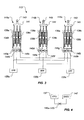
- Each triplex actuator 115a, 115b, and 115c include three separate piston/cylinder assemblies 139a-139c.
- Each piston/cylinder assembly 139a-139c is coupled to a yoke 141.
- Yoke 141 is coupled to a rod end 143 configured for coupling to non-rotating swashplate ring 125.
- Triplex actuator 115a has a manifold 145a-145c associated with each piston/cylinder assembly 139a-139c, respectively.
- triplex actuator 115b has a manifold 145d-145f associated with each piston/cylinder assembly 139a-139c, respectively.
- triplex actuator 115c has a manifold 145g-145i associated with each piston/cylinder assembly 139a-139c, respectively.
- Manifolds 145a, 145d, and 145g are in hydraulic communication with a hydraulic power pack (HPP) 135a.
- Manifolds 145b, 145e, and 145h are in hydraulic communication with a hydraulic power pack (HPP) 135b.
- Manifolds 145c, 145f, and 145i are in hydraulic communication with a hydraulic power pack (HPP) 135c.
- Each piston/cylinder assembly 139a-139c is hydraulically actuated in parallel so that the rod member in each piston/cylinder assembly 139a-139c can be translated in parallel.
- Hydraulic power packs 135a-135c are each independent hydraulic systems configured to collectively provide redundancy.
- Each hydraulic power pack 135a-135c includes a pump and reservoir in one package.
- a flight control computer is preferably associated with a single manifold of each triplex actuator, for control thereof.
- a first of three FCC's can be associated with manifolds 145a, 145d, and 145g.
- the second of three FCC's can be associated with manifolds 145b, 145e, and 145h.
- the third of three FCC's can be associated with manifolds 145c, 145f, and 145i. It should be appreciated that the above combinations are exemplary of wide variety of FCC and manifold combinations.
- One important feature is that each FCC controls a single manifold on each triplex actuator.
- Each manifold 145a-145i preferably includes a includes an integrated three function valve (ITFV) 137 configured to allow triplex actuator 115a to operate even after a failure of one or two of piston/cylinder assemblies 139a-139c.
- ITFV 137 can be used to quickly inert a malfunctioning piston/cylinder assembly, such as piston/cylinder assembly 139a, so that the remaining healthy piston/cylinder assemblies 139b and 139c can continue to operate without fighting piston/cylinder assembly 139a.
- ITFV 137 allows a single piston/cylinder assembly to be in bypass while allowing the triplex actuator to be supplied energy via the other two hydraulic power packs.
- each ITFV allows the remaining two triplex actuators to function with all three hydraulic power packs 135a-135c.
- Each manifold 145a-145i preferably also includes an electro-hydraulic servo-valve (EHSV) 147.
- EHSV electro-hydraulic servo-valve
- a main rotor control system 113 having triplex actuators 115a-115c in conjunction with rise/fall swashplate assembly 131 provides a novel arrangement with distinct advantages.
- One advantage is that the flight control computers (FCC's) in a fly-by-wire control system can be prone to undesired glitches and/or failures, as compared to conventional mechanical systems.
- FCC's flight control computers
- triplex actuators 115a-115c with each having three parallel piston/cylinder assemblies 139a-139c. The failure of a single piston/cylinder assembly only results in a 1/3 loss of power in the triplex actuator.
- each piston/cylinder assembly 139a-139c within an individual triplex actuator is separately powered by a hydraulic power pack (HPP), thus further realizing an increased level of safety.
- HPP hydraulic power pack
- rise/fall swashplate assembly 131 increases the efficiencies of main rotor control system 113 by providing full collective and cyclic pitch control capabilities.
- Each triplex actuator 115a-115c is coupled between non-rotating swashplate ring 125 and a stationary structure, thus eliminating the need for heavy critical parts and linkages, the failure of which could be catastrophic.
Landscapes
- Engineering & Computer Science (AREA)
- Mechanical Engineering (AREA)
- Aviation & Aerospace Engineering (AREA)
- General Details Of Gearings (AREA)
- Control Of Turbines (AREA)
- Feedback Control In General (AREA)
Abstract
Description
- The present application relates in general to a control system for an aircraft. More specifically, the present application relates to a main rotor control system for a rotorcraft.
- Typically, rotorcraft main control systems are designed with many factors in consideration. One conventional main rotor system uses a plurality of mechanical linkages in conjunction with hydraulic actuators to selectively impart pitch control inputs in the rotor system. Although the foregoing represents a significant technology in the area main rotor control, significant room for improvement remains.
- The novel features believed characteristic of the embodiments of the present application are set forth in the appended claims. However, the embodiments themselves, as well as a preferred mode of use, and further objectives and advantages thereof, will best be understood by reference to the following detailed description when read in conjunction with the accompanying drawings, wherein:
-
Figure 1 is a side view of a rotorcraft, according to an embodiment of the present application; -
Figure 2 is a perspective view of a main rotor control system, according to an embodiment of the present application; -
Figure 3 is a schematic view of the main rotor control system, according to an embodiment of the present application; and -
Figure 4 is a schematic view of a manifold member of the main rotor control system, according to an embodiment of the present application. - Illustrative embodiments of the system and method of the present application are described below. In the interest of clarity, not all features of an actual implementation are described in this specification. It will of course be appreciated that in the development of any such actual embodiment, numerous implementation-specific decisions must be made to achieve the developer's specific goals, such as compliance with system-related and business-related constraints, which will vary from one implementation to another. Moreover, it will be appreciated that such a development effort might be complex and time-consuming but would nevertheless be a routine undertaking for those of ordinary skill in the art having the benefit of this disclosure. In the specification, reference may be made to the spatial relationships between various components and to the spatial orientation of various aspects of components as the devices are depicted in the attached drawings. However, as will be recognized by those skilled in the art after a complete reading of the present application, the devices, members, apparatuses, etc. described herein may be positioned in any desired orientation. Thus, the use of terms such as "above," "below," "upper," "lower," or other like terms to describe a spatial relationship between various components or to describe the spatial orientation of aspects of such components should be understood to describe a relative relationship between the components or a spatial orientation of aspects of such components, respectively, as the device described herein may be oriented in any desired direction.
- Referring to
Figure 1 in the drawings, arotorcraft 101 is illustrated. Rotorcraft 101 has arotor system 103 with a plurality ofrotor blades 111. Rotorcraft 101 further includes afuselage 105,landing gear 107, and anempennage 109. A mainrotor control system 113 can be used to selectively control the pitch of eachrotor blade 111 in order to selectively control direction, thrust, and lift ofrotorcraft 101, as discussed further herein. It should be appreciated that even though mainrotor control system 113 is depicted on arotorcraft 101 that has certain illustrated features, it should be appreciated that mainrotor control system 113 can be implemented on other rotorcraft and rotorcraft configurations, as one of ordinary skill in the art would fully appreciate having the benefit of this disclosure. Further, it should be appreciated that mainrotor control system 113 can be implemented to control a variety of rotor blade quantities. Referring now also toFigure 2 , mainrotor control system 113 is illustrated in further detail.Control system 113 includes threetriplex actuators 115a-115c coupled to a rise/fall swashplate assembly 131.Swashplate assembly 131 includes a rotatingswashplate ring 123 and anon-rotating swashplate ring 125. Rotatingswashplate ring 123 has a plurality of pitch-link attachment members 127, each being configured for attaching a pitch-link 129 (only one illustrated for clarity). Each pitch-link 129 is coupled between rotatingswashplate ring 123 and a pitch horn member of a rotor blade, such asrotor blade 111. As such, a quantity of pitch-link attachment members 127 corresponds with the number ofrotor blades 111. Preferably, pitch-link attachment members 127 are located equidistant around the perimeter of rotatingswashplate ring 123. Rotor mast (not shown for clarity) is coupled to the rotatingswashplate ring 123 via a spline, the rotational axis of the mast beingmast axis 121. Still referring toFigure 2 ,non-rotating swashplate ring 125 is configured to receive actuation inputs fromtriplex actuators 115a-115c, and mechanically transfer said inputs into rotatingswashplate ring 123 via a bearing assembly. Eachtriplex actuator 115a-115c is coupled tonon-rotating swashplate ring 125 at an individual location. In the illustrated embodiment, the three attachment locations onnon-rotating swashplate ring 125 are located at non-uniform spacing intervals about the mast axis; however, in an alternative embodiment the three attachment locations are equidistant 120° spaced locations about the mast axis.Control system 113 is configured such thattriplex actuators 115a-115c are selectively actuated to provide full collective and cyclic movements of rotatingswashplate ring 123. A collective input fromtriplex actuators 115a-115c translatesswashplate assembly 131 substantially alongmast axis 121 so as to uniformly change the pitch of each rotor blade through acorresponding pitch link 129. A cyclic input selectively tiltsswashplate assembly 131 about alateral tilt axis 117, alongitudinal tilt axis 119, or any combination thereof. It should be appreciated that the exact orientation oflateral tilt axis 117 andlongitudinal tilt axis 119 in relation to an axis of the aircraft is implementation specific. It should be fully appreciated that full cyclic and collective movements ofswashplate assembly 131 are actuated bytriplex actuators 115a-115c. A lower portion of eachtriplex actuator 115a-115c is coupled to a fixed portion ofrotorcraft 101, such as a gearbox, pylon mount, or roof deck, to name a few examples. - Still referring to
Figure 2 ,triplex actuators 115a-115c are controlled in a fly-by-wire flight control configuration. Flight control inputs from a pilot are converted to actuation inputs totriplex actuators 115a-115c in order to cause selective actuation of rise/fall swashplate assembly 131. In an alternative embodiment, an unmanned flight control system is used in lieu of the pilot. When a collective input is made, eachtriplex actuator 115a-115c is actuated to translate rise/fall swashplate assembly 131 uniformly upwards or downwards alongmast axis 121, thereby uniformly increasing or decreasing the pitch of eachrotor blade 111. When a cyclic input is made,triplex actuators 115a-115c are actuated to cause a tilting of rise/fall swashplate assembly 131 aboutlateral tilt axis 117,longitudinal tilt axis 119, or any combination of tilting aboutlateral tilt axis 117 andlongitudinal tilt axis 119. Because the cyclic input can be made to tilt rise/fallswashplate assembly 131 aboutlateral tilt axis 117 as well aslongitudinal tilt axis 119, a variety of flight maneuvers can be realized, such as a change in rotorcraft pitch and roll, as well as combinations thereof. - Referring now also to
Figure 3 , mainrotor control system 113 is schematically illustrated. Eachtriplex actuator cylinder assemblies 139a-139c. Each piston/cylinder assembly 139a-139c is coupled to ayoke 141. Yoke 141 is coupled to arod end 143 configured for coupling to non-rotatingswashplate ring 125.Triplex actuator 115a has amanifold 145a-145c associated with each piston/cylinder assembly 139a-139c, respectively. Similarly,triplex actuator 115b has amanifold 145d-145f associated with each piston/cylinder assembly 139a-139c, respectively. Further,triplex actuator 115c has amanifold 145g-145i associated with each piston/cylinder assembly 139a-139c, respectively. Manifolds 145a, 145d, and 145g are in hydraulic communication with a hydraulic power pack (HPP) 135a. Manifolds 145b, 145e, and 145h are in hydraulic communication with a hydraulic power pack (HPP) 135b. Manifolds 145c, 145f, and 145i are in hydraulic communication with a hydraulic power pack (HPP) 135c. Each piston/cylinder assembly 139a-139c is hydraulically actuated in parallel so that the rod member in each piston/cylinder assembly 139a-139c can be translated in parallel.Hydraulic power packs 135a-135c are each independent hydraulic systems configured to collectively provide redundancy. Eachhydraulic power pack 135a-135c includes a pump and reservoir in one package. - A flight control computer (FCC) is preferably associated with a single manifold of each triplex actuator, for control thereof. For example, a first of three FCC's can be associated with
manifolds manifolds manifolds - Referring now also to
Figure 4 , a manifold is schematically illustrated. Each manifold 145a-145i preferably includes a includes an integrated three function valve (ITFV) 137 configured to allowtriplex actuator 115a to operate even after a failure of one or two of piston/cylinder assemblies 139a-139c. For example,ITFV 137 can be used to quickly inert a malfunctioning piston/cylinder assembly, such as piston/cylinder assembly 139a, so that the remaining healthy piston/cylinder assemblies cylinder assembly 139a. Further,ITFV 137 allows a single piston/cylinder assembly to be in bypass while allowing the triplex actuator to be supplied energy via the other two hydraulic power packs. Further, each ITFV allows the remaining two triplex actuators to function with all threehydraulic power packs 135a-135c. Each manifold 145a-145i preferably also includes an electro-hydraulic servo-valve (EHSV) 147. An ITFV and EHSV are disclosed inU.S. Patent No. 7,003,949 , titled "Integrated Three Function Valve," issued 28 February 2006, to Fenny, et al. (Fenny '949). Fenny '949 is incorporated herein by reference. - A main
rotor control system 113 havingtriplex actuators 115a-115c in conjunction with rise/fall swashplate assembly 131 provides a novel arrangement with distinct advantages. One advantage is that the flight control computers (FCC's) in a fly-by-wire control system can be prone to undesired glitches and/or failures, as compared to conventional mechanical systems. As such, an increased safety is realized intriplex actuators 115a-115c, with each having three parallel piston/cylinder assemblies 139a-139c. The failure of a single piston/cylinder assembly only results in a 1/3 loss of power in the triplex actuator. Further, each piston/cylinder assembly 139a-139c within an individual triplex actuator is separately powered by a hydraulic power pack (HPP), thus further realizing an increased level of safety. Further, rise/fall swashplate assembly 131 increases the efficiencies of mainrotor control system 113 by providing full collective and cyclic pitch control capabilities. Eachtriplex actuator 115a-115c is coupled between non-rotatingswashplate ring 125 and a stationary structure, thus eliminating the need for heavy critical parts and linkages, the failure of which could be catastrophic. - The particular embodiments disclosed above are illustrative only, as the application may be modified and practiced in different but equivalent manners apparent to those skilled in the art having the benefit of the teachings herein. Furthermore, no limitations are intended to the details of construction or design herein shown, other than as described in the claims below. It is therefore evident that the particular embodiments disclosed above may be altered or modified and all such variations are considered within the scope and spirit of the application. Accordingly, the protection sought herein is as set forth in the claims below. It is apparent that a system with significant advantages has been described and illustrated. Although the system of the present application is shown in a limited number of forms, it is not limited to just these forms, but is amenable to various changes and modifications without departing from the spirit thereof.
Claims (15)
- A main rotor control system for a rotorcraft, the main rotor control system comprising:a swashplate assembly having a non-rotating ring and a rotating ring;a first triplex actuator coupled between the non-rotating ring and a rotorcraft structure;a second triplex actuator coupled between the non-rotating ring and the rotorcraft structure;a third triplex actuator coupled between the non-rotating ring and the rotorcraft structure;wherein the first triplex actuator, the second triplex actuator, and the third triplex actuator each have a first piston/cylinder assembly, a second piston/cylinder assembly, and a third piston/cylinder assembly, the first piston/cylinder assembly, the second piston/cylinder assembly, and the third piston/cylinder assembly being in a parallel configuration;
wherein the swashplate assembly is configured to tilt about a longitudinal axis and a lateral axis in response to a cyclic input; and
wherein the swashplate is configured to translate along a mast axis in response to a collective input. - The main rotor control system according to claim 1, further comprising:a manifold associated with each of the first piston/cylinder assembly, the second piston/cylinder assembly, and the third piston/cylinder assembly, each manifold having an integrated three function valve.
- The main rotor control system according to claim 1 or claim 2, further comprising:a first hydraulic power pack in fluid communication with the first piston/cylinder assembly of the first triplex actuator, the first piston/cylinder assembly of the second triplex actuator, and the first piston/cylinder assembly of the third triplex actuator.
- The main rotor control system according to claim 1, or claim 2 or claim 3, further comprising:a manifold associated with each of the first piston/cylinder assembly, the second piston/cylinder assembly, and the third piston/cylinder assembly, each manifold having an electro-hydraulic servo-valve.
- The main rotor control system according to claim 1, or any one of claims 2 to 4 further comprising:a pitch link coupled between each rotor blade and the rotating ring.
- The main rotor control system according to claim 2, or any preceding claim as it depends directly or indirectly from claim 2, wherein the integrated three function valve in the manifold is configured to inert the piston/cylinder assembly associated with the therewith, when the piston/cylinder is malfunctioning.
- A method of controlling a main rotor hub system, the method comprising:actuating a first triplex actuator, a second triplex actuator, and a third triplex actuator; the first triplex actuator, the second triplex actuator, and the third triplex actuator being coupled between a swashplate assembly and a structure on a rotorcraft;wherein the step of actuating the first triplex actuator, the second triplex actuator, and the third triplex actuator is achieved with a hydraulic system.
- The method according to claim 7, wherein the step of actuating the first triplex actuator, the second triplex actuator, and the third triplex actuator acts to tilt the swashplate assembly about a longitudinal axis.
- The method according to claim 7, or claim 8, wherein the step of actuating the first triplex actuator, the second triplex actuator, and the third triplex actuator acts to tilt the swashplate assembly about a lateral axis.
- The method according to claim 7, or claim 8, or claim 9, wherein the step of actuating the first triplex actuator, the second triplex actuator, and the third triplex actuator acts to translate the swashplate assembly along a mast axis.
- The method according to claim 7, or any one of claims 8 to 10, wherein each of the first triplex actuator, the second triplex actuator, and the third triplex actuator have a first piston/cylinder assembly, a second piston/cylinder assembly, and a third piston/cylinder assembly, each of the first piston/cylinder assembly, the second piston/cylinder assembly, and the third piston/cylinder assembly having manifold associated therewith, each manifold having an integrated three function valve.
- The method according to claim 11, wherein each of the first triplex actuator, the second triplex actuator, and the third triplex actuator has a first piston/cylinder assembly, a second piston/cylinder assembly, and the third piston/cylinder assembly
- The method according to claim 12, further comprising:inerting one of the first piston/cylinder assembly, the second piston/cylinder assembly, and the third piston/cylinder assembly with the integrated three function valve.
- The method according to claim 7, or any one of claims 8 to 13, wherein the hydraulic system includes a hydraulic power pack associated with a single piston/cylinder assembly in each of the first triplex actuator, the second triplex actuator, and the third triplex actuator.
- The method according to claim 7, or any one of claims 8 to 14, wherein the step of actuating the first triplex actuator, the second triplex actuator, and the third triplex actuator is further achieved through control inputs from a first flight control computer, a second flight control computer, and a third flight control computer, wherein each of the first flight control computer, the second flight control computer, and the third flight control computer is associated with an individual manifold of each of the first triplex actuator, the second triplex actuator, and the third triplex actuator.
Applications Claiming Priority (1)
| Application Number | Priority Date | Filing Date | Title |
|---|---|---|---|
| US13/370,130 US9156547B2 (en) | 2012-02-09 | 2012-02-09 | System and method of actuating a swashplate for main rotor control |
Publications (2)
| Publication Number | Publication Date |
|---|---|
| EP2626302A1 true EP2626302A1 (en) | 2013-08-14 |
| EP2626302B1 EP2626302B1 (en) | 2015-01-14 |
Family
ID=45928668
Family Applications (1)
| Application Number | Title | Priority Date | Filing Date |
|---|---|---|---|
| EP12159732.2A Active EP2626302B1 (en) | 2012-02-09 | 2012-03-15 | System and method of actuating a swashplate for main rotor control |
Country Status (3)
| Country | Link |
|---|---|
| US (1) | US9156547B2 (en) |
| EP (1) | EP2626302B1 (en) |
| CA (1) | CA2803705C (en) |
Cited By (2)
| Publication number | Priority date | Publication date | Assignee | Title |
|---|---|---|---|---|
| WO2017035391A1 (en) | 2015-08-25 | 2017-03-02 | Pulse Aerospace LLC | Ganged servo flight control system for an unmanned aerial vehicle |
| EP3409954A1 (en) * | 2017-05-05 | 2018-12-05 | Aurora Flight Sciences Corporation | Pneumatic actuation systems having improved feedback control |
Families Citing this family (10)
| Publication number | Priority date | Publication date | Assignee | Title |
|---|---|---|---|---|
| US10239610B2 (en) * | 2015-03-10 | 2019-03-26 | Bell Helicopter Textron Inc. | Compact linear hydraulic actuator |
| US20190061918A1 (en) * | 2017-08-22 | 2019-02-28 | Hamilton Sundstrand Corporation | Electric hydraulic actuation system for a safety critical application |
| US11312476B2 (en) * | 2017-09-25 | 2022-04-26 | Woodward, Inc. | Propeller control unit |
| US10843792B2 (en) * | 2018-02-01 | 2020-11-24 | Hamilton Sundstrand Corporation | Autonomous reconfiguration of a multi-redundant actuator control system |
| US10745123B2 (en) * | 2018-03-30 | 2020-08-18 | Textron Innovations Inc. | Rotorcraft swashplate actuator control |
| US11313391B2 (en) * | 2018-05-11 | 2022-04-26 | Sikorsky Aircraft Corporation | Actuator system for a fly-by-wire aircraft |
| US11427315B2 (en) | 2019-06-26 | 2022-08-30 | Textron Innovations Inc. | Rotor blade control system |
| FR3140345B1 (en) * | 2022-09-29 | 2024-08-23 | Safran Electronics & Defense | Control transmission system to a plurality of hydraulic servo actuators |
| CN116280335B (en) * | 2023-04-14 | 2025-07-04 | 燕山大学 | A rotor control mechanism for inspecting unmanned helicopters |
| US20250313333A1 (en) * | 2024-04-09 | 2025-10-09 | Textron Innovations Inc. | Axially Aligned Triplex Linear Hydraulic Actuators |
Citations (5)
| Publication number | Priority date | Publication date | Assignee | Title |
|---|---|---|---|---|
| US3411410A (en) * | 1964-07-07 | 1968-11-19 | Hobson Ltd H M | Position control servo systems |
| US7003949B2 (en) | 2002-05-16 | 2006-02-28 | Bell Helicopter Textron Inc. | Integrated three function valve |
| US20080185476A1 (en) * | 2005-02-11 | 2008-08-07 | Brian Suisse | Dual Motor Dual Concentric Valve |
| US20100084517A1 (en) * | 2008-10-08 | 2010-04-08 | Honeywell International Inc. | Electromechanical actuation system and method |
| DE102010025718A1 (en) * | 2010-06-30 | 2012-01-05 | Deutsches Zentrum für Luft- und Raumfahrt e.V. | Helicopter rotor controlling device has rotor head, which is arranged at rotor shaft driven by drive unit in torque proof manner |
Family Cites Families (1)
| Publication number | Priority date | Publication date | Assignee | Title |
|---|---|---|---|---|
| US4379678A (en) * | 1980-10-07 | 1983-04-12 | Textron, Inc. | Individual blade control |
-
2012
- 2012-02-09 US US13/370,130 patent/US9156547B2/en active Active
- 2012-03-15 EP EP12159732.2A patent/EP2626302B1/en active Active
-
2013
- 2013-01-25 CA CA2803705A patent/CA2803705C/en active Active
Patent Citations (5)
| Publication number | Priority date | Publication date | Assignee | Title |
|---|---|---|---|---|
| US3411410A (en) * | 1964-07-07 | 1968-11-19 | Hobson Ltd H M | Position control servo systems |
| US7003949B2 (en) | 2002-05-16 | 2006-02-28 | Bell Helicopter Textron Inc. | Integrated three function valve |
| US20080185476A1 (en) * | 2005-02-11 | 2008-08-07 | Brian Suisse | Dual Motor Dual Concentric Valve |
| US20100084517A1 (en) * | 2008-10-08 | 2010-04-08 | Honeywell International Inc. | Electromechanical actuation system and method |
| DE102010025718A1 (en) * | 2010-06-30 | 2012-01-05 | Deutsches Zentrum für Luft- und Raumfahrt e.V. | Helicopter rotor controlling device has rotor head, which is arranged at rotor shaft driven by drive unit in torque proof manner |
Cited By (10)
| Publication number | Priority date | Publication date | Assignee | Title |
|---|---|---|---|---|
| WO2017035391A1 (en) | 2015-08-25 | 2017-03-02 | Pulse Aerospace LLC | Ganged servo flight control system for an unmanned aerial vehicle |
| CN108349588A (en) * | 2015-08-25 | 2018-07-31 | 脉冲航空有限责任公司 | Linked Servo Flight Control System for Unmanned Aerial Vehicles |
| EP3341289A4 (en) * | 2015-08-25 | 2019-03-27 | Pulse Aerospace LLC | COUPLED FLIGHT SERVO CONTROL SYSTEM FOR AERIAL VEHICLE WITHOUT PILOT |
| US10618645B2 (en) | 2015-08-25 | 2020-04-14 | Aerovironment, Inc. | Ganged servo flight control system for an unmanned aerial vehicle |
| CN108349588B (en) * | 2015-08-25 | 2021-12-03 | 威罗门飞行公司 | Linkage servo flight control system for unmanned aerial vehicle |
| EP4026771A1 (en) * | 2015-08-25 | 2022-07-13 | AeroVironment, Inc. | Ganged servo flight control system for an unmanned aerial vehicle |
| US11649046B2 (en) | 2015-08-25 | 2023-05-16 | Aerovironment, Inc. | Ganged servo flight control system for an unmanned aerial vehicle |
| US12054249B2 (en) | 2015-08-25 | 2024-08-06 | Aerovironment, Inc. | Ganged servo flight control system for an unmanned aerial vehicle |
| EP3409954A1 (en) * | 2017-05-05 | 2018-12-05 | Aurora Flight Sciences Corporation | Pneumatic actuation systems having improved feedback control |
| US10428842B2 (en) | 2017-05-05 | 2019-10-01 | Aurora Flight Sciences Corporation | Pneumatic actuation systems having improved feedback control |
Also Published As
| Publication number | Publication date |
|---|---|
| EP2626302B1 (en) | 2015-01-14 |
| US9156547B2 (en) | 2015-10-13 |
| CA2803705A1 (en) | 2013-08-09 |
| CA2803705C (en) | 2015-09-08 |
| US20130209252A1 (en) | 2013-08-15 |
Similar Documents
| Publication | Publication Date | Title |
|---|---|---|
| CA2803705C (en) | System and method of actuating a swashplate for main rotor control | |
| EP2979978B1 (en) | A control system for controlling collective and cyclic pitch of rotor blades of a multi-blade rotor in a rotary-wing aircraft | |
| EP2631177B1 (en) | Compact rotorcraft dual-element spherical elastomeric centrifugal-force bearing assembly | |
| EP2821343B1 (en) | Independent hydraulic control system for rotorcraft secondary rotor | |
| US8662843B2 (en) | Adaptive twist system for a rotor blade | |
| EP2674633B1 (en) | Increased capacity spherical lined bearings | |
| EP3281869B1 (en) | A control system for controlling at least collective pitch of rotor blades of a multi-blade rotor in a rotary-wing aircraft | |
| EP2678221B1 (en) | Blade-pitch control system with feedback swashplate | |
| EP2796368B1 (en) | Integration of rotary electrical actuator for swashplateless individual blade control | |
| EP3323719A1 (en) | Axial springs for rotor hub assembly | |
| US20160075430A1 (en) | Variable anhedral tip rotor blade | |
| EP3366584B1 (en) | Pitch control device for a ducted tail rotor of a rotorcraft | |
| US10023304B2 (en) | Tail rotor actuation system | |
| EP3168145B1 (en) | Reduced power individual blade control system on a rotorcraft | |
| EP2631178B1 (en) | Hub assembly with centrifugal and radial bearings | |
| US20170327217A1 (en) | Composite reinforced swashplate | |
| US11952111B2 (en) | Electronic control of blade pitch on a tiltrotor | |
| US20160264239A1 (en) | Compact Linear Hydraulic Actuator | |
| US11427315B2 (en) | Rotor blade control system | |
| EP3248870A1 (en) | Multi-blade rotor for a rotary wing aircraft |
Legal Events
| Date | Code | Title | Description |
|---|---|---|---|
| PUAI | Public reference made under article 153(3) epc to a published international application that has entered the european phase |
Free format text: ORIGINAL CODE: 0009012 |
|
| 17P | Request for examination filed |
Effective date: 20120315 |
|
| AK | Designated contracting states |
Kind code of ref document: A1 Designated state(s): AL AT BE BG CH CY CZ DE DK EE ES FI FR GB GR HR HU IE IS IT LI LT LU LV MC MK MT NL NO PL PT RO RS SE SI SK SM TR |
|
| AX | Request for extension of the european patent |
Extension state: BA ME |
|
| 17Q | First examination report despatched |
Effective date: 20131010 |
|
| GRAP | Despatch of communication of intention to grant a patent |
Free format text: ORIGINAL CODE: EPIDOSNIGR1 |
|
| INTG | Intention to grant announced |
Effective date: 20141021 |
|
| GRAP | Despatch of communication of intention to grant a patent |
Free format text: ORIGINAL CODE: EPIDOSNIGR1 |
|
| GRAS | Grant fee paid |
Free format text: ORIGINAL CODE: EPIDOSNIGR3 |
|
| GRAA | (expected) grant |
Free format text: ORIGINAL CODE: 0009210 |
|
| INTG | Intention to grant announced |
Effective date: 20141127 |
|
| AK | Designated contracting states |
Kind code of ref document: B1 Designated state(s): AL AT BE BG CH CY CZ DE DK EE ES FI FR GB GR HR HU IE IS IT LI LT LU LV MC MK MT NL NO PL PT RO RS SE SI SK SM TR |
|
| REG | Reference to a national code |
Ref country code: GB Ref legal event code: FG4D |
|
| REG | Reference to a national code |
Ref country code: CH Ref legal event code: EP |
|
| REG | Reference to a national code |
Ref country code: IE Ref legal event code: FG4D |
|
| REG | Reference to a national code |
Ref country code: AT Ref legal event code: REF Ref document number: 706884 Country of ref document: AT Kind code of ref document: T Effective date: 20150215 |
|
| REG | Reference to a national code |
Ref country code: DE Ref legal event code: R096 Ref document number: 602012004863 Country of ref document: DE Effective date: 20150305 |
|
| REG | Reference to a national code |
Ref country code: NL Ref legal event code: VDEP Effective date: 20150114 |
|
| REG | Reference to a national code |
Ref country code: AT Ref legal event code: MK05 Ref document number: 706884 Country of ref document: AT Kind code of ref document: T Effective date: 20150114 |
|
| REG | Reference to a national code |
Ref country code: LT Ref legal event code: MG4D |
|
| PG25 | Lapsed in a contracting state [announced via postgrant information from national office to epo] |
Ref country code: HR Free format text: LAPSE BECAUSE OF FAILURE TO SUBMIT A TRANSLATION OF THE DESCRIPTION OR TO PAY THE FEE WITHIN THE PRESCRIBED TIME-LIMIT Effective date: 20150114 Ref country code: SE Free format text: LAPSE BECAUSE OF FAILURE TO SUBMIT A TRANSLATION OF THE DESCRIPTION OR TO PAY THE FEE WITHIN THE PRESCRIBED TIME-LIMIT Effective date: 20150114 Ref country code: FI Free format text: LAPSE BECAUSE OF FAILURE TO SUBMIT A TRANSLATION OF THE DESCRIPTION OR TO PAY THE FEE WITHIN THE PRESCRIBED TIME-LIMIT Effective date: 20150114 Ref country code: BG Free format text: LAPSE BECAUSE OF FAILURE TO SUBMIT A TRANSLATION OF THE DESCRIPTION OR TO PAY THE FEE WITHIN THE PRESCRIBED TIME-LIMIT Effective date: 20150414 Ref country code: NO Free format text: LAPSE BECAUSE OF FAILURE TO SUBMIT A TRANSLATION OF THE DESCRIPTION OR TO PAY THE FEE WITHIN THE PRESCRIBED TIME-LIMIT Effective date: 20150414 Ref country code: ES Free format text: LAPSE BECAUSE OF FAILURE TO SUBMIT A TRANSLATION OF THE DESCRIPTION OR TO PAY THE FEE WITHIN THE PRESCRIBED TIME-LIMIT Effective date: 20150114 Ref country code: LT Free format text: LAPSE BECAUSE OF FAILURE TO SUBMIT A TRANSLATION OF THE DESCRIPTION OR TO PAY THE FEE WITHIN THE PRESCRIBED TIME-LIMIT Effective date: 20150114 |
|
| PG25 | Lapsed in a contracting state [announced via postgrant information from national office to epo] |
Ref country code: RS Free format text: LAPSE BECAUSE OF FAILURE TO SUBMIT A TRANSLATION OF THE DESCRIPTION OR TO PAY THE FEE WITHIN THE PRESCRIBED TIME-LIMIT Effective date: 20150114 Ref country code: PL Free format text: LAPSE BECAUSE OF FAILURE TO SUBMIT A TRANSLATION OF THE DESCRIPTION OR TO PAY THE FEE WITHIN THE PRESCRIBED TIME-LIMIT Effective date: 20150114 Ref country code: NL Free format text: LAPSE BECAUSE OF FAILURE TO SUBMIT A TRANSLATION OF THE DESCRIPTION OR TO PAY THE FEE WITHIN THE PRESCRIBED TIME-LIMIT Effective date: 20150114 Ref country code: LV Free format text: LAPSE BECAUSE OF FAILURE TO SUBMIT A TRANSLATION OF THE DESCRIPTION OR TO PAY THE FEE WITHIN THE PRESCRIBED TIME-LIMIT Effective date: 20150114 Ref country code: AT Free format text: LAPSE BECAUSE OF FAILURE TO SUBMIT A TRANSLATION OF THE DESCRIPTION OR TO PAY THE FEE WITHIN THE PRESCRIBED TIME-LIMIT Effective date: 20150114 Ref country code: IS Free format text: LAPSE BECAUSE OF FAILURE TO SUBMIT A TRANSLATION OF THE DESCRIPTION OR TO PAY THE FEE WITHIN THE PRESCRIBED TIME-LIMIT Effective date: 20150514 Ref country code: GR Free format text: LAPSE BECAUSE OF FAILURE TO SUBMIT A TRANSLATION OF THE DESCRIPTION OR TO PAY THE FEE WITHIN THE PRESCRIBED TIME-LIMIT Effective date: 20150415 |
|
| REG | Reference to a national code |
Ref country code: DE Ref legal event code: R097 Ref document number: 602012004863 Country of ref document: DE |
|
| PG25 | Lapsed in a contracting state [announced via postgrant information from national office to epo] |
Ref country code: CZ Free format text: LAPSE BECAUSE OF FAILURE TO SUBMIT A TRANSLATION OF THE DESCRIPTION OR TO PAY THE FEE WITHIN THE PRESCRIBED TIME-LIMIT Effective date: 20150114 Ref country code: SK Free format text: LAPSE BECAUSE OF FAILURE TO SUBMIT A TRANSLATION OF THE DESCRIPTION OR TO PAY THE FEE WITHIN THE PRESCRIBED TIME-LIMIT Effective date: 20150114 Ref country code: RO Free format text: LAPSE BECAUSE OF FAILURE TO SUBMIT A TRANSLATION OF THE DESCRIPTION OR TO PAY THE FEE WITHIN THE PRESCRIBED TIME-LIMIT Effective date: 20150114 Ref country code: DK Free format text: LAPSE BECAUSE OF FAILURE TO SUBMIT A TRANSLATION OF THE DESCRIPTION OR TO PAY THE FEE WITHIN THE PRESCRIBED TIME-LIMIT Effective date: 20150114 Ref country code: LU Free format text: LAPSE BECAUSE OF FAILURE TO SUBMIT A TRANSLATION OF THE DESCRIPTION OR TO PAY THE FEE WITHIN THE PRESCRIBED TIME-LIMIT Effective date: 20150315 Ref country code: MC Free format text: LAPSE BECAUSE OF FAILURE TO SUBMIT A TRANSLATION OF THE DESCRIPTION OR TO PAY THE FEE WITHIN THE PRESCRIBED TIME-LIMIT Effective date: 20150114 Ref country code: EE Free format text: LAPSE BECAUSE OF FAILURE TO SUBMIT A TRANSLATION OF THE DESCRIPTION OR TO PAY THE FEE WITHIN THE PRESCRIBED TIME-LIMIT Effective date: 20150114 |
|
| REG | Reference to a national code |
Ref country code: CH Ref legal event code: PL |
|
| PLBE | No opposition filed within time limit |
Free format text: ORIGINAL CODE: 0009261 |
|
| STAA | Information on the status of an ep patent application or granted ep patent |
Free format text: STATUS: NO OPPOSITION FILED WITHIN TIME LIMIT |
|
| 26N | No opposition filed |
Effective date: 20151015 |
|
| REG | Reference to a national code |
Ref country code: IE Ref legal event code: MM4A |
|
| PG25 | Lapsed in a contracting state [announced via postgrant information from national office to epo] |
Ref country code: CH Free format text: LAPSE BECAUSE OF NON-PAYMENT OF DUE FEES Effective date: 20150331 Ref country code: LI Free format text: LAPSE BECAUSE OF NON-PAYMENT OF DUE FEES Effective date: 20150331 Ref country code: IE Free format text: LAPSE BECAUSE OF NON-PAYMENT OF DUE FEES Effective date: 20150315 |
|
| PG25 | Lapsed in a contracting state [announced via postgrant information from national office to epo] |
Ref country code: SI Free format text: LAPSE BECAUSE OF FAILURE TO SUBMIT A TRANSLATION OF THE DESCRIPTION OR TO PAY THE FEE WITHIN THE PRESCRIBED TIME-LIMIT Effective date: 20150114 |
|
| REG | Reference to a national code |
Ref country code: FR Ref legal event code: PLFP Year of fee payment: 5 |
|
| PG25 | Lapsed in a contracting state [announced via postgrant information from national office to epo] |
Ref country code: BE Free format text: LAPSE BECAUSE OF FAILURE TO SUBMIT A TRANSLATION OF THE DESCRIPTION OR TO PAY THE FEE WITHIN THE PRESCRIBED TIME-LIMIT Effective date: 20150114 |
|
| PG25 | Lapsed in a contracting state [announced via postgrant information from national office to epo] |
Ref country code: MT Free format text: LAPSE BECAUSE OF FAILURE TO SUBMIT A TRANSLATION OF THE DESCRIPTION OR TO PAY THE FEE WITHIN THE PRESCRIBED TIME-LIMIT Effective date: 20150114 |
|
| REG | Reference to a national code |
Ref country code: FR Ref legal event code: PLFP Year of fee payment: 6 |
|
| PG25 | Lapsed in a contracting state [announced via postgrant information from national office to epo] |
Ref country code: SM Free format text: LAPSE BECAUSE OF FAILURE TO SUBMIT A TRANSLATION OF THE DESCRIPTION OR TO PAY THE FEE WITHIN THE PRESCRIBED TIME-LIMIT Effective date: 20150114 Ref country code: HU Free format text: LAPSE BECAUSE OF FAILURE TO SUBMIT A TRANSLATION OF THE DESCRIPTION OR TO PAY THE FEE WITHIN THE PRESCRIBED TIME-LIMIT; INVALID AB INITIO Effective date: 20120315 |
|
| PG25 | Lapsed in a contracting state [announced via postgrant information from national office to epo] |
Ref country code: CY Free format text: LAPSE BECAUSE OF FAILURE TO SUBMIT A TRANSLATION OF THE DESCRIPTION OR TO PAY THE FEE WITHIN THE PRESCRIBED TIME-LIMIT Effective date: 20150114 |
|
| PG25 | Lapsed in a contracting state [announced via postgrant information from national office to epo] |
Ref country code: PT Free format text: LAPSE BECAUSE OF FAILURE TO SUBMIT A TRANSLATION OF THE DESCRIPTION OR TO PAY THE FEE WITHIN THE PRESCRIBED TIME-LIMIT Effective date: 20150514 |
|
| PG25 | Lapsed in a contracting state [announced via postgrant information from national office to epo] |
Ref country code: TR Free format text: LAPSE BECAUSE OF FAILURE TO SUBMIT A TRANSLATION OF THE DESCRIPTION OR TO PAY THE FEE WITHIN THE PRESCRIBED TIME-LIMIT Effective date: 20150114 |
|
| REG | Reference to a national code |
Ref country code: FR Ref legal event code: PLFP Year of fee payment: 7 |
|
| PG25 | Lapsed in a contracting state [announced via postgrant information from national office to epo] |
Ref country code: MK Free format text: LAPSE BECAUSE OF FAILURE TO SUBMIT A TRANSLATION OF THE DESCRIPTION OR TO PAY THE FEE WITHIN THE PRESCRIBED TIME-LIMIT Effective date: 20150114 |
|
| PG25 | Lapsed in a contracting state [announced via postgrant information from national office to epo] |
Ref country code: AL Free format text: LAPSE BECAUSE OF FAILURE TO SUBMIT A TRANSLATION OF THE DESCRIPTION OR TO PAY THE FEE WITHIN THE PRESCRIBED TIME-LIMIT Effective date: 20150114 |
|
| P01 | Opt-out of the competence of the unified patent court (upc) registered |
Effective date: 20230602 |
|
| PGFP | Annual fee paid to national office [announced via postgrant information from national office to epo] |
Ref country code: GB Payment date: 20260327 Year of fee payment: 15 |
|
| PGFP | Annual fee paid to national office [announced via postgrant information from national office to epo] |
Ref country code: DE Payment date: 20260327 Year of fee payment: 15 |
|
| PGFP | Annual fee paid to national office [announced via postgrant information from national office to epo] |
Ref country code: IT Payment date: 20260319 Year of fee payment: 15 |
|
| PGFP | Annual fee paid to national office [announced via postgrant information from national office to epo] |
Ref country code: FR Payment date: 20260325 Year of fee payment: 15 |