EP2626291A2 - Structural joint having continuous skin with inside and outside stringers - Google Patents
Structural joint having continuous skin with inside and outside stringers Download PDFInfo
- Publication number
- EP2626291A2 EP2626291A2 EP20130154237 EP13154237A EP2626291A2 EP 2626291 A2 EP2626291 A2 EP 2626291A2 EP 20130154237 EP20130154237 EP 20130154237 EP 13154237 A EP13154237 A EP 13154237A EP 2626291 A2 EP2626291 A2 EP 2626291A2
- Authority
- EP
- European Patent Office
- Prior art keywords
- outside
- stringer
- blade
- stringers
- blade stringers
- Prior art date
- Legal status (The legal status is an assumption and is not a legal conclusion. Google has not performed a legal analysis and makes no representation as to the accuracy of the status listed.)
- Granted
Links
- 238000000034 method Methods 0.000 claims abstract description 17
- 230000008878 coupling Effects 0.000 claims description 25
- 238000010168 coupling process Methods 0.000 claims description 25
- 238000005859 coupling reaction Methods 0.000 claims description 25
- 239000002131 composite material Substances 0.000 description 11
- 230000032798 delamination Effects 0.000 description 7
- 230000003247 decreasing effect Effects 0.000 description 3
- 230000002787 reinforcement Effects 0.000 description 3
- RZVHIXYEVGDQDX-UHFFFAOYSA-N 9,10-anthraquinone Chemical compound C1=CC=C2C(=O)C3=CC=CC=C3C(=O)C2=C1 RZVHIXYEVGDQDX-UHFFFAOYSA-N 0.000 description 2
- 238000013461 design Methods 0.000 description 2
- 239000000446 fuel Substances 0.000 description 2
- 238000007796 conventional method Methods 0.000 description 1
- 238000010586 diagram Methods 0.000 description 1
- 238000005516 engineering process Methods 0.000 description 1
- 238000004519 manufacturing process Methods 0.000 description 1
- 239000000463 material Substances 0.000 description 1
- 239000007769 metal material Substances 0.000 description 1
- 238000012986 modification Methods 0.000 description 1
- 230000004048 modification Effects 0.000 description 1
- 230000008569 process Effects 0.000 description 1
- 230000009467 reduction Effects 0.000 description 1
- 238000012360 testing method Methods 0.000 description 1
Images

Classifications
-
- B—PERFORMING OPERATIONS; TRANSPORTING
- B64—AIRCRAFT; AVIATION; COSMONAUTICS
- B64C—AEROPLANES; HELICOPTERS
- B64C1/00—Fuselages; Constructional features common to fuselages, wings, stabilising surfaces or the like
- B64C1/06—Frames; Stringers; Longerons ; Fuselage sections
- B64C1/12—Construction or attachment of skin panels
-
- B—PERFORMING OPERATIONS; TRANSPORTING
- B64—AIRCRAFT; AVIATION; COSMONAUTICS
- B64C—AEROPLANES; HELICOPTERS
- B64C3/00—Wings
- B64C3/26—Construction, shape, or attachment of separate skins, e.g. panels
-
- Y—GENERAL TAGGING OF NEW TECHNOLOGICAL DEVELOPMENTS; GENERAL TAGGING OF CROSS-SECTIONAL TECHNOLOGIES SPANNING OVER SEVERAL SECTIONS OF THE IPC; TECHNICAL SUBJECTS COVERED BY FORMER USPC CROSS-REFERENCE ART COLLECTIONS [XRACs] AND DIGESTS
- Y10—TECHNICAL SUBJECTS COVERED BY FORMER USPC
- Y10T—TECHNICAL SUBJECTS COVERED BY FORMER US CLASSIFICATION
- Y10T29/00—Metal working
- Y10T29/49—Method of mechanical manufacture
- Y10T29/49616—Structural member making
- Y10T29/49622—Vehicular structural member making
Definitions
- Aircraft as well as other types vehicles and structures, utilize stringers to provide strength and stiffening characteristics to skin that covers various surfaces of the aircraft or structure.
- conventional techniques include terminating the stringers from each component and skin at one or more metallic splice plates that provide the desired reinforcement to the joint.
- metallic splice plates When utilizing composite materials for the stringers and skin, the potential for delamination exists at these joints where increased loads and corresponding moments are common. To accommodate excessive forces at these joints and prevent delamination and composite failure, these conventional joints and associated splice plates are commonly complex and undesirably heavy.
- a structural joint may include a continuous skin with an inside and an outside surface.
- a number of inside blade stringers may be coupled to the inside surface of the continuous skin and positioned parallel to each other.
- a number of outside blade stringers may be coupled to the outside surface of the continuous skin and positioned parallel to one another.
- the inside and outside stringers may have joint ends that overlap on opposing sides of the continuous skin.
- a method for joining two structures may include providing a number of inside blade stringers, each having an inside stringer base flange and an inside stringer web projecting away from the inside stringer base flange and tapering to a reduced height at a joint end of the stringer.
- the inside blade stringers are coupled to a first structure.
- the inside stringer base flange of each inside blade stringer is coupled to an inside surface of a continuous skin.
- a number of outside blade stringers may be provided, each of which may include an outside stringer base flange and an outside stringer web projecting away from the outside stringer base flange and tapering to a reduced height at a joint end of the outside blade stringer.
- the outside blade stringers may be coupled to a second structure being joined to the first structure.
- the outside stringer base flange of each outside blade stringer may be coupled to an outside surface of the continuous skin.
- the joint ends of each inside and outside blade stringer may overlap on opposing sides of the continuous skin.
- a structural joint may include a continuous skin, a number of inside blade stringers, and a number of outside blade stringers.
- the inside blade stringers may be positioned parallel to one another and may each include an inside stringer base flange coupled to an inside surface of the continuous skin and an inside stringer web having an open edge spaced a distance from the inside stringer base flange. This distance may decrease to a reduced height at a joint end of each inside blade stringer.
- the outside blade stringers may similarly be positioned parallel to one another and may each include an outside stringer base flange coupled to an outside surface of the continuous skin and an outside stringer web having an open edge spaced a distance from the outside stringer base flange. This distance may decrease to a reduced height at a joint end of each outside blade stringer.
- the joint ends of the inside blade stringers and the outside blade stringers may overlap on opposing sides of the continuous skin.
- blade stringers may be used on the inside and outside surfaces of the continuous skin.
- the blade stringers described herein may be configured with a base flange and web, without the use of a top cap that is common with traditional stringers, which further reduces the weight and complexity of the components.
- the webs of the stringers described below may taper downward toward the base flanges towards the ends of the stringers where the components are being joined. The webs may taper within the overlapping area in which the inside and outside stringers overlap on opposing sides of the continuous skin.
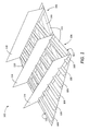
- FIGURE 1 a top perspective view of a structural joint 102 is shown.
- the structural joint 102 may include a first component 104 and a second component 106 being joined together.
- the structural joint 102 may include a side-of-body joint of an aircraft, with the first component 104 being a wing box of the aircraft and the second component 106 being a center box of the aircraft fuselage.
- An aircraft side-of-body joint is a location in which the aircraft wing is coupled to the fuselage. At this location, high loads are commonly present due to the various forces acting on an aircraft wing and fuselage during flight operations. Composite materials are often used on aircraft and other vehicle components.
- the side-of-body joint is a particularly challenging application for composite components due to the excessive forces present at the side-of-body joint and the corresponding risk of composite delamination and failure.
- utilizing composite materials at the side-of-body joint typically results in the wing box stringers, center box stringers, and aircraft skin to be terminated at one or more splice plates or fixtures to manage the associated loads.
- the embodiments described herein allow for the skin to be continuous over this joint from the wing box to the center box, without terminating at a splice plate. In doing so, the weight of the structural joint 102 may be decreased while maintaining the ability to adequately manage the loads experienced during flight operations.
- the various embodiments may be discussed with respect to the aircraft side-of-body joint example, the concepts and embodiments described herein may be equally applicable to any structural joint of any vehicle or fixed structure without departing from the scope of this disclosure and the accompanying claims.
- the structural joint 102 may include the first component 104 and the second component 106 being joined together.
- the first component 104 may include any number of inside blade stringers 108, one or more structural members 114 attached to the inside blade stringers 108 and/or the continuous skin 112, as well as the continuous skin 112.
- the second component 106 may include any number of outside blade stringers 110, one or more structural members 118 attached to the outside blade stringers 110 and/or the continuous skin 112, as well as the continuous skin 112.
- the first component 104 may include a wing box, which may include a number of ribs represented as the structural member 114, as well as any number and type of wing components that are not shown in FIGURE 1 , but are traditionally coupled to the ribs and/or stringers and skin associated with the aircraft wing.
- the second component 106 in the side-of-body example may include a center box of a fuselage, which may include a number of structural members 116, as well as any number and type of fuselage components that are not shown in FIGURE 1 , but are traditionally coupled to the stringers or skin associated with the aircraft fuselage.
- the inside blade stringers 108 are configured substantially parallel to one another and are each coupled to an inside surface 120 of the continuous skin 112, while the outside blade stringers 110 are also configured substantially parallel to one another and coupled to an outside surface 122 of the continuous skin 112.
- the broken lines shown in FIGURE 1 represent the outside blade stringers 110 coupled to the opposing side, or outside surface 122, of the continuous skin. As seen in FIGURE 1 , and as will be described in greater detail below with respect to FIGURE 5 , the ends of the inside blade stringers 108 and outside blade stringers 110 overlap one another on opposing sides of the continuous skin 112.
- a structural member 116 which may include a T-chord or first wing rib, may be coupled to the structural joint 102 at a central location where the first component 104 and second component 106 converge.
- the structural member 116 may provide support to restrain the structural joint 102 from moving out of plane.
- the structural members 114, 116, and 118 are only shown in FIGURE 1 for clarity purposes. It should be appreciated that the structural joint 102 shown in the various figures represents a partial structure and is not drawn to scale.
- the structural joint 102 may be any shape and size, with inside blade stringers 108, outside blade stringers 110, and continuous skin 112 having any dimensions.
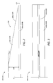
- FIGURES 2 and 3 show side and top views, respectively, of a joint end 202 of a partial inside blade stringer 108 or outside blade stringer 110 according to one embodiment.
- the inside blade stringers 108 each include an inside stringer base flange 204A that is bonded or otherwise coupled to an inside surface 120 of the continuous skin 112.
- An inside stringer web 206A projects from the inside stringer base flange 204A to a height 210 at an open edge 208A opposite the inside stringer base flange 204A.
- the outside blade stringers 110 each include an outside stringer base flange 204B that is bonded or otherwise coupled to an outside surface 122 of the continuous skin 112.
- An outside stringer web 206B projects from the outside stringer base flange 204B to a height 210 at an open edge 208B ("208A" and "208B” generally referred to herein as "208") opposite the outside stringer base flange 204B.
- open edge refers to an edge that is not coupled to or abutting a top cap or top flange as is typical with conventional "I-beam" stringer configurations.
- the open edge 208 is possible due to the additional strength and other structural advantages provided by the overlap and/or overlap location of the inside blade stringers 108 and the outside blade stringers 110.
- the open edge 208 may be replaced by an edge that abuts, continues into, or is coupled to a top cap or top flange in the manner of conventional stringers.
- the open edge 208 may reduce the manufacturing costs and reduce the overall weight of the structural joint 102 and corresponding components as compared to traditional stringer designs.
- the inside stringer web 206A is trimmed, or tapers, from the height 210 to a reduced height 212 at the joint end 202 of the stringer. Any reduction in strength of the stringer due to the tapering may be offset by the corresponding overlapping stringers on the opposite side of the continuous skin 112.
- the inside stringer webs 206A of the inside blade stringers 108 may be at full height, or height 210, providing maximum structural reinforcement and stiffening advantages. As the inside blade stringers 108 extend to through the structural member 114, they begin to overlap the outboard ends of the outside blade stringers 110 on the outside surface 122 of the continuous skin 112.
- the inside stringer webs 206A begin to taper until they reach the reduced height 212 at the outboard ends of the stringers.
- the outside stringer webs 206B of the outside blade stringers 110 correspondingly taper to the reduced height 212 starting approximately where the overlapping of the inside blade stringers 108 begins, which may be approximately at the structural member 118 in this example.
- inside stringer webs 206A and the outside stringer webs 206B taper, they may lose a portion of the structural reinforcement and stiffness characteristics that are present when the open edges 208A and 208B are positioned at the height 210 from the inside stringer base flanges 204A and outside stringer base flanges 204B, respectively. However, these losses are offset by the addition of the corresponding overlapping stringer on the opposing side of the continuous skin 112.
- the first component 104 may be coupled with the second component 106 at the structural joint 102 with the use of continuous skin 112, the inside blade stringers 108, and the outside blade stringers 110, without the use of complex and heavy splice plates.
- the height 210 of the inside stringer webs 206A and of the outside stringer webs 206B may depend upon the particular application for which the stringers are designed and the corresponding loads for which the stringers and structural joint 102 will be subjected to.
- Other dimensions related to the inside blade stringers 108 and outside blade stringers 110 including but not limited to the width and thicknesses of the inside stringer base flange 204A and of the outside stringer base flange 204B, and the thickness of the stringer webs, are also application specific.
- the reduced height 212 may also depend upon the particular application for the inside blade stringers 108 and outside blade stringers 110.
- the reduced height is approximately zero so that the inside stringer webs 206A and outside stringer webs 206B taper from the height 210 to a reduced height 212 that is approximately flush an outer surface of the inside stringer base flange 204A and an outer surface of the outside stringer base flange 204B, respectively.
- the tapering characteristics may also vary according to the specific application.
- the tapering angle 214 in which the open edge 208 tapers downward from horizontal may depend, among other design criteria, on the desired overlap area of the structural joint 102 as will be discussed in greater detail below with respect to FIGURE 5 .
- the height 210 of the inside blade stringers 108 and outside blade stringers 110 may be between 2.5-3 inches, tapering down to a reduced height 212 of 0 inches at the termination point of the stringers, which may be between 55-65 inches from the point at which the tapering begins. In doing so, the tapering angle 214 may be approximately 2.75 degrees, or between 2.5-3 degrees.
- the inside blade stringers 108 may begin at section 12 of the aircraft wing and traverse the wing until terminating at section 11 close or within the wing box.
- the outside blade stringers 110 may begin within the center box of the aircraft fuselage and end at or near the second rib of the wing. It should be understood that these examples are provided for illustrative purposes only and that the actual characteristics of the inside blade stringers 108 and the outside blade stringers 110 may vary depending on the particular implementation.
- the inside blade stringers 108 and outside blade stringers 110 may be made of any appropriate materials depending on the particular application and the loads in which the structural joint 102 is to be subjected.
- the inside blade stringers 108 and outside blade stringers 110, as well as the continuous skin 112 may be manufactured from composite materials, such as composite materials having a high axial modulus for increased stiffness.
- Composite materials commonly provide high strength characteristics with a significant weight savings as compared to conventional metallic materials.
- the overlapping inside/outside stringer configuration of the structural joint 102 described herein allows for the use of continuous skin 112 across the joint without the risk of delamination or failure, and without the use of heavy and complex splice plates.
- FIGURE 4 shows a bottom perspective view of the structural joint 102 of FIGURE 1 according to one embodiment.
- the structural members 114, 116, and 118 have been omitted for clarity.
- the outside blade stringers 110 are arranged substantially parallel to one another and extend into the structural joint 102 from the second component 106.
- the outside stringer base flanges 204B are bonded or otherwise coupled to the outside surface 122 of the continuous skin 112.
- the outside stringer webs 206B taper from the height 210 to the reduced height 212 at the outboard ends of the stringers.
- the outside blade stringers 110 and the inside blade stringers 108 overlap on opposing sides of the structural joint 102.
- the inside blade stringers 108 extend from the first component 104 into the structural joint 102.
- the inside blade stringers 108 may extend from a wing tip of an aircraft wing into a side-of-body joint, which is represented as the structural joint 102.
- the outside blade stringers 110 extend from the second component 106, such as a center box of an aircraft fuselage, into the structural joint 102.
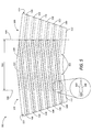
- the inside blade stringers 108 are coupled to the inside surface 120 of the continuous skin 112, while the outside blade stringers 110 are coupled to the outside surface 122 of the continuous skin 112 as depicted by the broken lines.
- the inside blade stringers 108 and the outside blade stringers 110 overlap on opposing sides of the continuous skin 112 within an overlap area 502, beginning at overlap locations 506.
- the specific size and shape of the overlap area 502 may depend on the specific application for the structural joint 102.
- the ends of the inside blade stringers 108 and outside blade stringers 110 may vary in length and termination location so that they may or may not align as shown in FIGURE 5 .
- the inside blade stringers 108 and outside blade stringers 110 overlap on opposing sides of the continuous skin 112 according to an overlap angle 504 with respect to one another.
- the enlargement shown in FIGURE 5 highlights the overlap angle 504. By overlapping at an angle, the stiffness provided by the inside blade stringers 108 and outside blade stringers 110 at the structural joint 102 is increased.
- the overlap angle 504 is a non-zero overlap angle that is approximately equivalent to the sweep angle of an aircraft wing with respect to the fuselage.
- the inside blade stringers 108 extend through the aircraft wing and intersect the fuselage at the side-of-body joint, or structural joint 102.
- the outside blade stringers 110 may be positioned parallel to a lateral or pitch axis of the aircraft so that the overlap angle 504 corresponds to the sweep angle of the aircraft wings.
- This overlap angle 504, or sweep angle according to the given example embodiment may be between 30 to 50 degrees depending on the dihedral angle and wing span, among other aircraft variables.
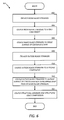
- FIGURE 6 an illustrative routine 600 for creating a structural joint utilizing inside blade stringers 108, outside blade stringers 110, and continuous skin 112 will now be described in detail. It should be appreciated that more or fewer operations may be performed than shown in the figures and described herein. These operations may also be performed in a different order than those described herein.
- the routine 600 begins at operation 602, where the inside blade stringers 108 are provided.
- the inside blade stringers 108 may each include an inside stringer base flange 204A and an inside stringer web 206A projecting upwards from the flange to an open edge 208 positioned a height 210 from the flange.
- the inside stringer web 206A tapers from the height 210 to a reduced height 212 according to a tapering angle 214 as described above.
- the routine 600 continues to operation 604, where the inside blade stringers 108 are coupled to a first component 104.
- the first component 104 may include any number and type of systems or devices that define the first component 104 being joined with the second component 106 at the structural joint 102.
- the first component 104 may include aircraft ribs, spars, flight control and fuel systems, and the like.
- the structural member 114 shown in FIGURE 1 and described above may represent an aircraft rib or other partial or entire portion of the first component 104.
- the routine 600 continues from operation 604 to operation 606, where the inside blade stringers 108 are coupled to the continuous skin 112.
- the inside stringer base flanges 204A are bonded or otherwise coupled to the inside surface 120 of the continuous skin 112 so that the joint ends 202 of the stringers terminate in the desired locations within the overlap area 502.
- the routine 600 continues to operation 608, where the outside blade stringers 110 are provided.
- the operations described herein may occur in a different order or simultaneously without departing from the scope of this disclosure.
- the outside blade stringers 110 and inside blade stringers 108 may be provided and coupled to the continuous skin 112 substantially simultaneously. However, for clarity, these operations are described sequentially.
- the outside blade stringers 110 may each include an outside stringer base flange 204B and an outside stringer web 206B projecting upwards from the flange to an open edge 208 positioned a height 210 from the flange.
- the outside stringer web 206B tapers from the height 210 to a reduced height 212 according to a tapering angle 214.
- the routine 600 continues to operation 610, where the outside blade stringers 110 are coupled to the second component 106.
- the second component 106 may include any number and type of systems or devices that define the second component 106 being joined with the first component 104 at the structural joint 102.
- the second component 106 may include fuselage spars, longerons, flight control and fuel systems, and the like.
- the structural member 118 shown in FIGURE 1 and described above may represent center box component or other partial or entire portion of the second component 106.
- the routine 600 continues from operation 610 to operation 612, where the outside blade stringers 110 are coupled to the continuous skin 112.
- the outside stringer base flanges 204B are bonded or otherwise coupled to the outside surface 122 of the continuous skin 112 so that the joint ends 202 of the stringers terminate in the desired locations within the overlap area 502.
- the routine continues to operation 614, where any additional structural members may be coupled to the appropriate structural joint components, and the routine 600 ends.
- the T-chord which is represented in FIGURE 1 as the structural member 116, may be bonded or mechanically fastened to the inside blade stringers 108, the outside blade stringers 110, and the continuous skin 112 to provide the structural joint 102 with the desired additional stiffness and strength characteristics.
- a structural joint comprising: a continuous skin 112 having an inside surface and an outside surface; a plurality of inside blade stringers 108 coupled to the inside surface of the continuous skin 112 and configured substantially parallel to one another, each inside blade stringer 108 having a joint end 202; and a plurality of outside blade stringers 110 coupled to the outside surface of the continuous skin 112 and configured substantially parallel to one another, each outside blade stringer 110 having a joint end 202, wherein the joint ends 202 of the plurality of inside blade stringers 108 and of the plurality of outside blade stringers 110 overlap on opposing sides of the continuous skin 112.
- each inside blade stringer 108 includes an inside stringer base flange 204A coupled to the inside surface of the continuous skin 112 and an inside stringer web 206A projecting away from the inside stringer base flange 204A and tapering to a reduced height at the joint end 202 of the inside blade stringer
- each outside blade stringer 110 includes an outside stringer base flange 204B coupled to the outside surface of the continuous skin 112 and an outside stringer web 206B projecting away from the outside stringer base flange 204B and tapering to a reduced height at the joint end 202 of the outside blade stringer.
- the inside stringer web 206A includes an open edge opposite the inside stringer base flange 204A that tapers to the reduced height at the joint end 202 of the inside blade stringer 108
- the outside stringer web 206B comprises an open edge opposite the outside stringer base flange 204B that tapers to the reduced height at the joint end 202 of the outside blade stringer 110
- the reduced height includes a height flush with an outer surface of the inside stringer web 206A or of the outside stringer web 206B.
- the joint ends 202 of the plurality of inside blade stringers 108 and of the plurality of outside blade stringers 110 overlap on opposing sides of the continuous skin 112 according to a non-zero overlap angle.
- the non-zero overlap angle includes a sweep angle of an aircraft wing.
- the structural joint 102 includes an aircraft side-of-body joint joining a wing box and a center box.
- the structural joint 102 of claim 1, further includes a structural member 114, 116, 118 coupled to the plurality of inside blade stringers 108, the plurality of outside blade stringers 110, and the continuous skin 112.
- each inside stringer web 206A begins tapering to a reduced height at approximately an overlap location where the inside stringer begins overlapping an outside blade stringer 110
- each outside stringer web 206B begins tapering to the reduced height at approximately an overlap location where the outside stringer begins overlapping an inside blade stringer.
- a method is disclosed of joining two structures, the method including: providing a plurality of inside blade stringers 108, each of the plurality of inside blade stringers 108 comprising an inside stringer base flange 204A and an inside stringer web 206A projecting away from the inside stringer base flange 204A and tapering to a reduced height at a joint end 202 of the inside blade stringer 108, coupling the plurality of inside blade stringers 108 to a first structure; coupling the inside stringer base flange 204A of each of the plurality of inside blade stringers 108 to an inside surface of a continuous skin 112; providing a plurality of outside blade stringers 110, each of the plurality of outside blade stringers 110 including an outside stringer base flange and an outside stringer web 206B projecting away from the outside stringer base flange 204B and tapering to a reduced height at a joint end 202 of the outside blade stringer 110; coupling the plurality of outside blade stringers 110 to a second
- providing the plurality of inside blade stringers 108 further includes providing the plurality of inside blade stringers 108, each having an inside stringer web 206A with an open edge opposite the inside stringer base flange 204A that tapers to the reduced height at the joint end of the inside blade stringer 108
- providing the plurality of outside blade stringers 110 further comprises providing the plurality of outside blade stringers 110, each having an outside stringer web 206B with an open edge opposite the outside stringer base flange 204B that tapers to the reduced height at the joint end 202 of the outside blade stringer 110.
- the reduced height includes a height flush with an outer surface of the inside stringer web 206A or of the outside stringer web 206B.
- the method includes coupling a structural member 114, 116, 118 to the plurality of inside blade stringers, the plurality of outside blade stringers 110, and the continuous skin 112.
- coupling the inside stringer base flange 204A of each of the plurality of inside blade stringers 108 to the inside surface of the continuous skin 112 and coupling the outside stringer base flange 204B of each of the plurality of outside blade stringers 110 to the outside surface of the continuous skin 112 includes coupling the plurality of inside blade stringers 108 and the plurality of outside blade stringers 110 to opposing surfaces of the continuous skin 112 at a non-zero overlap angle with respect to one another.
- non-zero overlap angle includes a sweep angle of an aircraft wing.
- coupling the plurality of inside blade stringers 108 to a first structure comprises coupling the plurality of inside blade stringers 108 to at least one component of an aircraft wing
- coupling the plurality of outside blade stringers 110 to a second structure comprises coupling the plurality of outside blade stringers 110 to at least one component of a center box of an aircraft.
- a structural joint including a continuous skin 112; a plurality of inside blade stringers 108 configured substantially parallel to one another, each inside blade stringer 108 including an inside stringer base flange 204A coupled to an inside surface of the continuous skin 112 and an inside stringer web 206A having an open edge spaced a distance from the inside stringer base flange 204A, the distance decreasing to a reduced height at a joint end 202 of the inside blade stringer 108; and a plurality of outside blade stringers 110 configured substantially parallel to one another, each outside blade stringer 110 including an outside stringer base flange 204B coupled to an outside surface of the continuous skin 112 and an outside stringer web 206B having an open edge spaced a distance from the outside stringer base flange 204B, the distance decreasing to a reduced height at a joint end 202 of the outside blade stringer 110, wherein the joint ends 202 of the plurality of inside blade stringers 108 and of the plurality of outside blade stringers 110 overlap on oppos
- the structural joint 102 includes an aircraft side-of-body joint that couples a wing box of an aircraft wing to a center box of an aircraft fuselage.
- the joint ends 202 of the plurality of inside blade stringers (108) and of the plurality of outside blade stringers 110 overlap on opposing sides of the continuous skin 112 according to a sweep angle of the aircraft wing.
- the structural joint 102 includes an aircraft rib coupled to the plurality of inside blade stringers 108, the plurality of outside blade stringers 110, and the continuous skin 112.
Landscapes
- Engineering & Computer Science (AREA)
- Mechanical Engineering (AREA)
- Aviation & Aerospace Engineering (AREA)
- Moulding By Coating Moulds (AREA)
- Connection Of Plates (AREA)
- Bridges Or Land Bridges (AREA)
- Turbine Rotor Nozzle Sealing (AREA)
Abstract
Description
- Aircraft, as well as other types vehicles and structures, utilize stringers to provide strength and stiffening characteristics to skin that covers various surfaces of the aircraft or structure. As two components converge at a joint, conventional techniques include terminating the stringers from each component and skin at one or more metallic splice plates that provide the desired reinforcement to the joint. When utilizing composite materials for the stringers and skin, the potential for delamination exists at these joints where increased loads and corresponding moments are common. To accommodate excessive forces at these joints and prevent delamination and composite failure, these conventional joints and associated splice plates are commonly complex and undesirably heavy.
- It is with respect to these considerations and others that the disclosure made herein is presented.
- It should be appreciated that this Summary is provided to introduce a selection of concepts in a simplified form that are further described below in the Detailed Description. This Summary is not intended to be used to limit the scope of the claimed subj ect matter.
- Apparatus and methods provide for a structural joint coupling two components with a continuous skin and overlapping inside and outsides stringers. According to one aspect of the disclosure provided herein, a structural joint may include a continuous skin with an inside and an outside surface. A number of inside blade stringers may be coupled to the inside surface of the continuous skin and positioned parallel to each other. A number of outside blade stringers may be coupled to the outside surface of the continuous skin and positioned parallel to one another. The inside and outside stringers may have joint ends that overlap on opposing sides of the continuous skin.
- According to another aspect, a method for joining two structures may include providing a number of inside blade stringers, each having an inside stringer base flange and an inside stringer web projecting away from the inside stringer base flange and tapering to a reduced height at a joint end of the stringer. The inside blade stringers are coupled to a first structure. The inside stringer base flange of each inside blade stringer is coupled to an inside surface of a continuous skin. A number of outside blade stringers may be provided, each of which may include an outside stringer base flange and an outside stringer web projecting away from the outside stringer base flange and tapering to a reduced height at a joint end of the outside blade stringer. The outside blade stringers may be coupled to a second structure being joined to the first structure. The outside stringer base flange of each outside blade stringer may be coupled to an outside surface of the continuous skin. The joint ends of each inside and outside blade stringer may overlap on opposing sides of the continuous skin.
- According to yet another aspect, a structural joint may include a continuous skin, a number of inside blade stringers, and a number of outside blade stringers. The inside blade stringers may be positioned parallel to one another and may each include an inside stringer base flange coupled to an inside surface of the continuous skin and an inside stringer web having an open edge spaced a distance from the inside stringer base flange. This distance may decrease to a reduced height at a joint end of each inside blade stringer. The outside blade stringers may similarly be positioned parallel to one another and may each include an outside stringer base flange coupled to an outside surface of the continuous skin and an outside stringer web having an open edge spaced a distance from the outside stringer base flange. This distance may decrease to a reduced height at a joint end of each outside blade stringer. The joint ends of the inside blade stringers and the outside blade stringers may overlap on opposing sides of the continuous skin.
- The features, functions, and advantages that have been discussed can be achieved independently in various embodiments of the present disclosure or may be combined in yet other embodiments, further details of which can be seen with reference to the following description and drawings.
-
-
FIGURE 1 is a top perspective view of an example of a side-of-body joint utilizing inside blade stringers and outside blade stringers according to various embodiments presented herein; -
FIGURE 2 is a side view of a joint end of an example blade stringer according to various embodiments presented herein; -
FIGURE 3 is a top view of a joint end of an example blade stringer according to various embodiments presented herein; -
FIGURE 4 is a bottom perspective view of an example of a side-of-body joint utilizing inside blade stringers and outside blade stringers according to various embodiments presented herein; -
FIGURE 5 is a top view of an example of a side-of-body joint utilizing inside blade stringers and outside blade stringers with an enlargement illustrating an overlap angle according to various embodiments presented herein; and -
FIGURE 6 is a process flow diagram illustrating a method for creating a structural joint utilizing inside blade stringers, outside blade stringers, and continuous skin according to various embodiments presented herein. - The following detailed description is directed to methods for providing a continuous skin at a structural joint using inside and outside blade stringers. As discussed briefly above, conventional component stringers and corresponding skin terminate at a joint, which requires the use of reinforced termination blocks or fittings in order to prevent composite delamination or failure at high-load areas. The result is a complex structural joint that increases the weight of the structure. This complexity and weight is undesirable when used in conjunction with an aircraft or other vehicle.
- Utilizing the concepts described herein, structural components, such as an aircraft wing and fuselage, may be joined together in a manner that allows the composite or other skin to be continuous over the two components being joined without the risk of delamination or load failure. As will be described in detail below, blade stringers may be used on the inside and outside surfaces of the continuous skin. Rather than a traditional "I-beam" stringer configuration that includes a base flange, web, and top cap, the blade stringers described herein may be configured with a base flange and web, without the use of a top cap that is common with traditional stringers, which further reduces the weight and complexity of the components. The webs of the stringers described below may taper downward toward the base flanges towards the ends of the stringers where the components are being joined. The webs may taper within the overlapping area in which the inside and outside stringers overlap on opposing sides of the continuous skin.
- In the following detailed description, references are made to the accompanying drawings that form a part hereof, and which are shown by way of illustration, specific embodiments, or examples. Referring now to the drawings, in which like numerals represent like elements through the several figures, the structural joint having a continuous skin with inside and outside blade stringers will be described. Turning to
FIGURE 1 a top perspective view of astructural joint 102 is shown. Thestructural joint 102 may include afirst component 104 and asecond component 106 being joined together. - According to one illustrative embodiment, the
structural joint 102 may include a side-of-body joint of an aircraft, with thefirst component 104 being a wing box of the aircraft and thesecond component 106 being a center box of the aircraft fuselage. An aircraft side-of-body joint is a location in which the aircraft wing is coupled to the fuselage. At this location, high loads are commonly present due to the various forces acting on an aircraft wing and fuselage during flight operations. Composite materials are often used on aircraft and other vehicle components. The side-of-body joint is a particularly challenging application for composite components due to the excessive forces present at the side-of-body joint and the corresponding risk of composite delamination and failure. - As previously discussed, utilizing composite materials at the side-of-body joint typically results in the wing box stringers, center box stringers, and aircraft skin to be terminated at one or more splice plates or fixtures to manage the associated loads. However, the embodiments described herein allow for the skin to be continuous over this joint from the wing box to the center box, without terminating at a splice plate. In doing so, the weight of the
structural joint 102 may be decreased while maintaining the ability to adequately manage the loads experienced during flight operations. Although the various embodiments may be discussed with respect to the aircraft side-of-body joint example, the concepts and embodiments described herein may be equally applicable to any structural joint of any vehicle or fixed structure without departing from the scope of this disclosure and the accompanying claims. - As previously stated, the
structural joint 102 may include thefirst component 104 and thesecond component 106 being joined together. According to one embodiment, thefirst component 104 may include any number ofinside blade stringers 108, one or morestructural members 114 attached to theinside blade stringers 108 and/or thecontinuous skin 112, as well as thecontinuous skin 112. Similarly, thesecond component 106 may include any number ofoutside blade stringers 110, one or morestructural members 118 attached to theoutside blade stringers 110 and/or thecontinuous skin 112, as well as thecontinuous skin 112. Continuing the side-of-body example given above, thefirst component 104 may include a wing box, which may include a number of ribs represented as thestructural member 114, as well as any number and type of wing components that are not shown inFIGURE 1 , but are traditionally coupled to the ribs and/or stringers and skin associated with the aircraft wing. Thesecond component 106 in the side-of-body example may include a center box of a fuselage, which may include a number ofstructural members 116, as well as any number and type of fuselage components that are not shown inFIGURE 1 , but are traditionally coupled to the stringers or skin associated with the aircraft fuselage. - According to one embodiment, the
inside blade stringers 108 are configured substantially parallel to one another and are each coupled to aninside surface 120 of thecontinuous skin 112, while theoutside blade stringers 110 are also configured substantially parallel to one another and coupled to anoutside surface 122 of thecontinuous skin 112. The broken lines shown inFIGURE 1 represent theoutside blade stringers 110 coupled to the opposing side, oroutside surface 122, of the continuous skin. As seen inFIGURE 1 , and as will be described in greater detail below with respect toFIGURE 5 , the ends of theinside blade stringers 108 andoutside blade stringers 110 overlap one another on opposing sides of thecontinuous skin 112. - A
structural member 116, which may include a T-chord or first wing rib, may be coupled to the structural joint 102 at a central location where thefirst component 104 andsecond component 106 converge. Thestructural member 116 may provide support to restrain the structural joint 102 from moving out of plane. Thestructural members FIGURE 1 for clarity purposes. It should be appreciated that the structural joint 102 shown in the various figures represents a partial structure and is not drawn to scale. The structural joint 102 may be any shape and size, withinside blade stringers 108, outsideblade stringers 110, andcontinuous skin 112 having any dimensions. -
FIGURES 2 and 3 show side and top views, respectively, of ajoint end 202 of a partialinside blade stringer 108 oroutside blade stringer 110 according to one embodiment. Theinside blade stringers 108 each include an insidestringer base flange 204A that is bonded or otherwise coupled to aninside surface 120 of thecontinuous skin 112. Aninside stringer web 206A projects from the insidestringer base flange 204A to aheight 210 at anopen edge 208A opposite the insidestringer base flange 204A. Similarly, theoutside blade stringers 110 each include an outsidestringer base flange 204B that is bonded or otherwise coupled to anoutside surface 122 of thecontinuous skin 112. Anoutside stringer web 206B projects from the outsidestringer base flange 204B to aheight 210 at anopen edge 208B ("208A" and "208B" generally referred to herein as "208") opposite the outsidestringer base flange 204B. - The term "open edge" as used herein refers to an edge that is not coupled to or abutting a top cap or top flange as is typical with conventional "I-beam" stringer configurations. According to various embodiments, the open edge 208 is possible due to the additional strength and other structural advantages provided by the overlap and/or overlap location of the
inside blade stringers 108 and theoutside blade stringers 110. According to alternative embodiments, the open edge 208 may be replaced by an edge that abuts, continues into, or is coupled to a top cap or top flange in the manner of conventional stringers. However, the open edge 208 may reduce the manufacturing costs and reduce the overall weight of the structural joint 102 and corresponding components as compared to traditional stringer designs. - According to one embodiment, the
inside stringer web 206A is trimmed, or tapers, from theheight 210 to a reducedheight 212 at thejoint end 202 of the stringer. Any reduction in strength of the stringer due to the tapering may be offset by the corresponding overlapping stringers on the opposite side of thecontinuous skin 112. For example, at a location on thefirst component 104 that is to the left of thestructural member 114 inFIGURE 1 , theinside stringer webs 206A of theinside blade stringers 108 may be at full height, orheight 210, providing maximum structural reinforcement and stiffening advantages. As theinside blade stringers 108 extend to through thestructural member 114, they begin to overlap the outboard ends of theoutside blade stringers 110 on theoutside surface 122 of thecontinuous skin 112. At approximately this position according to one embodiment, theinside stringer webs 206A begin to taper until they reach the reducedheight 212 at the outboard ends of the stringers. Theoutside stringer webs 206B of theoutside blade stringers 110 correspondingly taper to the reducedheight 212 starting approximately where the overlapping of theinside blade stringers 108 begins, which may be approximately at thestructural member 118 in this example. - As the
inside stringer webs 206A and theoutside stringer webs 206B taper, they may lose a portion of the structural reinforcement and stiffness characteristics that are present when theopen edges height 210 from the insidestringer base flanges 204A and outsidestringer base flanges 204B, respectively. However, these losses are offset by the addition of the corresponding overlapping stringer on the opposing side of thecontinuous skin 112. In other words, when theinside stringer webs 206A of theinside blade stringers 108 are at or near the reducedheight 212 at a location on theinside surface 120 of thecontinuous skin 112, the loads experienced by the structural joint 102 at that location remain controlled since theoutside stringer webs 206B of theoutside blade stringers 110 on theoutside surface 122 of thecontinuous skin 112 at that same location remain at or near theheight 210. Moreover, by tapering theinside stringer webs 206A and theoutside stringer webs 206B, the strain within the corresponding webs is reduced, which prevents delamination between theinside stringer webs 206A and insidestringer base flanges 204A, as well as between theoutside stringer webs 206B and outsidestringer base flanges 204B, that may occur as a result of this strain. In this manner, thefirst component 104 may be coupled with thesecond component 106 at the structural joint 102 with the use ofcontinuous skin 112, theinside blade stringers 108, and theoutside blade stringers 110, without the use of complex and heavy splice plates. - The
height 210 of theinside stringer webs 206A and of theoutside stringer webs 206B may depend upon the particular application for which the stringers are designed and the corresponding loads for which the stringers and structural joint 102 will be subjected to. Other dimensions related to theinside blade stringers 108 andoutside blade stringers 110, including but not limited to the width and thicknesses of the insidestringer base flange 204A and of the outsidestringer base flange 204B, and the thickness of the stringer webs, are also application specific. The reducedheight 212 may also depend upon the particular application for theinside blade stringers 108 andoutside blade stringers 110. According to one embodiment, the reduced height is approximately zero so that theinside stringer webs 206A andoutside stringer webs 206B taper from theheight 210 to a reducedheight 212 that is approximately flush an outer surface of the insidestringer base flange 204A and an outer surface of the outsidestringer base flange 204B, respectively. - It should be appreciated that the tapering characteristics may also vary according to the specific application. For example, the tapering
angle 214 in which the open edge 208 tapers downward from horizontal may depend, among other design criteria, on the desired overlap area of the structural joint 102 as will be discussed in greater detail below with respect toFIGURE 5 . According to one illustrative embodiment, theheight 210 of theinside blade stringers 108 andoutside blade stringers 110 may be between 2.5-3 inches, tapering down to a reducedheight 212 of 0 inches at the termination point of the stringers, which may be between 55-65 inches from the point at which the tapering begins. In doing so, the taperingangle 214 may be approximately 2.75 degrees, or between 2.5-3 degrees. - According to one embodiment in which the structural joint 102 includes an aircraft side-of-body joint, the
inside blade stringers 108 may begin at section 12 of the aircraft wing and traverse the wing until terminating at section 11 close or within the wing box. Similarly, theoutside blade stringers 110 may begin within the center box of the aircraft fuselage and end at or near the second rib of the wing. It should be understood that these examples are provided for illustrative purposes only and that the actual characteristics of theinside blade stringers 108 and theoutside blade stringers 110 may vary depending on the particular implementation. - The
inside blade stringers 108 andoutside blade stringers 110 may be made of any appropriate materials depending on the particular application and the loads in which the structural joint 102 is to be subjected. According to various embodiments, theinside blade stringers 108 andoutside blade stringers 110, as well as thecontinuous skin 112, may be manufactured from composite materials, such as composite materials having a high axial modulus for increased stiffness. Composite materials commonly provide high strength characteristics with a significant weight savings as compared to conventional metallic materials. As discussed above, the overlapping inside/outside stringer configuration of the structural joint 102 described herein allows for the use ofcontinuous skin 112 across the joint without the risk of delamination or failure, and without the use of heavy and complex splice plates. -
FIGURE 4 shows a bottom perspective view of thestructural joint 102 ofFIGURE 1 according to one embodiment. Thestructural members outside blade stringers 110 are arranged substantially parallel to one another and extend into the structural joint 102 from thesecond component 106. The outsidestringer base flanges 204B are bonded or otherwise coupled to theoutside surface 122 of thecontinuous skin 112. Theoutside stringer webs 206B taper from theheight 210 to the reducedheight 212 at the outboard ends of the stringers. As seen from the broken lines representing theinside blade stringers 108 coupled to theinside surface 120 of thecontinuous skin 112, theoutside blade stringers 110 and theinside blade stringers 108 overlap on opposing sides of thestructural joint 102. - Referring now to
FIGURE 5 , further aspects of the structural joint 102 will be described while referencing a top view of the example joint. The top view clearly illustrates one example of the overlap between theinside blade stringers 108 of thefirst component 104 and theoutside blade stringers 110 of thesecond component 106. According to this example embodiment, theinside blade stringers 108 extend from thefirst component 104 into thestructural joint 102. As an example, theinside blade stringers 108 may extend from a wing tip of an aircraft wing into a side-of-body joint, which is represented as thestructural joint 102. Theoutside blade stringers 110 extend from thesecond component 106, such as a center box of an aircraft fuselage, into thestructural joint 102. Theinside blade stringers 108 are coupled to theinside surface 120 of thecontinuous skin 112, while theoutside blade stringers 110 are coupled to theoutside surface 122 of thecontinuous skin 112 as depicted by the broken lines. - The
inside blade stringers 108 and theoutside blade stringers 110 overlap on opposing sides of thecontinuous skin 112 within anoverlap area 502, beginning atoverlap locations 506. The specific size and shape of theoverlap area 502 may depend on the specific application for thestructural joint 102. For example, the ends of theinside blade stringers 108 andoutside blade stringers 110 may vary in length and termination location so that they may or may not align as shown inFIGURE 5 . According to various embodiments, theinside blade stringers 108 andoutside blade stringers 110 overlap on opposing sides of thecontinuous skin 112 according to anoverlap angle 504 with respect to one another. The enlargement shown inFIGURE 5 highlights theoverlap angle 504. By overlapping at an angle, the stiffness provided by theinside blade stringers 108 andoutside blade stringers 110 at the structural joint 102 is increased. - According to one embodiment, the
overlap angle 504 is a non-zero overlap angle that is approximately equivalent to the sweep angle of an aircraft wing with respect to the fuselage. In this example, theinside blade stringers 108 extend through the aircraft wing and intersect the fuselage at the side-of-body joint, or structural joint 102. Theoutside blade stringers 110 may be positioned parallel to a lateral or pitch axis of the aircraft so that theoverlap angle 504 corresponds to the sweep angle of the aircraft wings. Thisoverlap angle 504, or sweep angle according to the given example embodiment, may be between 30 to 50 degrees depending on the dihedral angle and wing span, among other aircraft variables. - Turning now to
FIGURE 6 , anillustrative routine 600 for creating a structural joint utilizing insideblade stringers 108, outsideblade stringers 110, andcontinuous skin 112 will now be described in detail. It should be appreciated that more or fewer operations may be performed than shown in the figures and described herein. These operations may also be performed in a different order than those described herein. - The routine 600 begins at
operation 602, where theinside blade stringers 108 are provided. As described above, the number and configuration of theinside blade stringers 108 may depend upon the specific application for which the structural joint 102 is to be used. Theinside blade stringers 108 may each include an insidestringer base flange 204A and aninside stringer web 206A projecting upwards from the flange to an open edge 208 positioned aheight 210 from the flange. At the desired location, such as at a location along eachinside blade stringer 108 in which the stringer extends into theoverlap area 502 proximate to thejoint end 202 of the stringer, theinside stringer web 206A tapers from theheight 210 to a reducedheight 212 according to atapering angle 214 as described above. - From
operation 602, the routine 600 continues tooperation 604, where theinside blade stringers 108 are coupled to afirst component 104. Thefirst component 104 may include any number and type of systems or devices that define thefirst component 104 being joined with thesecond component 106 at thestructural joint 102. For example, thefirst component 104 may include aircraft ribs, spars, flight control and fuel systems, and the like. Thestructural member 114 shown inFIGURE 1 and described above may represent an aircraft rib or other partial or entire portion of thefirst component 104. - The routine 600 continues from
operation 604 tooperation 606, where theinside blade stringers 108 are coupled to thecontinuous skin 112. According to one embodiment, the insidestringer base flanges 204A are bonded or otherwise coupled to theinside surface 120 of thecontinuous skin 112 so that the joint ends 202 of the stringers terminate in the desired locations within theoverlap area 502. Fromoperation 606, the routine 600 continues tooperation 608, where theoutside blade stringers 110 are provided. It should again be appreciated that the operations described herein may occur in a different order or simultaneously without departing from the scope of this disclosure. For example, theoutside blade stringers 110 and insideblade stringers 108 may be provided and coupled to thecontinuous skin 112 substantially simultaneously. However, for clarity, these operations are described sequentially. - As described above, the number and configuration of the
outside blade stringers 110 may depend upon the specific application for which the structural joint 102 is to be used. Theoutside blade stringers 110 may each include an outsidestringer base flange 204B and anoutside stringer web 206B projecting upwards from the flange to an open edge 208 positioned aheight 210 from the flange. At the desired location, such as at a location along eachoutside blade stringer 110 in which the stringer extends into theoverlap area 502 proximate to thejoint end 202 of the stringer, theoutside stringer web 206B tapers from theheight 210 to a reducedheight 212 according to atapering angle 214. - From
operation 608, the routine 600 continues tooperation 610, where theoutside blade stringers 110 are coupled to thesecond component 106. As stated above with respect to thefirst component 104, thesecond component 106 may include any number and type of systems or devices that define thesecond component 106 being joined with thefirst component 104 at thestructural joint 102. For example, thesecond component 106 may include fuselage spars, longerons, flight control and fuel systems, and the like. Thestructural member 118 shown inFIGURE 1 and described above may represent center box component or other partial or entire portion of thesecond component 106. - The routine 600 continues from
operation 610 tooperation 612, where theoutside blade stringers 110 are coupled to thecontinuous skin 112. According to one embodiment, the outsidestringer base flanges 204B are bonded or otherwise coupled to theoutside surface 122 of thecontinuous skin 112 so that the joint ends 202 of the stringers terminate in the desired locations within theoverlap area 502. Fromoperation 612, the routine continues tooperation 614, where any additional structural members may be coupled to the appropriate structural joint components, and the routine 600 ends. For example, according to one embodiment, the T-chord, which is represented inFIGURE 1 as thestructural member 116, may be bonded or mechanically fastened to theinside blade stringers 108, theoutside blade stringers 110, and thecontinuous skin 112 to provide the structural joint 102 with the desired additional stiffness and strength characteristics. - In the figures and the test, a structural joint, comprising: a
continuous skin 112 having an inside surface and an outside surface; a plurality ofinside blade stringers 108 coupled to the inside surface of thecontinuous skin 112 and configured substantially parallel to one another, eachinside blade stringer 108 having ajoint end 202; and a plurality ofoutside blade stringers 110 coupled to the outside surface of thecontinuous skin 112 and configured substantially parallel to one another, eachoutside blade stringer 110 having ajoint end 202, wherein the joint ends 202 of the plurality ofinside blade stringers 108 and of the plurality ofoutside blade stringers 110 overlap on opposing sides of thecontinuous skin 112. In one variant, wherein eachinside blade stringer 108 includes an insidestringer base flange 204A coupled to the inside surface of thecontinuous skin 112 and aninside stringer web 206A projecting away from the insidestringer base flange 204A and tapering to a reduced height at thejoint end 202 of the inside blade stringer, and wherein eachoutside blade stringer 110 includes an outsidestringer base flange 204B coupled to the outside surface of thecontinuous skin 112 and anoutside stringer web 206B projecting away from the outsidestringer base flange 204B and tapering to a reduced height at thejoint end 202 of the outside blade stringer. - In yet still another variant, wherein the
inside stringer web 206A includes an open edge opposite the insidestringer base flange 204A that tapers to the reduced height at thejoint end 202 of theinside blade stringer 108, and wherein theoutside stringer web 206B comprises an open edge opposite the outsidestringer base flange 204B that tapers to the reduced height at thejoint end 202 of theoutside blade stringer 110. In yet another variant, the reduced height includes a height flush with an outer surface of theinside stringer web 206A or of theoutside stringer web 206B. - In one alternative, wherein the joint ends 202 of the plurality of
inside blade stringers 108 and of the plurality ofoutside blade stringers 110 overlap on opposing sides of thecontinuous skin 112 according to a non-zero overlap angle. In another alternative, the non-zero overlap angle includes a sweep angle of an aircraft wing. In yet another variant, the structural joint 102 includes an aircraft side-of-body joint joining a wing box and a center box. In yet another alternative, thestructural joint 102 of claim 1, further includes astructural member inside blade stringers 108, the plurality ofoutside blade stringers 110, and thecontinuous skin 112. In yet another alternative, wherein eachinside stringer web 206A begins tapering to a reduced height at approximately an overlap location where the inside stringer begins overlapping anoutside blade stringer 110, and wherein eachoutside stringer web 206B begins tapering to the reduced height at approximately an overlap location where the outside stringer begins overlapping an inside blade stringer. - In yet another variant, a method is disclosed of joining two structures, the method including: providing a plurality of
inside blade stringers 108, each of the plurality ofinside blade stringers 108 comprising an insidestringer base flange 204A and aninside stringer web 206A projecting away from the insidestringer base flange 204A and tapering to a reduced height at ajoint end 202 of theinside blade stringer 108, coupling the plurality ofinside blade stringers 108 to a first structure; coupling the insidestringer base flange 204A of each of the plurality ofinside blade stringers 108 to an inside surface of acontinuous skin 112; providing a plurality ofoutside blade stringers 110, each of the plurality ofoutside blade stringers 110 including an outside stringer base flange and anoutside stringer web 206B projecting away from the outsidestringer base flange 204B and tapering to a reduced height at ajoint end 202 of theoutside blade stringer 110; coupling the plurality ofoutside blade stringers 110 to a second structure; and coupling the outsidestringer base flange 204B of each of the plurality ofoutside blade stringers 110 to an outside surface of thecontinuous skin 112, wherein thejoint end 202 of eachinside blade stringer 108 overlaps thejoint end 202 of eachoutside blade stringer 110 on opposing sides of thecontinuous skin 112. In yet another variant, wherein providing the plurality ofinside blade stringers 108 further includes providing the plurality ofinside blade stringers 108, each having aninside stringer web 206A with an open edge opposite the insidestringer base flange 204A that tapers to the reduced height at the joint end of theinside blade stringer 108, and wherein providing the plurality ofoutside blade stringers 110 further comprises providing the plurality ofoutside blade stringers 110, each having anoutside stringer web 206B with an open edge opposite the outsidestringer base flange 204B that tapers to the reduced height at thejoint end 202 of theoutside blade stringer 110. In one alternative, the reduced height includes a height flush with an outer surface of theinside stringer web 206A or of theoutside stringer web 206B. In yet another alternative, the method includes coupling astructural member outside blade stringers 110, and thecontinuous skin 112. In another alternative, wherein coupling the insidestringer base flange 204A of each of the plurality ofinside blade stringers 108 to the inside surface of thecontinuous skin 112 and coupling the outsidestringer base flange 204B of each of the plurality ofoutside blade stringers 110 to the outside surface of thecontinuous skin 112 includes coupling the plurality ofinside blade stringers 108 and the plurality ofoutside blade stringers 110 to opposing surfaces of thecontinuous skin 112 at a non-zero overlap angle with respect to one another. In yet another alternative, wherein the non-zero overlap angle includes a sweep angle of an aircraft wing. In yet another variant, wherein coupling the plurality ofinside blade stringers 108 to a first structure comprises coupling the plurality ofinside blade stringers 108 to at least one component of an aircraft wing, and wherein coupling the plurality ofoutside blade stringers 110 to a second structure comprises coupling the plurality ofoutside blade stringers 110 to at least one component of a center box of an aircraft. - In yet another aspect, a structural joint is disclosed including a
continuous skin 112; a plurality ofinside blade stringers 108 configured substantially parallel to one another, eachinside blade stringer 108 including an insidestringer base flange 204A coupled to an inside surface of thecontinuous skin 112 and aninside stringer web 206A having an open edge spaced a distance from the insidestringer base flange 204A, the distance decreasing to a reduced height at ajoint end 202 of theinside blade stringer 108; and a plurality ofoutside blade stringers 110 configured substantially parallel to one another, eachoutside blade stringer 110 including an outsidestringer base flange 204B coupled to an outside surface of thecontinuous skin 112 and anoutside stringer web 206B having an open edge spaced a distance from the outsidestringer base flange 204B, the distance decreasing to a reduced height at ajoint end 202 of theoutside blade stringer 110, wherein the joint ends 202 of the plurality ofinside blade stringers 108 and of the plurality ofoutside blade stringers 110 overlap on opposing sides of thecontinuous skin 112. In one variant, wherein the structural joint 102 includes an aircraft side-of-body joint that couples a wing box of an aircraft wing to a center box of an aircraft fuselage. In another variant, the joint ends 202 of the plurality of inside blade stringers (108) and of the plurality ofoutside blade stringers 110 overlap on opposing sides of thecontinuous skin 112 according to a sweep angle of the aircraft wing. In still another variant, the structural joint 102 includes an aircraft rib coupled to the plurality ofinside blade stringers 108, the plurality ofoutside blade stringers 110, and thecontinuous skin 112. - Based on the foregoing, it should be appreciated that technologies for creating a structural joint utilizing overlapping inside and outside stringers with a continuous skin have been presented herein. The subject matter described above is provided by way of illustration only and should not be construed as limiting. Various modifications and changes may be made to the subject matter described herein without following the example embodiments and applications illustrated and described, and without departing from the true spirit and scope of the present disclosure, which is set forth in the following claims.
Claims (15)
- A structural joint, comprising:a continuous skin (112) having an inside surface and an outside surface;a plurality of inside blade stringers (108) coupled to the inside surface of the continuous skin (112) and configured substantially parallel to one another, each inside blade stringer (108) having a joint end (202); anda plurality of outside blade stringers (110) coupled to the outside surface of the continuous skin (112) and configured substantially parallel to one another, each outside blade stringer (110) having a joint end (202),wherein the joint ends (202) of the plurality of inside blade stringers (108) and of the plurality of outside blade stringers (110) overlap on opposing sides of the continuous skin (112).
- The structural joint (102) of claim 1,
wherein each inside blade stringer (108) comprises an inside stringer base flange (204A) coupled to the inside surface of the continuous skin (112) and an inside stringer web (206A) projecting away from the inside stringer base flange (204A) and tapering to a reduced height at the joint end (202) of the inside blade stringer, and
wherein each outside blade stringer (110) comprises an outside stringer base flange (204B) coupled to the outside surface of the continuous skin (112) and an outside stringer web (206B) projecting away from the outside stringer base flange (204B) and tapering to a reduced height at the joint end (202) of the outside blade stringer. - The structural joint (102) of claim 2, wherein the inside stringer web (206A) comprises an open edge opposite the inside stringer base flange (204A) that tapers to the reduced height at the joint end (202) of the inside blade stringer (108), and wherein the outside stringer web (206B) comprises an open edge opposite the outside stringer base flange (204B) that tapers to the reduced height at the joint end (202) of the outside blade stringer (110).
- The structural joint (102) of claim 2, wherein the reduced height comprises a height flush with an outer surface of the inside stringer web (206A) or of the outside stringer web (206B).
- The structural joint (102) of any of claims 1-4, wherein the joint ends (202) of the plurality of inside blade stringers (108) and of the plurality of outside blade stringers (110) overlap on opposing sides of the continuous skin (112) according to a non-zero overlap angle.
- The structural joint (102) of claim 5, wherein the non-zero overlap angle comprises a sweep angle of an aircraft wing.
- The structural joint (102) of any of claims 1-6, wherein the structural joint (102) comprises an aircraft side-of-body joint joining a wing box and a center box.
- The structural joint (102) of any of claims 1-7, further comprising a structural member (114, 116, 118) coupled to the plurality of inside blade stringers (108), the plurality of outside blade stringers (110), and the continuous skin (112).
- A method of joining two structures, the method comprising:providing a plurality of inside blade stringers (108), each of the plurality of inside blade stringers (108) comprising an inside stringer base flange (204A) and an inside stringer web (206A) projecting away from the inside stringer base flange (204A) and tapering to a reduced height at a joint end (202) of the inside blade stringer (108);coupling the plurality of inside blade stringers (108) to a first structure;coupling the inside stringer base flange (204A) of each of the plurality of inside blade stringers (108) to an inside surface of a continuous skin (112);providing a plurality of outside blade stringers (110), each of the plurality of outside blade stringers (110) comprising an outside stringer base flange and an outside stringer web (206B) projecting away from the outside stringer base flange (204B) and tapering to a reduced height at a joint end (202) of the outside blade stringer (110);coupling the plurality of outside blade stringers (110) to a second structure; andcoupling the outside stringer base flange (204B) of each of the plurality of outside blade stringers (110) to an outside surface of the continuous skin (112), wherein the joint end (202) of each inside blade stringer (108) overlaps the joint end (202) of each outside blade stringer (110) on opposing sides of the continuous skin (112).
- The method of claim 9, wherein providing the plurality of inside blade stringers (108) further comprises providing the plurality of inside blade stringers (108), each having an inside stringer web (206A) with an open edge opposite the inside stringer base flange (204A) that tapers to the reduced height at the joint end of the inside blade stringer (108), and wherein providing the plurality of outside blade stringers (110) further comprises providing the plurality of outside blade stringers (110), each having an outside stringer web (206B) with an open edge opposite the outside stringer base flange (204B) that tapers to the reduced height at the joint end (202) of the outside blade stringer (110).
- The method of claim 10, wherein the reduced height comprises a height flush with an outer surface of the inside stringer web (206A) or of the outside stringer web (206B).
- The method of any of claims 9-11, further comprising coupling a structural member (114, 116, 118) to the plurality of inside blade stringers, the plurality of outside blade stringers (110), and the continuous skin (112).
- The method of claim 9, wherein coupling the inside stringer base flange (204A) of each of the plurality of inside blade stringers (108) to the inside surface of the continuous skin (112) and coupling the outside stringer base flange (204B) of each of the plurality of outside blade stringers (110) to the outside surface of the continuous skin (112) comprises coupling the plurality of inside blade stringers (108) and the plurality of outside blade stringers (110) to opposing surfaces of the continuous skin (112) at a non-zero overlap angle with respect to one another.
- The method of claim 13, wherein the non-zero overlap angle comprises a sweep angle of an aircraft wing.
- The method of claim 9, wherein coupling the plurality of inside blade stringers (108) to a first structure comprises coupling the plurality of inside blade stringers (108) to at least one component of an aircraft wing, and wherein coupling the plurality of outside blade stringers (110) to a second structure comprises coupling the plurality of outside blade stringers (110) to at least one component of a center box of an aircraft.
Applications Claiming Priority (1)
| Application Number | Priority Date | Filing Date | Title |
|---|---|---|---|
| US13/367,782 US9010688B2 (en) | 2012-02-07 | 2012-02-07 | Structural joint having continuous skin with inside and outside stringers |
Publications (3)
| Publication Number | Publication Date |
|---|---|
| EP2626291A2 true EP2626291A2 (en) | 2013-08-14 |
| EP2626291A3 EP2626291A3 (en) | 2015-08-05 |
| EP2626291B1 EP2626291B1 (en) | 2018-12-05 |
Family
ID=47681762
Family Applications (1)
| Application Number | Title | Priority Date | Filing Date |
|---|---|---|---|
| EP13154237.5A Not-in-force EP2626291B1 (en) | 2012-02-07 | 2013-02-06 | Structural joint having continuous skin with inside and outside stringers |
Country Status (5)
| Country | Link |
|---|---|
| US (1) | US9010688B2 (en) |
| EP (1) | EP2626291B1 (en) |
| JP (1) | JP6118119B2 (en) |
| CN (1) | CN103241360B (en) |
| ES (1) | ES2714306T3 (en) |
Cited By (1)
| Publication number | Priority date | Publication date | Assignee | Title |
|---|---|---|---|---|
| US12162600B2 (en) | 2019-05-14 | 2024-12-10 | Airbus Operations Limited | Aircraft panel assembly |
Families Citing this family (4)
| Publication number | Priority date | Publication date | Assignee | Title |
|---|---|---|---|---|
| GB2528080A (en) * | 2014-07-08 | 2016-01-13 | Airbus Operations Ltd | Structure |
| US10850826B2 (en) * | 2017-03-24 | 2020-12-01 | The Boeing Company | Aircraft wing space frame |
| US11180238B2 (en) * | 2018-11-19 | 2021-11-23 | The Boeing Company | Shear ties for aircraft wing |
| CN113525523B (en) * | 2021-07-22 | 2022-12-13 | 哈尔滨工程大学 | Whale-simulated fluid anti-drag noise-reduction skin based on flexible joint vibration-reduction unit lattice structure |
Family Cites Families (17)
| Publication number | Priority date | Publication date | Assignee | Title |
|---|---|---|---|---|
| US4828202A (en) * | 1979-09-27 | 1989-05-09 | The Boeing Company | Method and apparatus for wideband vibration damping of reinforced skin structures |
| US4416349A (en) * | 1981-09-30 | 1983-11-22 | The Boeing Company | Viscoelastically damped reinforced skin structures |
| FR2649665B1 (en) * | 1989-07-12 | 1991-11-08 | Airbus Ind | LARGE CAPACITY FUSELAGE FOR AIRCRAFT |
| US5242523A (en) * | 1992-05-14 | 1993-09-07 | The Boeing Company | Caul and method for bonding and curing intricate composite structures |
| US6766984B1 (en) * | 1998-07-16 | 2004-07-27 | Icom Engineering Corporation | Stiffeners for aircraft structural panels |
| DE102004035170B3 (en) * | 2004-07-21 | 2005-08-18 | Gerd K.H. Prof. h.c. Prof. Dr.-Ing. Sepold | Process for manufacturing a cylindrical sheet metal part provided with ribs and stringers, especially an airplane fuselage, comprises attaching ribs in raised stringer/rib connector regions elastically deforming the shell part |
| ES2352220T5 (en) * | 2006-01-11 | 2021-09-14 | Boeing Co | Aircraft wing composed of panels of composite and metallic materials |
| GB0606079D0 (en) * | 2006-03-27 | 2006-05-03 | Airbus Uk Ltd | Aircraft component |
| US7837148B2 (en) | 2006-06-13 | 2010-11-23 | The Boeing Company | Composite wing-body joint |
| US7871040B2 (en) * | 2006-11-10 | 2011-01-18 | The Boeing Company | Composite aircraft structures with hat stiffeners |
| WO2009048881A2 (en) * | 2007-10-12 | 2009-04-16 | Abe Karem | Composite bulkhead and skin construction |
| DE102007055233A1 (en) * | 2007-11-20 | 2009-05-28 | Airbus Deutschland Gmbh | Coupling device for joining fuselage sections, combination of a coupling device and at least one fuselage section and method for producing the coupling device |
| DE102008012252B4 (en) * | 2008-03-03 | 2014-07-31 | Airbus Operations Gmbh | Composite as well as aircraft or spacecraft with such a composite |
| US8038099B2 (en) * | 2008-04-30 | 2011-10-18 | The Boeing Company | Bonded metal fuselage and method for making the same |
| GB0912015D0 (en) * | 2009-07-10 | 2009-08-19 | Airbus Operations Ltd | Stringer |
| ES2392236B1 (en) * | 2010-01-15 | 2013-10-09 | Airbus Operations, S.L. | AIRCRAFT COMPONENT WITH RIGIDIZED PANELS WITH LARGUERILLOS. |
| GB201005308D0 (en) * | 2010-03-30 | 2010-05-12 | Airbus Operations Ltd | Composite structural member |
-
2012
- 2012-02-07 US US13/367,782 patent/US9010688B2/en not_active Expired - Fee Related
-
2013
- 2013-02-04 JP JP2013019089A patent/JP6118119B2/en not_active Expired - Fee Related
- 2013-02-06 ES ES13154237T patent/ES2714306T3/en active Active
- 2013-02-06 EP EP13154237.5A patent/EP2626291B1/en not_active Not-in-force
- 2013-02-07 CN CN201310049501.4A patent/CN103241360B/en not_active Expired - Fee Related
Non-Patent Citations (1)
| Title |
|---|
| None |
Cited By (1)
| Publication number | Priority date | Publication date | Assignee | Title |
|---|---|---|---|---|
| US12162600B2 (en) | 2019-05-14 | 2024-12-10 | Airbus Operations Limited | Aircraft panel assembly |
Also Published As
| Publication number | Publication date |
|---|---|
| CN103241360B (en) | 2016-08-24 |
| JP2013159337A (en) | 2013-08-19 |
| US20130200215A1 (en) | 2013-08-08 |
| JP6118119B2 (en) | 2017-04-19 |
| US9010688B2 (en) | 2015-04-21 |
| EP2626291B1 (en) | 2018-12-05 |
| ES2714306T3 (en) | 2019-05-28 |
| EP2626291A3 (en) | 2015-08-05 |
| CN103241360A (en) | 2013-08-14 |
Similar Documents
| Publication | Publication Date | Title |
|---|---|---|
| US10717511B2 (en) | Aircraft side of body joint | |
| EP2848519B1 (en) | Upper joints between outboard wing boxes and wing center sections of aircraft wing assemblies | |
| EP2766258B1 (en) | Tapered height curved composite stringers and corresponding panels | |
| EP3287361B1 (en) | Planked stringers that provide structural support for an aircraft wing | |
| CN104144852B (en) | Convolution joints | |
| KR102024396B1 (en) | Lower joints between outboard wing boxes and center wing sections of aircraft wing assemblies | |
| EP3287360B1 (en) | Aircraft composite wingbox integration | |
| EP2735503A2 (en) | Modular structural assembly | |
| EP2909085B1 (en) | Method and apparatus for attaching an aircraft fuselage frame to a wing box | |
| EP2626291A2 (en) | Structural joint having continuous skin with inside and outside stringers | |
| JP6930876B2 (en) | Aircraft wing and aircraft including the aircraft wing | |
| US12091155B2 (en) | Structural arrangement for strut-braced wing assembly of an aircraft | |
| EP3533705B1 (en) | Stringer transition through a common base charge | |
| US10364017B2 (en) | Structural component | |
| CN103429492B (en) | Torsion box skin stiffened with non-parallel stringers | |
| CN113365912A (en) | Aircraft assembly with integrated spar-cap | |
| EP2886450A1 (en) | Aircraft control surface | |
| US7677496B2 (en) | Stringer for an aircraft wing and a method of reinforcing thereof | |
| EP3015361A1 (en) | Central area arrangement for continuous horizontal tail plane torsion box |
Legal Events
| Date | Code | Title | Description |
|---|---|---|---|
| PUAI | Public reference made under article 153(3) epc to a published international application that has entered the european phase |
Free format text: ORIGINAL CODE: 0009012 |
|
| AK | Designated contracting states |
Kind code of ref document: A2 Designated state(s): AL AT BE BG CH CY CZ DE DK EE ES FI FR GB GR HR HU IE IS IT LI LT LU LV MC MK MT NL NO PL PT RO RS SE SI SK SM TR |
|
| AX | Request for extension of the european patent |
Extension state: BA ME |
|
| PUAL | Search report despatched |
Free format text: ORIGINAL CODE: 0009013 |
|
| AK | Designated contracting states |
Kind code of ref document: A3 Designated state(s): AL AT BE BG CH CY CZ DE DK EE ES FI FR GB GR HR HU IE IS IT LI LT LU LV MC MK MT NL NO PL PT RO RS SE SI SK SM TR |
|
| AX | Request for extension of the european patent |
Extension state: BA ME |
|
| RIC1 | Information provided on ipc code assigned before grant |
Ipc: B64C 1/12 20060101AFI20150629BHEP Ipc: B64C 3/26 20060101ALI20150629BHEP |
|
| 17P | Request for examination filed |
Effective date: 20160126 |
|
| RBV | Designated contracting states (corrected) |
Designated state(s): AL AT BE BG CH CY CZ DE DK EE ES FI FR GB GR HR HU IE IS IT LI LT LU LV MC MK MT NL NO PL PT RO RS SE SI SK SM TR |
|
| STAA | Information on the status of an ep patent application or granted ep patent |
Free format text: STATUS: EXAMINATION IS IN PROGRESS |
|
| 17Q | First examination report despatched |
Effective date: 20180124 |
|
| GRAP | Despatch of communication of intention to grant a patent |
Free format text: ORIGINAL CODE: EPIDOSNIGR1 |
|
| STAA | Information on the status of an ep patent application or granted ep patent |
Free format text: STATUS: GRANT OF PATENT IS INTENDED |
|
| INTG | Intention to grant announced |
Effective date: 20180618 |
|
| GRAS | Grant fee paid |
Free format text: ORIGINAL CODE: EPIDOSNIGR3 |
|
| GRAA | (expected) grant |
Free format text: ORIGINAL CODE: 0009210 |
|
| GRAA | (expected) grant |
Free format text: ORIGINAL CODE: 0009210 |
|
| STAA | Information on the status of an ep patent application or granted ep patent |
Free format text: STATUS: THE PATENT HAS BEEN GRANTED |
|
| AK | Designated contracting states |
Kind code of ref document: B1 Designated state(s): AL AT BE BG CH CY CZ DE DK EE ES FI FR GB GR HR HU IE IS IT LI LT LU LV MC MK MT NL NO PL PT RO RS SE SI SK SM TR |
|
| REG | Reference to a national code |
Ref country code: GB Ref legal event code: FG4D |
|
| REG | Reference to a national code |
Ref country code: CH Ref legal event code: EP |
|
| REG | Reference to a national code |
Ref country code: AT Ref legal event code: REF Ref document number: 1072698 Country of ref document: AT Kind code of ref document: T Effective date: 20181215 |
|
| REG | Reference to a national code |
Ref country code: IE Ref legal event code: FG4D |
|
| REG | Reference to a national code |
Ref country code: DE Ref legal event code: R096 Ref document number: 602013047669 Country of ref document: DE |
|
| REG | Reference to a national code |
Ref country code: NL Ref legal event code: MP Effective date: 20181205 |
|
| REG | Reference to a national code |
Ref country code: AT Ref legal event code: MK05 Ref document number: 1072698 Country of ref document: AT Kind code of ref document: T Effective date: 20181205 |
|
| REG | Reference to a national code |
Ref country code: LT Ref legal event code: MG4D |
|
| PG25 | Lapsed in a contracting state [announced via postgrant information from national office to epo] |
Ref country code: NO Free format text: LAPSE BECAUSE OF FAILURE TO SUBMIT A TRANSLATION OF THE DESCRIPTION OR TO PAY THE FEE WITHIN THE PRESCRIBED TIME-LIMIT Effective date: 20190305 Ref country code: BG Free format text: LAPSE BECAUSE OF FAILURE TO SUBMIT A TRANSLATION OF THE DESCRIPTION OR TO PAY THE FEE WITHIN THE PRESCRIBED TIME-LIMIT Effective date: 20190305 Ref country code: HR Free format text: LAPSE BECAUSE OF FAILURE TO SUBMIT A TRANSLATION OF THE DESCRIPTION OR TO PAY THE FEE WITHIN THE PRESCRIBED TIME-LIMIT Effective date: 20181205 Ref country code: LT Free format text: LAPSE BECAUSE OF FAILURE TO SUBMIT A TRANSLATION OF THE DESCRIPTION OR TO PAY THE FEE WITHIN THE PRESCRIBED TIME-LIMIT Effective date: 20181205 Ref country code: LV Free format text: LAPSE BECAUSE OF FAILURE TO SUBMIT A TRANSLATION OF THE DESCRIPTION OR TO PAY THE FEE WITHIN THE PRESCRIBED TIME-LIMIT Effective date: 20181205 Ref country code: AT Free format text: LAPSE BECAUSE OF FAILURE TO SUBMIT A TRANSLATION OF THE DESCRIPTION OR TO PAY THE FEE WITHIN THE PRESCRIBED TIME-LIMIT Effective date: 20181205 Ref country code: FI Free format text: LAPSE BECAUSE OF FAILURE TO SUBMIT A TRANSLATION OF THE DESCRIPTION OR TO PAY THE FEE WITHIN THE PRESCRIBED TIME-LIMIT Effective date: 20181205 |
|
| REG | Reference to a national code |
Ref country code: ES Ref legal event code: FG2A Ref document number: 2714306 Country of ref document: ES Kind code of ref document: T3 Effective date: 20190528 |
|
| PG25 | Lapsed in a contracting state [announced via postgrant information from national office to epo] |
Ref country code: AL Free format text: LAPSE BECAUSE OF FAILURE TO SUBMIT A TRANSLATION OF THE DESCRIPTION OR TO PAY THE FEE WITHIN THE PRESCRIBED TIME-LIMIT Effective date: 20181205 Ref country code: RS Free format text: LAPSE BECAUSE OF FAILURE TO SUBMIT A TRANSLATION OF THE DESCRIPTION OR TO PAY THE FEE WITHIN THE PRESCRIBED TIME-LIMIT Effective date: 20181205 Ref country code: SE Free format text: LAPSE BECAUSE OF FAILURE TO SUBMIT A TRANSLATION OF THE DESCRIPTION OR TO PAY THE FEE WITHIN THE PRESCRIBED TIME-LIMIT Effective date: 20181205 Ref country code: GR Free format text: LAPSE BECAUSE OF FAILURE TO SUBMIT A TRANSLATION OF THE DESCRIPTION OR TO PAY THE FEE WITHIN THE PRESCRIBED TIME-LIMIT Effective date: 20190306 |
|
| PG25 | Lapsed in a contracting state [announced via postgrant information from national office to epo] |
Ref country code: NL Free format text: LAPSE BECAUSE OF FAILURE TO SUBMIT A TRANSLATION OF THE DESCRIPTION OR TO PAY THE FEE WITHIN THE PRESCRIBED TIME-LIMIT Effective date: 20181205 |
|
| PG25 | Lapsed in a contracting state [announced via postgrant information from national office to epo] |
Ref country code: PT Free format text: LAPSE BECAUSE OF FAILURE TO SUBMIT A TRANSLATION OF THE DESCRIPTION OR TO PAY THE FEE WITHIN THE PRESCRIBED TIME-LIMIT Effective date: 20190405 Ref country code: CZ Free format text: LAPSE BECAUSE OF FAILURE TO SUBMIT A TRANSLATION OF THE DESCRIPTION OR TO PAY THE FEE WITHIN THE PRESCRIBED TIME-LIMIT Effective date: 20181205 Ref country code: PL Free format text: LAPSE BECAUSE OF FAILURE TO SUBMIT A TRANSLATION OF THE DESCRIPTION OR TO PAY THE FEE WITHIN THE PRESCRIBED TIME-LIMIT Effective date: 20181205 |
|
| PG25 | Lapsed in a contracting state [announced via postgrant information from national office to epo] |
Ref country code: RO Free format text: LAPSE BECAUSE OF FAILURE TO SUBMIT A TRANSLATION OF THE DESCRIPTION OR TO PAY THE FEE WITHIN THE PRESCRIBED TIME-LIMIT Effective date: 20181205 Ref country code: IS Free format text: LAPSE BECAUSE OF FAILURE TO SUBMIT A TRANSLATION OF THE DESCRIPTION OR TO PAY THE FEE WITHIN THE PRESCRIBED TIME-LIMIT Effective date: 20190405 Ref country code: SK Free format text: LAPSE BECAUSE OF FAILURE TO SUBMIT A TRANSLATION OF THE DESCRIPTION OR TO PAY THE FEE WITHIN THE PRESCRIBED TIME-LIMIT Effective date: 20181205 Ref country code: EE Free format text: LAPSE BECAUSE OF FAILURE TO SUBMIT A TRANSLATION OF THE DESCRIPTION OR TO PAY THE FEE WITHIN THE PRESCRIBED TIME-LIMIT Effective date: 20181205 Ref country code: SM Free format text: LAPSE BECAUSE OF FAILURE TO SUBMIT A TRANSLATION OF THE DESCRIPTION OR TO PAY THE FEE WITHIN THE PRESCRIBED TIME-LIMIT Effective date: 20181205 |
|
| REG | Reference to a national code |
Ref country code: DE Ref legal event code: R097 Ref document number: 602013047669 Country of ref document: DE |
|
| REG | Reference to a national code |
Ref country code: CH Ref legal event code: PL |
|
| PLBE | No opposition filed within time limit |
Free format text: ORIGINAL CODE: 0009261 |
|
| STAA | Information on the status of an ep patent application or granted ep patent |
Free format text: STATUS: NO OPPOSITION FILED WITHIN TIME LIMIT |
|
| PG25 | Lapsed in a contracting state [announced via postgrant information from national office to epo] |
Ref country code: LU Free format text: LAPSE BECAUSE OF NON-PAYMENT OF DUE FEES Effective date: 20190206 Ref country code: DK Free format text: LAPSE BECAUSE OF FAILURE TO SUBMIT A TRANSLATION OF THE DESCRIPTION OR TO PAY THE FEE WITHIN THE PRESCRIBED TIME-LIMIT Effective date: 20181205 Ref country code: SI Free format text: LAPSE BECAUSE OF FAILURE TO SUBMIT A TRANSLATION OF THE DESCRIPTION OR TO PAY THE FEE WITHIN THE PRESCRIBED TIME-LIMIT Effective date: 20181205 Ref country code: MC Free format text: LAPSE BECAUSE OF FAILURE TO SUBMIT A TRANSLATION OF THE DESCRIPTION OR TO PAY THE FEE WITHIN THE PRESCRIBED TIME-LIMIT Effective date: 20181205 |
|
| 26N | No opposition filed |
Effective date: 20190906 |
|
| REG | Reference to a national code |
Ref country code: BE Ref legal event code: MM Effective date: 20190228 |
|
| REG | Reference to a national code |
Ref country code: IE Ref legal event code: MM4A |
|
| PG25 | Lapsed in a contracting state [announced via postgrant information from national office to epo] |
Ref country code: CH Free format text: LAPSE BECAUSE OF NON-PAYMENT OF DUE FEES Effective date: 20190228 Ref country code: LI Free format text: LAPSE BECAUSE OF NON-PAYMENT OF DUE FEES Effective date: 20190228 |
|
| PG25 | Lapsed in a contracting state [announced via postgrant information from national office to epo] |
Ref country code: IE Free format text: LAPSE BECAUSE OF NON-PAYMENT OF DUE FEES Effective date: 20190206 |
|
| PG25 | Lapsed in a contracting state [announced via postgrant information from national office to epo] |
Ref country code: BE Free format text: LAPSE BECAUSE OF NON-PAYMENT OF DUE FEES Effective date: 20190228 |
|
| PG25 | Lapsed in a contracting state [announced via postgrant information from national office to epo] |
Ref country code: TR Free format text: LAPSE BECAUSE OF FAILURE TO SUBMIT A TRANSLATION OF THE DESCRIPTION OR TO PAY THE FEE WITHIN THE PRESCRIBED TIME-LIMIT Effective date: 20181205 |
|
| PG25 | Lapsed in a contracting state [announced via postgrant information from national office to epo] |
Ref country code: MT Free format text: LAPSE BECAUSE OF NON-PAYMENT OF DUE FEES Effective date: 20190206 |
|
| PG25 | Lapsed in a contracting state [announced via postgrant information from national office to epo] |
Ref country code: CY Free format text: LAPSE BECAUSE OF FAILURE TO SUBMIT A TRANSLATION OF THE DESCRIPTION OR TO PAY THE FEE WITHIN THE PRESCRIBED TIME-LIMIT Effective date: 20181205 |
|
| PG25 | Lapsed in a contracting state [announced via postgrant information from national office to epo] |
Ref country code: HU Free format text: LAPSE BECAUSE OF FAILURE TO SUBMIT A TRANSLATION OF THE DESCRIPTION OR TO PAY THE FEE WITHIN THE PRESCRIBED TIME-LIMIT; INVALID AB INITIO Effective date: 20130206 |
|
| PGFP | Annual fee paid to national office [announced via postgrant information from national office to epo] |
Ref country code: GB Payment date: 20220225 Year of fee payment: 10 Ref country code: DE Payment date: 20220225 Year of fee payment: 10 |
|
| PGFP | Annual fee paid to national office [announced via postgrant information from national office to epo] |
Ref country code: IT Payment date: 20220222 Year of fee payment: 10 Ref country code: FR Payment date: 20220223 Year of fee payment: 10 Ref country code: ES Payment date: 20220301 Year of fee payment: 10 |
|
| PG25 | Lapsed in a contracting state [announced via postgrant information from national office to epo] |
Ref country code: MK Free format text: LAPSE BECAUSE OF FAILURE TO SUBMIT A TRANSLATION OF THE DESCRIPTION OR TO PAY THE FEE WITHIN THE PRESCRIBED TIME-LIMIT Effective date: 20181205 |
|
| REG | Reference to a national code |
Ref country code: DE Ref legal event code: R119 Ref document number: 602013047669 Country of ref document: DE |
|
| GBPC | Gb: european patent ceased through non-payment of renewal fee |
Effective date: 20230206 |
|
| PG25 | Lapsed in a contracting state [announced via postgrant information from national office to epo] |
Ref country code: GB Free format text: LAPSE BECAUSE OF NON-PAYMENT OF DUE FEES Effective date: 20230206 |
|
| PG25 | Lapsed in a contracting state [announced via postgrant information from national office to epo] |
Ref country code: IT Free format text: LAPSE BECAUSE OF NON-PAYMENT OF DUE FEES Effective date: 20230206 Ref country code: GB Free format text: LAPSE BECAUSE OF NON-PAYMENT OF DUE FEES Effective date: 20230206 Ref country code: FR Free format text: LAPSE BECAUSE OF NON-PAYMENT OF DUE FEES Effective date: 20230228 Ref country code: DE Free format text: LAPSE BECAUSE OF NON-PAYMENT OF DUE FEES Effective date: 20230901 |
|
| REG | Reference to a national code |
Ref country code: ES Ref legal event code: FD2A Effective date: 20240405 |
|
| PG25 | Lapsed in a contracting state [announced via postgrant information from national office to epo] |
Ref country code: ES Free format text: LAPSE BECAUSE OF NON-PAYMENT OF DUE FEES Effective date: 20230207 |
|
| PG25 | Lapsed in a contracting state [announced via postgrant information from national office to epo] |
Ref country code: ES Free format text: LAPSE BECAUSE OF NON-PAYMENT OF DUE FEES Effective date: 20230207 |