EP2626135A1 - Fluidic Structures for Membraneless Particle Separation - Google Patents
Fluidic Structures for Membraneless Particle Separation Download PDFInfo
- Publication number
- EP2626135A1 EP2626135A1 EP12195478.8A EP12195478A EP2626135A1 EP 2626135 A1 EP2626135 A1 EP 2626135A1 EP 12195478 A EP12195478 A EP 12195478A EP 2626135 A1 EP2626135 A1 EP 2626135A1
- Authority
- EP
- European Patent Office
- Prior art keywords
- particle separation
- fluid
- devices
- set forth
- inlet
- Prior art date
- Legal status (The legal status is an assumption and is not a legal conclusion. Google has not performed a legal analysis and makes no representation as to the accuracy of the status listed.)
- Withdrawn
Links
- 239000002245 particle Substances 0.000 title claims abstract description 64
- 238000000926 separation method Methods 0.000 title claims abstract description 57
- 239000012530 fluid Substances 0.000 claims abstract description 64
- 238000000034 method Methods 0.000 claims abstract description 19
- 238000001125 extrusion Methods 0.000 claims description 3
- 238000001746 injection moulding Methods 0.000 claims description 2
- 238000007639 printing Methods 0.000 claims description 2
- 238000004519 manufacturing process Methods 0.000 abstract description 5
- 238000010276 construction Methods 0.000 abstract description 2
- 239000000463 material Substances 0.000 description 11
- 239000004033 plastic Substances 0.000 description 9
- 229920003023 plastic Polymers 0.000 description 9
- 230000008859 change Effects 0.000 description 5
- 230000008569 process Effects 0.000 description 5
- XLYOFNOQVPJJNP-UHFFFAOYSA-N water Substances O XLYOFNOQVPJJNP-UHFFFAOYSA-N 0.000 description 5
- 238000013461 design Methods 0.000 description 4
- 230000007246 mechanism Effects 0.000 description 4
- 239000004926 polymethyl methacrylate Substances 0.000 description 4
- 238000012545 processing Methods 0.000 description 4
- 229920005372 Plexiglas® Polymers 0.000 description 3
- 230000003068 static effect Effects 0.000 description 3
- 230000007704 transition Effects 0.000 description 3
- XAGFODPZIPBFFR-UHFFFAOYSA-N aluminium Chemical compound [Al] XAGFODPZIPBFFR-UHFFFAOYSA-N 0.000 description 2
- 229910052782 aluminium Inorganic materials 0.000 description 2
- 230000003247 decreasing effect Effects 0.000 description 2
- 239000004417 polycarbonate Substances 0.000 description 2
- 229920000515 polycarbonate Polymers 0.000 description 2
- 125000006850 spacer group Chemical group 0.000 description 2
- 239000000758 substrate Substances 0.000 description 2
- 239000004593 Epoxy Substances 0.000 description 1
- 229920005479 Lucite® Polymers 0.000 description 1
- 239000004743 Polypropylene Substances 0.000 description 1
- 239000004793 Polystyrene Substances 0.000 description 1
- NIXOWILDQLNWCW-UHFFFAOYSA-N acrylic acid group Chemical group C(C=C)(=O)O NIXOWILDQLNWCW-UHFFFAOYSA-N 0.000 description 1
- 230000008901 benefit Effects 0.000 description 1
- HGAZMNJKRQFZKS-UHFFFAOYSA-N chloroethene;ethenyl acetate Chemical compound ClC=C.CC(=O)OC=C HGAZMNJKRQFZKS-UHFFFAOYSA-N 0.000 description 1
- 238000004140 cleaning Methods 0.000 description 1
- 238000005056 compaction Methods 0.000 description 1
- 238000001816 cooling Methods 0.000 description 1
- 238000011161 development Methods 0.000 description 1
- 239000004205 dimethyl polysiloxane Substances 0.000 description 1
- 235000013870 dimethyl polysiloxane Nutrition 0.000 description 1
- 238000009826 distribution Methods 0.000 description 1
- 239000003000 extruded plastic Substances 0.000 description 1
- 229920001903 high density polyethylene Polymers 0.000 description 1
- 239000004700 high-density polyethylene Substances 0.000 description 1
- 239000007788 liquid Substances 0.000 description 1
- 230000005012 migration Effects 0.000 description 1
- 238000013508 migration Methods 0.000 description 1
- CXQXSVUQTKDNFP-UHFFFAOYSA-N octamethyltrisiloxane Chemical compound C[Si](C)(C)O[Si](C)(C)O[Si](C)(C)C CXQXSVUQTKDNFP-UHFFFAOYSA-N 0.000 description 1
- 230000003287 optical effect Effects 0.000 description 1
- 238000005457 optimization Methods 0.000 description 1
- 238000004987 plasma desorption mass spectroscopy Methods 0.000 description 1
- 229920000435 poly(dimethylsiloxane) Polymers 0.000 description 1
- -1 polypropylene Polymers 0.000 description 1
- 229920001155 polypropylene Polymers 0.000 description 1
- 229920002223 polystyrene Polymers 0.000 description 1
- 230000001681 protective effect Effects 0.000 description 1
- 238000004080 punching Methods 0.000 description 1
- 230000009467 reduction Effects 0.000 description 1
Images








Classifications
-
- B—PERFORMING OPERATIONS; TRANSPORTING
- B03—SEPARATION OF SOLID MATERIALS USING LIQUIDS OR USING PNEUMATIC TABLES OR JIGS; MAGNETIC OR ELECTROSTATIC SEPARATION OF SOLID MATERIALS FROM SOLID MATERIALS OR FLUIDS; SEPARATION BY HIGH-VOLTAGE ELECTRIC FIELDS
- B03B—SEPARATING SOLID MATERIALS USING LIQUIDS OR USING PNEUMATIC TABLES OR JIGS
- B03B5/00—Washing granular, powdered or lumpy materials; Wet separating
- B03B5/62—Washing granular, powdered or lumpy materials; Wet separating by hydraulic classifiers, e.g. of launder, tank, spiral or helical chute concentrator type
- B03B5/626—Helical separators
-
- B—PERFORMING OPERATIONS; TRANSPORTING
- B01—PHYSICAL OR CHEMICAL PROCESSES OR APPARATUS IN GENERAL
- B01D—SEPARATION
- B01D21/00—Separation of suspended solid particles from liquids by sedimentation
- B01D21/26—Separation of sediment aided by centrifugal force or centripetal force
- B01D21/265—Separation of sediment aided by centrifugal force or centripetal force by using a vortex inducer or vortex guide, e.g. coil
-
- B—PERFORMING OPERATIONS; TRANSPORTING
- B03—SEPARATION OF SOLID MATERIALS USING LIQUIDS OR USING PNEUMATIC TABLES OR JIGS; MAGNETIC OR ELECTROSTATIC SEPARATION OF SOLID MATERIALS FROM SOLID MATERIALS OR FLUIDS; SEPARATION BY HIGH-VOLTAGE ELECTRIC FIELDS
- B03B—SEPARATING SOLID MATERIALS USING LIQUIDS OR USING PNEUMATIC TABLES OR JIGS
- B03B13/00—Control arrangements specially adapted for wet-separating apparatus or for dressing plant, using physical effects
-
- B—PERFORMING OPERATIONS; TRANSPORTING
- B03—SEPARATION OF SOLID MATERIALS USING LIQUIDS OR USING PNEUMATIC TABLES OR JIGS; MAGNETIC OR ELECTROSTATIC SEPARATION OF SOLID MATERIALS FROM SOLID MATERIALS OR FLUIDS; SEPARATION BY HIGH-VOLTAGE ELECTRIC FIELDS
- B03B—SEPARATING SOLID MATERIALS USING LIQUIDS OR USING PNEUMATIC TABLES OR JIGS
- B03B5/00—Washing granular, powdered or lumpy materials; Wet separating
- B03B5/28—Washing granular, powdered or lumpy materials; Wet separating by sink-float separation
- B03B5/30—Washing granular, powdered or lumpy materials; Wet separating by sink-float separation using heavy liquids or suspensions
- B03B5/32—Washing granular, powdered or lumpy materials; Wet separating by sink-float separation using heavy liquids or suspensions using centrifugal force
-
- B—PERFORMING OPERATIONS; TRANSPORTING
- B04—CENTRIFUGAL APPARATUS OR MACHINES FOR CARRYING-OUT PHYSICAL OR CHEMICAL PROCESSES
- B04C—APPARATUS USING FREE VORTEX FLOW, e.g. CYCLONES
- B04C1/00—Apparatus in which the main direction of flow follows a flat spiral ; so-called flat cyclones or vortex chambers
-
- B—PERFORMING OPERATIONS; TRANSPORTING
- B04—CENTRIFUGAL APPARATUS OR MACHINES FOR CARRYING-OUT PHYSICAL OR CHEMICAL PROCESSES
- B04C—APPARATUS USING FREE VORTEX FLOW, e.g. CYCLONES
- B04C11/00—Accessories, e.g. safety or control devices, not otherwise provided for, e.g. regulators, valves in inlet or overflow ducting
Definitions
- such devices are useful in connection with particles having density differences compared with water, thus creating centrifugal or buoyancy forces necessary for transverse migration through the channel for purposes of separation. Some of these devices are also useful, depending on their configuration, to separate neutrally buoyant particles.
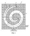
- FIG. 1 one example form of a separation device 20 is shown.
- This form shows an expanding spiral channel 22 with increasing radius of curvature. This geometry takes advantage of the rate of pressure change. Other configurations may also be used.
- the device may have a contracting spiral channel with a decreasing radius of curvature for the sidewalls. The radius of curvature and channel size may also be held substantially constant.
- the channel 22 evolves into two separate channels 24 and 26 (e.g. also referred to as channel #1 and channel #2 in Figure 1 ) to provide two outlet paths for the fluid.
- the particle separation may be driven by the centrifugal force or the pressure that is created by flow fluid through the channel.
- homogeneously distributed particles at the inlet are separated into a band, or populated in a portion of the fluid stream, and diverted at the outlet into a first portion or band including selected particulates and a second portion without such particulates resident therein.
- Patent Application filed on even date herewith, entitled “A Method and Apparatus for Splitting Fluid Flow in a Membraneless Particle Separation System” describes a variety of mechanisms and subsystems to enhance the splitting of the fluid flow at the outlet to provide enhancement for at least two outlet paths for the fluid.
- the system comprises a plurality of individual curved particle separation devices stacked such that the devices are parallel to one another and an inlet coupler connected to all inlets of the devices, the inlet couple being operative to facilitate input of fluid to all inlets of the plurality of individual curved particle separation devices.
- the curved particle separation devices are spiral devices.
- the curved particle separation devices comprise curved portions that span between 180 degrees and 360 degrees of angular distance along a diameter thereof.
- the system further comprises a feedback control system.
- the feedback control system is operative to control the system based on at least one of pressure, flow rate, bandwidth, viscosity, and temperature.
- system further comprises at least a second plurality of stacked curved particle separation devices arranged in parallel with the plurality of stacked curved particle separation devices.
- the system comprises an inlet manifold, a plurality of separation channels facilitating fluid flow therein and arranged in a helical spiral configuration wherein the channels are parallel to one another and an output manifold.
- the output manifold includes a portion therein operative to split the fluid flow from each of the channels.
- the portion is a static collar portion.
- the portion is a substantially circular collar portion.
- the portion is comprised of curves to provide a continuously adjustable split of the fluid flow.
- the portion is comprised of discrete step segments to provide a step-wise adjustable split of the fluid flow.
- the plurality of separation channels is arranged in a first stage and a second stage.
- the first stage and second stage are separated by a fluid inverter.
- the system further comprises a feedback control system.
- the feedback control system is operative to control the system based on at least one of pressure, flow rate, bandwidth, viscosity, and temperature.
- the system further comprises an inlet main and an outlet main.
- the system further comprises a second device connected to the inlet and outlet mains.
- a particle separation system comprising:
- FIGURE 1 is a representation of an example spiral particle separation device
- FIGURE 2 illustrates a form of the presently described embodiments
- FIGURE 3 illustrates a form of the presently described embodiments
- FIGURE 4 illustrates a form of the presently described embodiments
- FIGURE 5 illustrates a form of the presently described embodiments
- FIGURE 6 illustrates a form of the presently described embodiments
- FIGURE 7 illustrates a form of the presently described embodiments
- FIGURES 8(a)-8(d) illustrate a form of the presently described embodiments
- FIGURES 9(a)-9(b) illustrate a form of the presently described embodiments
- FIGURES 10(a) and 10(b) illustrate one form of the presently described embodiments
- FIGURES 11(a)-11(c) illustrate a form of the presently described embodiments
- FIGURES 12(a)-12(c) illustrate a form of the presently described embodiments
- FIGURES 13(a)-13(b) illustrate a form of the presently described embodiments
- FIGURES 14(a)-14(c) illustrate a form of the presently described embodiments.
- FIGURE 15 illustrates a form of the presently described embodiments.
- the presently described embodiments relate to various fluidic structures, implementations and selected fabrication techniques to realize construction of fluidic separation structures that are of a stacked and/or parallel configuration. These contemplated systems provide for efficient input of fluid to be processed, improved throughput, and, in some variations, adjustable and efficient treatment of output fluid.
- Planar embodiments utilizing convenient stacking techniques are contemplated.
- circular arcs that do not complete a spiral
- Other planar embodiments described herein include helical spirals.
- the presently contemplated embodiments may be fabricated from inexpensive materials such as PDMS for microscale, inexpensive plastics (such as acrylic, Lucite and polycarbonate) for miniscale and macroscale applications. Selected fabrication techniques for some of these embodiments are also described.
- a parallel eight channel helical spiral embodiment provides for quick assembly and disassembly. Notable features of such a contemplated device include convenient inlet manifolds and outlet manifolds that include a bifurcating mechanism or splitter to split the fluid into particulate and effluent fluid streams. The contemplated embodiments also allow for a multiple stage device operative to output an extremely narrow band of particulates for further disposal or processing. Other parallel configuration embodiments and fabrication techniques therefor are contemplated. Also, a feedback and/or control system may be implemented with any of the presently described embodiments.
- the device 30 has an inlet 32, at least one curved or spiral portion 34 and an outlet 36.
- This planar multi-spiral channel device 30, in one form, may be cut from plastic.
- the type of plastic may vary as a function of the specific application and the environment in which it is implemented.
- the center region of the device 30 near the inlet 32 may be removed to allow access for an inlet coupler to be described hereafter.
- the spirals portion 34 of the device may take a variety of forms.
- the spiral portion 34 may be converging or diverging.
- the outlet 36 and inlet 32 locations may be interchanged to suit the application, e.g. for increasing or decreasing centrifugal forces.
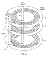
- a system 40 is representatively shown and comprises a plurality of devices 30 (shown in Figure 2 ) stacked in a parallel manner to allow for N-layers of parallel processing of fluid.
- an inlet coupler 42 which allows for input fluid to be provided to each device 30 within the entire stack from a common supply source.
- the inlet coupler 42 may take a variety of forms; however, in one example, the inlet coupler 42 is cylindrical and has perforations formed therein. The perforations correspond to inlets of the devices 30 stacked in the system 40. Outlet couplers of a similar configuration may also be implemented.
- Two outlet couplers 44 and 46 are representatively shown here, although the number of outlet couplers could vary based on the number of outlet paths or channels for each stacked device.
- the inlet coupler may be joined only with the top channel through an external Al plate, for example. Fluidic connection to all layers may be achieved by punching through all the top layers except for the bottom. At least two fluidic outlets, or outlet couplers such as those shown at 44 and 46, may be connected in the same manner on the top plate. All inlet and outlets connections may also be implemented on the bottom plate.
- a system 50 comprises multiple planar curved arc segments 52 (e.g. fractional arc segments) that are vertically stacked as parallel channels to increase throughput. These planar curved arc segments do not complete a loop for any one segment 52, although the characteristics and functions of a spiral device will nonetheless apply to these segments 52 in this case.
- the arc segments or curved portions 52 comprise an inlet 54, curved or arc section 56 and an outlet 58. Also shown in Figure 4 is an inlet coupler 60 that, again, allows for an inlet of fluid from a common source to all of the separate arc segments shown. It should be appreciated that the inlet coupler may take a variety of forms.
- the inlet coupler is a cylinder and has perforations or a continuous slot corresponding to the inlet of each layer.
- the system 50 provides for increased throughput for fluid particle separation.
- At least one outlet coupler may also be implemented.
- the outlet coupler(s) could resemble the inlet coupler of Figure 3 or 4 , for example.
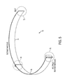
- FIG. 5 another planar curved structure 70 comprising stacked channels (not shown individually) is shown.
- the curved structure 70 has an inlet 72 (which may include an inlet coupler), curved portions 74 and 76, and at least one outlet 78 or 79.
- the outlet 78 is positioned midway around the curve between the curved portion 74 and curved portion 76.
- a second outlet 79 for selected particles of a second size or density (e.g. neutrally buoyant particles) is positioned at an end of the curve opposite the inlet 72.
- these outlets 78 and 79 can be used to remove particles of varying sizes or densities from the fluid flow.
- at least one outlet coupler may also be utilized.
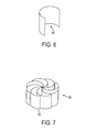
- the system 80 comprises a plurality of devices 70, as shown in Figure 5 , that are stacked in a configuration to allow for increased throughput by way of parallel processing. It should be appreciated that the system 80 may also comprise a single device 70 of increased width. Of course, as above, an inlet coupler and/or at least one outlet coupler may be implemented in the system.
- a system 90 is illustrated.
- the system 90 represents a still further implementation of a plurality of systems 80 of Figure 6 .
- This design may be advantageous as a function of the space requirements of the system and/or environment into which the presently described embodiments are implemented.
- the inlet for all of the curved separation device sections is at the center of the configuration of system 90.
- an inlet coupler such as an inlet coupler 42 ( Figure 3 ) and inlet coupler 60 ( Figure 4 ).
- an outlet coupler, or couplers may also be implemented.
- Figures 8(a)-8(d) it will be appreciated that the stacked and/or parallel embodiments of Figures 3 , 4 , 5 , 6 and 7 may be fabricated using a variety of different techniques.
- Figures 8(a)-8(d) show various cross sections of different embodiments of the presently described embodiments. These figures also provide description of fabrication details that may be used to form the presently described embodiments.
- FIG. 8(a) a cross-sectional view of a configuration 100 is illustrated.
- tubing 102 is disposed within chambers defined between endplates 106.
- the chambers are defined by plates 104 and spacers 108, as shown.
- the tubing 102 is controllably squeezed between the plates 104.
- assembly procedures may be used.
- materials may be used.
- the end plates 106 are formed of aluminum
- the tubing 102 is formed of Tygon material
- the spacers 108 and plates 104 are formed of plastic, such as Plexiglas.
- a similar structure 110 is provided except the tubing 102 is recessed within a cavity 114 formed in a plate 112 and stacked to increase throughput.
- the plates also are provided with alignment notches 116. Any suitable material may be used to form the plates 112, including a plastic material such as Plexiglas.
- a system 120 is illustrated wherein tubing 102 is eliminated.
- sufficiently sealed cavities 124 are formed in a substrate 122 and form the fluid channels which are stacked to increase throughput.
- a cap layer 128 to seal the top cavity 124.
- alignment notches 126 are also provided.
- the substrate 122 and cover plate 128 may be formed of any suitable material; however, in at least one form, these elements are formed of plastic material such as Plexiglas.
- a system 130 comprises spiral tracks 132 defined by wall portions 134 and plates 136.
- the wall portions 134 and the plates 136 may take a variety of forms. But, in one form, these structures are formed of plastic. Essentially, the structure 134 is formed and then laminated on both sides to form the enclosed channels 132. Again, these parallel devices are stacked for improved support and throughput. As with Figure 8(a) - (c) , both ends are supported by plates formed of, for example, aluminum.
- Figures 9(a) - (b) illustrate a further embodiment of the presently described embodiments.
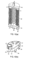
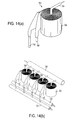
- a device 200 includes eight parallel channels in a helical spiral arrangement. This embodiment provides for quick assembly and disassembly, as shown in the exploded view of Figure 9(b) , the cross-sectional view of Figure 10(a) and the end cap and manifold structure of Figure 10(b) .
- An upper fluidic manifold 210 feeds the eight separate channels (such as channel 214) through the respective radially skewed slots on an end cap 212.
- a lower end cap 216 has slots corresponding to each channel as well as corresponding chutes 217.
- An outlet manifold 218 includes an inner ring 219 which acts as the bifurcator to split the fluid into particulate and effluent streams.
- the helical spiral structure formed by the channels fits within an external protective sleeve 220. It will be appreciated that, in one form, the device 200 is tightened by counter rotating the top and bottom manifold and end cap structures. Tightening pushes the helical spirals against each other, thus preventing distortions to the individual flow cross sections and, therefore, allowing the use of thinner and less expensive materials and a further reduction in space.
- Each individual channel may optionally have individual flow control at inlet or outlet to stop the flow.
- parallel channels allow for redundancy when clogging develops in a channel as the other channels will take up the slack to continue operation.
- a flow sensor can be incorporated within a feedback loop to adjust the flow rate in order to maintain a constant separation velocity.
- other inline devices such as flash mixers may be integrated with the top manifold. The eight channels are shown to illustrate parallelization, but any number of channels may be used.
- the spiral separator will collect all of the particulates into a band of different widths.
- an outlet manifold 218 having such a stream splitter is illustrated.
- the splitting mechanism can take a variety of forms as will be describe in connection with Figures 11 (a) - (c) ; however, in at least one form, the splitter will allow for the fluid to be split so that a portion 222 will exit the device on a first path as effluent and a portion 224 of the fluid will exit the device on a second path containing particles (e.g. a particle band).
- the splitter is connected to the spiral separator device 200 such that it can be rotated on its central axis.
- the splitter typically will rotate only about 45 degrees.
- the degree of radial change of the splitter wall can be optimized to the expected source water quality. For example, if the quality is expected to vary only slightly, a smaller change in radius is sufficient to capture the range of width change. If variations in water quality are larger, a larger change in radius may be necessary.
- the adjustable splitter is operated manually, feedback from inline meters and other sensors may be used. Another manner of operating the splitter is to provide an automated feedback loop. In this way, optical sensors can be used at the exit portion of the channels to measure the bandwidth constantly and direct a server or motor to adjust the optimal splitter setting in real time. Similarly, flow sensors can also be used to monitor flow rate for feedback control of fluid velocity by adjusting pump speed and/or power.
- Figure 11 (a) shows a static splitter.
- the manifold 218 is provided with a substantially circular collar device 219 to act as a splitter. Collar devices with pre-set splits of 20:80, 30:70, through 80:20 may be used interchangeably.
- Figure 11(b) shows a continuously adjustable flow separator providing for non-linear control in custom curvature.
- the manifold 218' is provided with a portion 219' that includes strategically placed curved and straight portions to provide for the continuously adjustable flow.
- Figure 11(c) shows a discrete stepwise adjustable flow separator design.
- the manifold 218" includes a portion 219" that is formed by discrete steps to provide discrete step-wise adjustable flow. In this form, the transition from one step to the next may be ratcheted.
- the splitters in any of these forms and others, are adjusted by turning the manifold of the device in a selected direction for a selected angular distance. This will move the splitting mechanism across the egress portion of the channel so that the split between the path 222 and the path 224 may be varied. Adjustments may be automated by a motor controlled by a computer.
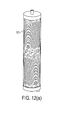
- Figures 12(a) and (b) show an extension of the embodiment in Figures 9(a)-11(c) , wherein a modular eight channel two stage helical spiral embodiment is illustrated.
- a fluid inverter 316 is provided in the embodiment shown.
- the fluid inverter is comprised of circular plates 326 and 328, having slots therein corresponding to the spiral channels.
- the fluid inverter also includes passageways 330 connecting corresponding slots in the plates 326 and 328.
- a fluid inversion is initiated in the fluid flow so that any resident particle band flips from one side of the channel to the other side of the channel to provide a compaction of particles. This achieves a narrower band.
- a first stage 314 is illustrated as well as a second spiral stage 315.
- the spiral stage 315 is flipped upside down.
- the fluid inverter 316 is positioned between the stages.
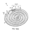
- a spiral device 350 includes an inlet 352, a first curved portion or stage 354 of the spiral channel, a transition 356, a second curved portion or stage 358 and outlets 360, 362 and 364.
- the fluid is received at the inlet 352 and flows through the first stage 354 - with particles being separated and, in some forms, being focused in a particle band, on one side of the channel.
- the band or separated particles flips to the opposite side of the channel.
- the second stage 358 then continues to compact the particles resulting in a more compact and even narrower band of particles.
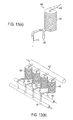
- a spiral device 600 according to the presently described embodiments is illustrated.
- the spiral device 600 takes the form of a helical spiral.
- the spiral body portion of the device 604 is a helical spiral that has an inlet 606, a first outlet 608 and a second outlet 610.
- this single channel helical structure resembles a hollow "slinky" type device with the shape of a coiled spring.
- This device may be fabricated in a variety of manners including in sections using injection molding techniques. The sections are then fused together using known processes before use.
- Another process for fabricating this device includes the use of extrusion molding techniques wherein the extruded plastic can be air-cooled or dipped in a liquid bath to solidify to its desired shape and structure.
- the helical coiling can be achieved by controlling the rotation of either the extrusion mandril or the cooling bath.
- thermal plastics such as PVC with Shore "A" hardness, high density polyethylene, polypropylene, polystyrene, and polycarbonate.
- a spiral device such as that shown in Figure 13(a) can be disposed in a parallel arrangement to increase throughput of the system.
- spiral devices 600 are all connected to an input main 620 from a fluid manifold and the respective first outlets of the devices 600 are connected to a first outlet main 622.
- the second outlets of the devices 600 are connected to a second outlet main 624.
- FIG. 14(a) shows a spiral device 700 that is a spiral wound device.
- This device 700 includes a spirally wound body 704 having inlet 706, a first outlet 708 and a second outlet 710.
- Such a device may be fabricated by introducing rib structures on a web-fed Mylar-like plastic (or fluid impermeable) material.
- the rib structures may be formed using quick-set epoxy printing techniques.
- the device 700 may be disposed in a system wherein a plurality of devices 700 are connected in parallel to a water inlet main 720 from a fluid manifold. Similarly, the first outlet lines for the devices are connected to a first outlet main 722. The second outlet lines of the devices 700 are connected to a second outlet main 724.
- the body 704 may be comprised of a single channel 1210, or a plurality of channels 1210 - 1224. Of course, any number or form of channels will suffice.
- any of the spiral or other devices described or contemplated herein may be disposed in a cascaded manner or in a parallel manner, as shown in Figures 13(a), 13(b) , 14(a) and 14(b) . Those actually shown are merely examples. Still further, any suitable material may be used to form the devices contemplated herein.
- a separator 902 (which could take the form of any of the spiral or other separators contemplated by the presently described embodiments or others) receives input fluid 904 and processes it to achieve an effluent stream 906 and a particulate stream 908.
- the system 900 may use various items of data, such as pressure, bandwidth, flow rate, temperature or viscosity - all of which may be measured using suitable sensors.
- the data is fed to a controller 910 that controls various actuators 920 that are operative to modify the performance of the device 902 in a desired manner.
Landscapes
- Chemical & Material Sciences (AREA)
- Chemical Kinetics & Catalysis (AREA)
- Separation Of Solids By Using Liquids Or Pneumatic Power (AREA)
- Physical Or Chemical Processes And Apparatus (AREA)
- Cyclones (AREA)
- Separation Using Semi-Permeable Membranes (AREA)
Abstract
Fluidic structures for facilitating particle separation in curved or spiral devices are provided. The contemplated systems relate to various fluidic structures, implementations and selected fabrication techniques to realize construction of fluidic separation structures that are of a stacked and/or parallel configuration. These contemplated systems provide for efficient input of fluid to be processed, improved throughput, and, in some variations, adjustable and efficient treatment of output fluid.
Description
- Several different types of membraneless particle separation devices having a generally spiral or curved configuration have been described in
U.S. Patent Application Serial No. 11/606,460 ,U.S. Patent Application Serial No. 11/936,729 ,U.S. Application Serial No. 11/936,753 , and co-pending, commonly assigned U.S. Patent Application filed on even date herewith, entitled "A Method and Apparatus for Splitting Fluid Flow in a Membraneless Particle Separation System". - In general, such devices are useful in connection with particles having density differences compared with water, thus creating centrifugal or buoyancy forces necessary for transverse migration through the channel for purposes of separation. Some of these devices are also useful, depending on their configuration, to separate neutrally buoyant particles.
- With reference to
Figure 1 , one example form of aseparation device 20 is shown. This form shows an expandingspiral channel 22 with increasing radius of curvature. This geometry takes advantage of the rate of pressure change. Other configurations may also be used. In another form, the device may have a contracting spiral channel with a decreasing radius of curvature for the sidewalls. The radius of curvature and channel size may also be held substantially constant. In any case, thechannel 22 evolves into twoseparate channels 24 and 26 (e.g. also referred to aschannel # 1 andchannel # 2 inFigure 1 ) to provide two outlet paths for the fluid. - These types of separation devices provide for particle separation in a variety of manners. For example, depending on the flow rate, the particle separation may be driven by the centrifugal force or the pressure that is created by flow fluid through the channel. In any event, it is the objective of such devices to achieve particle separation. In this regard, homogeneously distributed particles at the inlet are separated into a band, or populated in a portion of the fluid stream, and diverted at the outlet into a first portion or band including selected particulates and a second portion without such particulates resident therein. Co-pending, commonly assigned U.S. Patent Application filed on even date herewith, entitled "A Method and Apparatus for Splitting Fluid Flow in a Membraneless Particle Separation System" describes a variety of mechanisms and subsystems to enhance the splitting of the fluid flow at the outlet to provide enhancement for at least two outlet paths for the fluid.
- Designs and implementations of these types of devices for different environments and incorporating selected improvements are desired.
- In one aspect of the presently described embodiments, the system comprises a plurality of individual curved particle separation devices stacked such that the devices are parallel to one another and an inlet coupler connected to all inlets of the devices, the inlet couple being operative to facilitate input of fluid to all inlets of the plurality of individual curved particle separation devices.
- In another aspect of the presently described embodiments, the curved particle separation devices are spiral devices.
- In another aspect of the presently described embodiments, the curved particle separation devices comprise curved portions that span between 180 degrees and 360 degrees of angular distance along a diameter thereof.
- In another aspect of the presently described embodiments, the system further comprises a feedback control system.
- In another aspect of the presently described embodiments, the feedback control system is operative to control the system based on at least one of pressure, flow rate, bandwidth, viscosity, and temperature.
- In another aspect of the presently described embodiments, the system further comprises at least a second plurality of stacked curved particle separation devices arranged in parallel with the plurality of stacked curved particle separation devices.
- In another aspect of the presently described embodiments, the system comprises an inlet manifold, a plurality of separation channels facilitating fluid flow therein and arranged in a helical spiral configuration wherein the channels are parallel to one another and an output manifold.
- In another aspect of the presently described embodiments, the output manifold includes a portion therein operative to split the fluid flow from each of the channels.
- In another aspect of the presently described embodiments, the portion is a static collar portion.
- In another aspect of the presently described embodiments, the portion is a substantially circular collar portion.
- In another aspect of the presently described embodiments, the portion is comprised of curves to provide a continuously adjustable split of the fluid flow.
- In another aspect of the presently described embodiments, the portion is comprised of discrete step segments to provide a step-wise adjustable split of the fluid flow.
- In another aspect of the presently described embodiments, the plurality of separation channels is arranged in a first stage and a second stage.
- In another aspect of the presently described embodiments, the first stage and second stage are separated by a fluid inverter.
- In another aspect of the presently described embodiments, the system further comprises a feedback control system.
- In another aspect of the presently described embodiments, the feedback control system is operative to control the system based on at least one of pressure, flow rate, bandwidth, viscosity, and temperature.
- In another aspect of the presently described embodiments, the system further comprises an inlet main and an outlet main.
- In another aspect of the presently described embodiments, the system further comprises a second device connected to the inlet and outlet mains.
Herein it is provided as a first embodiment a particle separation system comprising: - a plurality of individual curved particle separation devices stacked such that the devices are parallel to one another;
- an inlet coupler connected to all inlets of the devices, the inlet couple being operative to facilitate input of fluid to all inlets of the plurality of individual curved particle separation devices; and
- at least two outlet couplers connected to the corresponding outlets of the plurality of individual curved particle separation devices.
-
FIGURE 1 is a representation of an example spiral particle separation device; -
FIGURE 2 illustrates a form of the presently described embodiments; -
FIGURE 3 illustrates a form of the presently described embodiments; -
FIGURE 4 illustrates a form of the presently described embodiments; -
FIGURE 5 illustrates a form of the presently described embodiments; -
FIGURE 6 illustrates a form of the presently described embodiments; -
FIGURE 7 illustrates a form of the presently described embodiments; -
FIGURES 8(a)-8(d) illustrate a form of the presently described embodiments; -
FIGURES 9(a)-9(b) illustrate a form of the presently described embodiments; -
FIGURES 10(a) and 10(b) illustrate one form of the presently described embodiments; -
FIGURES 11(a)-11(c) illustrate a form of the presently described embodiments; -
FIGURES 12(a)-12(c) illustrate a form of the presently described embodiments -
FIGURES 13(a)-13(b) illustrate a form of the presently described embodiments; -
FIGURES 14(a)-14(c) illustrate a form of the presently described embodiments; and -
FIGURE 15 illustrates a form of the presently described embodiments. - The presently described embodiments relate to various fluidic structures, implementations and selected fabrication techniques to realize construction of fluidic separation structures that are of a stacked and/or parallel configuration. These contemplated systems provide for efficient input of fluid to be processed, improved throughput, and, in some variations, adjustable and efficient treatment of output fluid.
- It will be understood that variations of these devices may be realized based on dimensional scale and channel architecture. However, it is contemplated that the embodiments described herein will be highly scalable to span microscale (0 to 10 mL/min), miniscale (10-1000 mL/min), and macroscale (1-10 L/min) single-channel flow rates.
- Planar embodiments utilizing convenient stacking techniques are contemplated. In this regard, circular arcs (that do not complete a spiral) in the range of 180 to 360 degrees allow for sequential stages of transverse flow pattern development, attainment of steady state flow velocity and time for several circulatory passes to sweep particles to a desired position in the fluid flow. Other planar embodiments described herein include helical spirals.
- The presently contemplated embodiments may be fabricated from inexpensive materials such as PDMS for microscale, inexpensive plastics (such as acrylic, Lucite and polycarbonate) for miniscale and macroscale applications. Selected fabrication techniques for some of these embodiments are also described.
- In addition, a parallel eight channel helical spiral embodiment provides for quick assembly and disassembly. Notable features of such a contemplated device include convenient inlet manifolds and outlet manifolds that include a bifurcating mechanism or splitter to split the fluid into particulate and effluent fluid streams. The contemplated embodiments also allow for a multiple stage device operative to output an extremely narrow band of particulates for further disposal or processing. Other parallel configuration embodiments and fabrication techniques therefor are contemplated. Also, a feedback and/or control system may be implemented with any of the presently described embodiments.
- With reference now to
Figure 2 , a single planarspiral separation device 30 is illustrated. Thedevice 30 has aninlet 32, at least one curved orspiral portion 34 and anoutlet 36. This planarmulti-spiral channel device 30, in one form, may be cut from plastic. The type of plastic may vary as a function of the specific application and the environment in which it is implemented. In one variation of thedevice 30, the center region of thedevice 30 near theinlet 32 may be removed to allow access for an inlet coupler to be described hereafter. Thespirals portion 34 of the device may take a variety of forms. For example, thespiral portion 34 may be converging or diverging. As a further example, theoutlet 36 andinlet 32 locations may be interchanged to suit the application, e.g. for increasing or decreasing centrifugal forces. - It should be appreciated that the fundamental operation of individual curved or spiral separation devices to separate particles in fluid, such as
device 30 or other devices contemplated herein, is described in detail in selected portions of the above referenced patent applications (which are incorporated herein by reference). Therefore, such operation will not be described herein except to the extent that such description will enhance the description of the presently described embodiments. - With reference to
Figure 3 , asystem 40 is representatively shown and comprises a plurality of devices 30 (shown inFigure 2 ) stacked in a parallel manner to allow for N-layers of parallel processing of fluid. Also representatively shown inFigure 3 is aninlet coupler 42 -- which allows for input fluid to be provided to eachdevice 30 within the entire stack from a common supply source. Theinlet coupler 42 may take a variety of forms; however, in one example, theinlet coupler 42 is cylindrical and has perforations formed therein. The perforations correspond to inlets of thedevices 30 stacked in thesystem 40. Outlet couplers of a similar configuration may also be implemented. Twooutlet couplers - With reference to
Figure 4 , asystem 50 comprises multiple planar curved arc segments 52 (e.g. fractional arc segments) that are vertically stacked as parallel channels to increase throughput. These planar curved arc segments do not complete a loop for any onesegment 52, although the characteristics and functions of a spiral device will nonetheless apply to thesesegments 52 in this case. The arc segments orcurved portions 52 comprise aninlet 54, curved orarc section 56 and anoutlet 58. Also shown inFigure 4 is aninlet coupler 60 that, again, allows for an inlet of fluid from a common source to all of the separate arc segments shown. It should be appreciated that the inlet coupler may take a variety of forms. In one form, the inlet coupler is a cylinder and has perforations or a continuous slot corresponding to the inlet of each layer. Like thesystem 40 ofFigure 3 , thesystem 50 provides for increased throughput for fluid particle separation. At least one outlet coupler (not shown) may also be implemented. The outlet coupler(s) could resemble the inlet coupler ofFigure 3 or4 , for example. - With reference to
Figure 5 , another planarcurved structure 70 comprising stacked channels (not shown individually) is shown. Thecurved structure 70 has an inlet 72 (which may include an inlet coupler),curved portions outlet 78 or 79. As shown, there is anoutlet 78 for selected particles such as particles of a particular size or density (e.g. buoyant particles). Theoutlet 78 is positioned midway around the curve between thecurved portion 74 andcurved portion 76. A second outlet 79 for selected particles of a second size or density (e.g. neutrally buoyant particles) is positioned at an end of the curve opposite theinlet 72. In general, theseoutlets 78 and 79 can be used to remove particles of varying sizes or densities from the fluid flow. As above, at least one outlet coupler may also be utilized. - With reference to
Figure 6 , asystem 80 is shown. Thesystem 80 comprises a plurality ofdevices 70, as shown inFigure 5 , that are stacked in a configuration to allow for increased throughput by way of parallel processing. It should be appreciated that thesystem 80 may also comprise asingle device 70 of increased width. Of course, as above, an inlet coupler and/or at least one outlet coupler may be implemented in the system. - With reference to
Figure 7 , asystem 90 is illustrated. Thesystem 90 represents a still further implementation of a plurality ofsystems 80 ofFigure 6 . This design may be advantageous as a function of the space requirements of the system and/or environment into which the presently described embodiments are implemented. Notably, as shown, the inlet for all of the curved separation device sections is at the center of the configuration ofsystem 90. This allows for efficient processing of the input fluid and may be realized by use of an inlet coupler, such as an inlet coupler 42 (Figure 3 ) and inlet coupler 60 (Figure 4 ). Again, an outlet coupler, or couplers, may also be implemented. - With reference to
Figures 8(a)-8(d) , it will be appreciated that the stacked and/or parallel embodiments ofFigures 3 ,4 ,5 ,6 and 7 may be fabricated using a variety of different techniques.Figures 8(a)-8(d) show various cross sections of different embodiments of the presently described embodiments. These figures also provide description of fabrication details that may be used to form the presently described embodiments. - With reference to
Figure 8(a) , a cross-sectional view of aconfiguration 100 is illustrated. In this form,tubing 102 is disposed within chambers defined betweenendplates 106. The chambers are defined by plates 104 andspacers 108, as shown. In this configuration, thetubing 102 is controllably squeezed between the plates 104. To achieve theconfiguration 100, a variety of different assembly procedures may be used. Likewise, a variety of different materials may be used. However, in one form of the configuration ofFigure 8(a) (and in corresponding example elements ofFigures 8(b) -(d) ), theend plates 106 are formed of aluminum, thetubing 102 is formed of Tygon material, and thespacers 108 and plates 104 are formed of plastic, such as Plexiglas. - In
Figure 8(b) , asimilar structure 110 is provided except thetubing 102 is recessed within acavity 114 formed in aplate 112 and stacked to increase throughput. The plates also are provided withalignment notches 116. Any suitable material may be used to form theplates 112, including a plastic material such as Plexiglas. - With reference to
Figure 8(c) , asystem 120 is illustrated whereintubing 102 is eliminated. In this case, sufficiently sealedcavities 124 are formed in asubstrate 122 and form the fluid channels which are stacked to increase throughput. Also shown is acap layer 128 to seal thetop cavity 124. LikeFigure 8(b) ,alignment notches 126 are also provided. Thesubstrate 122 andcover plate 128 may be formed of any suitable material; however, in at least one form, these elements are formed of plastic material such as Plexiglas. - With reference to
Figure 8(d) , asystem 130 comprisesspiral tracks 132 defined bywall portions 134 andplates 136. Thewall portions 134 and theplates 136 may take a variety of forms. But, in one form, these structures are formed of plastic. Essentially, thestructure 134 is formed and then laminated on both sides to form theenclosed channels 132. Again, these parallel devices are stacked for improved support and throughput. As withFigure 8(a) - (c) , both ends are supported by plates formed of, for example, aluminum. -
Figures 9(a) - (b) illustrate a further embodiment of the presently described embodiments. As shown inFigure 9(a) , adevice 200 includes eight parallel channels in a helical spiral arrangement. This embodiment provides for quick assembly and disassembly, as shown in the exploded view ofFigure 9(b) , the cross-sectional view ofFigure 10(a) and the end cap and manifold structure ofFigure 10(b) . - In operation, fluid enters the
device 200 through aninlet 202 and exits (separated) throughoutlet paths upper fluidic manifold 210 feeds the eight separate channels (such as channel 214) through the respective radially skewed slots on anend cap 212. Alower end cap 216 has slots corresponding to each channel as well ascorresponding chutes 217. Anoutlet manifold 218 includes aninner ring 219 which acts as the bifurcator to split the fluid into particulate and effluent streams. - The helical spiral structure formed by the channels, such as
channel 214, fits within an externalprotective sleeve 220. It will be appreciated that, in one form, thedevice 200 is tightened by counter rotating the top and bottom manifold and end cap structures. Tightening pushes the helical spirals against each other, thus preventing distortions to the individual flow cross sections and, therefore, allowing the use of thinner and less expensive materials and a further reduction in space. Each individual channel may optionally have individual flow control at inlet or outlet to stop the flow. - Although design is somewhat self-cleaning as it operates at velocities in the range of 0.1 to 10 m/s, parallel channels allow for redundancy when clogging develops in a channel as the other channels will take up the slack to continue operation. Optionally, a flow sensor can be incorporated within a feedback loop to adjust the flow rate in order to maintain a constant separation velocity. Additionally, other inline devices such as flash mixers may be integrated with the top manifold. The eight channels are shown to illustrate parallelization, but any number of channels may be used.
- Depending on the source water quality, i.e. particulate concentration and size distribution, the spiral separator will collect all of the particulates into a band of different widths. In order to allow optimization of the efficiency of the spiral concentrator in real time, it is desirable to have an adjustable stream splitter.
- With reference now to
Figures 10(a) and 10(b) , anoutlet manifold 218 having such a stream splitter is illustrated. The splitting mechanism can take a variety of forms as will be describe in connection withFigures 11 (a) - (c) ; however, in at least one form, the splitter will allow for the fluid to be split so that aportion 222 will exit the device on a first path as effluent and aportion 224 of the fluid will exit the device on a second path containing particles (e.g. a particle band). - The splitter is connected to the
spiral separator device 200 such that it can be rotated on its central axis. For adevice 200 with eight parallel channels, the splitter typically will rotate only about 45 degrees. The degree of radial change of the splitter wall can be optimized to the expected source water quality. For example, if the quality is expected to vary only slightly, a smaller change in radius is sufficient to capture the range of width change. If variations in water quality are larger, a larger change in radius may be necessary. When the adjustable splitter is operated manually, feedback from inline meters and other sensors may be used. Another manner of operating the splitter is to provide an automated feedback loop. In this way, optical sensors can be used at the exit portion of the channels to measure the bandwidth constantly and direct a server or motor to adjust the optimal splitter setting in real time. Similarly, flow sensors can also be used to monitor flow rate for feedback control of fluid velocity by adjusting pump speed and/or power. - With reference to
Figures 11(a)-11(c) , various forms of the output fluid manifold are shown.Figure 11 (a) shows a static splitter. In this form, the manifold 218 is provided with a substantiallycircular collar device 219 to act as a splitter. Collar devices with pre-set splits of 20:80, 30:70, through 80:20 may be used interchangeably.Figure 11(b) shows a continuously adjustable flow separator providing for non-linear control in custom curvature. In this form, the manifold 218' is provided with a portion 219' that includes strategically placed curved and straight portions to provide for the continuously adjustable flow.Figure 11(c) shows a discrete stepwise adjustable flow separator design. In this form, the manifold 218" includes aportion 219" that is formed by discrete steps to provide discrete step-wise adjustable flow. In this form, the transition from one step to the next may be ratcheted. - The splitters, in any of these forms and others, are adjusted by turning the manifold of the device in a selected direction for a selected angular distance. This will move the splitting mechanism across the egress portion of the channel so that the split between the
path 222 and thepath 224 may be varied. Adjustments may be automated by a motor controlled by a computer. -
Figures 12(a) and (b) show an extension of the embodiment inFigures 9(a)-11(c) , wherein a modular eight channel two stage helical spiral embodiment is illustrated. Afluid inverter 316 is provided in the embodiment shown. The fluid inverter is comprised ofcircular plates passageways 330 connecting corresponding slots in theplates Figures 12(a) and12(b) , a fluid inversion is initiated in the fluid flow so that any resident particle band flips from one side of the channel to the other side of the channel to provide a compaction of particles. This achieves a narrower band. InFigure 12(b) , afirst stage 314 is illustrated as well as asecond spiral stage 315. To achieve the above noted flipping of the particle band, thespiral stage 315 is flipped upside down. Thefluid inverter 316 is positioned between the stages. - To further explain the principles of the inversion process, reference is made to
Figure 12(c) . It will be appreciated that the embodiment ofFigure 12 (c) differs in structure from the embodiment ofFigures 12 (a) and(b) in that the spiral device is of a different configuration and an inverter structure, such asinverter 316, is not shown. Nonetheless, it will be appreciated by those of skill in the art that the inversion principles as explained in connection with this drawing can be applied to the inversion process of theinverter 316. As shown, aspiral device 350 includes aninlet 352, a first curved portion or stage 354 of the spiral channel, atransition 356, a second curved portion orstage 358 andoutlets inlet 352 and flows through the first stage 354 - with particles being separated and, in some forms, being focused in a particle band, on one side of the channel. As the fluid passed through theabrupt transition point 356, the band (or separated particles) flips to the opposite side of the channel. Thesecond stage 358 then continues to compact the particles resulting in a more compact and even narrower band of particles. - With reference now to
Figures 13 (a) and (b) , a still further embodiment is shown. InFigures 13 (a) and (b) , aspiral device 600 according to the presently described embodiments is illustrated. In this embodiment, thespiral device 600 takes the form of a helical spiral. In this regard, the spiral body portion of thedevice 604 is a helical spiral that has aninlet 606, afirst outlet 608 and asecond outlet 610. It will be appreciated that this single channel helical structure resembles a hollow "slinky" type device with the shape of a coiled spring. This device may be fabricated in a variety of manners including in sections using injection molding techniques. The sections are then fused together using known processes before use. Another process for fabricating this device includes the use of extrusion molding techniques wherein the extruded plastic can be air-cooled or dipped in a liquid bath to solidify to its desired shape and structure. The helical coiling can be achieved by controlling the rotation of either the extrusion mandril or the cooling bath. A variety of different material can be used, including thermal plastics such as PVC with Shore "A" hardness, high density polyethylene, polypropylene, polystyrene, and polycarbonate. - As shown in
Figure 13(b) , a spiral device such as that shown inFigure 13(a) can be disposed in a parallel arrangement to increase throughput of the system. As shown,spiral devices 600 are all connected to an input main 620 from a fluid manifold and the respective first outlets of thedevices 600 are connected to a first outlet main 622. The second outlets of thedevices 600 are connected to a second outlet main 624. - With reference to
Figures 14(a) through 14(c) , a similar system having vertically stacked parallel channels is shown. However, the embodiment ofFigure 14(a) shows aspiral device 700 that is a spiral wound device. Thisdevice 700 includes aspirally wound body 704 havinginlet 706, afirst outlet 708 and asecond outlet 710. Such a device may be fabricated by introducing rib structures on a web-fed Mylar-like plastic (or fluid impermeable) material. The rib structures may be formed using quick-set epoxy printing techniques. - As with the embodiment illustrated in
Figures 13(a) and 13(b) , thedevice 700, as shown inFigure 14(b) , may be disposed in a system wherein a plurality ofdevices 700 are connected in parallel to a water inlet main 720 from a fluid manifold. Similarly, the first outlet lines for the devices are connected to a first outlet main 722. The second outlet lines of thedevices 700 are connected to a second outlet main 724. - With reference to
Figure 14(c) , it will be appreciated that thebody 704 may be comprised of asingle channel 1210, or a plurality of channels 1210 - 1224. Of course, any number or form of channels will suffice. - Moreover, it should be appreciated that any of the spiral or other devices described or contemplated herein may be disposed in a cascaded manner or in a parallel manner, as shown in
Figures 13(a), 13(b) ,14(a) and 14(b) . Those actually shown are merely examples. Still further, any suitable material may be used to form the devices contemplated herein. - With reference now to
Figure 15 , an example feedback andcontrol system 900 is illustrated. As shown, a separator 902 (which could take the form of any of the spiral or other separators contemplated by the presently described embodiments or others) receivesinput fluid 904 and processes it to achieve aneffluent stream 906 and aparticulate stream 908. As alluded to above, thesystem 900 may use various items of data, such as pressure, bandwidth, flow rate, temperature or viscosity - all of which may be measured using suitable sensors. The data is fed to acontroller 910 that controlsvarious actuators 920 that are operative to modify the performance of thedevice 902 in a desired manner. - It will be appreciated that various of the above-disclosed and other features and functions, or alternatives thereof, may be desirably combined into many other different systems or applications.
According to another example in the first embodiment the curved particle separation devices comprise curved portions that span between 180 degrees and 360 degrees of angular distance along a diameter thereof.
The system of the first embodiment may further comprise a feedback control system. In this case, the feedback control system may be operative to control the system based on at least one of pressure, flow rate, bandwidth, viscosity, and temperature.
The system of the first embodiment may further comprise at least a second plurality of stacked curved particle separation devices arranged in parallel with the plurality of stacked curved particle separation devices.
It is provided as a second embodiment a particle separation system comprising: an inlet manifold;
a plurality of separation channels facilitating fluid flow therein and arranged in a helical spiral configuration wherein the channels are parallel to one another; and an output manifold.
According to an example of the second embodiment the output manifold includes a portion therein operative to split the fluid flow from each of the channels. In this example the portion may be a static collar portion, a substantially circular collar portion, comprised of curves to provide a continuously adjustable split of the fluid flow, or comprised of discrete step segments to provide a step-wise adjustable split of the fluid flow. Moreover, in this example the plurality of separation channels may be arranged in a first stage and a second stage. In this case, the first stage and second stage may be separated by a fluid inverter.
The system of the second embodiment may further comprise a feedback control system.
Claims (15)
- A particle separation system comprising:a plurality of individual particle separation devices comprising curved channels wherein each of the individual devices comprises an inlet and an outlet;an inlet coupler connected to all inlets of the devices, the inlet couple being operative to facilitate input of fluid to all inlets of the plurality of individual curved particle separation devices; and,at least two outlet couplers connected to the corresponding outlets of the plurality of individual particle separation devices.
- The system as set forth in claim 1 wherein the particle separation devices are spiral devices.
- The system as set forth in claim 1 wherein the particle separation devices comprise curved portions that span between 180 degrees and 360 degrees of angular distance along a diameter thereof.
- The system as set forth in claim 1 further comprising a feedback controi system.
- The system as set forth in claim 4 wherein the feedback control system is operative to control the system based on at least one of pressure, flow rate, bandwidth, viscosity, and temperature.
- The system as set forth in claim 1 further comprising at least a second plurality of particle separation devices arranged in parallel with the plurality of curved particle separation devices.
- The system as set forth in claim 1 wherein the devices are in a stacked configuration or a parallel configuration.
- A particle separation system comprising:an inlet manifold;a plurality of separation channels facilitating fluid flow therein and arranged in a helical spiral configuration or a spirally wound configuration wherein the channels are parallel to one another, wherein each separation channel achieves separation for the fluid flow based on flow driven forces generated by the fluid flow in the channel, the flow driven forces including centrifugal forces and at least flow pressure forces or buoyancy forces; and,an output manifold.
- The system as set forth in claim 8 wherein the separation channels are formed using injection molding, extrusion molding or printing techniques.
- (Original) The system as set forth in claim 8 further comprising a feedback control system.
- The system as set forth in claim 10 wherein the feedback control system is operative to control the system based on at least one of pressure, flow rate, bandwidth, viscosity, and temperature.
- The system as set forth in claim 8 further comprising an inlet main and an outlet main.
- The system as set forth in claim 12 further comprising a second device connected to the inlet and outlet mains.
- A particle separation method comprising:receiving fluid having particles distributed therein through an inlet coupler connected to all inlets of a plurality of individual curved particle separation devices, such devices being in a stacked or parallel configuration;separating the particles in each individual curved particle separation device into a first portion or band of the fluid having selected particles therein and a second portion of the fluid without such particles, the separation being achieved based on flow driven forces generated by fluid flow in curved channels of the individual curved particle separation devices, the flow driven forces including centrifugal forces and at least flow pressure forces or buoyancy forces; andoutputting the first portions or bands of the fluid as a particulate stream and the second portion of the fluid as an effluent stream through corresponding outlet couplers connected to the corresponding outlets of each of the plurality of individual curved particle separation devices.
- The method as set forth in claim 14 further comprising measuring at least one of pressure, flow rate, bandwidth, viscosity, and temperature of the fluid flow and modifying the fluid flow based on the measuring.
Applications Claiming Priority (2)
| Application Number | Priority Date | Filing Date | Title |
|---|---|---|---|
| US12/120,093 US9486812B2 (en) | 2006-11-30 | 2008-05-13 | Fluidic structures for membraneless particle separation |
| EP09156593A EP2127752A3 (en) | 2008-05-13 | 2009-03-30 | Fluidic structures for membraneless particle separation |
Related Parent Applications (1)
| Application Number | Title | Priority Date | Filing Date |
|---|---|---|---|
| EP09156593.7 Division | 2009-03-30 |
Publications (1)
| Publication Number | Publication Date |
|---|---|
| EP2626135A1 true EP2626135A1 (en) | 2013-08-14 |
Family
ID=41148886
Family Applications (2)
| Application Number | Title | Priority Date | Filing Date |
|---|---|---|---|
| EP12195478.8A Withdrawn EP2626135A1 (en) | 2008-05-13 | 2009-03-30 | Fluidic Structures for Membraneless Particle Separation |
| EP09156593A Withdrawn EP2127752A3 (en) | 2008-05-13 | 2009-03-30 | Fluidic structures for membraneless particle separation |
Family Applications After (1)
| Application Number | Title | Priority Date | Filing Date |
|---|---|---|---|
| EP09156593A Withdrawn EP2127752A3 (en) | 2008-05-13 | 2009-03-30 | Fluidic structures for membraneless particle separation |
Country Status (7)
| Country | Link |
|---|---|
| US (1) | US9486812B2 (en) |
| EP (2) | EP2626135A1 (en) |
| JP (1) | JP5846715B2 (en) |
| CN (1) | CN101607152B (en) |
| IL (1) | IL198682A (en) |
| SG (2) | SG157287A1 (en) |
| TW (1) | TWI505863B (en) |
Families Citing this family (43)
| Publication number | Priority date | Publication date | Assignee | Title |
|---|---|---|---|---|
| US9433880B2 (en) * | 2006-11-30 | 2016-09-06 | Palo Alto Research Center Incorporated | Particle separation and concentration system |
| US10052571B2 (en) * | 2007-11-07 | 2018-08-21 | Palo Alto Research Center Incorporated | Fluidic device and method for separation of neutrally buoyant particles |
| US8931644B2 (en) * | 2006-11-30 | 2015-01-13 | Palo Alto Research Center Incorporated | Method and apparatus for splitting fluid flow in a membraneless particle separation system |
| US9862624B2 (en) | 2007-11-07 | 2018-01-09 | Palo Alto Research Center Incorporated | Device and method for dynamic processing in water purification |
| US8276760B2 (en) * | 2006-11-30 | 2012-10-02 | Palo Alto Research Center Incorporated | Serpentine structures for continuous flow particle separations |
| US8186913B2 (en) * | 2007-04-16 | 2012-05-29 | The General Hospital Corporation | Systems and methods for particle focusing in microchannels |
| US20100072142A1 (en) * | 2008-09-19 | 2010-03-25 | Palo Alto Research Center Incorporated | Method and system for seeding with mature floc to accelerate aggregation in a water treatment process |
| US20100314323A1 (en) * | 2009-06-12 | 2010-12-16 | Palo Alto Research Center Incorporated | Method and apparatus for continuous flow membrane-less algae dewatering |
| US20100314327A1 (en) * | 2009-06-12 | 2010-12-16 | Palo Alto Research Center Incorporated | Platform technology for industrial separations |
| US8647479B2 (en) | 2009-06-12 | 2014-02-11 | Palo Alto Research Center Incorporated | Stand-alone integrated water treatment system for distributed water supply to small communities |
| US20100314325A1 (en) * | 2009-06-12 | 2010-12-16 | Palo Alto Research Center Incorporated | Spiral mixer for floc conditioning |
| US20110108491A1 (en) * | 2009-11-10 | 2011-05-12 | Palo Alto Research Center Incorporated | Desalination using supercritical water and spiral separation |
| US9994463B2 (en) | 2010-12-14 | 2018-06-12 | Palo Alto Research Center Incorporated | Electrocoagulation system |
| US8518235B2 (en) | 2010-12-14 | 2013-08-27 | Palo Alto Research Center Incorporated | All-electric coagulant generation system |
| US8268169B2 (en) * | 2010-12-20 | 2012-09-18 | Palo Alto Research Center Incorporated | Membrane bioreactor (MBR) and moving bed bioreactor (MBBR) configurations for wastewater treatment |
| US20120152855A1 (en) * | 2010-12-20 | 2012-06-21 | Palo Alto Research Center Incorporated | Systems and apparatus for seawater organics removal |
| US8852446B2 (en) | 2011-10-03 | 2014-10-07 | Palo Alto Research Center Incorporated | Platelet extraction from blood |
| US9804068B2 (en) | 2012-09-28 | 2017-10-31 | University Of Maryland | Particle separation and concentration using spiral inertial filtration |
| US9624116B2 (en) * | 2013-01-14 | 2017-04-18 | Palo Alto Research Center Incorporated | Systems and apparatus for removal of harmful algae blooms (HAB) and transparent exopolymer particles (TEP) |
| US9908123B2 (en) * | 2013-03-15 | 2018-03-06 | Palo Alto Research Center Incorporated | Method and system for stacking and sealing hydrodynamic separation layers |
| NO20130583A1 (en) * | 2013-04-29 | 2014-10-30 | Typhonix As | Separation-friendly pressure reducing device |
| US10238995B2 (en) | 2013-06-14 | 2019-03-26 | Palo Alto Research Center Incorporated | HDS channel exit designs for improved separation efficiency |
| US9758407B2 (en) | 2013-12-20 | 2017-09-12 | Palo Alto Research Center Incorporated | Recycling activated sludge by hydrodynamic seperator (HDS) to enable high MLSS bioreactor to process high influent flow and/or high strength wastewater |
| US20150290369A1 (en) * | 2014-04-10 | 2015-10-15 | Biomet Biologics, Llc | Inertial Cell Washing Device |
| EP2946821A1 (en) * | 2014-05-19 | 2015-11-25 | Sansox Oy | Arrangement for separating liquid mixtures by centrifugation effect |
| CN103977608B (en) * | 2014-05-29 | 2015-09-30 | 拜城县众泰煤焦化有限公司 | A kind of helix tube type enrichment facility and using method thereof |
| US20170292104A1 (en) * | 2014-09-17 | 2017-10-12 | Massachusetts Institute Of Technology | Microfluidic system and method for perfusion bioreactor cell retention |
| CN105056580A (en) * | 2015-06-03 | 2015-11-18 | 中国人民解放军装备学院 | Cyclone on-orbit gas-liquid separation device |
| GB201510189D0 (en) * | 2015-06-11 | 2015-07-29 | Univ Edinburgh | Microfluidic device |
| CN104986864B (en) * | 2015-07-09 | 2017-01-25 | 清华大学深圳研究生院 | Bacterial-algal symbiotic reactor |
| CN106694238A (en) * | 2015-07-28 | 2017-05-24 | 江苏吉华化工有限公司 | Centrifugal machine capable of achieving rapid sedimentation of multiple types of materials |
| ES2978196T3 (en) | 2015-09-03 | 2024-09-06 | Filterart Ltd | A conduit for use in a system for separating suspended particles in a fluid, and a method of designing such a conduit |
| US9969968B2 (en) | 2016-07-26 | 2018-05-15 | Palo Alto Research Center Incorporated | Hydrodynamic separation (HDS) for removing protist predators from algal crops |
| CN106311392B (en) * | 2016-08-28 | 2018-09-28 | 安徽中扬新材科技有限公司 | A kind of crushing and screening device |
| IL251036A0 (en) | 2017-03-08 | 2017-06-29 | Aqua Hd Separation And Filtration Systems Ltd | System and method for separating particles suspended in a liquid |
| CN107051013A (en) * | 2017-04-14 | 2017-08-18 | 李晓亮 | Screw type air purifier |
| JP7429343B2 (en) * | 2018-01-05 | 2024-02-08 | パス イーエックス,インク. | Device for the capture and removal of diseased material from fluids |
| WO2020041039A1 (en) * | 2018-08-21 | 2020-02-27 | Exxonmobil Research And Engineering Company | Desalter inlet distributor designs and methods |
| US12042792B2 (en) | 2018-11-15 | 2024-07-23 | Massachusetts Institute Of Technology | Multi-dimensional double spiral device and methods of use thereof |
| CN109939488B (en) * | 2019-04-29 | 2023-07-11 | 上海柏中观澈智能科技有限公司 | Fluid system for separating particulate matters in fluid and application thereof |
| CN110711411A (en) * | 2019-11-14 | 2020-01-21 | 无锡嘉宪石化装备有限公司 | Thickener for treating triple-effect wastewater |
| CA3248912A1 (en) * | 2022-02-21 | 2023-08-24 | Artem PEREKRESNYI | Apparatus for dry granular mixtures separation |
| CN116237338B (en) * | 2023-02-01 | 2025-06-27 | 顺博合金安徽有限公司 | Waste aluminum product material separating and recycling device |
Citations (6)
| Publication number | Priority date | Publication date | Assignee | Title |
|---|---|---|---|---|
| DE2809630A1 (en) * | 1977-03-24 | 1978-09-28 | Linatex Corp Of America | METHOD FOR WATER COMPRESSION OF FINE COAL |
| US4542775A (en) * | 1981-05-18 | 1985-09-24 | Conoco Inc. | Slurry concentration and dilution apparatus |
| WO1986003140A1 (en) * | 1984-11-30 | 1986-06-05 | Mineral Deposits Limited | Splitter assembly |
| US4795553A (en) * | 1981-03-26 | 1989-01-03 | Mineral Deposits Limited | Spiral separator |
| US20020130068A1 (en) * | 2001-03-16 | 2002-09-19 | Fassbender John J. | Feed control system for liquid clarification tanks |
| EP2060312A2 (en) * | 2007-11-07 | 2009-05-20 | Palo Alto Research Center Incorporated | Fluidic device and method for separation of neutrally buoyant particles |
Family Cites Families (120)
| Publication number | Priority date | Publication date | Assignee | Title |
|---|---|---|---|---|
| US3225523A (en) | 1965-12-28 | Cyclone dust collector for removing particles from a fluid stream | ||
| US1133721A (en) | 1912-08-23 | 1915-03-30 | William E Gregg | Sand washing and grading apparatus. |
| US1836758A (en) | 1928-12-22 | 1931-12-15 | Peabody Engineering Corp | Apparatus for removing dust from gases |
| GB330163A (en) | 1929-07-05 | 1930-06-05 | Dorman Long And Company Ltd | Improvements in, or relating to, dust separators and collectors |
| GB386080A (en) | 1931-11-16 | 1933-01-12 | Howden James & Co Ltd | Improvements in or relating to centrifugal separators |
| US2198819A (en) * | 1937-07-19 | 1940-04-30 | Ernest S Holm | Liquid filtering apparatus |
| US2426804A (en) | 1944-06-14 | 1947-09-02 | Graver Tank & Mfg Co Inc | Liquid treatment tank with concentric compartments and with distributors below the bottom surface |
| US2615572A (en) | 1946-08-26 | 1952-10-28 | Edwin T Hodge | Spiral separator |
| US2584976A (en) | 1947-08-08 | 1952-02-12 | Mining Process & Patent Co | Apparatus for concentrating ores and the like |
| GB934423A (en) | 1958-11-07 | 1963-08-21 | Polysius Gmbh | Apparatus for classifying solids |
| ES312182A1 (en) | 1964-04-29 | 1965-07-16 | Fives Lille Cail | Pneumatic separation installation |
| FR1592545A (en) | 1968-05-15 | 1970-05-19 | ||
| US3693791A (en) | 1970-02-06 | 1972-09-26 | Brehm Dr Ingbureau Ag | Method of, and apparatus for, spiral air classification of solid particles in a gaseous carrier |
| GB1410704A (en) * | 1971-12-06 | 1975-10-22 | Messerschmitt Boelkow Blohm | Method of and apparatus for centrifugally separating matter suspended in a gaseous or liquid medium |
| US3893921A (en) | 1973-11-27 | 1975-07-08 | Wheelabrator Frye Inc | Flocculation device for waste fluid treatment |
| US3948771A (en) * | 1973-11-30 | 1976-04-06 | Messerschmitt-Bolkow-Blohm Gmbh | Method and apparatus for separating suspended matter from a fluid by centrifugal force |
| US3933642A (en) | 1974-03-18 | 1976-01-20 | Wilson George E | Flocculation apparatus |
| DE2538190C3 (en) | 1975-08-27 | 1985-04-04 | Rumpf, geb. Strupp, Lieselotte Clara, 7500 Karlsruhe | Method and device for the continuous centrifugal separation of a steady flow of granular material |
| US4186474A (en) * | 1976-06-07 | 1980-02-05 | Westinghouse Electric Corp. | Method of making heat exchanger coil |
| US4159942A (en) | 1977-09-22 | 1979-07-03 | Iowa State University Research Foundation, Inc. | Method and apparatus for separating particles |
| AU522914B2 (en) | 1978-01-16 | 1982-07-01 | Mineral Deposits Ltd. | Spiral separators |
| GB2024038A (en) | 1978-06-19 | 1980-01-09 | Shell Int Research | Separating particles from gas |
| DE2829592A1 (en) | 1978-07-05 | 1980-01-24 | Nikolaevsk Korablestroit | Drop separator for gases - with parallel wave plates and liquid collection grooves; used e.g. for natural gas purificn. or air conditioning |
| JPS55104665A (en) * | 1979-02-02 | 1980-08-11 | Hitachi Ltd | Separator |
| US4324334A (en) * | 1979-02-05 | 1982-04-13 | Inheed Pty Ltd. | Spiral separators |
| IN154391B (en) | 1979-06-28 | 1984-10-20 | Antonio Ruggeri | |
| DE2929139A1 (en) | 1979-07-19 | 1981-01-29 | Klaus Hieronymi | Cyclonic separator for water streams - to removed suspended material using centrifugal action to separate less dense solids from liq stream and run them off via separate duct |
| US4292050A (en) | 1979-11-15 | 1981-09-29 | Linhardt & Associates, Inc. | Curved duct separator for removing particulate matter from a carrier gas |
| US4386519A (en) * | 1980-01-22 | 1983-06-07 | Sinkey John D | Specific surface fractionator |
| US4343707A (en) | 1980-03-10 | 1982-08-10 | Electric Power Research Institute, Inc. | Method and apparatus for separating out solids suspended in flowing, pure water systems |
| US4383917A (en) | 1980-09-15 | 1983-05-17 | University Of Utah | Apparatus for classifying airborne particulate matter |
| IN155472B (en) | 1981-01-20 | 1985-02-02 | Mineral Deposits Ltd | |
| DE3103842A1 (en) * | 1981-02-05 | 1982-09-09 | Anton Piller GmbH & Co KG, 3360 Osterode | SWIRL CHAMBER FILTERS FOR SEPARATING SOLIDS FROM A GAS FLOW |
| US4462907A (en) | 1982-09-29 | 1984-07-31 | Waldecker Donald E | Centrifugal, magnetic and screening separator |
| AU2047883A (en) * | 1982-10-15 | 1984-04-19 | Vickers Australia Ltd. | Portable mineral processing apparatus |
| JPS6071083A (en) | 1983-09-29 | 1985-04-22 | Mitsubishi Heavy Ind Ltd | Removal of heavy metal in waste water |
| WO1985004600A1 (en) * | 1984-04-13 | 1985-10-24 | Minpro Pty. Limited | Classifying device |
| FR2571354A1 (en) | 1984-10-08 | 1986-04-11 | Liszak Joseph | Plant for the treatment of liquids, especially water, by flocculation and then filtration |
| DE3773838D1 (en) | 1986-11-06 | 1991-11-21 | Kobe Steel Ltd | DEVICE FOR CLASSIFYING PARTICLES. |
| JPS63319017A (en) | 1987-06-19 | 1988-12-27 | Hitachi Ltd | Gas and solid/liquid separation equipment |
| FR2616772B1 (en) | 1987-06-19 | 1994-03-18 | Mengin Ste Nle Ets | METHOD AND APPARATUS FOR PRODUCING DRINKING WATER |
| AU2235488A (en) | 1987-09-18 | 1989-03-23 | Mineral Engineering Technology (Proprietary) Limited | Material handling spiral |
| DE3736504C1 (en) | 1987-10-28 | 1989-03-16 | Wilfried Dipl-Ing Flory | Method and appliance for flocculating suspensions to be separated in solid-liquid separation machines and apparatuses |
| US4927437A (en) | 1989-02-21 | 1990-05-22 | Richerson Ben M | Cyclonic separator for removing and recovering airborne particles |
| US5059226A (en) | 1989-10-27 | 1991-10-22 | Sundstrand Corporation | Centrifugal two-phase flow distributor |
| US5193688A (en) | 1989-12-08 | 1993-03-16 | University Of Utah | Method and apparatus for hydrodynamic relaxation and sample concentration NIN field-flow fraction using permeable wall elements |
| EP0448973B1 (en) | 1990-02-27 | 1995-12-20 | Toray Industries, Inc. | Spiral wound gas permeable membrane module and apparatus and method for using the same |
| US5104520A (en) | 1990-06-25 | 1992-04-14 | The United States Of America As Represented By The United States Department Of Energy | Apparatus and method for separating constituents |
| US5120436A (en) | 1991-03-21 | 1992-06-09 | Reichner Thomas W | Liquid clarification by effecting cohesion of solids |
| JPH057795A (en) | 1991-07-04 | 1993-01-19 | Idemitsu Kosan Co Ltd | Coal sorting method using spiral beneficiation machine |
| US5632957A (en) | 1993-11-01 | 1997-05-27 | Nanogen | Molecular biological diagnostic systems including electrodes |
| DE4200802C2 (en) | 1992-01-15 | 1994-12-08 | M U S Mahler Umweltschutz Syst | Waste water treatment device |
| US5587128A (en) | 1992-05-01 | 1996-12-24 | The Trustees Of The University Of Pennsylvania | Mesoscale polynucleotide amplification devices |
| CA2083538C (en) | 1992-11-23 | 2005-05-24 | Tapio Saarenketo | A method and equipment for cleaning waste water |
| GB9301122D0 (en) | 1993-01-21 | 1993-03-10 | Scient Generics Ltd | Method of analysis/separation |
| US6569323B1 (en) | 1993-02-01 | 2003-05-27 | Lev Sergeevish Pribytkov | Apparatus for separation media by centrifugal force |
| TW236034B (en) * | 1993-03-19 | 1994-12-11 | Du Pont | |
| BR9405989A (en) * | 1993-03-19 | 1995-12-26 | Du Pont | Integral structures for manufacturing and chemical processing process of preparing an integral apparatus structure and method of chemical processing and manufacturing |
| US5314529A (en) | 1993-09-13 | 1994-05-24 | Tilton Donald E | Entrained droplet separator |
| JPH07194902A (en) * | 1993-11-26 | 1995-08-01 | Maki Kogyo:Kk | Apparatus for separating mixed liquid |
| US5535892A (en) * | 1994-05-03 | 1996-07-16 | Krebs Engineers | Two stage compound spiral separator and method |
| JPH08238457A (en) | 1995-03-03 | 1996-09-17 | Nittetsu Mining Co Ltd | Airflow classification method and airflow classification device |
| US5715946A (en) | 1995-06-07 | 1998-02-10 | Reichenbach; Steven H. | Method and apparatus for sorting particles suspended in a fluid |
| US6454945B1 (en) | 1995-06-16 | 2002-09-24 | University Of Washington | Microfabricated devices and methods |
| US5728295A (en) | 1996-04-19 | 1998-03-17 | Fuji Hunt Photographic Chemicals, Inc. | Apparatus for removing metal ions and/or complexes containing metal ions from a solution |
| DE69728269T2 (en) | 1996-06-14 | 2005-03-10 | University Of Washington, Seattle | ABSORBENT IMPROVED DIFFERENTIAL EXTRACTION PROCESS |
| US5728262A (en) | 1996-06-21 | 1998-03-17 | Tetra Laval Holdings & Finance, S.A. | Method and apparatus for removing neutral buoyancy contaminants from acellulosic pulp |
| CN1149556A (en) | 1996-07-05 | 1997-05-14 | 郑正 | Water treatment system |
| IT1292445B1 (en) | 1996-08-08 | 1999-02-08 | Truetzschler & Co | PROCEDURE AND DEVICE IN A PLANT FOR THE PREPARATION FOR SPINNING (DYEING) FOR THE RECOGNITION AND SEPARATION OF SUBSTANCES |
| FR2753392B1 (en) | 1996-09-18 | 1999-01-29 | Bellini Jacques | METHOD AND DEVICE FOR ELIMINATING DUST FROM A GAS STREAM AND IN PARTICULAR SUBMICRONIC PARTICLES |
| US5904855A (en) | 1997-02-27 | 1999-05-18 | David H. Manz | Closed chemically enhanced treatment system |
| US5958240A (en) | 1997-05-19 | 1999-09-28 | Hoel; Timothy L. | System for recycling waste water |
| US6100535A (en) | 1998-01-29 | 2000-08-08 | The Regents Of The University Of California | Rotary confocal scanner for detection of capillary arrays |
| US6013165A (en) | 1998-05-22 | 2000-01-11 | Lynx Therapeutics, Inc. | Electrophoresis apparatus and method |
| DE19855256C2 (en) | 1998-11-30 | 2002-10-31 | Accoris Gmbh | microseparator |
| DE29910336U1 (en) * | 1999-03-04 | 2000-08-10 | Behnsen, Silke, 60528 Frankfurt | Plant for the separation of mixtures of substances of different densities |
| CN1185492C (en) | 1999-03-15 | 2005-01-19 | 清华大学 | Micro-electromagnetic unit array chip capable of single-point gating, electromagnetic biological chip and application |
| NL1014410C1 (en) | 1999-06-21 | 2000-12-22 | Hovex Bv | Separating device, separating unit for such a separating device, and separating method. |
| JP2001064789A (en) | 1999-08-26 | 2001-03-13 | Sumitomo Metal Ind Ltd | Sludge concentration separation method and apparatus |
| US6422735B1 (en) | 1999-09-20 | 2002-07-23 | John Stewart Lang | Hydraulic jet flash mixer with open injection port in the flow deflector |
| JP4359975B2 (en) | 1999-10-26 | 2009-11-11 | 株式会社Ihi | Solid separation device |
| US6272296B1 (en) | 1999-12-10 | 2001-08-07 | Xerox Corporation | Method and apparatus using traveling wave potential waveforms for separation of opposite sign charge particles |
| DE10001737C1 (en) | 2000-01-17 | 2001-10-18 | Umweltkompatible Prozestechnik | Water purification apparatus comprises housing which operates like cyclone and has tangential inlet, axial membrane and outlet in form of central dip pipe |
| US7241423B2 (en) * | 2000-02-03 | 2007-07-10 | Cellular Process Chemistry, Inc. | Enhancing fluid flow in a stacked plate microreactor |
| US6827911B1 (en) | 2000-11-08 | 2004-12-07 | Bechtel Bwxt Idaho, Llc | Photoreactor with self-contained photocatalyst recapture |
| US6527125B2 (en) * | 2001-06-15 | 2003-03-04 | Outokumpu Oyj | Washing liquid distribution system |
| WO2003012113A2 (en) | 2001-08-02 | 2003-02-13 | Gencell S.A. | Inducible expression systems employing ppar transcriptional activators |
| DE10154462A1 (en) | 2001-11-08 | 2003-05-22 | Buehler Ag | Process for isolating aleuron particles |
| US6808075B2 (en) | 2002-04-17 | 2004-10-26 | Cytonome, Inc. | Method and apparatus for sorting particles |
| US6905029B2 (en) | 2002-09-12 | 2005-06-14 | California Institute Of Technology | Cross-flow differential migration classifier |
| DE10247123A1 (en) | 2002-10-09 | 2004-04-22 | Robert Bosch Gmbh | Device for separating liquid from a gas stream |
| KR100545872B1 (en) | 2002-12-12 | 2006-01-31 | 서희동 | Coagulation treatment method of sewage and wastewater using magnetite powder |
| JP2004330008A (en) | 2003-05-01 | 2004-11-25 | Rikogaku Shinkokai | Micro-channel apparatus |
| US7160025B2 (en) | 2003-06-11 | 2007-01-09 | Agency For Science, Technology And Research | Micromixer apparatus and methods of using same |
| US7282129B2 (en) | 2003-06-12 | 2007-10-16 | Palo Alto Research Center Incorporated | Traveling wave algorithms to focus and concentrate proteins in gel electrophoresis |
| US7156970B2 (en) | 2003-06-12 | 2007-01-02 | Palo Alto Research Center Incorporated | Distributed multi-segmented reconfigurable traveling wave grids for separation of proteins in gel electrophoresis |
| WO2004113877A1 (en) | 2003-06-13 | 2004-12-29 | The General Hospital Corporation | Microfluidic systems for size based removal of red blood cells and platelets from blood |
| US7226542B2 (en) | 2003-08-22 | 2007-06-05 | Anvik Corporation | Fluid treatment apparatus |
| US7163611B2 (en) | 2003-12-03 | 2007-01-16 | Palo Alto Research Center Incorporated | Concentration and focusing of bio-agents and micron-sized particles using traveling wave grids |
| US7389879B2 (en) | 2004-01-21 | 2008-06-24 | Hewlett-Packard Development Company, L.P. | Sorting particles |
| US7491307B2 (en) | 2004-05-04 | 2009-02-17 | Palo Alto Research Center Incorporated | Portable bioagent concentrator |
| US7534336B2 (en) | 2004-05-04 | 2009-05-19 | Palo Alto Research Center Incorporated | Continuous flow particle concentrator |
| DE102004039182B4 (en) | 2004-08-12 | 2010-07-15 | Hilarius Drzisga | Process for separating pollutant particles from industrial gases and apparatus for carrying out the process |
| WO2006031385A2 (en) | 2004-08-24 | 2006-03-23 | The General Hospital Corporation | Particle separating devices, systems and methods |
| WO2006056219A1 (en) | 2004-11-24 | 2006-06-01 | Preventor Utbc Gmbh | Process for separation of dispersions and an apparatus |
| DE102005001992B4 (en) | 2005-01-15 | 2012-08-02 | Palas Gmbh Partikel- Und Lasermesstechnik | Method and device for counting particles |
| US7473216B2 (en) | 2005-04-21 | 2009-01-06 | Fresenius Hemocare Deutschland Gmbh | Apparatus for separation of a fluid with a separation channel having a mixer component |
| JP2007069179A (en) | 2005-09-09 | 2007-03-22 | Kyoshin Kogyo Co Ltd | Tornado type flocculation and precipitation apparatus |
| EP1795894A1 (en) | 2005-12-06 | 2007-06-13 | Roche Diagnostics GmbH | Plasma separation on a disk like device |
| KR20080013175A (en) | 2006-08-07 | 2008-02-13 | 삼성전자주식회사 | Air purifier and its control method |
| US8931644B2 (en) | 2006-11-30 | 2015-01-13 | Palo Alto Research Center Incorporated | Method and apparatus for splitting fluid flow in a membraneless particle separation system |
| US9862624B2 (en) | 2007-11-07 | 2018-01-09 | Palo Alto Research Center Incorporated | Device and method for dynamic processing in water purification |
| US9433880B2 (en) | 2006-11-30 | 2016-09-06 | Palo Alto Research Center Incorporated | Particle separation and concentration system |
| US8276760B2 (en) | 2006-11-30 | 2012-10-02 | Palo Alto Research Center Incorporated | Serpentine structures for continuous flow particle separations |
| US8875903B2 (en) * | 2007-03-19 | 2014-11-04 | Palo Alto Research Center Incorporated | Vortex structure for high throughput continuous flow separation |
| US8186913B2 (en) | 2007-04-16 | 2012-05-29 | The General Hospital Corporation | Systems and methods for particle focusing in microchannels |
| JP4674625B2 (en) | 2008-09-25 | 2011-04-20 | 富士ゼロックス株式会社 | Classification device and classification method |
| CA2779505C (en) * | 2009-11-04 | 2017-10-17 | Mineral Technologies Pty Ltd | Modular spiral separator elements |
| US20120152855A1 (en) * | 2010-12-20 | 2012-06-21 | Palo Alto Research Center Incorporated | Systems and apparatus for seawater organics removal |
| US9968869B2 (en) * | 2013-06-14 | 2018-05-15 | Palo Alto Research Center Incorporated | Hydrodynamic separation using high aspect ratio channels |
-
2008
- 2008-05-13 US US12/120,093 patent/US9486812B2/en not_active Expired - Fee Related
-
2009
- 2009-03-30 EP EP12195478.8A patent/EP2626135A1/en not_active Withdrawn
- 2009-03-30 EP EP09156593A patent/EP2127752A3/en not_active Withdrawn
- 2009-04-27 SG SG200902858-0A patent/SG157287A1/en unknown
- 2009-04-27 SG SG10201609513YA patent/SG10201609513YA/en unknown
- 2009-05-08 TW TW098115264A patent/TWI505863B/en not_active IP Right Cessation
- 2009-05-11 IL IL198682A patent/IL198682A/en not_active IP Right Cessation
- 2009-05-12 CN CN200910138926.6A patent/CN101607152B/en not_active Expired - Fee Related
- 2009-05-12 JP JP2009115697A patent/JP5846715B2/en not_active Expired - Fee Related
Patent Citations (6)
| Publication number | Priority date | Publication date | Assignee | Title |
|---|---|---|---|---|
| DE2809630A1 (en) * | 1977-03-24 | 1978-09-28 | Linatex Corp Of America | METHOD FOR WATER COMPRESSION OF FINE COAL |
| US4795553A (en) * | 1981-03-26 | 1989-01-03 | Mineral Deposits Limited | Spiral separator |
| US4542775A (en) * | 1981-05-18 | 1985-09-24 | Conoco Inc. | Slurry concentration and dilution apparatus |
| WO1986003140A1 (en) * | 1984-11-30 | 1986-06-05 | Mineral Deposits Limited | Splitter assembly |
| US20020130068A1 (en) * | 2001-03-16 | 2002-09-19 | Fassbender John J. | Feed control system for liquid clarification tanks |
| EP2060312A2 (en) * | 2007-11-07 | 2009-05-20 | Palo Alto Research Center Incorporated | Fluidic device and method for separation of neutrally buoyant particles |
Also Published As
| Publication number | Publication date |
|---|---|
| IL198682A0 (en) | 2010-02-17 |
| CN101607152A (en) | 2009-12-23 |
| SG157287A1 (en) | 2009-12-29 |
| CN101607152B (en) | 2015-04-15 |
| EP2127752A3 (en) | 2010-04-28 |
| TWI505863B (en) | 2015-11-01 |
| EP2127752A2 (en) | 2009-12-02 |
| JP5846715B2 (en) | 2016-01-20 |
| US9486812B2 (en) | 2016-11-08 |
| TW201006552A (en) | 2010-02-16 |
| SG10201609513YA (en) | 2017-01-27 |
| IL198682A (en) | 2015-02-26 |
| JP2009274066A (en) | 2009-11-26 |
| US20090283455A1 (en) | 2009-11-19 |
Similar Documents
| Publication | Publication Date | Title |
|---|---|---|
| US9486812B2 (en) | Fluidic structures for membraneless particle separation | |
| TWI507237B (en) | A method and apparatus for splitting fluid flow in a membraneless particle separation system | |
| EP3068526B1 (en) | Microfluidic device for high-volume production and processing of monodisperse emulsions and method | |
| NL1024013C2 (en) | Cascading (cascade) hydrodynamic aiming in microfluidic channels. | |
| Conchouso et al. | Three-dimensional parallelization of microfluidic droplet generators for a litre per hour volume production of single emulsions | |
| JP5624310B2 (en) | Method and apparatus for fluid dispersion | |
| Sahin et al. | Partitioned EDGE devices for high throughput production of monodisperse emulsion droplets with two distinct sizes | |
| US9464736B2 (en) | Apparatus and methods for transferring materials between locations possessing different cross-sectional areas with minimal band spreading and dispersion due to unequal path-lengths | |
| JP2004330008A (en) | Micro-channel apparatus | |
| US20220249984A1 (en) | Low-energy dynamic filter | |
| Mohamed Yousuff et al. | Output channel design for collecting closely-spaced particle streams from spiral inertial separation devices | |
| JP2004314070A (en) | Electro-deionization device | |
| Jusková et al. | 3D deterministic lateral displacement (3D-DLD) cartridge system for high throughput particle sorting | |
| US10926259B2 (en) | Fluid filtering device and assembly | |
| GB2472506A (en) | A Counter-flow filtrating unit and fluid processing device | |
| WO2018177868A1 (en) | Device and method for generating droplets | |
| WO2024223458A2 (en) | Microfluidic mixing | |
| US20210387191A1 (en) | Fluid refining device | |
| US20250339857A1 (en) | Microfluidic system | |
| JP2008100149A (en) | Continuous multistage extraction device and continuous extraction method | |
| WO2023225100A1 (en) | Mixer-tailed filtration microflutdic chip | |
| CN120051555A (en) | Micro-channel structure, micro-channel chip and target particle aggregation method | |
| Vestad | Passive and active control for microfluidic devices | |
| Numakunai et al. | Multiple size-oriented passive droplet sorting device and basic approach for digital chemical synthesis | |
| WO2020191285A1 (en) | Layered panels with structures for separation |
Legal Events
| Date | Code | Title | Description |
|---|---|---|---|
| PUAI | Public reference made under article 153(3) epc to a published international application that has entered the european phase |
Free format text: ORIGINAL CODE: 0009012 |
|
| AC | Divisional application: reference to earlier application |
Ref document number: 2127752 Country of ref document: EP Kind code of ref document: P |
|
| AK | Designated contracting states |
Kind code of ref document: A1 Designated state(s): DE FR GB |
|
| 17P | Request for examination filed |
Effective date: 20140214 |
|
| RBV | Designated contracting states (corrected) |
Designated state(s): DE FR GB |
|
| STAA | Information on the status of an ep patent application or granted ep patent |
Free format text: STATUS: THE APPLICATION HAS BEEN WITHDRAWN |
|
| 18W | Application withdrawn |
Effective date: 20171211 |