EP2624369A1 - Electrical connector with retractable hood - Google Patents
Electrical connector with retractable hood Download PDFInfo
- Publication number
- EP2624369A1 EP2624369A1 EP13153303.6A EP13153303A EP2624369A1 EP 2624369 A1 EP2624369 A1 EP 2624369A1 EP 13153303 A EP13153303 A EP 13153303A EP 2624369 A1 EP2624369 A1 EP 2624369A1
- Authority
- EP
- European Patent Office
- Prior art keywords
- hood
- face
- mating
- electrical connector
- dielectric insert
- Prior art date
- Legal status (The legal status is an assumption and is not a legal conclusion. Google has not performed a legal analysis and makes no representation as to the accuracy of the status listed.)
- Withdrawn
Links
Images



Classifications
-
- H—ELECTRICITY
- H01—ELECTRIC ELEMENTS
- H01R—ELECTRICALLY-CONDUCTIVE CONNECTIONS; STRUCTURAL ASSOCIATIONS OF A PLURALITY OF MUTUALLY-INSULATED ELECTRICAL CONNECTING ELEMENTS; COUPLING DEVICES; CURRENT COLLECTORS
- H01R13/00—Details of coupling devices of the kinds covered by groups H01R12/70 or H01R24/00 - H01R33/00
- H01R13/44—Means for preventing access to live contacts
-
- F—MECHANICAL ENGINEERING; LIGHTING; HEATING; WEAPONS; BLASTING
- F41—WEAPONS
- F41A—FUNCTIONAL FEATURES OR DETAILS COMMON TO BOTH SMALLARMS AND ORDNANCE, e.g. CANNONS; MOUNTINGS FOR SMALLARMS OR ORDNANCE
- F41A35/00—Accessories or details not otherwise provided for
-
- F—MECHANICAL ENGINEERING; LIGHTING; HEATING; WEAPONS; BLASTING
- F41—WEAPONS
- F41G—WEAPON SIGHTS; AIMING
- F41G11/00—Details of sighting or aiming apparatus; Accessories
- F41G11/001—Means for mounting sighting or aiming devices on firearms
- F41G11/003—Mountings with a dove tail element, e.g. "Picatinny rail systems"
-
- H—ELECTRICITY
- H01—ELECTRIC ELEMENTS
- H01R—ELECTRICALLY-CONDUCTIVE CONNECTIONS; STRUCTURAL ASSOCIATIONS OF A PLURALITY OF MUTUALLY-INSULATED ELECTRICAL CONNECTING ELEMENTS; COUPLING DEVICES; CURRENT COLLECTORS
- H01R13/00—Details of coupling devices of the kinds covered by groups H01R12/70 or H01R24/00 - H01R33/00
- H01R13/46—Bases; Cases
- H01R13/516—Means for holding or embracing insulating body, e.g. casing, hoods
-
- H—ELECTRICITY
- H01—ELECTRIC ELEMENTS
- H01R—ELECTRICALLY-CONDUCTIVE CONNECTIONS; STRUCTURAL ASSOCIATIONS OF A PLURALITY OF MUTUALLY-INSULATED ELECTRICAL CONNECTING ELEMENTS; COUPLING DEVICES; CURRENT COLLECTORS
- H01R13/00—Details of coupling devices of the kinds covered by groups H01R12/70 or H01R24/00 - H01R33/00
- H01R13/02—Contact members
- H01R13/22—Contacts for co-operating by abutting
- H01R13/24—Contacts for co-operating by abutting resilient; resiliently-mounted
- H01R13/2407—Contacts for co-operating by abutting resilient; resiliently-mounted characterized by the resilient means
- H01R13/2421—Contacts for co-operating by abutting resilient; resiliently-mounted characterized by the resilient means using coil springs
-
- H—ELECTRICITY
- H01—ELECTRIC ELEMENTS
- H01R—ELECTRICALLY-CONDUCTIVE CONNECTIONS; STRUCTURAL ASSOCIATIONS OF A PLURALITY OF MUTUALLY-INSULATED ELECTRICAL CONNECTING ELEMENTS; COUPLING DEVICES; CURRENT COLLECTORS
- H01R13/00—Details of coupling devices of the kinds covered by groups H01R12/70 or H01R24/00 - H01R33/00
- H01R13/46—Bases; Cases
- H01R13/533—Bases, cases made for use in extreme conditions, e.g. high temperature, radiation, vibration, corrosive environment, pressure
-
- H—ELECTRICITY
- H01—ELECTRIC ELEMENTS
- H01R—ELECTRICALLY-CONDUCTIVE CONNECTIONS; STRUCTURAL ASSOCIATIONS OF A PLURALITY OF MUTUALLY-INSULATED ELECTRICAL CONNECTING ELEMENTS; COUPLING DEVICES; CURRENT COLLECTORS
- H01R13/00—Details of coupling devices of the kinds covered by groups H01R12/70 or H01R24/00 - H01R33/00
- H01R13/62—Means for facilitating engagement or disengagement of coupling parts or for holding them in engagement
- H01R13/629—Additional means for facilitating engagement or disengagement of coupling parts, e.g. aligning or guiding means, levers, gas pressure electrical locking indicators, manufacturing tolerances
- H01R13/631—Additional means for facilitating engagement or disengagement of coupling parts, e.g. aligning or guiding means, levers, gas pressure electrical locking indicators, manufacturing tolerances for engagement only
- H01R13/6315—Additional means for facilitating engagement or disengagement of coupling parts, e.g. aligning or guiding means, levers, gas pressure electrical locking indicators, manufacturing tolerances for engagement only allowing relative movement between coupling parts, e.g. floating connection
Definitions
- the subject matter herein relates generally to electrical connectors.
- Weapons such as AR-15s, M4's, M-16's, and others, include a rail having electronics mounted to or within the upper rail.
- the upper rail may include a laser, night vision scope, camera or other type of electronic that needs power.
- the electronics may also send or receive data.
- the weapons typically include electronics, including batteries, in the lower part of the weapon, such as in the butt stock, hand grip, lower receiver, which are communicatively connected to the electronics in the upper rail.
- At least some known weapons include connector systems for connecting the electronics in the upper and lower parts of the weapon.
- the upper and lower parts may be provided with electrical connectors that, when mated together, establish an electrical connection between the electronics in the upper and lower parts of the weapon.
- known connector systems are not without disadvantages. Mud, sand, dirt, dust, and/or other debris may infiltrate the electrical connectors, for example during use of the weapon within the field and/or during disassembly, cleaning, and/or repair of the weapon. Such debris may inhibit operation of the electrical connectors. But, it may be difficult to clean the debris from the electrical connectors without damaging the electrical contacts of the electrical connectors.
- an electrical connector that includes a housing having an internal compartment.
- a dielectric insert is held within the internal compartment of the housing.
- the dielectric insert includes an end face.
- An electrical contact is held by the dielectric insert and includes a mating segment that extends a length outwardly from the end face of the dielectric insert along a connection axis.
- a hood is held by the housing and has an extended position relative to the end face of the dielectric insert wherein the hood extends a length outwardly relative to the end face.
- the hood extends at least partially around the mating segment of the electrical contact in the extended position.
- the hood is retractable along the connection axis from the extended position to a retracted position wherein at least a portion of the length of the hood is retracted relative to the end face of the dielectric insert.
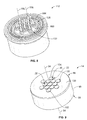
- Figure 1 is a perspective view illustrating a cross-section of an exemplary embodiment of a connector system
- Figure 2 is a perspective view of an exemplary embodiment of an electrical connector of the connector system shown in Figure 1 ;
- Figure 3 is an exploded perspective view of the electrical connector shown in Figure 2 ;
- Figure 4 is a perspective view illustrating a cross-section of the electrical connector shown in Figures 2 and 3 ;
- Figure 5 is another perspective view of a cross-section of the electrical connector shown in Figures 2-4 illustrating exemplary embodiments of electrical contacts in exemplary embodiments of retracted positions;
- Figure 6 is a perspective view of the electrical connector shown in Figures 2-5 illustrating an exemplary embodiment of a hood in an exemplary embodiment of a retracted position;
- Figure 7 is a perspective view of a cross-section of the electrical connector shown in Figures 2-6 illustrating both the electrical contacts and the hood in the exemplary embodiments of the retracted positions;
- Figure 8 is a perspective view of another exemplary embodiment of an electrical connector
- Figure 9 is a perspective view of an exemplary embodiment of another electrical connector of the connector system shown in Figure 1 ;
- Figure 10 is a side elevational view of an exemplary embodiment of a weapon with which the connector system shown in Figure 1 may be used;
- Figure 11 is a side elevational view of the weapon shown in Figure 10 illustrating the weapon in an open state.
- an electrical connector in one embodiment, includes a housing having an internal compartment.
- a dielectric insert is held within the internal compartment of the housing.
- the dielectric insert includes an end face.
- An electrical contact is held by the dielectric insert and includes a mating segment that extends a length outwardly from the end face of the dielectric insert along a connection axis.
- a hood is held by the housing and has an extended position relative to the end face of the dielectric insert wherein the hood extends a length outwardly relative to the end face.
- the hood extends at least partially around the mating segment of the electrical contact in the extended position.
- the hood is retractable along the connection axis from the extended position to a retracted position wherein at least a portion of the length of the hood is retracted relative to the end face of the dielectric insert.
- a weapon in another embodiment, includes a base having a lower receiver.
- the base houses electronics therein.
- the weapon also includes an upper part having an upper receiver that is removably attachable to the lower receiver.
- the upper part houses electronics therein.
- the weapon also includes a communication connector system communicatively connecting the electronics of the base with the electronics of the upper part.
- the communication connector system includes upper and lower connectors coupled to the upper and lower receivers, respectively.
- the upper and lower connectors are communicatively connected to the electronics in the upper part and the base, respectively.
- the upper connector and/or the lower connector includes a housing having an internal compartment, a dielectric insert held within the internal compartment of the housing, and an electrical contact held by the dielectric insert.
- the electrical contact includes a mating segment that extends a length outwardly from the dielectric insert.
- a hood is held by the housing.
- the hood has an extended position relative to the dielectric insert.
- the hood extends at least partially around the mating segment of the electrical contact in the extended position.
- the hood is retractable from the extended position to a retracted position wherein at least a portion of the length of the hood is retracted relative to the dielectric insert.
- an electrical connector in another embodiment, includes a housing having an internal compartment, and a dielectric insert held within the internal compartment of the housing.
- the dielectric insert includes an end face.
- An electrical contact is held by the dielectric insert.
- the electrical contact includes a mating segment that extends a length outwardly from the end face of the dielectric insert along a connection axis. The mating segment is retractable along the connection axis in a direction generally toward the dielectric insert.
- a hood is held by the housing.
- the hood has an extended position relative to the end face of the dielectric insert wherein the hood extends a length outwardly relative to the end face.
- the hood extends at least partially around the mating segment of the electrical contact in the extended position.
- the hood is retractable along the connection axis from the extended position to a retracted position wherein at least a portion of the length of the hood is retracted relative to the end face of the dielectric insert.
- Figure 1 is a perspective view illustrating a cross-section of an exemplary embodiment of a connector system 10.
- the connector system includes a pair of electrical connectors 12 and 14 that mate together to establish an electrical connection therebetween.
- Each of the electrical connectors 12 and 14 includes a respective housing 16 and 18 that holds one or more electrical contacts 20 and 22, respectively.
- mating segments 24 of the electrical contacts 20 engage mating segments 26 of the electrical contacts 22 to electrically interconnect the electrical connectors 12 and 14.
- the electrical connector 12 and/or the electrical connector 14 may include a retractable hood 28 that is retractable from an extended position wherein the hood extends at least partially around the mating segments 24 and/or 26, respectively, of the electrical contacts 20 and/or 22, respectively.
- the mating segments 24 and/or 26 of the electrical contacts 20 and/or 22, respectively may be retractable.
- the connector system 10 may be used to interconnect a wide variety of electrical components.
- the connector system 10 may be used as a component of a weapon (e.g. the weapon 200 shown in Figures 10 and 11 ) for interconnect various electrical components of the weapon.
- the connector system 10 is not limited to being used with weapons. Rather, the connector system 10 may be used to interconnect any electrical components and may be used as a component of any other device, structure, machine, component, and/or the like besides a weapon.
- Each of the electrical connectors 12 and 14 may be referred to herein as a "mating connector".
- FIG 2 is a perspective view of an exemplary embodiment of the electrical connector 12.
- Figure 3 is an exploded perspective view of the electrical connector 12.
- Figure 4 is a perspective view illustrating a cross-section of the electrical connector 12.
- the electrical connector 12 extends along a central longitudinal axis 30 and includes the housing 16, a dielectric insert 32, the electrical contacts 20, and the hood 28.
- the housing 16 extends a length along the central longitudinal axis 30 from an end 34 to an opposite end 36.
- the housing 16 includes an internal compartment 38 that, in the exemplary embodiment, extends through the length of the housing 16.
- the end 34 of the housing 16 includes a mating face 40 that faces the housing 18 ( Figures 1 and 9 ) of the electrical connector 14 ( Figures 1 and 9 ) when the electrical connectors 12 and 14 are mated together.
- the mating face 40 optionally includes a groove 42 that is configured to receive an optional seal 44.
- the dielectric insert 32 is held within the internal compartment 38 of the housing 16.
- the dielectric insert 32 includes a dielectric body that extends a length along the central longitudinal axis 30 from an end 46 to an opposite end 48.
- the end 46 includes an end face 50.
- the end 48 of the body of the dielectric insert 32 includes a flange 52 that extends radially outwardly relative to the central longitudinal axis 30.
- One or more contact openings 54 extend through the length of the body of the dielectric insert 32.
- the contact openings 54 are configured to hold corresponding electrical contacts 20 of the electrical connector 12 therein.
- the body of the dielectric insert 32 may include any number of the contact openings 54 for holding any number of electrical contacts 20.
- the electrical contacts 20 of the electrical connector 12 are held by the dielectric insert 32. Specifically, the electrical contacts 20 are held within the contact openings 54 of the body of the dielectric insert 32. Each electrical contact 20 includes the mating segment 24. The electrical contacts 20 are held within the contact openings 54. When the mating segment 24 of an electrical contact 20 is in an extended position (e.g. as shown in Figures 2-4 ), the mating segment 24 extends a length outwardly from the end face 50 of the dielectric insert 32 along a corresponding connection axis 56.
- the connection axes 56 may extend approximately parallel to the central longitudinal axis 30 of the electrical connector 12, as is shown in the exemplary embodiment.
- Each electrical contact 20 may be a signal contact, a ground contact, or an electrical power contact. Although thirteen are shown, the electrical connector 12 may include any number of the electrical contacts 20.
- the mating segment 24 of each electrical contact 20 is a pin. However, each mating segment 24 may additionally or alternatively include any other structure, type of contact, and/or the like, such as, but not limited to, a spring, a receptacle, an arm, a tab, a pad, and/or the like.
- each electrical contact 20 includes an intermediate segment 58 that extends within the corresponding contact opening 54.
- the intermediate segments 58 optionally include one or more retention features 60 that facilitate holding the intermediate segments 58 within the contact openings 54, for example with a snap or interference fit connection.
- the intermediate segments 58 extend lengths from ends 62 to opposite ends 64.
- each electrical contact 20 includes a termination segment 66.
- the termination segment 66 is configured to be electrically connected to an electrical component, such as, but not limited to, an electrical wire, an electrical cable, another electrical contact, a circuit board, an electrical device, and/or the like.
- the termination segments 66 extend along the end 36 of the housing 16.
- one or more of the mating segments 24 of the electrical contacts 20 is retractable from the extended position.
- each of the mating segments 24 is retractable from the extended position.
- one or more of the mating segments 24 is not retractable from the extended position.
- none of the mating segments 24 are retractable from the extended position. As shown in Figures 2-4 , each of the mating segments 24 is in the extended position.
- the mating segments 24 are retractable from the extended position along the connection axes 56.
- Each mating segment 24 is retractable along the corresponding connection axis 56 in a direction generally toward the dielectric insert 32, which is represented by the arrow A in Figure 4 .
- a tip 68 of the mating segment 24 moves along the connection axis 56 in a direction generally toward the dielectric insert 32.
- Figure 5 is another perspective view of a cross-section of the electrical connector 12 the mating segments 24 of the electrical contacts 20 in exemplary embodiments of retracted positions.
- the mating segments 24 have moved along the connection axes 56 in the direction A from the extended positions shown in Figure 4 to the retracted positions shown in Figure 5 .
- the tip 68 of the mating segment 24 is aligned along the axis 56 with, or spaced apart along the axis 56 in the direction A from, an end face 70 of the corresponding intermediate segment 58. But, in other embodiments of the retracted position, the tip 68 is spaced apart from the end face 70 along the connection axis 56 in the direction of the arrow B.
- the tip 68 of the mating segment 24 is aligned along the axis 56 with, or spaced apart along the axis 56 in the direction of the arrow A from, the end face 50 of the dielectric insert 32. In some embodiments of the retracted position, the tip 68 of the mating segment 24 is aligned along the axis 56 with, or spaced apart along the axis 56 in the direction of the arrow A from, the mating face 40 of the housing 16.
- the end 62 of the intermediate segment 58 extends outwardly from the end face 50 of the dielectric insert 32.
- the end face 70 of the intermediate segment 58 is spaced apart from the end face 50 along the corresponding connection axis 56 in the direction of the arrow B.
- the end face 70 is aligned along the axis 56 with, or spaced apart along the axis 56 in the direction A from, the end face 50.
- the mating segments 24 of the electrical contacts 24 move between the extended and retracted positions by being slidably received within interior compartments 72 of the corresponding intermediate segments 58.
- the mating segment 24 may include an interior cavity (not shown) that is configured to receive the corresponding intermediate segment 58 at least partially therein such that the mating segment 24 is configured to slide over the intermediate segment 58 between the extended and retracted positions.
- the electrical connector 12 optionally includes one or more biasing mechanisms 74 that are configured to bias, or urge, the mating segments 24 to the extended positions.
- the mating segments 24 are movable from the extended positions to the retracted positions against the bias provided by the biasing mechanisms 74.
- the retracted positions of the mating segments 24 may be at the end of a range of travel of the biasing mechanisms 74.
- a stop or other structure may be provided for limiting the range of movement of the mating segments 24 along the axes 56 in the direction of the arrow A.
- the biasing mechanisms 74 are held within the interior compartments 72 between the mating segments 24 and shoulders 76 of the intermediate segments 58. But, any other suitable arrangement that enables the biasing mechanisms 74 to function as described and/or illustrated herein may be provided. Although the biasing mechanisms 74 are illustrated as coil springs, each biasing mechanism 74 may additionally or alternatively include any other type of biasing mechanism, such as, but not limited to, leaf springs, wave springs, spring arms, spring tabs, and/or the like.
- the hood 28 is held by the housing 16.
- the hood 28 includes a base 78 (not visible in Figure 2 ) and one or more walls 80 that extend outwardly from the base 78 along the central longitudinal axis 30.
- the hood 28 extends a length along the central longitudinal axis 30 from the base 78 to an end 82 of the wall 80.
- the end 82 of the wall 80 includes a tip 84.
- the base 78 may include a flange 86 (not visible in Figure 2 ) that extends radially outward relative to the central longitudinal axis 30.
- the hood 28 may include any number of walls 80.
- the hood 28 is held by the housing 16 such that, when the hood 28 is in an extended position (e.g. as shown in Figures 2 and 4 ), the hood 28 extends a length outwardly relative to the end face 50 of the dielectric insert 32 and relative to the mating face 40 of the housing 16.
- the tip 84 of the hood 28 is spaced apart from the end face 50 and the mating face 40 along the central longitudinal axis 30 in the direction of the arrow B.
- the wall 80 of the hood 28 extends at least partially around the mating segments 24.
- the length of the hood 28 from the base 78 to the tip 84 defines a cavity 88 within which the lengths of the mating segments 24 extend when the hood 28 and the mating segments 24 are in the extended positions.
- the wall 80 is a continuous wall that extends around an approximate entirety of the circumference of the mating segments 24 when the hood 28 is in the extended position.
- the wall 80 of the hood 28 may alternatively extend around only one or more portions of the circumference of the mating segments 24, whether or not the wall 80 is composed of a single wall or two or more walls wherein adjacent walls may and/or may not be interconnected.
- the tip 84 of the hood 28 is spaced apart along the axis 30 from the tips 68 of the mating segments 24 in the direction of the arrow B when the hood 28 and the mating segments 24 are in the extended positions.
- one or more of the tips 68 is aligned along the axis 30 with, and/or spaced apart along the axis 30 in the direction of the arrow B from, the tip 84 when the hood 28 and the mating segments 24 are in the extended positions.
- the hood 28 is configured to move, or slide, along the connection axes 56 between the extended position and a retracted position. Specifically, the hood 28 is retractable along the connection axes 56 from the extended position to a retracted position wherein at least a portion of the length of the hood 28 is retracted relative to the end face 50 of the dielectric insert 32. As shown in Figures 2-5 , the hood 28 is in the extended position.
- the hood 28 is retractable along the connection axes 56 in the direction A, which is generally toward the dielectric insert 32. In other words, as the hood 28 retracts from the extended position toward the retracted position, the tip 84 of the hood 28 moves along the connection axes 56 in a direction generally toward the dielectric insert 32.
- Figure 6 is a perspective view of the electrical connector 12 illustrating the hood 28 in an exemplary embodiment of a retracted position.
- Figure 7 is a perspective view of a cross-section of the electrical connector 12 illustrating both the hood 28 and the mating segments 24 of the electrical contacts 20 in the exemplary embodiments of the retracted positions. The mating segments 24 of the electrical contacts 20 are shown in the extended positions in Figure 6 .
- the hood 28 has moved along the connection axes 56 in the direction A from the extended position shown in Figure 4 to the retracted position shown in Figures 6 and 7 .
- the tip 84 of the hood 28 In the retracted position, the tip 84 of the hood 28 is aligned along the axes 56 with the mating face 40 of the housing 16. But, in other embodiments of the retracted position, the tip 84 of the hood 28 is spaced apart from the mating face 40 along the connection axes 56 in the direction of the arrow B or is spaced apart from the mating face 40 along the axes 56 in the direction A. In the exemplary embodiment of the retracted position, the tip 84 of the hood 28 is spaced apart along the axes 56 in the direction of the arrow B from the end face 50 of the dielectric insert 32.
- Figure 8 is a perspective view of another exemplary embodiment of an electrical connector 112 having a hood 128 that is moveable between an extended position (not shown) and a retracted position (shown in Figure 8 ).
- a tip 184 of the hood 128 is aligned along connection axes 156 with an end face 150 of a dielectric insert 132 of the electrical connector 112.
- the tip 84 of the hood 28 is spaced apart along the axes 56 in the direction A from the tips 68 of the mating segments 24 of the electrical contacts 20 when the mating segments 24 are in the extended positions. But, in other embodiments of the retracted position, the tip 84 of the hood 28 is aligned with along the axes 56, or is spaced apart along the axes 56 in the direction B from, the tips 68 of the mating segments 24 when the mating segments 24 are in the extended positions.
- the tip 84 of the hood 28 is spaced apart along the axes 56 in the direction B from the tips 68 of the mating segments 24 of the electrical contacts 20 when the mating segments 24 are in the retracted positions. But, in other embodiments of the retracted position, the tip 84 of the hood 28 is aligned with along the axes 56 with, or is spaced apart along the axes 56 in the direction A from, the tips 68 of the mating segments 24 when the mating segments 24 are in the retracted positions.
- the hood 28 moves between the extended and retracted positions by being slidably received within the interior compartment 38 of the housing 16 between the dielectric insert 32 and the housing 16.
- any other suitable arrangement that enables the hood 28 to move between the extended and retracted positions may be provided.
- the flange 86 of the hood 28 may engage a shoulder 90 of the housing 16 when the hood 28 is in the extended position to limit the range of movement of the hood 28 in the direction of the arrow B.
- the electrical connector 12 optionally includes one or more biasing mechanisms 92 (also shown in Figure 3 ) that are configured to bias, or urge, the hood 28 to the extended position.
- the hood 28 is movable from the extended position to the retracted position against the bias provided by the biasing mechanism 92.
- the retracted position of the hood 28 may be at the end of a range of travel of the biasing mechanism 92.
- a stop or other structure may be provided for limiting the range of movement of the hood 28 in the direction of the arrow A.
- the biasing mechanism 92 is held within the interior compartment 38 of the housing 16 between the flange 52 of the dielectric insert 32 and the flange 86 of the hood 28.
- biasing mechanism 92 may additionally or alternatively include any other type of biasing mechanism, such as, but not limited to, leaf springs, coils springs, spring arms, spring tabs, and/or the like.
- the retracted position of the hood 28 and/or the retracted positions of the mating segments 24 of the electrical contacts 20 may enable the electrical connector 12 to be more easily cleaned without damaging the electrical contacts 20.
- the hood 28 can be retracted to expose the mating segments 24 in the extended positions of the mating segments 24. Mud, sand, dirt, dust, and/or other debris may then be removed from between the mating segments 24, for example using a person's hand, water, air, cleaning fluid, and/or the like.
- the mating segments 24 of the electrical contacts 20 can be retracted, as is shown in Figure 7 . With the mating segments 24 retracted, for example as shown in Figure 7 , any mud, sand, dirt, dust, and/or other debris that has accumulated between the mating segments 24 can be removed by cleaning the end face 50 of the dielectric insert 32.
- FIG 9 is a perspective view of an exemplary embodiment of the electrical connector 14.
- the electrical connector 14 includes the housing 18 and the electrical contacts 22.
- the housing 18 extends a length along a central longitudinal axis 94 from an end 96 to an opposite end 98.
- the end 96 of the housing 18 includes a mating face 100 that faces the housing 16 ( Figures 1-7 ) of the electrical connector 12 ( Figures 1-7 ) when the electrical connectors 12 and 14 are mated together.
- One or more contact openings 102 extend through the length of the housing 18.
- the contact openings 102 are configured to hold corresponding electrical contacts 22 of the electrical connector 14 therein.
- the housing 18 may include any number of the contact openings 102 for holding any number of electrical contacts 22.
- the electrical contacts 22 of the electrical connector 14 are held within the contact openings 102 of the housing 18.
- Each electrical contact 22 includes the mating segment 26.
- tips 104 of the mating segments 26 are aligned along the central longitudinal axis 94 with the mating face 100 of the housing 18. But, in other embodiments, one or more of the tips 104 of the mating segments 26 extends a length outwardly from the mating face 100 of the housing 18 and/or is recessed relative to the mating face 100.
- Each electrical contact 22 may be a signal contact, a ground contact, or an electrical power contact. Although thirteen are shown, the electrical connector 14 may include any number of the electrical contacts 22.
- the mating segment 26 of each electrical contact 22 is a pad. However, each mating segment 26 may additionally or alternatively include any other structure, type of contact, and/or the like, such as, but not limited to, a pin, a spring, a receptacle, an arm, a tab, and/or the like.
- each electrical contact 22 includes an intermediate segment 106 that extends within the corresponding contact opening 102.
- the intermediate segments 106 optionally include one or more retention features (not shown) that facilitate holding the intermediate segments 106 within the contact openings 102, for example with a snap or interference fit connection.
- Each electrical contact 22 includes a termination segment 108.
- the termination segment 108 is configured to be electrically connected to an electrical component, such as, but not limited to, an electrical wire, an electrical cable, another electrical contact, a circuit board, an electrical device, and/or the like.
- the mating segments 24 of the electrical contacts 20 engage the mating segments 26 of the electrical contacts 22 to electrically interconnect the electrical connectors 12 and 14.
- the mating face 100 of the housing 18 of the electrical connector 14 is engaged with the seal 44 and/or the mating face 40 of the housing 16 of the electrical connector 12 when the connectors 12 and 14 are mated together.
- the hood 28 is optionally configured to retract from the extended position toward the retracted position during mating of the electrical connector 12 with the electrical connector 14, for example via engagement with the electrical connector 14.
- the mating segments 24 of the electrical contacts are optionally configured to retract from the extended positions toward the retracted positions during mating of the electrical connectors 12 and 14, for example via engagement with the electrical contacts 22.
- each of the electrical connectors 12 and 14, and each of any individual components thereof, may additionally or alternatively include any other shape.
- Figure 10 is a side elevational view of an exemplary embodiment of a weapon 200 with which the connector system 10 may be used.
- the weapon 200 is illustrated in a closed state in Figure 10.
- Figure 11 is a side elevational view of the weapon 200 in an open state.
- the weapon 200 is an AR-15 style weapon.
- the weapon 200 is not limited to AR-15 style weapons. Rather, the weapon 200 may be any other type of weapon with which an electrical connector may be used.
- the weapon 200 is of a type that includes a rail 202 having electronics 203 therein and a lower part, or base, 207 having electronics 205 therein.
- the weapon 200 includes an upper part 209 that is coupled to the base 207.
- the upper part 109 includes the rail 202, a barrel 210, and an upper receiver 214.
- the base 207 includes a hand grip 204, a lower receiver 216 and a butt stock 212.
- the electronics 205 may be housed in any of the hand grip 204, the lower receiver 216 and/or the butt stock 212.
- the base 207 may include other components of the weapon 200.
- the upper part 109 may include other components of the weapon 200.
- the weapon 200 includes the connector system 10, which electrically connects the electronics 205 of the base 207 with the electronics 203 associated with the rail 202.
- the communication connector system 10 transmits electrical power and/or electrical data between the rail 202 and the base 207.
- the connector system 10 includes the electrical connectors 12 and 14 ( Figures 1-7 and 9 and Figures 1 and 9 , respectively), which are easily and repeatedly mated and unmated as the weapon 200 is moved between the closed state (shown in Figure 10 ) and the open state (shown in Figure 11 ).
- the base 207 may include the electrical connector 12, while the upper part 209 includes the electrical connector 14. In other embodiments, the base 207 includes the electrical connector 14 and the upper part 209 includes the electrical connector 12.
- the connector system 10 may also include an external connector (not shown) for interfacing with an external connector, such as an electrical connector and/or fiber optic connector provided at an end of cable extending from the user of the weapon 200. Data and/or power may be transmitted to and/or from the user and the weapon 200 via the external connector.
- the communication connector system 10 connectorizes the interface between the base 207 and the rail 202.
Landscapes
- Engineering & Computer Science (AREA)
- General Engineering & Computer Science (AREA)
- Connector Housings Or Holding Contact Members (AREA)
- Details Of Connecting Devices For Male And Female Coupling (AREA)
Abstract
Description
- The subject matter herein relates generally to electrical connectors.
- Weapons, such as AR-15s, M4's, M-16's, and others, include a rail having electronics mounted to or within the upper rail. The upper rail may include a laser, night vision scope, camera or other type of electronic that needs power. The electronics may also send or receive data. The weapons typically include electronics, including batteries, in the lower part of the weapon, such as in the butt stock, hand grip, lower receiver, which are communicatively connected to the electronics in the upper rail.
- Connecting the electronics in the lower part of the weapon with the electronics in the upper rail has heretofore proven difficult. Some systems use wires along the outside of the gun that interconnect the electronics in the lower part of the weapon with the electronics in the upper rail. The wires tend to catch or snag or are exposed to be easily damaged, which is problematic. Other systems route wires internally. However, the upper and lower receivers need to be completely redesigned, and thus are not compatible with existing parts. Additionally, the weapons are often disassembled, such as for cleaning, and having the internal wiring makes disassembly difficult.
- At least some known weapons include connector systems for connecting the electronics in the upper and lower parts of the weapon. Specifically, the upper and lower parts may be provided with electrical connectors that, when mated together, establish an electrical connection between the electronics in the upper and lower parts of the weapon. But, known connector systems are not without disadvantages. Mud, sand, dirt, dust, and/or other debris may infiltrate the electrical connectors, for example during use of the weapon within the field and/or during disassembly, cleaning, and/or repair of the weapon. Such debris may inhibit operation of the electrical connectors. But, it may be difficult to clean the debris from the electrical connectors without damaging the electrical contacts of the electrical connectors.
- The solution is provided by an electrical connector that includes a housing having an internal compartment. A dielectric insert is held within the internal compartment of the housing. The dielectric insert includes an end face. An electrical contact is held by the dielectric insert and includes a mating segment that extends a length outwardly from the end face of the dielectric insert along a connection axis. A hood is held by the housing and has an extended position relative to the end face of the dielectric insert wherein the hood extends a length outwardly relative to the end face. The hood extends at least partially around the mating segment of the electrical contact in the extended position. The hood is retractable along the connection axis from the extended position to a retracted position wherein at least a portion of the length of the hood is retracted relative to the end face of the dielectric insert.
- The invention will now be described by way of example with reference to the accompanying drawings in which:
-
Figure 1 is a perspective view illustrating a cross-section of an exemplary embodiment of a connector system; -
Figure 2 is a perspective view of an exemplary embodiment of an electrical connector of the connector system shown inFigure 1 ; -
Figure 3 is an exploded perspective view of the electrical connector shown inFigure 2 ; -
Figure 4 is a perspective view illustrating a cross-section of the electrical connector shown inFigures 2 and3 ; -
Figure 5 is another perspective view of a cross-section of the electrical connector shown inFigures 2-4 illustrating exemplary embodiments of electrical contacts in exemplary embodiments of retracted positions; -
Figure 6 is a perspective view of the electrical connector shown inFigures 2-5 illustrating an exemplary embodiment of a hood in an exemplary embodiment of a retracted position; -
Figure 7 is a perspective view of a cross-section of the electrical connector shown inFigures 2-6 illustrating both the electrical contacts and the hood in the exemplary embodiments of the retracted positions; -
Figure 8 is a perspective view of another exemplary embodiment of an electrical connector; -
Figure 9 is a perspective view of an exemplary embodiment of another electrical connector of the connector system shown inFigure 1 ; -
Figure 10 is a side elevational view of an exemplary embodiment of a weapon with which the connector system shown inFigure 1 may be used; and -
Figure 11 is a side elevational view of the weapon shown inFigure 10 illustrating the weapon in an open state. - In one embodiment, an electrical connector includes a housing having an internal compartment. A dielectric insert is held within the internal compartment of the housing. The dielectric insert includes an end face. An electrical contact is held by the dielectric insert and includes a mating segment that extends a length outwardly from the end face of the dielectric insert along a connection axis. A hood is held by the housing and has an extended position relative to the end face of the dielectric insert wherein the hood extends a length outwardly relative to the end face. The hood extends at least partially around the mating segment of the electrical contact in the extended position. The hood is retractable along the connection axis from the extended position to a retracted position wherein at least a portion of the length of the hood is retracted relative to the end face of the dielectric insert.
- In another embodiment, a weapon includes a base having a lower receiver. The base houses electronics therein. The weapon also includes an upper part having an upper receiver that is removably attachable to the lower receiver. The upper part houses electronics therein. The weapon also includes a communication connector system communicatively connecting the electronics of the base with the electronics of the upper part. The communication connector system includes upper and lower connectors coupled to the upper and lower receivers, respectively. The upper and lower connectors are communicatively connected to the electronics in the upper part and the base, respectively. The upper connector and/or the lower connector includes a housing having an internal compartment, a dielectric insert held within the internal compartment of the housing, and an electrical contact held by the dielectric insert. The electrical contact includes a mating segment that extends a length outwardly from the dielectric insert. A hood is held by the housing. The hood has an extended position relative to the dielectric insert. The hood extends at least partially around the mating segment of the electrical contact in the extended position. The hood is retractable from the extended position to a retracted position wherein at least a portion of the length of the hood is retracted relative to the dielectric insert.
- In another embodiment, an electrical connector includes a housing having an internal compartment, and a dielectric insert held within the internal compartment of the housing. The dielectric insert includes an end face. An electrical contact is held by the dielectric insert. The electrical contact includes a mating segment that extends a length outwardly from the end face of the dielectric insert along a connection axis. The mating segment is retractable along the connection axis in a direction generally toward the dielectric insert. A hood is held by the housing. The hood has an extended position relative to the end face of the dielectric insert wherein the hood extends a length outwardly relative to the end face. The hood extends at least partially around the mating segment of the electrical contact in the extended position. The hood is retractable along the connection axis from the extended position to a retracted position wherein at least a portion of the length of the hood is retracted relative to the end face of the dielectric insert.
-
Figure 1 is a perspective view illustrating a cross-section of an exemplary embodiment of aconnector system 10. The connector system includes a pair ofelectrical connectors electrical connectors respective housing electrical contacts electrical connectors mating segments 24 of theelectrical contacts 20 engagemating segments 26 of theelectrical contacts 22 to electrically interconnect theelectrical connectors - As will be described below, the
electrical connector 12 and/or theelectrical connector 14 may include aretractable hood 28 that is retractable from an extended position wherein the hood extends at least partially around themating segments 24 and/or 26, respectively, of theelectrical contacts 20 and/or 22, respectively. As will also be described below, themating segments 24 and/or 26 of theelectrical contacts 20 and/or 22, respectively, may be retractable. - The
connector system 10 may be used to interconnect a wide variety of electrical components. For example, theconnector system 10 may be used as a component of a weapon (e.g. theweapon 200 shown inFigures 10 and 11 ) for interconnect various electrical components of the weapon. But, theconnector system 10 is not limited to being used with weapons. Rather, theconnector system 10 may be used to interconnect any electrical components and may be used as a component of any other device, structure, machine, component, and/or the like besides a weapon. Each of theelectrical connectors -
Figure 2 is a perspective view of an exemplary embodiment of theelectrical connector 12.Figure 3 is an exploded perspective view of theelectrical connector 12.Figure 4 is a perspective view illustrating a cross-section of theelectrical connector 12. Referring now toFigures 2-4 , theelectrical connector 12 extends along a centrallongitudinal axis 30 and includes thehousing 16, adielectric insert 32, theelectrical contacts 20, and thehood 28. Thehousing 16 extends a length along the centrallongitudinal axis 30 from anend 34 to anopposite end 36. Thehousing 16 includes aninternal compartment 38 that, in the exemplary embodiment, extends through the length of thehousing 16. Theend 34 of thehousing 16 includes amating face 40 that faces the housing 18 (Figures 1 and9 ) of the electrical connector 14 (Figures 1 and9 ) when theelectrical connectors mating face 40 optionally includes agroove 42 that is configured to receive anoptional seal 44. - The
dielectric insert 32 is held within theinternal compartment 38 of thehousing 16. Referring now toFigures 3 and4 , thedielectric insert 32 includes a dielectric body that extends a length along the centrallongitudinal axis 30 from anend 46 to anopposite end 48. Theend 46 includes anend face 50. In the exemplary embodiment, theend 48 of the body of thedielectric insert 32 includes aflange 52 that extends radially outwardly relative to the centrallongitudinal axis 30. - One or
more contact openings 54 extend through the length of the body of thedielectric insert 32. Thecontact openings 54 are configured to hold correspondingelectrical contacts 20 of theelectrical connector 12 therein. The body of thedielectric insert 32 may include any number of thecontact openings 54 for holding any number ofelectrical contacts 20. - The
electrical contacts 20 of theelectrical connector 12 are held by thedielectric insert 32. Specifically, theelectrical contacts 20 are held within thecontact openings 54 of the body of thedielectric insert 32. Eachelectrical contact 20 includes themating segment 24. Theelectrical contacts 20 are held within thecontact openings 54. When themating segment 24 of anelectrical contact 20 is in an extended position (e.g. as shown inFigures 2-4 ), themating segment 24 extends a length outwardly from theend face 50 of thedielectric insert 32 along acorresponding connection axis 56. The connection axes 56 may extend approximately parallel to the centrallongitudinal axis 30 of theelectrical connector 12, as is shown in the exemplary embodiment. - Each
electrical contact 20 may be a signal contact, a ground contact, or an electrical power contact. Although thirteen are shown, theelectrical connector 12 may include any number of theelectrical contacts 20. In the exemplary embodiment, themating segment 24 of eachelectrical contact 20 is a pin. However, eachmating segment 24 may additionally or alternatively include any other structure, type of contact, and/or the like, such as, but not limited to, a spring, a receptacle, an arm, a tab, a pad, and/or the like. - Referring now to
Figure 4 , eachelectrical contact 20 includes anintermediate segment 58 that extends within thecorresponding contact opening 54. Theintermediate segments 58 optionally include one or more retention features 60 that facilitate holding theintermediate segments 58 within thecontact openings 54, for example with a snap or interference fit connection. Theintermediate segments 58 extend lengths from ends 62 to opposite ends 64. - At the
end 64, eachelectrical contact 20 includes atermination segment 66. Thetermination segment 66 is configured to be electrically connected to an electrical component, such as, but not limited to, an electrical wire, an electrical cable, another electrical contact, a circuit board, an electrical device, and/or the like. In the exemplary embodiment, thetermination segments 66 extend along theend 36 of thehousing 16. - Optionally, one or more of the
mating segments 24 of theelectrical contacts 20 is retractable from the extended position. In the exemplary embodiment, each of themating segments 24 is retractable from the extended position. However, in other embodiments one or more of themating segments 24 is not retractable from the extended position. In some embodiments, none of themating segments 24 are retractable from the extended position. As shown inFigures 2-4 , each of themating segments 24 is in the extended position. - In the exemplary embodiment, the
mating segments 24 are retractable from the extended position along the connection axes 56. Eachmating segment 24 is retractable along thecorresponding connection axis 56 in a direction generally toward thedielectric insert 32, which is represented by the arrow A inFigure 4 . In other words, as themating segment 24 retracts along theconnection axis 56, atip 68 of themating segment 24 moves along theconnection axis 56 in a direction generally toward thedielectric insert 32. -
Figure 5 is another perspective view of a cross-section of theelectrical connector 12 themating segments 24 of theelectrical contacts 20 in exemplary embodiments of retracted positions. Themating segments 24 have moved along the connection axes 56 in the direction A from the extended positions shown inFigure 4 to the retracted positions shown inFigure 5 . In the retracted position, thetip 68 of themating segment 24 is aligned along theaxis 56 with, or spaced apart along theaxis 56 in the direction A from, anend face 70 of the correspondingintermediate segment 58. But, in other embodiments of the retracted position, thetip 68 is spaced apart from theend face 70 along theconnection axis 56 in the direction of the arrow B. In some embodiments of the retracted position, thetip 68 of themating segment 24 is aligned along theaxis 56 with, or spaced apart along theaxis 56 in the direction of the arrow A from, theend face 50 of thedielectric insert 32. In some embodiments of the retracted position, thetip 68 of themating segment 24 is aligned along theaxis 56 with, or spaced apart along theaxis 56 in the direction of the arrow A from, themating face 40 of thehousing 16. - As can be seen in
Figure 5 , in the exemplary embodiment, theend 62 of theintermediate segment 58 extends outwardly from theend face 50 of thedielectric insert 32. In other words, theend face 70 of theintermediate segment 58 is spaced apart from theend face 50 along thecorresponding connection axis 56 in the direction of the arrow B. But, in other embodiments, theend face 70 is aligned along theaxis 56 with, or spaced apart along theaxis 56 in the direction A from, theend face 50. - Referring now to
Figures 4 and5 , in the exemplary embodiment, themating segments 24 of theelectrical contacts 24 move between the extended and retracted positions by being slidably received withininterior compartments 72 of the correspondingintermediate segments 58. But, any other suitable arrangement that enables themating segments 24 to move between the extended and retracted positions may be provided. For example, themating segment 24 may include an interior cavity (not shown) that is configured to receive the correspondingintermediate segment 58 at least partially therein such that themating segment 24 is configured to slide over theintermediate segment 58 between the extended and retracted positions. - The
electrical connector 12 optionally includes one ormore biasing mechanisms 74 that are configured to bias, or urge, themating segments 24 to the extended positions. Themating segments 24 are movable from the extended positions to the retracted positions against the bias provided by the biasingmechanisms 74. The retracted positions of themating segments 24 may be at the end of a range of travel of the biasingmechanisms 74. Additionally or alternatively, a stop or other structure (not shown) may be provided for limiting the range of movement of themating segments 24 along theaxes 56 in the direction of the arrow A. - In the exemplary embodiment, the biasing
mechanisms 74 are held within the interior compartments 72 between themating segments 24 andshoulders 76 of theintermediate segments 58. But, any other suitable arrangement that enables the biasingmechanisms 74 to function as described and/or illustrated herein may be provided. Although the biasingmechanisms 74 are illustrated as coil springs, each biasingmechanism 74 may additionally or alternatively include any other type of biasing mechanism, such as, but not limited to, leaf springs, wave springs, spring arms, spring tabs, and/or the like. - Referring again to
Figures 2 and3 , thehood 28 is held by thehousing 16. Thehood 28 includes a base 78 (not visible inFigure 2 ) and one ormore walls 80 that extend outwardly from thebase 78 along the centrallongitudinal axis 30. Thehood 28 extends a length along the centrallongitudinal axis 30 from the base 78 to anend 82 of thewall 80. Theend 82 of thewall 80 includes atip 84. The base 78 may include a flange 86 (not visible inFigure 2 ) that extends radially outward relative to the centrallongitudinal axis 30. Although only onewall 80 is shown herein, thehood 28 may include any number ofwalls 80. - Referring now to
Figures 2 and4 , thehood 28 is held by thehousing 16 such that, when thehood 28 is in an extended position (e.g. as shown inFigures 2 and4 ), thehood 28 extends a length outwardly relative to theend face 50 of thedielectric insert 32 and relative to themating face 40 of thehousing 16. In other words, when thehood 28 is in the extended position, thetip 84 of thehood 28 is spaced apart from theend face 50 and themating face 40 along the centrallongitudinal axis 30 in the direction of the arrow B. When thehood 28 is in the extended position and themating segments 24 of theelectrical contacts 20 are in the extended positions, thewall 80 of thehood 28 extends at least partially around themating segments 24. In other words, the length of thehood 28 from the base 78 to thetip 84 defines acavity 88 within which the lengths of themating segments 24 extend when thehood 28 and themating segments 24 are in the extended positions. In the exemplary embodiment, thewall 80 is a continuous wall that extends around an approximate entirety of the circumference of themating segments 24 when thehood 28 is in the extended position. But, thewall 80 of thehood 28 may alternatively extend around only one or more portions of the circumference of themating segments 24, whether or not thewall 80 is composed of a single wall or two or more walls wherein adjacent walls may and/or may not be interconnected. - Referring now solely to
Figure 4 , in the exemplary embodiment, thetip 84 of thehood 28 is spaced apart along theaxis 30 from thetips 68 of themating segments 24 in the direction of the arrow B when thehood 28 and themating segments 24 are in the extended positions. In some other embodiments, one or more of thetips 68 is aligned along theaxis 30 with, and/or spaced apart along theaxis 30 in the direction of the arrow B from, thetip 84 when thehood 28 and themating segments 24 are in the extended positions. - Optionally, the
hood 28 is configured to move, or slide, along the connection axes 56 between the extended position and a retracted position. Specifically, thehood 28 is retractable along the connection axes 56 from the extended position to a retracted position wherein at least a portion of the length of thehood 28 is retracted relative to theend face 50 of thedielectric insert 32. As shown inFigures 2-5 , thehood 28 is in the extended position. - The
hood 28 is retractable along the connection axes 56 in the direction A, which is generally toward thedielectric insert 32. In other words, as thehood 28 retracts from the extended position toward the retracted position, thetip 84 of thehood 28 moves along the connection axes 56 in a direction generally toward thedielectric insert 32. -
Figure 6 is a perspective view of theelectrical connector 12 illustrating thehood 28 in an exemplary embodiment of a retracted position.Figure 7 is a perspective view of a cross-section of theelectrical connector 12 illustrating both thehood 28 and themating segments 24 of theelectrical contacts 20 in the exemplary embodiments of the retracted positions. Themating segments 24 of theelectrical contacts 20 are shown in the extended positions inFigure 6 . Referring now toFigures 6 and7 , thehood 28 has moved along the connection axes 56 in the direction A from the extended position shown inFigure 4 to the retracted position shown inFigures 6 and7 . - In the retracted position, the
tip 84 of thehood 28 is aligned along theaxes 56 with themating face 40 of thehousing 16. But, in other embodiments of the retracted position, thetip 84 of thehood 28 is spaced apart from themating face 40 along the connection axes 56 in the direction of the arrow B or is spaced apart from themating face 40 along theaxes 56 in the direction A. In the exemplary embodiment of the retracted position, thetip 84 of thehood 28 is spaced apart along theaxes 56 in the direction of the arrow B from theend face 50 of thedielectric insert 32. But, in other embodiments of the retracted position, thetip 84 of thehood 28 is aligned along theaxes 56 with, or spaced apart along theaxes 56 in the direction of the arrow A from, theend face 50 of the dielectric insert 32 (whether or not theend face 50 is aligned along theaxes 56 with the mating face 40). For example,Figure 8 is a perspective view of another exemplary embodiment of anelectrical connector 112 having ahood 128 that is moveable between an extended position (not shown) and a retracted position (shown inFigure 8 ). In the exemplary embodiment of the retracted position of thehood 128, atip 184 of thehood 128 is aligned along connection axes 156 with anend face 150 of adielectric insert 132 of theelectrical connector 112. - Referring now solely to
Figure 6 , in the exemplary embodiment of the retracted position, thetip 84 of thehood 28 is spaced apart along theaxes 56 in the direction A from thetips 68 of themating segments 24 of theelectrical contacts 20 when themating segments 24 are in the extended positions. But, in other embodiments of the retracted position, thetip 84 of thehood 28 is aligned with along theaxes 56, or is spaced apart along theaxes 56 in the direction B from, thetips 68 of themating segments 24 when themating segments 24 are in the extended positions. - Referring now solely to
Figure 7 , in the exemplary embodiment of the retracted position, thetip 84 of thehood 28 is spaced apart along theaxes 56 in the direction B from thetips 68 of themating segments 24 of theelectrical contacts 20 when themating segments 24 are in the retracted positions. But, in other embodiments of the retracted position, thetip 84 of thehood 28 is aligned with along theaxes 56 with, or is spaced apart along theaxes 56 in the direction A from, thetips 68 of themating segments 24 when themating segments 24 are in the retracted positions. - In the exemplary embodiment, the
hood 28 moves between the extended and retracted positions by being slidably received within theinterior compartment 38 of thehousing 16 between thedielectric insert 32 and thehousing 16. But, any other suitable arrangement that enables thehood 28 to move between the extended and retracted positions may be provided. Theflange 86 of thehood 28 may engage ashoulder 90 of thehousing 16 when thehood 28 is in the extended position to limit the range of movement of thehood 28 in the direction of the arrow B. - The
electrical connector 12 optionally includes one or more biasing mechanisms 92 (also shown inFigure 3 ) that are configured to bias, or urge, thehood 28 to the extended position. Thehood 28 is movable from the extended position to the retracted position against the bias provided by thebiasing mechanism 92. The retracted position of thehood 28 may be at the end of a range of travel of thebiasing mechanism 92. Additionally or alternatively, a stop or other structure (not shown) may be provided for limiting the range of movement of thehood 28 in the direction of the arrow A. In the exemplary embodiment, thebiasing mechanism 92 is held within theinterior compartment 38 of thehousing 16 between theflange 52 of thedielectric insert 32 and theflange 86 of thehood 28. But, any other suitable arrangement that enables thebiasing mechanism 92 to function as described and/or illustrated herein may be provided. Although thebiasing mechanism 92 is illustrated as a wave spring, thebiasing mechanism 92 may additionally or alternatively include any other type of biasing mechanism, such as, but not limited to, leaf springs, coils springs, spring arms, spring tabs, and/or the like. - The retracted position of the
hood 28 and/or the retracted positions of themating segments 24 of theelectrical contacts 20 may enable theelectrical connector 12 to be more easily cleaned without damaging theelectrical contacts 20. For example, and as shown inFigure 6 , thehood 28 can be retracted to expose themating segments 24 in the extended positions of themating segments 24. Mud, sand, dirt, dust, and/or other debris may then be removed from between themating segments 24, for example using a person's hand, water, air, cleaning fluid, and/or the like. Moreover, and for example, themating segments 24 of theelectrical contacts 20 can be retracted, as is shown inFigure 7 . With themating segments 24 retracted, for example as shown inFigure 7 , any mud, sand, dirt, dust, and/or other debris that has accumulated between themating segments 24 can be removed by cleaning theend face 50 of thedielectric insert 32. -
Figure 9 is a perspective view of an exemplary embodiment of theelectrical connector 14. Theelectrical connector 14 includes thehousing 18 and theelectrical contacts 22. Thehousing 18 extends a length along a centrallongitudinal axis 94 from anend 96 to anopposite end 98. Theend 96 of thehousing 18 includes amating face 100 that faces the housing 16 (Figures 1-7 ) of the electrical connector 12 (Figures 1-7 ) when theelectrical connectors more contact openings 102 extend through the length of thehousing 18. Thecontact openings 102 are configured to hold correspondingelectrical contacts 22 of theelectrical connector 14 therein. Thehousing 18 may include any number of thecontact openings 102 for holding any number ofelectrical contacts 22. - The
electrical contacts 22 of theelectrical connector 14 are held within thecontact openings 102 of thehousing 18. Eachelectrical contact 22 includes themating segment 26. In the exemplary embodiment,tips 104 of themating segments 26 are aligned along the centrallongitudinal axis 94 with themating face 100 of thehousing 18. But, in other embodiments, one or more of thetips 104 of themating segments 26 extends a length outwardly from themating face 100 of thehousing 18 and/or is recessed relative to themating face 100. - Each
electrical contact 22 may be a signal contact, a ground contact, or an electrical power contact. Although thirteen are shown, theelectrical connector 14 may include any number of theelectrical contacts 22. In the exemplary embodiment, themating segment 26 of eachelectrical contact 22 is a pad. However, eachmating segment 26 may additionally or alternatively include any other structure, type of contact, and/or the like, such as, but not limited to, a pin, a spring, a receptacle, an arm, a tab, and/or the like. - Referring again to
Figure 1 , eachelectrical contact 22 includes anintermediate segment 106 that extends within thecorresponding contact opening 102. Theintermediate segments 106 optionally include one or more retention features (not shown) that facilitate holding theintermediate segments 106 within thecontact openings 102, for example with a snap or interference fit connection. Eachelectrical contact 22 includes atermination segment 108. Thetermination segment 108 is configured to be electrically connected to an electrical component, such as, but not limited to, an electrical wire, an electrical cable, another electrical contact, a circuit board, an electrical device, and/or the like. - When the
electrical connectors Figure 1 , themating segments 24 of theelectrical contacts 20 engage themating segments 26 of theelectrical contacts 22 to electrically interconnect theelectrical connectors mating face 100 of thehousing 18 of theelectrical connector 14 is engaged with theseal 44 and/or themating face 40 of thehousing 16 of theelectrical connector 12 when theconnectors hood 28 is optionally configured to retract from the extended position toward the retracted position during mating of theelectrical connector 12 with theelectrical connector 14, for example via engagement with theelectrical connector 14. Themating segments 24 of the electrical contacts are optionally configured to retract from the extended positions toward the retracted positions during mating of theelectrical connectors electrical contacts 22. - Although shown as having generally cylindrical shapes, each of the
electrical connectors -
Figure 10 is a side elevational view of an exemplary embodiment of aweapon 200 with which theconnector system 10 may be used. Theweapon 200 is illustrated in a closed state inFigure 10. Figure 11 is a side elevational view of theweapon 200 in an open state. In the exemplary embodiment, theweapon 200 is an AR-15 style weapon. However, theweapon 200 is not limited to AR-15 style weapons. Rather, theweapon 200 may be any other type of weapon with which an electrical connector may be used. - In the exemplary embodiment, the
weapon 200 is of a type that includes arail 202 havingelectronics 203 therein and a lower part, or base, 207 havingelectronics 205 therein. Theweapon 200 includes anupper part 209 that is coupled to thebase 207. The upper part 109 includes therail 202, abarrel 210, and anupper receiver 214. Thebase 207 includes ahand grip 204, alower receiver 216 and abutt stock 212. Theelectronics 205 may be housed in any of thehand grip 204, thelower receiver 216 and/or thebutt stock 212. The base 207 may include other components of theweapon 200. The upper part 109 may include other components of theweapon 200. - The
weapon 200 includes theconnector system 10, which electrically connects theelectronics 205 of the base 207 with theelectronics 203 associated with therail 202. Thecommunication connector system 10 transmits electrical power and/or electrical data between therail 202 and thebase 207. Theconnector system 10 includes theelectrical connectors 12 and 14 (Figures 1-7 and9 andFigures 1 and9 , respectively), which are easily and repeatedly mated and unmated as theweapon 200 is moved between the closed state (shown inFigure 10 ) and the open state (shown inFigure 11 ). In some embodiments, thebase 207 may include theelectrical connector 12, while theupper part 209 includes theelectrical connector 14. In other embodiments, thebase 207 includes theelectrical connector 14 and theupper part 209 includes theelectrical connector 12. - The
connector system 10 may also include an external connector (not shown) for interfacing with an external connector, such as an electrical connector and/or fiber optic connector provided at an end of cable extending from the user of theweapon 200. Data and/or power may be transmitted to and/or from the user and theweapon 200 via the external connector. Thecommunication connector system 10 connectorizes the interface between the base 207 and therail 202.
Claims (12)
- An electrical connector (12) comprising:a housing (16) comprising an internal compartment (38);a dielectric insert (32) held within the internal compartment (38) of the housing (16), the dielectric insert (32) comprising an end face (50);an electrical contact (20) held by the dielectric insert (32), the electrical contact (20) comprising a mating segment (24) that extends a length outwardly from the end face (50) of the dielectric insert (32) along a connection axis (56); anda hood (28) held by the housing (16), the hood (16) having an extended position relative to the end face (50) of the dielectric insert (32) wherein the hood (28) extends a length outwardly relative to the end face (50), the hood (28) extending at least partially around the mating segment (24) of the electrical contact (20) in the extended position, wherein the hood (28) is retractable along the connection axis (56) from the extended position to a retracted position wherein at least a portion of the length of the hood (28) is retracted relative to the end face (50) of the dielectric insert (32).
- The electrical connector (12) of claim 1, further comprising a biasing mechanism (92) held by the housing (16), the biasing mechanism (92) being configured to urge the hood (28) to the extended position.
- The electrical connector (12) of claim 1, wherein the dielectric insert (32) comprises a flange (52), the electrical connector (12) further comprising a biasing mechanism (92) held by the housing (16) such that the biasing mechanism (92) is operatively connected between the flange (52) and the hood (28) to urge the hood (28) to the extended position.
- The electrical connector (12) of claim 1, further comprising a wave spring (92) held by the housing (16), the wave spring (92) being configured to urge the hood (28) to the extended position.
- The electrical connector (12) of any preceding claim, wherein the hood (28) extends a length from a base (78) to an end (82), the end (82) of the hood (28) moving along the connection axis (56) in a direction generally toward the dielectric insert (32) as the hood (28) is retracted from the extended position to the retracted position.
- The electrical connector (12) of any one of claims 1 to 4, wherein the hood (28) extends a length from a base (78) to an end (82), the end (82) of the hood (28) being approximately aligned with the end face (50) of the dielectric insert (32) when the hood (28) is in the retracted position.
- The electrical connector (12) of any one of claims 1 to 4, wherein the housing (16) comprises a mating face (40), the hood (28) extending a length from a base (78) to an end (82), the end (82) of the hood (28) comprising a tip (84) that is approximately aligned with the mating face (40) of the housing (16) when the hood (28) is in the retracted position.
- The electrical connector (12) of any preceding claim, wherein the mating segment (24) of the electrical contact (20) comprises an extended position relative to the end face (50) of the dielectric insert (32) wherein the mating segment (24) extends the length outwardly from the end face (50), the mating segment (24) being retractable from the extended position along the connection axis (56) in a direction generally toward the dielectric insert (32), the mating segment (24) being biased to the extended position.
- The electrical connector (12) of any preceding claim, wherein the hood (28) defines a cavity (88) within which the mating segment (24) of the electrical contact (20) extends when the hood (28) is in the extended position.
- The electrical connector (12) of any preceding claim, wherein the hood (28) comprises a continuous wall (80) that extends around an approximate entirety of a circumference of the mating segment (24) of the electrical contact (20) when the hood (28) is in the extended position.
- The electrical connector (12) of any preceding claim, wherein the hood (28) is configured to retract from the extended position toward the retracted position during mating of the electrical connector (12) with a mating connector (14).
- The electrical connector (12) of any preceding claim, wherein the mating segment (24) of the electrical contact (12) comprises a pin.
Applications Claiming Priority (1)
| Application Number | Priority Date | Filing Date | Title |
|---|---|---|---|
| US13/364,048 US8721355B2 (en) | 2012-02-01 | 2012-02-01 | Electrical connector with hood |
Publications (1)
| Publication Number | Publication Date |
|---|---|
| EP2624369A1 true EP2624369A1 (en) | 2013-08-07 |
Family
ID=47664167
Family Applications (1)
| Application Number | Title | Priority Date | Filing Date |
|---|---|---|---|
| EP13153303.6A Withdrawn EP2624369A1 (en) | 2012-02-01 | 2013-01-30 | Electrical connector with retractable hood |
Country Status (2)
| Country | Link |
|---|---|
| US (1) | US8721355B2 (en) |
| EP (1) | EP2624369A1 (en) |
Cited By (3)
| Publication number | Priority date | Publication date | Assignee | Title |
|---|---|---|---|---|
| WO2017112789A1 (en) * | 2015-12-22 | 2017-06-29 | Teledyne Instruments, Inc. | Modular electrical feedthrough |
| US9774131B2 (en) | 2015-12-22 | 2017-09-26 | Teledyne Instruments, Inc. | Fire-resistant electrical feedthrough |
| EP3357128B1 (en) * | 2015-09-30 | 2019-02-20 | Raytheon Company | Coaxial electrical interconnect |
Families Citing this family (18)
| Publication number | Priority date | Publication date | Assignee | Title |
|---|---|---|---|---|
| WO2016118218A1 (en) * | 2015-01-19 | 2016-07-28 | Toole Ronald L | Laser aiming and illumination device for a weapons platform |
| US9383167B1 (en) * | 2015-02-05 | 2016-07-05 | Raytheon Canada Limited | Powered sight mount |
| FR3049777B1 (en) * | 2016-04-05 | 2020-11-06 | Aircelle Sa | ELECTRICAL CONNECTOR FOR AIRCRAFT FAIRING |
| US10103497B2 (en) * | 2016-08-08 | 2018-10-16 | Te Connectivity Corporation | Grounding connector having compliant grounding contacts |
| US20200348104A1 (en) * | 2017-06-10 | 2020-11-05 | Serious Simulations, Llc | Integrated rechargeable power and power management technology for individual weapon mounted electronic devices |
| FR3068833B1 (en) * | 2017-07-10 | 2020-09-11 | Safran Nacelles | ELECTRICAL CONNECTOR FOR AIRCRAFT FAIRING |
| US10734769B2 (en) | 2017-07-19 | 2020-08-04 | Western Technology, Inc. | Safety electrical power connector |
| US11271384B2 (en) | 2017-07-27 | 2022-03-08 | Western Technology, Inc. | Power supply interlock |
| US10081944B1 (en) * | 2017-09-21 | 2018-09-25 | Newtonoid Technologies, L.L.C. | Shingle clip system and method |
| US10408570B2 (en) | 2018-01-19 | 2019-09-10 | CQB Optics, LLC | Side receiving mounted laser aiming and illumination device for firearms |
| EP3372947B1 (en) * | 2018-01-22 | 2020-02-19 | Rade Tecnologías, S. L. | Weapon communication method and system |
| US10468812B1 (en) * | 2018-10-12 | 2019-11-05 | Getac Technology Corporation | Electrical connector structure and waterproof ring thereof |
| US10976131B1 (en) * | 2020-01-17 | 2021-04-13 | T-Worx Holdings, LLC | Firearm with electrical power source |
| US11417989B2 (en) * | 2020-03-12 | 2022-08-16 | Koninklijke Fabriek Inventum B.V. | Galley insert power connector assembly with spring assemblies |
| CN113422237B (en) * | 2021-06-18 | 2023-07-28 | 维沃移动通信有限公司 | Pop-up connectors and electronics |
| US12362528B2 (en) * | 2021-06-21 | 2025-07-15 | Elbit Systems Of America, Llc | Replaceable hot shoe electrical connector interposer |
| TWI790713B (en) * | 2021-08-13 | 2023-01-21 | 怪怪貿易股份有限公司 | Electric toy gun and its rotating shaft electrification device |
| US12649593B2 (en) | 2024-08-15 | 2026-06-09 | Skydio, Inc. | Charging hubs in base stations for unmanned aerial vehicles including fixed and movable brackets |
Citations (3)
| Publication number | Priority date | Publication date | Assignee | Title |
|---|---|---|---|---|
| US3508188A (en) * | 1968-08-27 | 1970-04-21 | Jon R Buck | Underwater electrical quick disconnect |
| GB2264201A (en) * | 1992-02-13 | 1993-08-18 | Swift 943 Ltd | Electrical connector |
| WO2010053436A1 (en) * | 2008-11-04 | 2010-05-14 | Tommy Andersson | A method and a device for stabilizing aiming direction for fire arms and fire arm |
Family Cites Families (21)
| Publication number | Priority date | Publication date | Assignee | Title |
|---|---|---|---|---|
| US4426910A (en) | 1981-12-17 | 1984-01-24 | General Dynamics | Man-portable foldable launcher rocket weapon system |
| US5179235A (en) | 1991-09-10 | 1993-01-12 | Toole Ronald L | Pistol sighting device |
| US5481819A (en) | 1993-06-08 | 1996-01-09 | Teetzel; James W. | Laser module apparatus |
| US5435091A (en) | 1993-08-05 | 1995-07-25 | Crimson Trace Corp. | Handgun sighting device |
| US5706600A (en) | 1994-07-08 | 1998-01-13 | Crimson Trace Corporation | Laser sighting device for a weapon |
| US5557872A (en) | 1995-05-25 | 1996-09-24 | Langner; F. Richard | Power supply for firearm accessories |
| US5597317A (en) * | 1995-08-11 | 1997-01-28 | W. L. Gore & Associates, Inc. | Surface mating electrical connector |
| JP3140371B2 (en) * | 1996-06-24 | 2001-03-05 | 矢崎総業株式会社 | Opposite contact connector |
| US5704153A (en) | 1996-07-23 | 1998-01-06 | Colt's Manufacturing Company, Inc. | Firearm battery and control module |
| US6231358B1 (en) * | 2000-01-06 | 2001-05-15 | Angelo Fan Brace Licensing, L.L.C. | Electrical plug and receptacle having safety features |
| US6434875B1 (en) | 2000-07-31 | 2002-08-20 | Smith & Wesson Corp. | Backstrap module configured to receive components and circuitry of a firearm capable of firing non-impact fired ammunition |
| US6671991B1 (en) | 2002-07-03 | 2004-01-06 | Lewis A. Danielson | Target illuminator for long gun |
| US7128592B2 (en) * | 2004-07-09 | 2006-10-31 | Che Yu Li & Company, Llc | Interconnection device and system |
| KR100670580B1 (en) | 2004-12-30 | 2007-01-17 | 삼성전자주식회사 | connector |
| US7260910B2 (en) | 2005-01-25 | 2007-08-28 | Crimson Trace Corporation | Laser gunsight system for a firearm handgrip |
| US7421818B2 (en) | 2006-02-04 | 2008-09-09 | Lasermax, Inc. | Firearm mount with embedded laser sight |
| US7338288B1 (en) | 2006-12-29 | 2008-03-04 | Vega Force International Corp. | Battery connecting structure |
| US7627975B1 (en) | 2007-02-12 | 2009-12-08 | Steve Hines | Electrified handguard |
| WO2010040118A1 (en) | 2008-10-03 | 2010-04-08 | Nanomaterials Discovery Corporation | Firearm having central power source and integrated data bus to both power and control multiple accessories |
| US20100192443A1 (en) | 2009-01-16 | 2010-08-05 | Prototype Productions, Inc. | Rifle accessory rail, communication, and power transfer system - communication |
| US8225544B2 (en) | 2009-02-05 | 2012-07-24 | Rubik Darian | Mounting rail |
-
2012
- 2012-02-01 US US13/364,048 patent/US8721355B2/en not_active Expired - Fee Related
-
2013
- 2013-01-30 EP EP13153303.6A patent/EP2624369A1/en not_active Withdrawn
Patent Citations (3)
| Publication number | Priority date | Publication date | Assignee | Title |
|---|---|---|---|---|
| US3508188A (en) * | 1968-08-27 | 1970-04-21 | Jon R Buck | Underwater electrical quick disconnect |
| GB2264201A (en) * | 1992-02-13 | 1993-08-18 | Swift 943 Ltd | Electrical connector |
| WO2010053436A1 (en) * | 2008-11-04 | 2010-05-14 | Tommy Andersson | A method and a device for stabilizing aiming direction for fire arms and fire arm |
Cited By (4)
| Publication number | Priority date | Publication date | Assignee | Title |
|---|---|---|---|---|
| EP3357128B1 (en) * | 2015-09-30 | 2019-02-20 | Raytheon Company | Coaxial electrical interconnect |
| WO2017112789A1 (en) * | 2015-12-22 | 2017-06-29 | Teledyne Instruments, Inc. | Modular electrical feedthrough |
| US9774131B2 (en) | 2015-12-22 | 2017-09-26 | Teledyne Instruments, Inc. | Fire-resistant electrical feedthrough |
| US10704353B2 (en) | 2015-12-22 | 2020-07-07 | Teledyne Instruments, Inc. | Modular electrical feedthrough |
Also Published As
| Publication number | Publication date |
|---|---|
| US20130194769A1 (en) | 2013-08-01 |
| US8721355B2 (en) | 2014-05-13 |
Similar Documents
| Publication | Publication Date | Title |
|---|---|---|
| US8721355B2 (en) | Electrical connector with hood | |
| CA2829720C (en) | Communication connector system for a weapon | |
| US8635798B2 (en) | Communication connector system for a weapon | |
| EP2949005B1 (en) | Connector system | |
| ES2882256T3 (en) | Connector mating detection mechanism | |
| US9200867B1 (en) | Modular integrated powered handguard and accessory mount system for combat weapons | |
| US11391538B2 (en) | Firearm with electrical power source | |
| WO2011116167A1 (en) | Fiber optic interface device with translatable ferrule | |
| US20140235114A1 (en) | Cylindrical Electric Connector with Biased Contact | |
| RU2006109493A (en) | CONNECTING SYSTEM FOR HOSE CONDUCTOR HOSE | |
| GB2445774A (en) | Two-part inductive connector where the parts rotate into locked engagement | |
| DE102008019126B4 (en) | Line arrangement, weapon component and weapon with such a | |
| US20180267256A1 (en) | Optical fiber connector | |
| JP6705027B2 (en) | connector | |
| WO2012015734A1 (en) | Ferrules with complimentary mating geometry and related fiber optic connectors | |
| CN106461878A (en) | Electrical connector with spring-biased latch | |
| US20160056556A1 (en) | Connector assembly | |
| US20210226380A1 (en) | Lever-type connector | |
| US7867008B1 (en) | Water-proof connector assembly | |
| US20150364860A1 (en) | Electrical connector assembly with improved shell | |
| EP2410619B1 (en) | Water-proof connector assembly | |
| US8292640B1 (en) | USB connector | |
| CN107334423B (en) | Hose assembly with control switch | |
| CN110465731B (en) | Connecting mechanism and welding device | |
| CA2910647C (en) | Portable electrical power supply device |
Legal Events
| Date | Code | Title | Description |
|---|---|---|---|
| PUAI | Public reference made under article 153(3) epc to a published international application that has entered the european phase |
Free format text: ORIGINAL CODE: 0009012 |
|
| AK | Designated contracting states |
Kind code of ref document: A1 Designated state(s): AL AT BE BG CH CY CZ DE DK EE ES FI FR GB GR HR HU IE IS IT LI LT LU LV MC MK MT NL NO PL PT RO RS SE SI SK SM TR |
|
| AX | Request for extension of the european patent |
Extension state: BA ME |
|
| 17P | Request for examination filed |
Effective date: 20140207 |
|
| RBV | Designated contracting states (corrected) |
Designated state(s): AL AT BE BG CH CY CZ DE DK EE ES FI FR GB GR HR HU IE IS IT LI LT LU LV MC MK MT NL NO PL PT RO RS SE SI SK SM TR |
|
| STAA | Information on the status of an ep patent application or granted ep patent |
Free format text: STATUS: THE APPLICATION IS DEEMED TO BE WITHDRAWN |
|
| 18D | Application deemed to be withdrawn |
Effective date: 20150801 |