EP2624368A1 - Connection structure for wires and terminals, connection device, connection method, and wire harness - Google Patents
Connection structure for wires and terminals, connection device, connection method, and wire harness Download PDFInfo
- Publication number
- EP2624368A1 EP2624368A1 EP11829346.3A EP11829346A EP2624368A1 EP 2624368 A1 EP2624368 A1 EP 2624368A1 EP 11829346 A EP11829346 A EP 11829346A EP 2624368 A1 EP2624368 A1 EP 2624368A1
- Authority
- EP
- European Patent Office
- Prior art keywords
- insulator
- terminal
- electric wire
- insertion hole
- coated
- Prior art date
- Legal status (The legal status is an assumption and is not a legal conclusion. Google has not performed a legal analysis and makes no representation as to the accuracy of the status listed.)
- Granted
Links
Images



Classifications
-
- H—ELECTRICITY
- H02—GENERATION; CONVERSION OR DISTRIBUTION OF ELECTRIC POWER
- H02G—INSTALLATION OF ELECTRIC CABLES OR LINES, OR OF COMBINED OPTICAL AND ELECTRIC CABLES OR LINES
- H02G3/00—Installations of electric cables or lines or protective tubing therefor in or on buildings, equivalent structures or vehicles
- H02G3/02—Details
- H02G3/04—Protective tubing or conduits, e.g. cable ladders or cable troughs
- H02G3/0406—Details thereof
-
- H—ELECTRICITY
- H01—ELECTRIC ELEMENTS
- H01R—ELECTRICALLY-CONDUCTIVE CONNECTIONS; STRUCTURAL ASSOCIATIONS OF A PLURALITY OF MUTUALLY-INSULATED ELECTRICAL CONNECTING ELEMENTS; COUPLING DEVICES; CURRENT COLLECTORS
- H01R4/00—Electrically-conductive connections between two or more conductive members in direct contact, i.e. touching one another; Means for effecting or maintaining such contact; Electrically-conductive connections having two or more spaced connecting locations for conductors and using contact members penetrating insulation
- H01R4/10—Electrically-conductive connections between two or more conductive members in direct contact, i.e. touching one another; Means for effecting or maintaining such contact; Electrically-conductive connections having two or more spaced connecting locations for conductors and using contact members penetrating insulation effected solely by twisting, wrapping, bending, crimping, or other permanent deformation
- H01R4/18—Electrically-conductive connections between two or more conductive members in direct contact, i.e. touching one another; Means for effecting or maintaining such contact; Electrically-conductive connections having two or more spaced connecting locations for conductors and using contact members penetrating insulation effected solely by twisting, wrapping, bending, crimping, or other permanent deformation by crimping
- H01R4/183—Electrically-conductive connections between two or more conductive members in direct contact, i.e. touching one another; Means for effecting or maintaining such contact; Electrically-conductive connections having two or more spaced connecting locations for conductors and using contact members penetrating insulation effected solely by twisting, wrapping, bending, crimping, or other permanent deformation by crimping for cylindrical elongated bodies, e.g. cables having circular cross-section
-
- H—ELECTRICITY
- H01—ELECTRIC ELEMENTS
- H01R—ELECTRICALLY-CONDUCTIVE CONNECTIONS; STRUCTURAL ASSOCIATIONS OF A PLURALITY OF MUTUALLY-INSULATED ELECTRICAL CONNECTING ELEMENTS; COUPLING DEVICES; CURRENT COLLECTORS
- H01R4/00—Electrically-conductive connections between two or more conductive members in direct contact, i.e. touching one another; Means for effecting or maintaining such contact; Electrically-conductive connections having two or more spaced connecting locations for conductors and using contact members penetrating insulation
- H01R4/10—Electrically-conductive connections between two or more conductive members in direct contact, i.e. touching one another; Means for effecting or maintaining such contact; Electrically-conductive connections having two or more spaced connecting locations for conductors and using contact members penetrating insulation effected solely by twisting, wrapping, bending, crimping, or other permanent deformation
- H01R4/18—Electrically-conductive connections between two or more conductive members in direct contact, i.e. touching one another; Means for effecting or maintaining such contact; Electrically-conductive connections having two or more spaced connecting locations for conductors and using contact members penetrating insulation effected solely by twisting, wrapping, bending, crimping, or other permanent deformation by crimping
-
- H—ELECTRICITY
- H01—ELECTRIC ELEMENTS
- H01R—ELECTRICALLY-CONDUCTIVE CONNECTIONS; STRUCTURAL ASSOCIATIONS OF A PLURALITY OF MUTUALLY-INSULATED ELECTRICAL CONNECTING ELEMENTS; COUPLING DEVICES; CURRENT COLLECTORS
- H01R43/00—Apparatus or processes specially adapted for manufacturing, assembling, maintaining, or repairing of line connectors or current collectors or for joining electric conductors
- H01R43/20—Apparatus or processes specially adapted for manufacturing, assembling, maintaining, or repairing of line connectors or current collectors or for joining electric conductors for assembling or disassembling contact members with insulating base, case or sleeve
- H01R43/24—Assembling by moulding on contact members
-
- H—ELECTRICITY
- H02—GENERATION; CONVERSION OR DISTRIBUTION OF ELECTRIC POWER
- H02G—INSTALLATION OF ELECTRIC CABLES OR LINES, OR OF COMBINED OPTICAL AND ELECTRIC CABLES OR LINES
- H02G1/00—Methods or apparatus specially adapted for installing, maintaining, repairing or dismantling electric cables or lines
-
- Y—GENERAL TAGGING OF NEW TECHNOLOGICAL DEVELOPMENTS; GENERAL TAGGING OF CROSS-SECTIONAL TECHNOLOGIES SPANNING OVER SEVERAL SECTIONS OF THE IPC; TECHNICAL SUBJECTS COVERED BY FORMER USPC CROSS-REFERENCE ART COLLECTIONS [XRACs] AND DIGESTS
- Y10—TECHNICAL SUBJECTS COVERED BY FORMER USPC
- Y10T—TECHNICAL SUBJECTS COVERED BY FORMER US CLASSIFICATION
- Y10T29/00—Metal working
- Y10T29/49—Method of mechanical manufacture
- Y10T29/49002—Electrical device making
- Y10T29/49117—Conductor or circuit manufacturing
Definitions
- the present invention relates to a connecting structure, a connecting device and a connecting method for electric wires and terminals, and a wire harness which prevent corrosion in connecting portions of electric wire conductors and terminals.
- anti-corrosion As a method for preventing corrosion (hereinafter, referred to as "anti-corrosion") in connecting portions between electric wire conductors and terminals to which the conductors are connected as mentioned above, a waterproof method and water proof device for end connecting portions of coated electric wires (see Patent Document 1) has been proposed, for example.
- an end connecting portion where a conductor of a coated electric wire and a terminal metal fitting are connected is set in a cavity of a shaping die, and a side opening of the cavity from which the coated electric wire is drawn outside is blocked with an elastic baffle plate. Then, a molten mold resin is injected into the cavity to coat the end connecting portion with the mold resin.
- an outer diameter of the mold resin coated on the insulating coating becomes large (see Figure 3 of Patent Document 1). Accordingly, for example, as shown in Figure 6 , when a connecting portion of a coated electric wire 52 of a wire harness 51 and a terminal metal fitting 55 is coated with a mold resin 57 using the above-described method and the device, an outer diameter of the mold resin 57 coated on the insulating coating 54, which is to be inserted into a terminal insertion hole 59 of a connector housing 58, becomes larger than an inner diameter of the terminal insertion hole 59.
- the mold resin 57 coated on the insulating coating 54 of the coated electric wire 52 abuts a peripheral portion of an inlet side of the terminal insertion hole 59, and the terminal metal fitting 55 cannot be inserted into a predetermined position.
- the terminal insertion hole 59 of the connector housing 58 has to be processed into a size which allows to insert the terminal metal fitting 55 coated with the mold resin 57, the connector housing 58 itself has to be enlarged, and/or a dedicated connector housing 58 has to be manufactured, thereby increasing the cost.
- Patent Document 1 Laid-open Patent Publication No. 2010-135121
- An objective of the present invention is to provide a connecting structure, a connecting device, and a connecting method for electric wires and terminals which allow terminals connected to electric wire conductors to be smoothly inserted into terminal insertion holes of connector housings, and a wire harness using electric wires having such a connecting structure.
- the present invention is characterized in that it is a connecting structure for an electric wire and a terminal, in which a terminal to be inserted into a terminal insertion hole of a connector housing is crimped to a conductor exposed by stripping off a coated insulator at an end portion of an electric wire, and a coating resin coated on a connecting portion formed of a conductor exposed portion of the conductor exposed at the end portion of the electric wire, an insulator coated portion which is adjacent to the conductor exposed portion and is coated with the insulator, and a conductor crimping portion of the terminal, to which the conductor is connected, is formed into a thickness which allows it to be inserted into the terminal insertion hole of the connector housing.
- the coated resin coated on the connecting portion of the conductor of the electric wire and the terminal is formed into a thickness which allows it to be inserted into the terminal insertion hole of the connector housing.
- the terminal connected to the electric wire can be smoothly inserted into the terminal insertion hole of the connector housing.
- the terminal can be inserted into a connector housing with a smaller terminal insertion hole.
- it can be inserted into existing connector housings with small terminal insertion holes which have been applied to terminals which do not require coating with coating resins. Therefore, the terminal insertion hole of the connector housing does not have to be processed to be a big hole, the connector housing itself does not have to be enlarged, or a dedicated connector housing does not have to be newly manufactured.
- the connecting portion from the insulator coating portion to the conductor crimping portion is coated with the coating resin, it becomes possible to ensure connection between the terminal and the electric wire with no external force being directly applied to the conductor crimping portion even there is no insulation barrel for crimping the insulator formed on the terminal, for example.
- a portion of the insulator coated on the end portion of the electric wire, which is to be inserted further from an inlet of the terminal insertion hole, may be stripped off, and the insulator of the insulator coated portion, which is to be inserted around the inlet of the terminal insertion hole, may be processed to be thin.
- a portion of the insulator coated on the end portion of the electric wire, which is to be inserted into the terminal insertion hole may be processed to be thin, and a portion of the insulator, which is to be inserted further from an inlet of the terminal insertion hole, may be stripped off, leaving the insulator coated portion which is to be inserted around the inlet of the terminal insertion hole.
- the coated resin coated on the insulator can be formed into a thickness which allows it to be inserted into the terminal insertion hole of the connector housing.
- the coating resin to be coated on the insulator can be made thick by that thickness. Therefore, environment deterioration such as crack, chap, or the like is unlikely to occur, and the waterproof property can be enhanced.
- the insulator coated on the end portion of the electric wire may be stripped off such that the conductor is exposed for a long length to an outer side from an inlet of the terminal insertion hole.
- the coating resin is directly coated on the conductor exposed for a long length to the outer side from the inlet of the terminal insertion hole.
- the thickness of the coating resin can be reduced from that for coating the coating resin on the insulator by the thickness of the insulator, thereby reducing the size.
- the coating resin almost never contacts an inner wall of the terminal insertion hole, or even when it does, contact resistance is so small that the terminal can be smoothly inserted.
- the present invention is characterized in that it is a wire harness formed of an electric wire having a connecting structure as described above.
- the terminal connected to the electric wire can be smoothly inserted into the terminal insertion hole of the connector housing, and also, corrosion in the connecting portion of the conductor and the terminal formed of dissimilar metals, for example, an aluminum conductor and a copper terminal or the like, can be prevented.
- the present invention is characterized in that it is a connecting device for connecting an electric wire and a terminal, in which a terminal to be inserted into a terminal insertion hole of a connector housing is crimped to a conductor exposed by stripping off a coated insulator at an end portion of an electric wire, comprising: insulator stripping means for stripping off the insulator coated on the end portion of the electric wire; terminal crimping means for crimping the terminal to the conductor exposed by stripping off the insulator; and resin coating means for coating a coating resin on a connecting portion formed of a conductor exposed portion of the conductor exposed at the end portion of the electric wire, an insulator coated portion which is adjacent to the conductor exposed portion and is coated with the insulator, and a conductor crimping portion of the terminal to which the conductor is connected, into a thickness which allows it to be inserted into the terminal insertion hole of the connector housing.
- the coated resin is coated by the resin coating means on the connecting portion of the conductor of the electric wire and the terminal into a thickness which allows it to be inserted into the terminal insertion hole of the connector housing.
- the terminal connected to the electric wire can be smoothly inserted into the terminal insertion hole of the connector housing.
- the terminal can be inserted into a connector housing with a smaller terminal insertion hole, and for example, a wire harness using existing connector housings with small terminal insertion holes, which have been applied to terminals which do not require coating with coating resins, can be manufactured without necessity of processing the terminal insertion hole of the connector housing to be a big hole, enlarging the connector housing itself, or newly manufacturing a dedicated connector housing.
- a portion of the insulator coated on the end portion of the electric wire, which is to be inserted further from an inlet of the terminal insertion hole, may be stripped off by the insulator stripping means, and the insulator of the insulator coated portion, which is to be inserted around the inlet of the terminal insertion hole, may be processed to be thin by insulator thinning means.
- a portion of the insulator coated on the end portion of the electric wire, which is to be inserted into the terminal insertion hole may be processed to be thin by the insulator thinning means, and a portion of the insulator, which is to be inserted further from an inlet of the terminal insertion hole, may be stripped off by the insulator stripping means, leaving the insulator coated portion which is to be inserted around the inlet of the terminal insertion hole.
- the coated resin coated on the insulator can be formed into a thickness which allows it to be inserted into the terminal insertion hole of the connector housing.
- the coating resin to be coated on the insulator can be made thick by that thickness. Therefore, environment deterioration such as crack, chap, or the like is unlikely to occur, and the waterproof property can be enhanced.
- the insulator coated on the end portion of the electric wire may be stripped off by the insulator stripping means such that the conductor is exposed for a long length to an outer side from an inlet of the terminal insertion hole.
- the coating resin is directly coated on the conductor exposed for a long length to the outer side from the inlet of the terminal insertion hole.
- the thickness of the coating resin can be reduced from that for coating the coating resin on the insulator by the thickness of the insulator, thereby reducing the size.
- the coating resin almost never contacts an inner wall of the terminal insertion hole, or even when it does, contact resistance is so small that the terminal can be smoothly inserted.
- the present invention is characterized in that it is a connecting method for an electric wire and a terminal, in which a terminal to be inserted into a terminal insertion hole of a connector housing is crimped to a conductor exposed by stripping off a coated insulator at an end portion of an electric wire, wherein: the insulator coated on the end portion of the electric wire is stripped off, and the terminal is crimped to the conductor exposed by stripping off the insulator; and a connecting portion formed of a conductor exposed portion of the conductor exposed at the end portion of the electric wire, an insulator coated portion which is adjacent to the conductor exposed portion and is coated with the insulator, and a conductor crimping portion of the terminal to which the conductor is connected, is coated with a coating resin into a thickness which allows it to be inserted into the terminal insertion hole of the connector housing.
- the coated resin is coated on the connecting portion of the conductor of the electric wire and the terminal into a thickness which allows it to be inserted into the terminal insertion hole of the connector housing.
- the terminal connected to the electric wire can be smoothly inserted into the terminal insertion hole of the connector housing.
- the connecting portion from the insulator coating portion to the conductor crimping portion is coated with the coating resin, it becomes possible to ensure connection between the terminal and the electric wire with no external force being directly applied to the conductor crimping portion even there is no insulation barrel for crimping the insulator formed on the terminal, for example.
- a portion of the insulator coated on the end portion of the electric wire, which is to be inserted further from an inlet of the terminal insertion hole, may be stripped off, and the insulator of the insulator coated portion, which is to be inserted around the inlet of the terminal insertion hole, may be processed to be thin.
- a portion of the insulator coated on the end portion of the electric wire, which is to be inserted into the terminal insertion hole may be processed to be thin, and a portion of the insulator, which is to be inserted further from an inlet of the terminal insertion hole, may be stripped off, leaving the insulator coated portion which is to be inserted around the inlet of the terminal insertion hole.
- the coated resin coated on the insulator can be formed into a thickness which allows it to be inserted into the terminal insertion hole of the connector housing.
- the coating resin to be coated on the insulator can be made thick by that thickness. Therefore, environment deterioration such as crack, chap, or the like is unlikely to occur, and the waterproof property can be enhanced.
- the insulator coated on the end portion of the electric wire may be stripped off such that the conductor is exposed for a long length to an outer side from an inlet of the terminal insertion hole.
- the coating resin is directly coated on the conductor exposed for a long length to the outer side from the inlet of the terminal insertion hole.
- the thickness of the coating resin can be reduced from that for coating the coating resin on the insulator by the thickness of the insulator, thereby reducing the size.
- the coating resin almost never contacts an inner wall of the terminal insertion hole, or even when it does, contact resistance is so small that the terminal can be smoothly inserted.
- the conductor of the electric wire may be formed of, for example, aluminum, aluminum alloy, copper or the like.
- the terminal may be formed of, for example, copper, copper alloy or the like.
- the insulator thinning means may be formed of diameter reduction means for reducing diameter by applying a pressure to the insulator in a radial direction, cutting off means for cutting off by a cutting blade, laser or the like, cutting means for cutting by a cutting tool or cutting by blowing a fluid, heating means for diameter reduction by applying heat, dissolving means for dissolving by chemicals, solvent, or the like, and so on.
- the coated resin coated on the connecting portion of the conductor of the electric wire and the terminal is formed into a thickness which allows it to be inserted into the terminal insertion hole of the connector housing.
- the terminal connected to the conductor of the electric wire can be smoothly inserted into the terminal insertion hole of the connector housing.
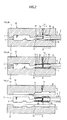
- Figures 1(a) through 1(f) are process drawings showing a manufacturing method for a wire harness 1 in which an insulator 4 coated on an end portion of an electric wire 2 is subj ected to diameter reduction and is cut off using a connecting device which will be described later.
- Figures 2(a) and (b) are process drawings showing a coating method for coating a connecting portion 6 with an insulating coating resin 7.
- the connecting device for manufacturing the wire harness 1 of the present embodiment is formed of an insulator cutting off unit A for cutting off the insulator 4 coated on an end portion of the electric wire 2, an insulator diameter reduction unit B for reducing a diameter of the insulator 4 coated on the end portion, a terminal crimping unit C for crimping the terminal 5 to the conductor 3 exposed at the end portion, and a resin coating unit D for coating the connecting portion 6 where the conductor 3 and the terminal 5 are connected with the coating resin 7.
- the insulator cutting off unit A is formed of a cutting blade Aa for cutting off the insulator 4 coated on the end portion of the electric wire 2. Specifically, without cutting the conductor 3 of the electric wire 2, the cutting blade Aa cuts off only the insulator 4 coated on the conductor 3 and exposes the conductor 3 for a desired length (see Figures 1(b) , 3(c), and 4(b)) .
- the insulator diameter reduction unit B is formed of pressurizing members Ba for applying a pressure diametrically toward the center of the electric wire 2 to an insulator 4a coated on the end portion of the electric wire 2.
- the pressurizing members Ba are provided in a circumferential direction in equal intervals with the axial center of the electric wire 2 being the center.
- a pressure is applied diametrically toward the axial center of electric wire 2 by the pressurizing members Ba to the insulator 4a coated on the end portion of the electric wire 2, and the diameter of the insulator 4a of that portion is reduced.
- the insulator 4a coated on the end portion of the electric wire 2 is subjected to a diameter reduction process such that an outer diameter of the coated resin 7 coated on the insulator 4a becomes smaller than a terminal insertion hole 9 of a connector housing 8 (see Figures 1(c) and 3(b)) .
- the terminal crimping unit C is formed of an existing terminal crimping device (not shown) which crimps the terminal 5 of a conductive metal to the conductor 3 exposed at the end portion of the electric wire 2.
- the above-mentioned terminal crimping device is formed of an anvil Ca (not shown) which supports a lower side of the terminal 5, and a crimper Cb (not shown) which calks and crimps the conductor crimping portion 5X of the terminal 5 to the conductor 3 of the electric wire 2.
- the conductor 3 exposed at the end portion of the electric wire 2 is inserted into the conductor crimping portion 5X of the terminal 5, and the lower side of the terminal 5 is supported by the anvil Ca. Then, a crimping piece 5a formed on the terminal 5 substantially into a U shape is calked by the crimper Cb and crimped to the conductor 3 of the electric wire 2, and the conductor crimping portion 5X of the terminal 5 is connected to the conductor 3 of the electric wire 2 (see Figures 1(d) , 3(d), and 4(c)) .
- the resin coating unit D is formed of a resin coating device 10 which coats the entire connecting portion 6 where the conductor 3 of the electric wire 2 and the terminal 5 are connected, and a resin coating device 20 which will be described later.
- the above-mentioned resin coating device 10 is formed of a pair of molds 11, 11, on which the connecting portion 6 where the conductor 3 of the electric wire 2 and the terminal 5 are connected is set. Inside the molds 11, shaping portions 12 of concave shapes which hold the connecting portion 6 where the conductor 3 and the terminal 5 are connected.
- a resin injection path 14 is formed to communicate with a resin injection space 13 which is formed between the above-mentioned connecting portion 6 and the shaping portions 12, 12.
- the resin injection path 14 is connected to a resin supply which supplies a thermoplastic molten resin (not shown).
- the coating resin 7 is coated so as to cover the entire connecting portion 6 formed of a conductor exposed portion 3X of a conductor 3, which is exposed at an end portion of the electric wire 2, an insulator coated portion 4X, which is a portion adjacent to the conductor exposed portion 3X and is coated with the insulator 4a, and a conductor crimping portion 5X of a terminal 5 , to which the conductor 3 of the electric wire 2 is connected, substantially equally.
- an insulator 4b on a tip side which is a portion to be inserted further from the inlet of the terminal insertion hole 9, is cut off from the insulator 4 coated on the end portion of the electric wire 2 by the cutting blade Aa of the insulator cutting off unit A, leaving the insulator 4a of the insulator coating portion 4X to be inserted around the inlet of the terminal insertion hole 9 of the connector housing 8.
- the conductor 3 of the electric wire 2 is exposed for a length which allows connection to the conductor crimping portion 5X of the terminal 5 (see Figures 1(a) and 1(b)) .
- a pressure is applied to the portion adjacent to the conductor exposed portion 3X of the conductor 3, i.e., the insulator 4a of the insulator coating portion 4X to be inserted into the terminal insertion hole 9 of the connector housing 8, in a diameter direction toward the axial center of the electric wire 2 by the pressurizing members Ba of the insulator diameter reduction unit B such that it becomes thin.
- the insulator 4a of the insulator coating portion 4X is treated with a diameter reduction process such that the outer diameter of the coated resin 7 coated on the insulator 4a is smaller than the terminal insertion hole 9 of the connector housing 8 (see Figure 1(c)) .
- the conductor 3 exposed at the end portion of the electric wire 2 is inserted into the conductor crimping portion 5X of the terminal 5 , and the lower side of the terminal 5 is supported by the anvil Ca of the terminal crimping unit C.
- the crimping piece 5a of the terminal 5 is treated with a calking process by the crimper Cb and is crimped to the conductor 3 of the electric wire 2 to connect the conductor crimping portion 5X of the terminal 5 to the conductor 3 of the electric wire 2 (see Figure 1(d) ) .
- the connecting portion 6 where the conductor 3 of the electric wire 2 and the terminal 5 are connected is set between molds 11 of the resin coating device 10, i.e., between shaping portions 12 of the molds 11. Then, molten resin supplied from the resin supply which is not shown is injected into the resin injection space 13 between the shaping portions 12 (see Figure 2(a)) .
- the coating resin 7 is applied to the connecting portion 6 formed of the conductor exposed portion 3X of the conductor 3 exposed at the end portion of the electric wire 2, the insulator coated portion 4X which is the portion adjacent to the conductor exposed portion 3X and is coated with the insulator 4, and the conductor crimping portion 5X of the terminal 5 , to which the conductor 3 of the electric wire 2 is connected, to cover the entire connecting portion 6 with the coating resin 7 in a substantially equal thickness (see Figure
- the molds 11 are separated vertically.
- the wire harness 1 which has been treated with a resin molding process is removed from the shaping portions 12 of the molds 11 (see Figure 2(c)) to complete manufacturing of the wire harness 1 (see Figure 1(e) ).
- the portion of the insulator 4a, which is to be inserted into the terminal insertion hole 9 of the connector housing 8, is treated with the diameter reduction process.
- the outer periphery of the coating resin 7 coated on the insulator 4a of the reduced diameter portion can be made smaller than the terminal insertion hole 9 of the connector housing 8.
- the outer peripheral surface of the coating resin 7 coated on the connecting portion 6 does not abut the inlet side peripheral portion of the terminal insertion hole 9.
- the terminal 5 connected to the electric wire 2 can be smoothly inserted into the terminal insertion hole 9 of the connector housing 8 (see Figure 1(f)) .
- the terminal 5 can be inserted into connector housings 8 with a smaller terminal insertion hole 9.
- it can be inserted into existing connector housings with small terminal insertion holes which have been applied to terminals which do not require coating with coating resins. Since the terminal insertion hole 9 of the connector housing 8 does not have to be processed to be a big hole, the connector housing 8 itself does not have to be enlarged, or a dedicated connector housing 8 does not have to be newly manufactured, the manufacturing cost can be reduced.
- the coating resin 7 to be coated on the insulator 4 can be made thick by that thickness. Therefore, environment deterioration such as crack, chap, or the like is unlikely to occur, and the waterproof property can be enhanced.
- the entire length of the connecting portion 6 from the insulator coating portion 4X to the conductor crimping portion 5X is coated with the coating resin 7, it becomes possible to ensure connection between the electric wire 2 and the terminal 5 with no external force being directly applied to the conductor crimping portion 5X even there is no insulation barrel for crimping the insulator formed on the terminal, for example.
- the outer periphery of the coated resin 7 coated on the connecting portion 6 of the wire harness 1 is formed so as to be substantially same as the inner periphery of the terminal insertion hole 9 of the connector housing 8, opposing surfaces of the coated resin 7 and the terminal insertion hole 9 contact each other closely. Accordingly, the terminal 5 of the wire harness 1 can be inserted into the terminal insertion hole 9 of the connector housing 8 without being loose.
- the conductor 3 of the electric wire 2 and the terminal 5 formed of dissimilar metals for example, an aluminum conductor and a copper terminal, or the like
- the entire connecting portion 6 formed of the conductor exposed portion 3X , the insulator coated portion 4X and the conductor crimping portion 5X is coated with the coating resin 7, air, water, and the like can be prevented from entering the connecting portion 6 of the conductor 3 and the terminal 5 , and the anticorrosion property can be enhanced.
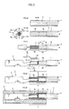
- Figures 3(a) through (f) are process drawings showing another manufacturing method for the wire harness 1 in which the insulator 4 coated on the end portion of the electric wire 2 is subjected to the diameter reduction and is cut off using the above-described connecting device.
- portions of the insulator 4 coated on the end portion of the electric wire 2, which are to be inserted into the terminal insertion hole 9 of the connector housing 8, i.e., the insulators 4a and 4b to be inserted into the terminal insertion hole 9 are pressurized in the radial direction toward the axial center of the electric wire 2 by the pressurizing members Ba of the insulator diameter reduction unit B and is processed so as to be thin.
- the insulators 4a and 4b are treated with the diameter reduction process such that the outer periphery of the coated resin 7 coated on the insulator 4a is smaller than the terminal insertion hole 9 of the connector housing 8 (see Figures 3(a) and 3(b)) .
- the insulator 4b of the tip side which is to be inserted further from the inlet of the terminal insertion hole 9, is cut off from the insulators 4a and 4b of the reduced diameter portions by the cutting blade Aa of the insulator cutting off unit A, leaving the insulator 4a of the insulator coated portion 4X to be inserted around the inlet of the terminal insertion hole 9 of the connector housing 8.
- the conductor 3 of the electric wire 2 is exposed for a length which allows connection to the conductor crimping portion 5X of the terminal 5 (see Figure 3(c)).
- the conductor 3 exposed at the end portion of the electric wire 2 is inserted into the conductor crimping portion 5X of the terminal 5 , and the lower side of the terminal 5 is supported by the anvil Ca of the terminal crimping unit C .
- the crimping piece 5a of the terminal 5 is treated with the calking process by the crimper Cb and is crimped to the conductor 3 of the electric wire 2 to connect the conductor crimping portion 5X of the terminal 5 to the conductor 3 of the electric wire 2 (see Figure 3(d)).
- the connecting portion 6 where the conductor 3 of the electric wire 2 and the terminal 5 are connected is set between the shaping portions 12 of the molds 11 of the resin coating device 10. Then, molten resin supplied from the resin supply which is not shown is injected into the resin injection space 13 between the shaping portions 12 (see Figure 2(a) ).
- the coating resin 7 is applied to the connecting portion 6 formed of the conductor exposed portion 3X of the conductor 3, which is exposed at the end portion of the electric wire 2, the insulator coated portion 4X which is the portion adjacent to the conductor exposed portion 3X and is coated with the insulator 4a, and the conductor crimping portion 5X of the terminal 5 , to which the conductor 3 of the electric wire 2 is connected, such that the coating resin 7 cover the entire connecting portion 6 in a substantially equal thickness (see Figure 2(d) ).
- the molds 11 are separated vertically.
- the wire harness 1 which has been treated with the resin molding process is removed from the shaping portions 12 of the molds 11 to complete manufacturing of the wire harness 1 (see Figure 3(e)).
- the wire harness 1 manufactured with the above-described connecting device and manufacturing method is treated with the diameter reduction process for the portion of the insulator 4a, which is to be inserted into the terminal insertion hole 9 of the connector housing 8.
- the outer periphery of the coating resin 7 coated on the insulator 4a of the reduced diameter portion can be made smaller than the terminal insertion hole 9 of the connector housing 8.
- the coating resin 7 coated on the connecting portion 6 does not abut the inlet side peripheral portion of the terminal insertion hole 9.
- the terminal 5 of the wire harness 1 can be smoothly inserted into the terminal insertion hole 9 of the connector housing 8 (see Figure 3(f)).
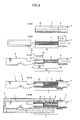
- Figures 4 (a ) through (e) are process drawings showing another manufacturing method for the wire harness 1 in which the insulator 4 coated on the end portion of the electric wire 2 is cut off by a length which allows the conductor 3 on the end side to be exposed on the outer side from the terminal insertion hole 9 of the connector housing 8 using the above-described connecting device.
- Figures 5 (a) and (b) are process drawings showing a coating method for coating the connecting portion 6 with the coating resin 7.
- the insulator 4b which is a portion from an insertion portion to be inserted into the terminal insertion hole 9 to an exposed portion to be exposed outside the terminal insertion hole 9 is cut off from the insulator 4 coated on the end portion of the electric wire 2 by the cutting blade Aa, leaving the insulator coating portion 4X to be protruded outward from the inlet of the terminal insertion hole 9 of the connector housing 8.
- the conductor 3 of the electric wire 2 is exposed by a length which allows it to be protruded outward from the inlet of the terminal insertion hole 9 (see Figures 4(a) and (b)) .
- the conductor 3 exposed at the end portion of the electric wire 2 is inserted into the conductor crimping portion 5X of the terminal 5 , and the lower side of the terminal 5 is supported by the anvil Ca of the terminal crimping unit C.
- the crimping piece 5a of the terminal 5 is treated with the calking process by the crimper Cb and is crimped to the conductor 3 of the electric wire 2 to connect the conductor crimping portion 5X of the terminal 5 to the conductor 3 of the electric wire 2 (see Figure 4(c)).
- the connecting portion 6 where the conductor 3 and the terminal 5 are connected is set between molds 21 of the resin coating device 20, i.e., between shaping portions 22 of the molds 21. Then, molten resin supplied from the resin supply which is not shown is injected into the resin injection space 23 between the shaping portions 22 via a resin injection path 24 (see Figure 5(a) ).
- the coating resin 7 is applied to the connecting portion 6 formed of a conductor exposed portion 3X of the conductor 3 exposed at an end portion of the electric wire 2, the insulator coated portion 4X which is the portion adjacent to the conductor exposed portion 3X and is coated with the insulator 4, and the conductor crimping portion 5X of the terminal 5 , to which the conductor 3 of the electric wire 2 is connected, such that the entire connecting portion 6 is covered with the coating resin 7 in a substantially equal thickness (see Figure 5(b) ).
- the coating resin 7 is directly applied to the conductor 3 to be inserted into the terminal insertion hole 9 of the connector housing 8, from which the insulator 4b has been stripped off.
- the molds 21 are separated vertically.
- the wire harness 1 which has been treated with the resin molding process is removed from the shaping portions 22 of the molds 21 (see Figure 5(c)) to complete manufacturing of the wire harness 1 (see Figure 4(d) ).
- the insulator 4b from the portion to be inserted into the terminal insertion hole 9 to the portion exposed outside the terminal insertion hole 9 is cut off leaving the insulator coating portion 4X of the insulator 4, which is protruded to the outer side from the terminal insertion hole 9 of the connector housing 8. Then, the coating resin 7 is directly coated on the conductor 3 from which the insulator 4b has been stripped off.
- the outer periphery of the coating resin 7 coated on the connecting portion 6 of the electric wire 2 can be made smaller than the terminal insertion hole 9 of the connector housing 8.
- an outer peripheral surface of the coating resin 7 coated on the connecting portion 6 does not abut the inlet side peripheral portion of the terminal insertion hole 9.
- the terminal 5 of the wire harness 1 can be smoothly inserted into the terminal insertion hole 9 of the connector housing 8 (see Figure 4(e)).
- the wire harness 1 When the wire harness 1 is manufactured with the above-described manufacturing method, only the conductor exposed portion 3X is the portion of the electric wire 2 in the terminal insertion hole 9. This can achieve better functions and effects than the above embodiments since there is no insulator 4 which is treated with the diameter reduction process. Also, since the step and a time period for the diameter reduction process for the insulator 4 coated on the end portion of the electric wire 2 can be omitted, the manufacturing cost can be reduced.
- the entire length of the connecting portion 6 from the insulator coating portion 4X to the conductor crimping portion 5X is coated with the coating resin 7, it becomes possible to ensure connection between the electric wire 2 and the terminal 5 with no external force being directly applied to the conductor crimping portion 5X even there is no insulation barrel for crimping the insulator formed on the terminal, for example.
- the resin coating device 20 has a substantially same structure as the resin coating device 10 in the above embodiments. Therefore, the detailed descriptions are omitted.
- the conductor 3 of the electric wire 2 and the terminal 5 are connected, and then, the insulator 4 coated on the end portion of the electric wire 2 may be treated with the diameter reduction process.
- the terminal 5 in the above embodiments is formed of a terminal in which only the crimping piece 5a (wire barrel) is formed. Alternatively, it may be formed of a terminal in which an insulation barrel and a wire barrel are formed.
Landscapes
- Engineering & Computer Science (AREA)
- Manufacturing & Machinery (AREA)
- Architecture (AREA)
- Civil Engineering (AREA)
- Structural Engineering (AREA)
- Connections Effected By Soldering, Adhesion, Or Permanent Deformation (AREA)
- Connector Housings Or Holding Contact Members (AREA)
Abstract
Description
- The present invention relates to a connecting structure, a connecting device and a connecting method for electric wires and terminals, and a wire harness which prevent corrosion in connecting portions of electric wire conductors and terminals.
- As a method for preventing corrosion (hereinafter, referred to as "anti-corrosion") in connecting portions between electric wire conductors and terminals to which the conductors are connected as mentioned above, a waterproof method and water proof device for end connecting portions of coated electric wires (see Patent Document 1) has been proposed, for example.
- More specifically, in the method and the device of
Patent Document 1, an end connecting portion where a conductor of a coated electric wire and a terminal metal fitting are connected is set in a cavity of a shaping die, and a side opening of the cavity from which the coated electric wire is drawn outside is blocked with an elastic baffle plate. Then, a molten mold resin is injected into the cavity to coat the end connecting portion with the mold resin. - However, as the above-mentioned mold resin also covers an insulating coating of the coated electric wire, an outer diameter of the mold resin coated on the insulating coating becomes large (see
Figure 3 of Patent Document 1). Accordingly, for example, as shown inFigure 6 , when a connecting portion of a coatedelectric wire 52 of awire harness 51 and aterminal metal fitting 55 is coated with amold resin 57 using the above-described method and the device, an outer diameter of themold resin 57 coated on theinsulating coating 54, which is to be inserted into aterminal insertion hole 59 of aconnector housing 58, becomes larger than an inner diameter of theterminal insertion hole 59. - Therefore, for inserting the
terminal metal fitting 55 connected to the coatedelectric wire 52 of thewire harness 51 into theterminal insertion hole 59 of theconnector housing 58, themold resin 57 coated on theinsulating coating 54 of the coatedelectric wire 52 abuts a peripheral portion of an inlet side of theterminal insertion hole 59, and theterminal metal fitting 55 cannot be inserted into a predetermined position. - Further, there is a problem that the
terminal insertion hole 59 of theconnector housing 58 has to be processed into a size which allows to insert the terminal metal fitting 55 coated with themold resin 57, theconnector housing 58 itself has to be enlarged, and/or adedicated connector housing 58 has to be manufactured, thereby increasing the cost. - Patent Document 1: Laid-open Patent Publication No.
2010-135121 - An objective of the present invention is to provide a connecting structure, a connecting device, and a connecting method for electric wires and terminals which allow terminals connected to electric wire conductors to be smoothly inserted into terminal insertion holes of connector housings, and a wire harness using electric wires having such a connecting structure.
- The present invention is characterized in that it is a connecting structure for an electric wire and a terminal, in which a terminal to be inserted into a terminal insertion hole of a connector housing is crimped to a conductor exposed by stripping off a coated insulator at an end portion of an electric wire, and a coating resin coated on a connecting portion formed of a conductor exposed portion of the conductor exposed at the end portion of the electric wire, an insulator coated portion which is adjacent to the conductor exposed portion and is coated with the insulator, and a conductor crimping portion of the terminal, to which the conductor is connected, is formed into a thickness which allows it to be inserted into the terminal insertion hole of the connector housing.
- With the above connecting structure, the coated resin coated on the connecting portion of the conductor of the electric wire and the terminal is formed into a thickness which allows it to be inserted into the terminal insertion hole of the connector housing. Thus, the terminal connected to the electric wire can be smoothly inserted into the terminal insertion hole of the connector housing.
- As a result, the terminal can be inserted into a connector housing with a smaller terminal insertion hole. For example, it can be inserted into existing connector housings with small terminal insertion holes which have been applied to terminals which do not require coating with coating resins.
Therefore, the terminal insertion hole of the connector housing does not have to be processed to be a big hole, the connector housing itself does not have to be enlarged, or a dedicated connector housing does not have to be newly manufactured. - Further, since the connecting portion from the insulator coating portion to the conductor crimping portion is coated with the coating resin, it becomes possible to ensure connection between the terminal and the electric wire with no external force being directly applied to the conductor crimping portion even there is no insulation barrel for crimping the insulator formed on the terminal, for example.
- In one embodiment of the present invention, a portion of the insulator coated on the end portion of the electric wire, which is to be inserted further from an inlet of the terminal insertion hole, may be stripped off, and the insulator of the insulator coated portion, which is to be inserted around the inlet of the terminal insertion hole, may be processed to be thin.
- Further, a portion of the insulator coated on the end portion of the electric wire, which is to be inserted into the terminal insertion hole, may be processed to be thin, and a portion of the insulator, which is to be inserted further from an inlet of the terminal insertion hole, may be stripped off, leaving the insulator coated portion which is to be inserted around the inlet of the terminal insertion hole.
- With the above connecting structure, as the insulator of the insulator coated portion to be inserted into the terminal insertion hole is made thin, the coated resin coated on the insulator can be formed into a thickness which allows it to be inserted into the terminal insertion hole of the connector housing.
- As a result, even when the coating resin covers the insulator of the electric wire to be inserted into the terminal insertion hole of the connector housing, the terminal to which the electric wire is connected can be smoothly inserted into the terminal insertion hole of the connector housing.
- Accordingly, in the case where the terminal cannot be smoothly inserted into the terminal insertion hole, a poor electrical connection, which may happen when the connector is connected because the terminal cannot be inserted to a predetermined position of the terminal insertion hole, can be prevented.
- Further, as the insulator is made thin, the coating resin to be coated on the insulator can be made thick by that thickness. Therefore, environment deterioration such as crack, chap, or the like is unlikely to occur, and the waterproof property can be enhanced.
- In one embodiment of the present invention, the insulator coated on the end portion of the electric wire may be stripped off such that the conductor is exposed for a long length to an outer side from an inlet of the terminal insertion hole.
- With the above connecting structure, the coating resin is directly coated on the conductor exposed for a long length to the outer side from the inlet of the terminal insertion hole. Thus, the thickness of the coating resin can be reduced from that for coating the coating resin on the insulator by the thickness of the insulator, thereby reducing the size.
- As a result, the coating resin almost never contacts an inner wall of the terminal insertion hole, or even when it does, contact resistance is so small that the terminal can be smoothly inserted.
- The present invention is characterized in that it is a wire harness formed of an electric wire having a connecting structure as described above.
- With the above wire harness, the terminal connected to the electric wire can be smoothly inserted into the terminal insertion hole of the connector housing, and also, corrosion in the connecting portion of the conductor and the terminal formed of dissimilar metals, for example, an aluminum conductor and a copper terminal or the like, can be prevented.
- As a result, a manufacturing efficiency for the wire harness can be improved, and also, a stable connection state can be maintained for a long time.
- Further, the present invention is characterized in that it is a connecting device for connecting an electric wire and a terminal, in which a terminal to be inserted into a terminal insertion hole of a connector housing is crimped to a conductor exposed by stripping off a coated insulator at an end portion of an electric wire, comprising: insulator stripping means for stripping off the insulator coated on the end portion of the electric wire; terminal crimping means for crimping the terminal to the conductor exposed by stripping off the insulator; and resin coating means for coating a coating resin on a connecting portion formed of a conductor exposed portion of the conductor exposed at the end portion of the electric wire, an insulator coated portion which is adjacent to the conductor exposed portion and is coated with the insulator, and a conductor crimping portion of the terminal to which the conductor is connected, into a thickness which allows it to be inserted into the terminal insertion hole of the connector housing.
- With the above connecting device, the coated resin is coated by the resin coating means on the connecting portion of the conductor of the electric wire and the terminal into a thickness which allows it to be inserted into the terminal insertion hole of the connector housing. Thus, the terminal connected to the electric wire can be smoothly inserted into the terminal insertion hole of the connector housing.
- As a result, the terminal can be inserted into a connector housing with a smaller terminal insertion hole, and for example, a wire harness using existing connector housings with small terminal insertion holes, which have been applied to terminals which do not require coating with coating resins, can be manufactured without necessity of processing the terminal insertion hole of the connector housing to be a big hole, enlarging the connector housing itself, or newly manufacturing a dedicated connector housing.
- In one embodiment of the present invention, a portion of the insulator coated on the end portion of the electric wire, which is to be inserted further from an inlet of the terminal insertion hole, may be stripped off by the insulator stripping means, and the insulator of the insulator coated portion, which is to be inserted around the inlet of the terminal insertion hole, may be processed to be thin by insulator thinning means.
- Further, a portion of the insulator coated on the end portion of the electric wire, which is to be inserted into the terminal insertion hole, may be processed to be thin by the insulator thinning means, and a portion of the insulator, which is to be inserted further from an inlet of the terminal insertion hole, may be stripped off by the insulator stripping means, leaving the insulator coated portion which is to be inserted around the inlet of the terminal insertion hole.
- With the above connecting device, as the insulator of the insulator coated portion to be inserted into the terminal insertion hole is made thin, the coated resin coated on the insulator can be formed into a thickness which allows it to be inserted into the terminal insertion hole of the connector housing.
- As a result, even when the coating resin covers the insulator of the electric wire to be inserted into the terminal insertion hole of the connector housing, the terminal to which the electric wire is connected can be smoothly inserted into the terminal insertion hole of the connector housing.
- Accordingly, in the case where the terminal cannot be smoothly inserted into the terminal insertion hole, a poor electrical connection, which may happen when the connector is connected because the terminal cannot be inserted to a predetermined position of the terminal insertion hole, can be prevented.
- Further, as the insulator is made thin, the coating resin to be coated on the insulator can be made thick by that thickness. Therefore, environment deterioration such as crack, chap, or the like is unlikely to occur, and the waterproof property can be enhanced.
- In one embodiment of the present invention, the insulator coated on the end portion of the electric wire may be stripped off by the insulator stripping means such that the conductor is exposed for a long length to an outer side from an inlet of the terminal insertion hole.
- With the above connecting device, the coating resin is directly coated on the conductor exposed for a long length to the outer side from the inlet of the terminal insertion hole. Thus, the thickness of the coating resin can be reduced from that for coating the coating resin on the insulator by the thickness of the insulator, thereby reducing the size.
- As a result, the coating resin almost never contacts an inner wall of the terminal insertion hole, or even when it does, contact resistance is so small that the terminal can be smoothly inserted.
- Further, the present invention is characterized in that it is a connecting method for an electric wire and a terminal, in which a terminal to be inserted into a terminal insertion hole of a connector housing is crimped to a conductor exposed by stripping off a coated insulator at an end portion of an electric wire, wherein: the insulator coated on the end portion of the electric wire is stripped off, and the terminal is crimped to the conductor exposed by stripping off the insulator; and a connecting portion formed of a conductor exposed portion of the conductor exposed at the end portion of the electric wire, an insulator coated portion which is adjacent to the conductor exposed portion and is coated with the insulator, and a conductor crimping portion of the terminal to which the conductor is connected, is coated with a coating resin into a thickness which allows it to be inserted into the terminal insertion hole of the connector housing.
- With the above connecting method, the coated resin is coated on the connecting portion of the conductor of the electric wire and the terminal into a thickness which allows it to be inserted into the terminal insertion hole of the connector housing. Thus, the terminal connected to the electric wire can be smoothly inserted into the terminal insertion hole of the connector housing.
- As a result, it can be inserted into terminal insertion holes of existing connector housings the terminal without necessity of processing the terminal insertion hole of the connector housing to be a big hole, enlarging the connector housing itself, or newly manufacturing a dedicated connector housing.
- Further, since the connecting portion from the insulator coating portion to the conductor crimping portion is coated with the coating resin, it becomes possible to ensure connection between the terminal and the electric wire with no external force being directly applied to the conductor crimping portion even there is no insulation barrel for crimping the insulator formed on the terminal, for example.
- In one embodiment of the present invention, a portion of the insulator coated on the end portion of the electric wire, which is to be inserted further from an inlet of the terminal insertion hole, may be stripped off, and the insulator of the insulator coated portion, which is to be inserted around the inlet of the terminal insertion hole, may be processed to be thin.
- Further, a portion of the insulator coated on the end portion of the electric wire, which is to be inserted into the terminal insertion hole, may be processed to be thin, and a portion of the insulator, which is to be inserted further from an inlet of the terminal insertion hole, may be stripped off, leaving the insulator coated portion which is to be inserted around the inlet of the terminal insertion hole.
- With the above connecting method, as the portion of the insulator to be inserted into the terminal insertion hole is made thin, the coated resin coated on the insulator can be formed into a thickness which allows it to be inserted into the terminal insertion hole of the connector housing.
- As a result, even when the coating resin covers the insulator of the electric wire to be inserted into the terminal insertion hole of the connector housing, the terminal to which the electric wire is connected can be smoothly inserted into the terminal insertion hole of the connector housing.
- Accordingly, in the case where the terminal cannot be smoothly inserted into the terminal insertion hole, a poor electrical connection, which may happen when the connector is connected because the terminal cannot be inserted to a predetermined position of the terminal insertion hole, can be prevented.
- Further, as the insulator is made thin, the coating resin to be coated on the insulator can be made thick by that thickness. Therefore, environment deterioration such as crack, chap, or the like is unlikely to occur, and the waterproof property can be enhanced.
- In one embodiment of the present invention, the insulator coated on the end portion of the electric wire may be stripped off such that the conductor is exposed for a long length to an outer side from an inlet of the terminal insertion hole.
- With the above connecting method, the coating resin is directly coated on the conductor exposed for a long length to the outer side from the inlet of the terminal insertion hole. Thus, the thickness of the coating resin can be reduced from that for coating the coating resin on the insulator by the thickness of the insulator, thereby reducing the size.
- As a result, the coating resin almost never contacts an inner wall of the terminal insertion hole, or even when it does, contact resistance is so small that the terminal can be smoothly inserted.
- The conductor of the electric wire may be formed of, for example, aluminum, aluminum alloy, copper or the like. Further, the terminal may be formed of, for example, copper, copper alloy or the like.
- Further, the insulator thinning means may be formed of diameter reduction means for reducing diameter by applying a pressure to the insulator in a radial direction, cutting off means for cutting off by a cutting blade, laser or the like, cutting means for cutting by a cutting tool or cutting by blowing a fluid, heating means for diameter reduction by applying heat, dissolving means for dissolving by chemicals, solvent, or the like, and so on.
- According to the present invention, the coated resin coated on the connecting portion of the conductor of the electric wire and the terminal is formed into a thickness which allows it to be inserted into the terminal insertion hole of the connector housing. Thus, the terminal connected to the conductor of the electric wire can be smoothly inserted into the terminal insertion hole of the connector housing.
-
- [
Figure 1 ] Process drawings showing a manufacturing method in which an insulator on an electric wire end portion is subjected to diameter reduction and is cut off. - [
Figure 2 ] Process drawings showing a coating method for coating a connecting portion with a coating resin. - [
Figure 3 ] Process drawings showing another manufacturing method in which the insulator on the electric wire end portion is cut off and is subjected to diameter reduction. - [
Figure 4 ] Process drawings showing another manufacturing method in which the insulator on the electric wire end portion is cut off. - [
Figure 5 ] Process drawings showing a coating method for coating with the coating resin. - [
Figure 6 ] Cross-sectional side views showing an inserted state in a conventional wire harness. - Hereinafter, an embodiment of the present invention will be described in details with reference of the drawings.
Figures 1(a) through 1(f) are process drawings showing a manufacturing method for awire harness 1 in which aninsulator 4 coated on an end portion of anelectric wire 2 is subj ected to diameter reduction and is cut off using a connecting device which will be described later.Figures 2(a) and (b) are process drawings showing a coating method for coating a connectingportion 6 with an insulatingcoating resin 7. - In the
wire harness 1 of the present embodiment, an entire connectingportion 6 formed of a conductor exposedportion 3X of aconductor 3, which is exposed at an end portion of theelectric wire 2, an insulator coatedportion 4X, which is a portion adjacent to the conductor exposedportion 3X and is coated with theinsulator 4, and aconductor crimping portion 5X of aterminal 5, which is crimped to theconductor 3 of theelectric wire 2, is coated with thecoating resin 7. - The connecting device for manufacturing the
wire harness 1 of the present embodiment is formed of an insulator cutting off unit A for cutting off theinsulator 4 coated on an end portion of theelectric wire 2, an insulator diameter reduction unit B for reducing a diameter of theinsulator 4 coated on the end portion, a terminal crimping unit C for crimping theterminal 5 to theconductor 3 exposed at the end portion, and a resin coating unit D for coating the connectingportion 6 where theconductor 3 and theterminal 5 are connected with thecoating resin 7. - The insulator cutting off unit A is formed of a cutting blade Aa for cutting off the
insulator 4 coated on the end portion of theelectric wire 2. Specifically, without cutting theconductor 3 of theelectric wire 2, the cutting blade Aa cuts off only theinsulator 4 coated on theconductor 3 and exposes theconductor 3 for a desired length (seeFigures 1(b) , 3(c), and 4(b)) . - The insulator diameter reduction unit B is formed of pressurizing members Ba for applying a pressure diametrically toward the center of the
electric wire 2 to aninsulator 4a coated on the end portion of theelectric wire 2. The pressurizing members Ba are provided in a circumferential direction in equal intervals with the axial center of theelectric wire 2 being the center. - Specifically, a pressure is applied diametrically toward the axial center of
electric wire 2 by the pressurizing members Ba to theinsulator 4a coated on the end portion of theelectric wire 2, and the diameter of theinsulator 4a of that portion is reduced. In other words, theinsulator 4a coated on the end portion of theelectric wire 2 is subjected to a diameter reduction process such that an outer diameter of thecoated resin 7 coated on theinsulator 4a becomes smaller than aterminal insertion hole 9 of a connector housing 8 (seeFigures 1(c) and 3(b)) . - The terminal crimping unit C is formed of an existing terminal crimping device (not shown) which crimps the
terminal 5 of a conductive metal to theconductor 3 exposed at the end portion of theelectric wire 2.
The above-mentioned terminal crimping device is formed of an anvil Ca (not shown) which supports a lower side of theterminal 5, and a crimper Cb (not shown) which calks and crimps theconductor crimping portion 5X of theterminal 5 to theconductor 3 of theelectric wire 2. - Specifically, the
conductor 3 exposed at the end portion of theelectric wire 2 is inserted into theconductor crimping portion 5X of theterminal 5, and the lower side of theterminal 5 is supported by the anvil Ca. Then, a crimpingpiece 5a formed on theterminal 5 substantially into a U shape is calked by the crimper Cb and crimped to theconductor 3 of theelectric wire 2, and theconductor crimping portion 5X of theterminal 5 is connected to theconductor 3 of the electric wire 2 (seeFigures 1(d) ,3(d), and 4(c)). - The resin coating unit D is formed of a
resin coating device 10 which coats the entire connectingportion 6 where theconductor 3 of theelectric wire 2 and theterminal 5 are connected, and aresin coating device 20 which will be described later. - As shown in
Figure 2 , the above-mentionedresin coating device 10 is formed of a pair ofmolds portion 6 where theconductor 3 of theelectric wire 2 and theterminal 5 are connected is set. Inside themolds 11, shapingportions 12 of concave shapes which hold the connectingportion 6 where theconductor 3 and theterminal 5 are connected. - In one or both of the
molds 11, aresin injection path 14 is formed to communicate with aresin injection space 13 which is formed between the above-mentioned connectingportion 6 and the shapingportions resin injection path 14 is connected to a resin supply which supplies a thermoplastic molten resin (not shown). - Specifically, the
coating resin 7 is coated so as to cover the entire connectingportion 6 formed of a conductor exposedportion 3X of aconductor 3, which is exposed at an end portion of theelectric wire 2, an insulator coatedportion 4X, which is a portion adjacent to the conductor exposedportion 3X and is coated with theinsulator 4a, and aconductor crimping portion 5X of aterminal 5, to which theconductor 3 of theelectric wire 2 is connected, substantially equally. - A manufacturing method for manufacturing a
wire harness 1 with the above-described connecting device will be described.
First, aninsulator 4b on a tip side, which is a portion to be inserted further from the inlet of theterminal insertion hole 9, is cut off from theinsulator 4 coated on the end portion of theelectric wire 2 by the cutting blade Aa of the insulator cutting off unit A, leaving theinsulator 4a of theinsulator coating portion 4X to be inserted around the inlet of theterminal insertion hole 9 of theconnector housing 8.
In other words, theconductor 3 of theelectric wire 2 is exposed for a length which allows connection to theconductor crimping portion 5X of the terminal 5 (seeFigures 1(a) and 1(b)) . - Next, a pressure is applied to the portion adjacent to the conductor exposed
portion 3X of theconductor 3, i.e., theinsulator 4a of theinsulator coating portion 4X to be inserted into theterminal insertion hole 9 of theconnector housing 8, in a diameter direction toward the axial center of theelectric wire 2 by the pressurizing members Ba of the insulator diameter reduction unit B such that it becomes thin. - In this way, the
insulator 4a of theinsulator coating portion 4X is treated with a diameter reduction process such that the outer diameter of thecoated resin 7 coated on theinsulator 4a is smaller than theterminal insertion hole 9 of the connector housing 8 (seeFigure 1(c)) . - Next, for connecting the
terminal 5 to theconductor 3 of theelectric wire 2, theconductor 3 exposed at the end portion of theelectric wire 2 is inserted into theconductor crimping portion 5X of theterminal 5, and the lower side of theterminal 5 is supported by the anvil Ca of the terminal crimping unit C. Then, the crimpingpiece 5a of theterminal 5 is treated with a calking process by the crimper Cb and is crimped to theconductor 3 of theelectric wire 2 to connect theconductor crimping portion 5X of theterminal 5 to theconductor 3 of the electric wire 2 (seeFigure 1(d)) . - Next, in the resin coating unit D shown in
Figure 2 , the connectingportion 6 where theconductor 3 of theelectric wire 2 and theterminal 5 are connected is set betweenmolds 11 of theresin coating device 10, i.e., between shapingportions 12 of themolds 11. Then, molten resin supplied from the resin supply which is not shown is injected into theresin injection space 13 between the shaping portions 12 (seeFigure 2(a)) . - The
coating resin 7 is applied to the connectingportion 6 formed of the conductor exposedportion 3X of theconductor 3 exposed at the end portion of theelectric wire 2, the insulator coatedportion 4X which is the portion adjacent to the conductor exposedportion 3X and is coated with theinsulator 4, and theconductor crimping portion 5X of theterminal 5, to which theconductor 3 of theelectric wire 2 is connected, to cover the entire connectingportion 6 with thecoating resin 7 in a substantially equal thickness (see Figure - Then, after the molding process which coats the connecting
portion 6 with thecoating resin 7 as described above is finished, themolds 11 are separated vertically. Thewire harness 1 which has been treated with a resin molding process is removed from the shapingportions 12 of the molds 11 (seeFigure 2(c)) to complete manufacturing of the wire harness 1 (seeFigure 1(e) ). - In the
wire harness 1 manufactured with the above-described connecting device and manufacturing method, the portion of theinsulator 4a, which is to be inserted into theterminal insertion hole 9 of theconnector housing 8, is treated with the diameter reduction process. Thus, the outer periphery of thecoating resin 7 coated on theinsulator 4a of the reduced diameter portion can be made smaller than theterminal insertion hole 9 of theconnector housing 8. - Therefore, for inserting the
terminal 5 connected to theelectric wire 2 of thewire harness 1 into theterminal insertion hole 9 of theconnector housing 8, the outer peripheral surface of thecoating resin 7 coated on the connectingportion 6 does not abut the inlet side peripheral portion of theterminal insertion hole 9. Theterminal 5 connected to theelectric wire 2 can be smoothly inserted into theterminal insertion hole 9 of the connector housing 8 (seeFigure 1(f)) . - Further, in the case where the
terminal 5 cannot be smoothly inserted into theterminal insertion hole 9, a poor electrical connection, which may happen when the connector is connected because theterminal 5 cannot be inserted to a predetermined position of theterminal insertion hole 9, can be prevented. - As a result, the
terminal 5 can be inserted intoconnector housings 8 with a smallerterminal insertion hole 9. For example, it can be inserted into existing connector housings with small terminal insertion holes which have been applied to terminals which do not require coating with coating resins. Since theterminal insertion hole 9 of theconnector housing 8 does not have to be processed to be a big hole, theconnector housing 8 itself does not have to be enlarged, or adedicated connector housing 8 does not have to be newly manufactured, the manufacturing cost can be reduced. - Further, as the
insulator 4 is made thin, thecoating resin 7 to be coated on theinsulator 4 can be made thick by that thickness. Therefore, environment deterioration such as crack, chap, or the like is unlikely to occur, and the waterproof property can be enhanced. - Further, since the entire length of the connecting
portion 6 from theinsulator coating portion 4X to theconductor crimping portion 5X is coated with thecoating resin 7, it becomes possible to ensure connection between theelectric wire 2 and theterminal 5 with no external force being directly applied to theconductor crimping portion 5X even there is no insulation barrel for crimping the insulator formed on the terminal, for example. - Further, when the outer periphery of the
coated resin 7 coated on the connectingportion 6 of thewire harness 1 is formed so as to be substantially same as the inner periphery of theterminal insertion hole 9 of theconnector housing 8, opposing surfaces of thecoated resin 7 and theterminal insertion hole 9 contact each other closely. Accordingly, theterminal 5 of thewire harness 1 can be inserted into theterminal insertion hole 9 of theconnector housing 8 without being loose. - Further, in the case where the
conductor 3 of theelectric wire 2 and theterminal 5 formed of dissimilar metals, for example, an aluminum conductor and a copper terminal, or the like, are connected, since the entire connectingportion 6 formed of the conductor exposedportion 3X, the insulator coatedportion 4X and theconductor crimping portion 5X is coated with thecoating resin 7, air, water, and the like can be prevented from entering the connectingportion 6 of theconductor 3 and theterminal 5, and the anticorrosion property can be enhanced. - As a result, even when a difference between normal electrode potentials of the
conductor 3 and theterminal 5 is large, corrosion due to entrance of water and potential difference, i.e., dissimilar metals corrosion does not occur and stable connected state can be maintained. -
Figures 3(a) through (f) are process drawings showing another manufacturing method for thewire harness 1 in which theinsulator 4 coated on the end portion of theelectric wire 2 is subjected to the diameter reduction and is cut off using the above-described connecting device.
In the above-mentioned manufacturing method, portions of theinsulator 4 coated on the end portion of theelectric wire 2, which are to be inserted into theterminal insertion hole 9 of theconnector housing 8, i.e., theinsulators terminal insertion hole 9 are pressurized in the radial direction toward the axial center of theelectric wire 2 by the pressurizing members Ba of the insulator diameter reduction unit B and is processed so as to be thin. - In this way, the
insulators coated resin 7 coated on theinsulator 4a is smaller than theterminal insertion hole 9 of the connector housing 8 (seeFigures 3(a) and 3(b)) . - Next, the
insulator 4b of the tip side, which is to be inserted further from the inlet of theterminal insertion hole 9, is cut off from theinsulators insulator 4a of the insulator coatedportion 4X to be inserted around the inlet of theterminal insertion hole 9 of theconnector housing 8.
Specifically, theconductor 3 of theelectric wire 2 is exposed for a length which allows connection to theconductor crimping portion 5X of the terminal 5 (seeFigure 3(c)). - Next, for connecting the
terminal 5 to theconductor 3 of theelectric wire 2, theconductor 3 exposed at the end portion of theelectric wire 2 is inserted into theconductor crimping portion 5X of theterminal 5, and the lower side of theterminal 5 is supported by the anvil Ca of the terminal crimping unit C. Then, the crimpingpiece 5a of theterminal 5 is treated with the calking process by the crimper Cb and is crimped to theconductor 3 of theelectric wire 2 to connect theconductor crimping portion 5X of theterminal 5 to theconductor 3 of the electric wire 2 (seeFigure 3(d)). - Next, in the resin coating unit D shown in
Figure 2 , for coating the connectingportion 6 where theconductor 3 of theelectric wire 2 and theterminal 5 are connected with thecoating resin 7, the connectingportion 6 where theconductor 3 and theterminal 5 are connected is set between the shapingportions 12 of themolds 11 of theresin coating device 10. Then, molten resin supplied from the resin supply which is not shown is injected into theresin injection space 13 between the shaping portions 12 (seeFigure 2(a) ). - The
coating resin 7 is applied to the connectingportion 6 formed of the conductor exposedportion 3X of theconductor 3, which is exposed at the end portion of theelectric wire 2, the insulator coatedportion 4X which is the portion adjacent to the conductor exposedportion 3X and is coated with theinsulator 4a, and theconductor crimping portion 5X of theterminal 5, to which theconductor 3 of theelectric wire 2 is connected, such that thecoating resin 7 cover the entire connectingportion 6 in a substantially equal thickness (seeFigure 2(d) ). - Then, after the molding process which coats the connecting
portion 6 with thecoating resin 7 as described above is finished, themolds 11 are separated vertically. Thewire harness 1 which has been treated with the resin molding process is removed from the shapingportions 12 of themolds 11 to complete manufacturing of the wire harness 1 (seeFigure 3(e)). - The
wire harness 1 manufactured with the above-described connecting device and manufacturing method is treated with the diameter reduction process for the portion of theinsulator 4a, which is to be inserted into theterminal insertion hole 9 of theconnector housing 8. Thus, the outer periphery of thecoating resin 7 coated on theinsulator 4a of the reduced diameter portion can be made smaller than theterminal insertion hole 9 of theconnector housing 8. - Therefore, for inserting the
terminal 5 of thewire harness 1 into theterminal insertion hole 9 of theconnector housing 8, thecoating resin 7 coated on the connectingportion 6 does not abut the inlet side peripheral portion of theterminal insertion hole 9. Theterminal 5 of thewire harness 1 can be smoothly inserted into theterminal insertion hole 9 of the connector housing 8 (seeFigure 3(f)). - Further, in the case where the
terminal 5 cannot be smoothly inserted into theterminal insertion hole 9, a poor electrical connection, which may happen when the connector is connected because theterminal 5 cannot be inserted to the predetermined position of theterminal insertion hole 9, can be prevented.
As a result, functions and effects substantially similar to those of the above-described embodiment can be achieved. -
Figures 4 (a) through (e) are process drawings showing another manufacturing method for thewire harness 1 in which theinsulator 4 coated on the end portion of theelectric wire 2 is cut off by a length which allows theconductor 3 on the end side to be exposed on the outer side from theterminal insertion hole 9 of theconnector housing 8 using the above-described connecting device.Figures 5(a) and (b) are process drawings showing a coating method for coating the connectingportion 6 with thecoating resin 7. - In the above-mentioned manufacturing method for manufacturing the
wire harness 1, theinsulator 4b which is a portion from an insertion portion to be inserted into theterminal insertion hole 9 to an exposed portion to be exposed outside theterminal insertion hole 9 is cut off from theinsulator 4 coated on the end portion of theelectric wire 2 by the cutting blade Aa, leaving theinsulator coating portion 4X to be protruded outward from the inlet of theterminal insertion hole 9 of theconnector housing 8.
In other words, theconductor 3 of theelectric wire 2 is exposed by a length which allows it to be protruded outward from the inlet of the terminal insertion hole 9 (seeFigures 4(a) and (b)). - Next, for connecting the
terminal 5 to theconductor 3 of theelectric wire 2, theconductor 3 exposed at the end portion of theelectric wire 2 is inserted into theconductor crimping portion 5X of theterminal 5, and the lower side of theterminal 5 is supported by the anvil Ca of the terminal crimping unit C. Then, the crimpingpiece 5a of theterminal 5 is treated with the calking process by the crimper Cb and is crimped to theconductor 3 of theelectric wire 2 to connect theconductor crimping portion 5X of theterminal 5 to theconductor 3 of the electric wire 2 (seeFigure 4(c)). - Next, in a resin coating unit D shown in
Figure 5 , as in the above-described embodiments, the connectingportion 6 where theconductor 3 and theterminal 5 are connected is set betweenmolds 21 of theresin coating device 20, i.e., between shapingportions 22 of themolds 21. Then, molten resin supplied from the resin supply which is not shown is injected into theresin injection space 23 between the shapingportions 22 via a resin injection path 24 (seeFigure 5(a)). - The
coating resin 7 is applied to the connectingportion 6 formed of a conductor exposedportion 3X of theconductor 3 exposed at an end portion of theelectric wire 2, the insulator coatedportion 4X which is the portion adjacent to the conductor exposedportion 3X and is coated with theinsulator 4, and theconductor crimping portion 5X of theterminal 5, to which theconductor 3 of theelectric wire 2 is connected, such that the entire connectingportion 6 is covered with thecoating resin 7 in a substantially equal thickness (seeFigure 5(b) ).
In other words, thecoating resin 7 is directly applied to theconductor 3 to be inserted into theterminal insertion hole 9 of theconnector housing 8, from which theinsulator 4b has been stripped off. - Then, after the molding process which coats the connecting
portion 6 with thecoating resin 7 as described above is finished, themolds 21 are separated vertically. Thewire harness 1 which has been treated with the resin molding process is removed from the shapingportions 22 of the molds 21 (seeFigure 5(c)) to complete manufacturing of the wire harness 1 (seeFigure 4(d) ). - In the
wire harness 1 manufactured with the above-described connecting device and manufacturing method, theinsulator 4b from the portion to be inserted into theterminal insertion hole 9 to the portion exposed outside theterminal insertion hole 9 is cut off leaving theinsulator coating portion 4X of theinsulator 4, which is protruded to the outer side from theterminal insertion hole 9 of theconnector housing 8. Then, thecoating resin 7 is directly coated on theconductor 3 from which theinsulator 4b has been stripped off. - In this way, the outer periphery of the
coating resin 7 coated on the connectingportion 6 of theelectric wire 2 can be made smaller than theterminal insertion hole 9 of theconnector housing 8. - Therefore, for inserting the
terminal 5 of thewire harness 1 into theterminal insertion hole 9 of theconnector housing 8, an outer peripheral surface of thecoating resin 7 coated on the connectingportion 6 does not abut the inlet side peripheral portion of theterminal insertion hole 9. Theterminal 5 of thewire harness 1 can be smoothly inserted into theterminal insertion hole 9 of the connector housing 8 (seeFigure 4(e)). - When the
wire harness 1 is manufactured with the above-described manufacturing method, only the conductor exposedportion 3X is the portion of theelectric wire 2 in theterminal insertion hole 9. This can achieve better functions and effects than the above embodiments since there is noinsulator 4 which is treated with the diameter reduction process. Also, since the step and a time period for the diameter reduction process for theinsulator 4 coated on the end portion of theelectric wire 2 can be omitted, the manufacturing cost can be reduced. - Further, since the entire length of the connecting
portion 6 from theinsulator coating portion 4X to theconductor crimping portion 5X is coated with thecoating resin 7, it becomes possible to ensure connection between theelectric wire 2 and theterminal 5 with no external force being directly applied to theconductor crimping portion 5X even there is no insulation barrel for crimping the insulator formed on the terminal, for example. - The
resin coating device 20 has a substantially same structure as theresin coating device 10 in the above embodiments. Therefore, the detailed descriptions are omitted. - In the correspondence between the structure of the present invention and the above-described embodiments:
- The insulator stripping means of the present invention corresponds to the insulator cutting off unit A;
- The insulator thinning means corresponds to the insulator diameter reduction unit B;
- The terminal crimping means corresponds to the terminal crimping unit C; and
- The resin coating means corresponds to the resin coating unit D.
- For example, the
conductor 3 of theelectric wire 2 and theterminal 5 are connected, and then, theinsulator 4 coated on the end portion of theelectric wire 2 may be treated with the diameter reduction process.
Further, theterminal 5 in the above embodiments is formed of a terminal in which only the crimpingpiece 5a (wire barrel) is formed. Alternatively, it may be formed of a terminal in which an insulation barrel and a wire barrel are formed. -
- A ... Insulator cutting off unit
- B ... Insulator diameter reduction unit
- C ... Terminal crimping unit
- D ... Resin coating unit
- 1 ... Wire harness
- 2 ... Electric wire
- 3 ... Conductor
- 3X ... Conductor exposed portion
- 4, 4a, 4b ... Insulator
- 5 ... Terminal
- 5a ... Crimping piece
- 5X ... Conductor crimping portion
- 6 ... Connecting portion
- 7 ... Coating resin
- 8 ... Connector housing
- 9 ... Terminal insertion hole
- 10, 20 ... Resin coating device
- 11, 21 ... Mold
Claims (13)
- A connecting structure for an electric wire and a terminal, in which a terminal to be inserted into a terminal insertion hole of a connector housing is crimped to a conductor exposed by stripping off a coated insulator at an end portion of an electric wire, and
a coating resin coated on a connecting portion formed of a conductor exposed portion of the conductor exposed at the end portion of the electric wire, an insulator coated portion which is adjacent to the conductor exposed portion and is coated with the insulator, and a conductor crimping portion of the terminal, to which the conductor is connected, is formed into a thickness which allows it to be inserted into the terminal insertion hole of the connector housing. - A connecting structure for an electric wire and a terminal according to claim 1, wherein:a portion of the insulator coated on the end portion of the electric wire, which is to be inserted further from an inlet of the terminal insertion hole, is stripped off, and the insulator of the insulator coated portion, which is to be inserted around the inlet of the terminal insertion hole, is processed to be thin.
- A connecting structure for an electric wire and a terminal according to claim 1, wherein:a portion of the insulator coated on the end portion of the electric wire, which is to be inserted into the terminal insertion hole, is processed to be thin, and a portion of the insulator, which is to be inserted further from an inlet of the terminal insertion hole, is stripped off, leaving the insulator coated portion which is to be inserted around the inlet of the terminal insertion hole.
- A connecting structure for an electric wire and a terminal according to claim 1, wherein:the insulator coated on the end portion of the electric wire is stripped off such that the conductor is exposed for a long length to an outer side from an inlet of the terminal insertion hole.
- A wire harness formed of an electric wire having a connecting structure according to any one of claims 1 through 4.
- A connecting device for connecting an electric wire and a terminal, in which a terminal to be inserted into a terminal insertion hole of a connector housing is crimped to a conductor exposed by stripping off a coated insulator at an end portion of an electric wire, comprising:insulator stripping means for stripping off the insulator coated on the end portion of the electric wire;terminal crimping means for crimping the terminal to the conductor exposed by stripping off the insulator; andresin coating means for coating a coating resin on a connecting portion formed of a conductor exposed portion of the conductor exposed at the end portion of the electric wire, an insulator coated portion which is adjacent to the conductor exposed portion and is coated with the insulator, and a conductor crimping portion of the terminal to which the conductor is connected, into a thickness which allows it to be inserted into the terminal insertion hole of the connector housing.
- A connecting device for an electric wire and a terminal according to claim 6, wherein:a portion of the insulator coated on the end portion of the electric wire, which is to be inserted further from an inlet of the terminal insertion hole, is stripped off by the insulator stripping means, and the insulator of the insulator coated portion, which is to be inserted around the inlet of the terminal insertion hole, is processed to be thin by insulator thinning means.
- A connecting device for an electric wire and a terminal according to claim 6, wherein:a portion of the insulator coated on the end portion of the electric wire, which is to be inserted into the terminal insertion hole, is processed to be thin by the insulator thinning means, and a portion of the insulator, which is to be inserted further from an inlet of the terminal insertion hole, is stripped off by the insulator stripping means, leaving the insulator coated portion which is to be inserted around the inlet of the terminal insertion hole.
- A connecting device for an electric wire and a terminal according to claim 6, wherein:the insulator coated on the end portion of the electric wire is stripped off by the insulator stripping means such that the conductor is exposed for a long length to an outer side from an inlet of the terminal insertion hole.
- A connecting method for an electric wire and a terminal, in which a terminal to be inserted into a terminal insertion hole of a connector housing is crimped to a conductor exposed by stripping off a coated insulator at an end portion of an electric wire, wherein:the insulator coated on the end portion of the electric wire is stripped off, and the terminal is crimped to the conductor exposed by stripping off the insulator; anda connecting portion formed of a conductor exposed portion of the conductor exposed at the end portion of the electric wire, an insulator coated portion which is adjacent to the conductor exposed portion and is coated with the insulator, and a conductor crimping portion of the terminal to which the conductor is connected, is coated with a coating resin into a thickness which allows it to be inserted into the terminal insertion hole of the connector housing.
- A connecting method for an electric wire and a terminal according to claim 10, wherein:a portion of the insulator coated on the end portion of the electric wire, which is to be inserted further from an inlet of the terminal insertion hole, is stripped off, and the insulator of the insulator coated portion, which is to be inserted around the inlet of the terminal insertion hole, is processed to be thin.
- A connecting method for an electric wire and a terminal according to claim 10, wherein:a portion of the insulator coated on the end portion of the electric wire, which is to be inserted into the terminal insertion hole, is processed to be thin, and a portion of the insulator, which is to be inserted further from an inlet of the terminal insertion hole, is stripped off, leaving the insulator coated portion which is to be inserted around the inlet of the terminal insertion hole.
- A connecting method for an electric wire and a terminal according to claim 10, wherein:the insulator coated on the end portion of the electric wire is stripped off such that the conductor is exposed for a long length to an outer side from an inlet of the terminal insertion hole.
Applications Claiming Priority (2)
| Application Number | Priority Date | Filing Date | Title |
|---|---|---|---|
| JP2010222215A JP5391173B2 (en) | 2010-09-30 | 2010-09-30 | Wire and terminal connection structure and connection device, connection method, wire harness |
| PCT/JP2011/072566 WO2012043793A1 (en) | 2010-09-30 | 2011-09-30 | Connection structure for wires and terminals, connection device, connection method, and wire harness |
Publications (3)
| Publication Number | Publication Date |
|---|---|
| EP2624368A1 true EP2624368A1 (en) | 2013-08-07 |
| EP2624368A4 EP2624368A4 (en) | 2014-03-19 |
| EP2624368B1 EP2624368B1 (en) | 2021-03-31 |
Family
ID=45893230
Family Applications (1)
| Application Number | Title | Priority Date | Filing Date |
|---|---|---|---|
| EP11829346.3A Active EP2624368B1 (en) | 2010-09-30 | 2011-09-30 | Connecting structure, connecting device and connecting method for electric wire and terminal, and wire harness |
Country Status (5)
| Country | Link |
|---|---|
| US (1) | US9065261B2 (en) |
| EP (1) | EP2624368B1 (en) |
| JP (1) | JP5391173B2 (en) |
| CN (1) | CN103081232B (en) |
| WO (1) | WO2012043793A1 (en) |
Families Citing this family (32)
| Publication number | Priority date | Publication date | Assignee | Title |
|---|---|---|---|---|
| JP5063750B2 (en) * | 2010-07-23 | 2012-10-31 | 株式会社オートネットワーク技術研究所 | Terminal structure of wire harness |
| JP5409545B2 (en) * | 2010-08-06 | 2014-02-05 | 住友電装株式会社 | Anti-corrosion structure for wire connection |
| JP2012252900A (en) * | 2011-06-03 | 2012-12-20 | Yazaki Corp | Connection terminal and connection terminal manufacturing method |
| JP5741344B2 (en) * | 2011-09-20 | 2015-07-01 | 住友電装株式会社 | connector |
| DE102012212274B4 (en) * | 2012-07-13 | 2018-06-07 | Te Connectivity Germany Gmbh | Electric plug with seal and method of making the electrical connector |
| JP5884986B2 (en) * | 2012-07-31 | 2016-03-15 | 矢崎総業株式会社 | Aluminum wire with crimp terminal |
| JP5603524B1 (en) * | 2013-02-23 | 2014-10-08 | 古河電気工業株式会社 | Crimp terminal, crimp terminal manufacturing method, electric wire connection structure, and electric wire connection structure manufacturing method |
| JP2014203806A (en) * | 2013-04-10 | 2014-10-27 | 矢崎総業株式会社 | Water stop structure for electric wire and production method thereof |
| JP5967039B2 (en) * | 2013-09-02 | 2016-08-10 | 株式会社オートネットワーク技術研究所 | Conductive path and connector |
| JP6601995B2 (en) * | 2013-11-19 | 2019-11-06 | 矢崎総業株式会社 | Electric wire with terminal |
| KR101708295B1 (en) * | 2015-07-07 | 2017-02-20 | (주) 피엔피 | The cable terminal and shrinkage tube assembling machine |
| JP6547571B2 (en) * | 2015-10-12 | 2019-07-24 | 株式会社オートネットワーク技術研究所 | Connector and wire with terminal |
| JP2017084482A (en) * | 2015-10-23 | 2017-05-18 | 株式会社オートネットワーク技術研究所 | Electric wires and connectors with terminals |
| JP6736870B2 (en) * | 2015-11-26 | 2020-08-05 | 住友電装株式会社 | Conductive path |
| JP6489526B2 (en) * | 2015-12-22 | 2019-03-27 | 矢崎総業株式会社 | Manufacturing method of terminals with wires |
| JP2017195137A (en) * | 2016-04-22 | 2017-10-26 | 株式会社オートネットワーク技術研究所 | Covered conductor with terminal, and wire harness |
| JP6766659B2 (en) * | 2017-01-24 | 2020-10-14 | 株式会社オートネットワーク技術研究所 | Manufacturing method of electric wire with terminal and electric wire with terminal |
| WO2018164120A1 (en) * | 2017-03-06 | 2018-09-13 | 本田技研工業株式会社 | Power supply body and rotary electric machine |
| JP2018190533A (en) * | 2017-04-28 | 2018-11-29 | 株式会社オートネットワーク技術研究所 | Electric wire connection structure and harness manufacturing method |
| JP6926884B2 (en) * | 2017-09-21 | 2021-08-25 | 株式会社オートネットワーク技術研究所 | Wire with terminal |
| JP6960039B2 (en) * | 2018-03-02 | 2021-11-05 | 日本航空電子工業株式会社 | Electric wire, electric wire with terminal, harness, manufacturing method of electric wire, manufacturing method of electric wire with terminal |
| JP6624241B2 (en) * | 2018-06-13 | 2019-12-25 | 富士電機機器制御株式会社 | Wiring connection equipment, electrical equipment and circuit breakers |
| JP6957551B2 (en) * | 2019-04-16 | 2021-11-02 | 矢崎総業株式会社 | Electric wire manufacturing equipment with terminals |
| JP7023587B2 (en) * | 2019-05-21 | 2022-02-22 | 矢崎総業株式会社 | Wire with terminal |
| JP6976990B2 (en) * | 2019-05-21 | 2021-12-08 | 矢崎総業株式会社 | Wire with terminal |
| TWI737169B (en) * | 2020-02-12 | 2021-08-21 | 健和興端子股份有限公司 | Mounting structure, wire mounting structure and manufacture method thereof |
| JP7116112B2 (en) * | 2020-03-18 | 2022-08-09 | 矢崎総業株式会社 | Wire with terminal |
| JP7421751B2 (en) * | 2020-03-30 | 2024-01-25 | 住友電装株式会社 | wire harness |
| CN111478060B (en) * | 2020-04-10 | 2025-09-12 | 长春捷翼汽车科技股份有限公司 | Injection molded wiring harness and molding method |
| CN111509411B (en) * | 2020-04-22 | 2021-06-29 | 汇聚科技(惠州)有限公司 | Method for connecting lead and OT terminal |
| FR3117690B1 (en) * | 2020-12-11 | 2025-06-20 | Aptiv Tech Ltd | assembly of an electric cable with a cable terminal |
| JP2024142524A (en) * | 2023-03-30 | 2024-10-11 | 株式会社オートネットワーク技術研究所 | Wire Harness |
Family Cites Families (17)
| Publication number | Priority date | Publication date | Assignee | Title |
|---|---|---|---|---|
| JPS5689178U (en) * | 1979-12-11 | 1981-07-16 | ||
| JPH0637575Y2 (en) * | 1991-09-27 | 1994-09-28 | 株式会社ニチフ端子工業 | Sealed wire connection terminal |
| JPH058871U (en) * | 1992-05-25 | 1993-02-05 | 株式会社ニチフ端子工業 | Sealed wire connection terminal |
| JPH09106854A (en) * | 1995-10-13 | 1997-04-22 | Yazaki Corp | Female terminal for waterproof connector and resin-filled waterproof connector |
| JP3251504B2 (en) * | 1996-07-25 | 2002-01-28 | 矢崎総業株式会社 | ID connector |
| JP2001167640A (en) * | 1999-12-09 | 2001-06-22 | Yazaki Corp | Terminal connection part of insulated wire and waterproofing device therefor |
| JP3627846B2 (en) * | 1999-12-09 | 2005-03-09 | 矢崎総業株式会社 | Waterproof device for sheathed wire terminal connection |
| JP4091875B2 (en) * | 2003-05-27 | 2008-05-28 | 株式会社オートネットワーク技術研究所 | Water stop method for grounding wire |
| JP4680231B2 (en) * | 2007-04-18 | 2011-05-11 | トヨタ自動車株式会社 | connector |
| JP5329100B2 (en) * | 2008-01-23 | 2013-10-30 | 矢崎総業株式会社 | Connector with connector terminal with wire inserted |
| JP2009230998A (en) * | 2008-03-21 | 2009-10-08 | Autonetworks Technologies Ltd | Electric wire with terminal fitting and method of manufacturing the same |
| JP5219762B2 (en) | 2008-12-02 | 2013-06-26 | 矢崎総業株式会社 | Waterproof processing method and waterproof processing device for terminal connection part of coated electric wire |
| JP2011210593A (en) * | 2010-03-30 | 2011-10-20 | Autonetworks Technologies Ltd | Electric wire with terminal metal fitting, and its manufacturing method |
| JP4848040B2 (en) * | 2010-04-08 | 2011-12-28 | 株式会社オートネットワーク技術研究所 | Terminal structure of wire harness |
| JP5409545B2 (en) * | 2010-08-06 | 2014-02-05 | 住友電装株式会社 | Anti-corrosion structure for wire connection |
| JP2012089431A (en) * | 2010-10-22 | 2012-05-10 | Auto Network Gijutsu Kenkyusho:Kk | Terminal crimping wire for vehicle |
| JP5880849B2 (en) * | 2012-05-15 | 2016-03-09 | 住友電装株式会社 | Crimp terminal |
-
2010
- 2010-09-30 JP JP2010222215A patent/JP5391173B2/en active Active
-
2011
- 2011-09-30 EP EP11829346.3A patent/EP2624368B1/en active Active
- 2011-09-30 WO PCT/JP2011/072566 patent/WO2012043793A1/en not_active Ceased
- 2011-09-30 CN CN201180042801.9A patent/CN103081232B/en active Active
-
2013
- 2013-04-01 US US13/854,615 patent/US9065261B2/en active Active
Also Published As
| Publication number | Publication date |
|---|---|
| CN103081232B (en) | 2016-09-14 |
| JP2012079494A (en) | 2012-04-19 |
| EP2624368A4 (en) | 2014-03-19 |
| EP2624368B1 (en) | 2021-03-31 |
| CN103081232A (en) | 2013-05-01 |
| US9065261B2 (en) | 2015-06-23 |
| US20130213709A1 (en) | 2013-08-22 |
| JP5391173B2 (en) | 2014-01-15 |
| WO2012043793A1 (en) | 2012-04-05 |
Similar Documents
| Publication | Publication Date | Title |
|---|---|---|
| US9065261B2 (en) | Connecting structure, connecting device and connecting method for electric wire and terminal, and wire harness | |
| JP5909345B2 (en) | Connector terminal | |
| JP5902924B2 (en) | Connector terminal connection structure and connection method | |
| JP4898296B2 (en) | Connecting member | |
| US9502784B2 (en) | Terminal attached aluminum electric wire | |
| EP2624395B1 (en) | Cable with terminal, and manufacturing method and corrosion-resistant member for cable with terminal | |
| US9147944B2 (en) | Terminal fitting | |
| US9647382B2 (en) | Connector terminal having a two-part waterproof case | |
| EP3553889B1 (en) | Electric wire with terminal | |
| JP2009230997A (en) | Manufacturing method of electric wire with terminal metal fitting, and electric wire with terminal metal fitting | |
| JP2013045576A (en) | Connector terminal | |
| JP5846981B2 (en) | Connection terminal, connection structure, and manufacturing method of connection structure | |
| CN103890862A (en) | Conductive path | |
| CN207638110U (en) | Connection terminals and coaxial connectors | |
| WO2007049724A1 (en) | Connection member and harness connection body using the connection member | |
| JP4833826B2 (en) | Connection member and harness connection body using the member | |
| EP2722934B1 (en) | Terminal and terminal cap forming method | |
| CN110998987A (en) | Shielded electrical connector assembly and method of making the same | |
| JP4800066B2 (en) | Connecting member | |
| JP4885704B2 (en) | Harness connector | |
| EP4607707A1 (en) | Ferrule for a shielded cable, terminal assembly and process of teminating a shielded cable | |
| JP4988481B2 (en) | Harness connecting member | |
| JP4813973B2 (en) | Connecting member | |
| JP6200165B2 (en) | Wire harness terminal with tube structure | |
| JP2014164931A (en) | Wiring harness terminal having tubular structure |
Legal Events
| Date | Code | Title | Description |
|---|---|---|---|
| PUAI | Public reference made under article 153(3) epc to a published international application that has entered the european phase |
Free format text: ORIGINAL CODE: 0009012 |
|
| 17P | Request for examination filed |
Effective date: 20130417 |
|
| AK | Designated contracting states |
Kind code of ref document: A1 Designated state(s): AL AT BE BG CH CY CZ DE DK EE ES FI FR GB GR HR HU IE IS IT LI LT LU LV MC MK MT NL NO PL PT RO RS SE SI SK SM TR |
|
| DAX | Request for extension of the european patent (deleted) | ||
| A4 | Supplementary search report drawn up and despatched |
Effective date: 20140214 |
|
| RIC1 | Information provided on ipc code assigned before grant |
Ipc: H01R 4/70 20060101AFI20140210BHEP Ipc: H01R 4/18 20060101ALI20140210BHEP |
|
| STAA | Information on the status of an ep patent application or granted ep patent |
Free format text: STATUS: EXAMINATION IS IN PROGRESS |
|
| 17Q | First examination report despatched |
Effective date: 20181206 |
|
| GRAP | Despatch of communication of intention to grant a patent |
Free format text: ORIGINAL CODE: EPIDOSNIGR1 |
|
| STAA | Information on the status of an ep patent application or granted ep patent |
Free format text: STATUS: GRANT OF PATENT IS INTENDED |
|
| INTG | Intention to grant announced |
Effective date: 20201002 |
|
| GRAS | Grant fee paid |
Free format text: ORIGINAL CODE: EPIDOSNIGR3 |
|
| GRAA | (expected) grant |
Free format text: ORIGINAL CODE: 0009210 |
|
| STAA | Information on the status of an ep patent application or granted ep patent |
Free format text: STATUS: THE PATENT HAS BEEN GRANTED |
|
| AK | Designated contracting states |
Kind code of ref document: B1 Designated state(s): AL AT BE BG CH CY CZ DE DK EE ES FI FR GB GR HR HU IE IS IT LI LT LU LV MC MK MT NL NO PL PT RO RS SE SI SK SM TR |
|
| REG | Reference to a national code |
Ref country code: GB Ref legal event code: FG4D Ref country code: CH Ref legal event code: EP |
|
| REG | Reference to a national code |
Ref country code: DE Ref legal event code: R096 Ref document number: 602011070570 Country of ref document: DE Ref country code: AT Ref legal event code: REF Ref document number: 1377986 Country of ref document: AT Kind code of ref document: T Effective date: 20210415 |
|
| REG | Reference to a national code |
Ref country code: IE Ref legal event code: FG4D |
|
| REG | Reference to a national code |
Ref country code: LT Ref legal event code: MG9D |
|
| PG25 | Lapsed in a contracting state [announced via postgrant information from national office to epo] |
Ref country code: BG Free format text: LAPSE BECAUSE OF FAILURE TO SUBMIT A TRANSLATION OF THE DESCRIPTION OR TO PAY THE FEE WITHIN THE PRESCRIBED TIME-LIMIT Effective date: 20210630 Ref country code: NO Free format text: LAPSE BECAUSE OF FAILURE TO SUBMIT A TRANSLATION OF THE DESCRIPTION OR TO PAY THE FEE WITHIN THE PRESCRIBED TIME-LIMIT Effective date: 20210630 Ref country code: FI Free format text: LAPSE BECAUSE OF FAILURE TO SUBMIT A TRANSLATION OF THE DESCRIPTION OR TO PAY THE FEE WITHIN THE PRESCRIBED TIME-LIMIT Effective date: 20210331 Ref country code: HR Free format text: LAPSE BECAUSE OF FAILURE TO SUBMIT A TRANSLATION OF THE DESCRIPTION OR TO PAY THE FEE WITHIN THE PRESCRIBED TIME-LIMIT Effective date: 20210331 |
|
| PG25 | Lapsed in a contracting state [announced via postgrant information from national office to epo] |
Ref country code: LV Free format text: LAPSE BECAUSE OF FAILURE TO SUBMIT A TRANSLATION OF THE DESCRIPTION OR TO PAY THE FEE WITHIN THE PRESCRIBED TIME-LIMIT Effective date: 20210331 Ref country code: RS Free format text: LAPSE BECAUSE OF FAILURE TO SUBMIT A TRANSLATION OF THE DESCRIPTION OR TO PAY THE FEE WITHIN THE PRESCRIBED TIME-LIMIT Effective date: 20210331 Ref country code: SE Free format text: LAPSE BECAUSE OF FAILURE TO SUBMIT A TRANSLATION OF THE DESCRIPTION OR TO PAY THE FEE WITHIN THE PRESCRIBED TIME-LIMIT Effective date: 20210331 |
|
| REG | Reference to a national code |
Ref country code: NL Ref legal event code: MP Effective date: 20210331 |
|
| REG | Reference to a national code |
Ref country code: AT Ref legal event code: MK05 Ref document number: 1377986 Country of ref document: AT Kind code of ref document: T Effective date: 20210331 |
|
| PG25 | Lapsed in a contracting state [announced via postgrant information from national office to epo] |
Ref country code: AT Free format text: LAPSE BECAUSE OF FAILURE TO SUBMIT A TRANSLATION OF THE DESCRIPTION OR TO PAY THE FEE WITHIN THE PRESCRIBED TIME-LIMIT Effective date: 20210331 Ref country code: SM Free format text: LAPSE BECAUSE OF FAILURE TO SUBMIT A TRANSLATION OF THE DESCRIPTION OR TO PAY THE FEE WITHIN THE PRESCRIBED TIME-LIMIT Effective date: 20210331 Ref country code: NL Free format text: LAPSE BECAUSE OF FAILURE TO SUBMIT A TRANSLATION OF THE DESCRIPTION OR TO PAY THE FEE WITHIN THE PRESCRIBED TIME-LIMIT Effective date: 20210331 Ref country code: LT Free format text: LAPSE BECAUSE OF FAILURE TO SUBMIT A TRANSLATION OF THE DESCRIPTION OR TO PAY THE FEE WITHIN THE PRESCRIBED TIME-LIMIT Effective date: 20210331 Ref country code: EE Free format text: LAPSE BECAUSE OF FAILURE TO SUBMIT A TRANSLATION OF THE DESCRIPTION OR TO PAY THE FEE WITHIN THE PRESCRIBED TIME-LIMIT Effective date: 20210331 Ref country code: CZ Free format text: LAPSE BECAUSE OF FAILURE TO SUBMIT A TRANSLATION OF THE DESCRIPTION OR TO PAY THE FEE WITHIN THE PRESCRIBED TIME-LIMIT Effective date: 20210331 |
|
| PG25 | Lapsed in a contracting state [announced via postgrant information from national office to epo] |
Ref country code: RO Free format text: LAPSE BECAUSE OF FAILURE TO SUBMIT A TRANSLATION OF THE DESCRIPTION OR TO PAY THE FEE WITHIN THE PRESCRIBED TIME-LIMIT Effective date: 20210331 Ref country code: IS Free format text: LAPSE BECAUSE OF FAILURE TO SUBMIT A TRANSLATION OF THE DESCRIPTION OR TO PAY THE FEE WITHIN THE PRESCRIBED TIME-LIMIT Effective date: 20210731 Ref country code: PT Free format text: LAPSE BECAUSE OF FAILURE TO SUBMIT A TRANSLATION OF THE DESCRIPTION OR TO PAY THE FEE WITHIN THE PRESCRIBED TIME-LIMIT Effective date: 20210802 Ref country code: PL Free format text: LAPSE BECAUSE OF FAILURE TO SUBMIT A TRANSLATION OF THE DESCRIPTION OR TO PAY THE FEE WITHIN THE PRESCRIBED TIME-LIMIT Effective date: 20210331 Ref country code: ES Free format text: LAPSE BECAUSE OF FAILURE TO SUBMIT A TRANSLATION OF THE DESCRIPTION OR TO PAY THE FEE WITHIN THE PRESCRIBED TIME-LIMIT Effective date: 20210331 Ref country code: SK Free format text: LAPSE BECAUSE OF FAILURE TO SUBMIT A TRANSLATION OF THE DESCRIPTION OR TO PAY THE FEE WITHIN THE PRESCRIBED TIME-LIMIT Effective date: 20210331 |
|
| REG | Reference to a national code |
Ref country code: DE Ref legal event code: R097 Ref document number: 602011070570 Country of ref document: DE |
|
| PG25 | Lapsed in a contracting state [announced via postgrant information from national office to epo] |
Ref country code: AL Free format text: LAPSE BECAUSE OF FAILURE TO SUBMIT A TRANSLATION OF THE DESCRIPTION OR TO PAY THE FEE WITHIN THE PRESCRIBED TIME-LIMIT Effective date: 20210331 Ref country code: DK Free format text: LAPSE BECAUSE OF FAILURE TO SUBMIT A TRANSLATION OF THE DESCRIPTION OR TO PAY THE FEE WITHIN THE PRESCRIBED TIME-LIMIT Effective date: 20210331 |
|
| PLBE | No opposition filed within time limit |
Free format text: ORIGINAL CODE: 0009261 |
|
| STAA | Information on the status of an ep patent application or granted ep patent |
Free format text: STATUS: NO OPPOSITION FILED WITHIN TIME LIMIT |
|
| 26N | No opposition filed |
Effective date: 20220104 |
|
| REG | Reference to a national code |
Ref country code: CH Ref legal event code: PL |
|
| REG | Reference to a national code |
Ref country code: BE Ref legal event code: MM Effective date: 20210930 |
|
| GBPC | Gb: european patent ceased through non-payment of renewal fee |
Effective date: 20210930 |
|
| PG25 | Lapsed in a contracting state [announced via postgrant information from national office to epo] |
Ref country code: IS Free format text: LAPSE BECAUSE OF FAILURE TO SUBMIT A TRANSLATION OF THE DESCRIPTION OR TO PAY THE FEE WITHIN THE PRESCRIBED TIME-LIMIT Effective date: 20210731 Ref country code: MC Free format text: LAPSE BECAUSE OF FAILURE TO SUBMIT A TRANSLATION OF THE DESCRIPTION OR TO PAY THE FEE WITHIN THE PRESCRIBED TIME-LIMIT Effective date: 20210331 |
|
| PG25 | Lapsed in a contracting state [announced via postgrant information from national office to epo] |
Ref country code: LU Free format text: LAPSE BECAUSE OF NON-PAYMENT OF DUE FEES Effective date: 20210930 Ref country code: IT Free format text: LAPSE BECAUSE OF FAILURE TO SUBMIT A TRANSLATION OF THE DESCRIPTION OR TO PAY THE FEE WITHIN THE PRESCRIBED TIME-LIMIT Effective date: 20210331 Ref country code: IE Free format text: LAPSE BECAUSE OF NON-PAYMENT OF DUE FEES Effective date: 20210930 Ref country code: GB Free format text: LAPSE BECAUSE OF NON-PAYMENT OF DUE FEES Effective date: 20210930 Ref country code: FR Free format text: LAPSE BECAUSE OF NON-PAYMENT OF DUE FEES Effective date: 20210930 Ref country code: BE Free format text: LAPSE BECAUSE OF NON-PAYMENT OF DUE FEES Effective date: 20210930 |
|
| PG25 | Lapsed in a contracting state [announced via postgrant information from national office to epo] |
Ref country code: LI Free format text: LAPSE BECAUSE OF NON-PAYMENT OF DUE FEES Effective date: 20210930 Ref country code: CH Free format text: LAPSE BECAUSE OF NON-PAYMENT OF DUE FEES Effective date: 20210930 |
|
| PG25 | Lapsed in a contracting state [announced via postgrant information from national office to epo] |
Ref country code: HU Free format text: LAPSE BECAUSE OF FAILURE TO SUBMIT A TRANSLATION OF THE DESCRIPTION OR TO PAY THE FEE WITHIN THE PRESCRIBED TIME-LIMIT; INVALID AB INITIO Effective date: 20110930 Ref country code: CY Free format text: LAPSE BECAUSE OF FAILURE TO SUBMIT A TRANSLATION OF THE DESCRIPTION OR TO PAY THE FEE WITHIN THE PRESCRIBED TIME-LIMIT Effective date: 20210331 |
|
| P01 | Opt-out of the competence of the unified patent court (upc) registered |
Effective date: 20230512 |
|
| PG25 | Lapsed in a contracting state [announced via postgrant information from national office to epo] |
Ref country code: GR Free format text: LAPSE BECAUSE OF FAILURE TO SUBMIT A TRANSLATION OF THE DESCRIPTION OR TO PAY THE FEE WITHIN THE PRESCRIBED TIME-LIMIT Effective date: 20210331 |
|
| PG25 | Lapsed in a contracting state [announced via postgrant information from national office to epo] |
Ref country code: MK Free format text: LAPSE BECAUSE OF FAILURE TO SUBMIT A TRANSLATION OF THE DESCRIPTION OR TO PAY THE FEE WITHIN THE PRESCRIBED TIME-LIMIT Effective date: 20210331 |
|
| PG25 | Lapsed in a contracting state [announced via postgrant information from national office to epo] |
Ref country code: TR Free format text: LAPSE BECAUSE OF FAILURE TO SUBMIT A TRANSLATION OF THE DESCRIPTION OR TO PAY THE FEE WITHIN THE PRESCRIBED TIME-LIMIT Effective date: 20210331 |
|
| PG25 | Lapsed in a contracting state [announced via postgrant information from national office to epo] |
Ref country code: MT Free format text: LAPSE BECAUSE OF FAILURE TO SUBMIT A TRANSLATION OF THE DESCRIPTION OR TO PAY THE FEE WITHIN THE PRESCRIBED TIME-LIMIT Effective date: 20210331 |
|
| PGFP | Annual fee paid to national office [announced via postgrant information from national office to epo] |
Ref country code: DE Payment date: 20250805 Year of fee payment: 15 |
|
| REG | Reference to a national code |
Ref country code: DE Ref legal event code: R082 Ref document number: 602011070570 Country of ref document: DE Representative=s name: KELLER SCHNEIDER PATENTANWALTS GMBH, DE |