EP2624215A1 - Image editing method and device, and image editing program - Google Patents
Image editing method and device, and image editing program Download PDFInfo
- Publication number
- EP2624215A1 EP2624215A1 EP11828815.8A EP11828815A EP2624215A1 EP 2624215 A1 EP2624215 A1 EP 2624215A1 EP 11828815 A EP11828815 A EP 11828815A EP 2624215 A1 EP2624215 A1 EP 2624215A1
- Authority
- EP
- European Patent Office
- Prior art keywords
- touch operation
- still image
- editing
- image
- function
- Prior art date
- Legal status (The legal status is an assumption and is not a legal conclusion. Google has not performed a legal analysis and makes no representation as to the accuracy of the status listed.)
- Withdrawn
Links
Images




Classifications
-
- G—PHYSICS
- G06—COMPUTING OR CALCULATING; COUNTING
- G06F—ELECTRIC DIGITAL DATA PROCESSING
- G06F3/00—Input arrangements for transferring data to be processed into a form capable of being handled by the computer; Output arrangements for transferring data from processing unit to output unit, e.g. interface arrangements
- G06F3/01—Input arrangements or combined input and output arrangements for interaction between user and computer
- G06F3/03—Arrangements for converting the position or the displacement of a member into a coded form
- G06F3/041—Digitisers, e.g. for touch screens or touch pads, characterised by the transducing means
-
- G—PHYSICS
- G06—COMPUTING OR CALCULATING; COUNTING
- G06F—ELECTRIC DIGITAL DATA PROCESSING
- G06F3/00—Input arrangements for transferring data to be processed into a form capable of being handled by the computer; Output arrangements for transferring data from processing unit to output unit, e.g. interface arrangements
- G06F3/01—Input arrangements or combined input and output arrangements for interaction between user and computer
- G06F3/048—Interaction techniques based on graphical user interfaces [GUI]
- G06F3/0484—Interaction techniques based on graphical user interfaces [GUI] for the control of specific functions or operations, e.g. selecting or manipulating an object, an image or a displayed text element, setting a parameter value or selecting a range
- G06F3/04845—Interaction techniques based on graphical user interfaces [GUI] for the control of specific functions or operations, e.g. selecting or manipulating an object, an image or a displayed text element, setting a parameter value or selecting a range for image manipulation, e.g. dragging, rotation, expansion or change of colour
-
- G—PHYSICS
- G06—COMPUTING OR CALCULATING; COUNTING
- G06F—ELECTRIC DIGITAL DATA PROCESSING
- G06F3/00—Input arrangements for transferring data to be processed into a form capable of being handled by the computer; Output arrangements for transferring data from processing unit to output unit, e.g. interface arrangements
- G06F3/01—Input arrangements or combined input and output arrangements for interaction between user and computer
- G06F3/048—Interaction techniques based on graphical user interfaces [GUI]
- G06F3/0487—Interaction techniques based on graphical user interfaces [GUI] using specific features provided by the input device, e.g. functions controlled by the rotation of a mouse with dual sensing arrangements, or of the nature of the input device, e.g. tap gestures based on pressure sensed by a digitiser
- G06F3/0488—Interaction techniques based on graphical user interfaces [GUI] using specific features provided by the input device, e.g. functions controlled by the rotation of a mouse with dual sensing arrangements, or of the nature of the input device, e.g. tap gestures based on pressure sensed by a digitiser using a touch-screen or digitiser, e.g. input of commands through traced gestures
- G06F3/04883—Interaction techniques based on graphical user interfaces [GUI] using specific features provided by the input device, e.g. functions controlled by the rotation of a mouse with dual sensing arrangements, or of the nature of the input device, e.g. tap gestures based on pressure sensed by a digitiser using a touch-screen or digitiser, e.g. input of commands through traced gestures for inputting data by handwriting, e.g. gesture or text
-
- G—PHYSICS
- G06—COMPUTING OR CALCULATING; COUNTING
- G06T—IMAGE DATA PROCESSING OR GENERATION, IN GENERAL
- G06T11/00—Two-dimensional [2D] image generation
- G06T11/60—Creating or editing images; Combining images with text
-
- H—ELECTRICITY
- H04—ELECTRIC COMMUNICATION TECHNIQUE
- H04N—PICTORIAL COMMUNICATION, e.g. TELEVISION
- H04N1/00—Scanning, transmission or reproduction of documents or the like, e.g. facsimile transmission; Details thereof
- H04N1/387—Composing, repositioning or otherwise geometrically modifying originals
-
- H—ELECTRICITY
- H04—ELECTRIC COMMUNICATION TECHNIQUE
- H04N—PICTORIAL COMMUNICATION, e.g. TELEVISION
- H04N1/00—Scanning, transmission or reproduction of documents or the like, e.g. facsimile transmission; Details thereof
- H04N1/387—Composing, repositioning or otherwise geometrically modifying originals
- H04N1/3872—Repositioning or masking
-
- G—PHYSICS
- G06—COMPUTING OR CALCULATING; COUNTING
- G06F—ELECTRIC DIGITAL DATA PROCESSING
- G06F2203/00—Indexing scheme relating to G06F3/00 - G06F3/048
- G06F2203/048—Indexing scheme relating to G06F3/048
- G06F2203/04808—Several contacts: gestures triggering a specific function, e.g. scrolling, zooming, right-click, when the user establishes several contacts with the surface simultaneously; e.g. using several fingers or a combination of fingers and pen
Definitions
- the present invention relates to an image editing method and an image editing apparatus, and an image editing program for editing a still image on a screen of a display section.
- a photobook in which still images, captured with a digital camera or the like, are laid out like an album is known.
- the photobook can be viewed as an electronic album when the laid out still images are outputted to a display device.
- the photobook can be viewed as an ordinary photo album when the still images are printed on a printing medium such as paper.
- an image editing apparatus capable of editing still images on a screen is used for creating a photobook.
- the image editing apparatus has various editing functions such as a function to enlarge or reduce a still image, a function to rotate a still image to adj ust an orientation, a cropping function to cut off a part of a still image, a function to display text on or around a still image, and a function to put a still image in a decorative frame.
- the image editing apparatus allows not only laying out of the still images but also various processes on each of the still images.
- the image editing apparatus is installed in a photo development shop or the like.
- a shop clerk operates the image editing apparatus at a customer's request or a customer him/herself operates the image editing apparatus to create a desired photobook.
- the patent document 1 discloses that an attractive photobook is created easily by grouping still images according to directions of eyes of subjects and automatically arranging the still images such that the eyes of the subjects are directed to the center of two facing pages.
- the patent document 2 discloses that a sensor distinguishes between users who selected images. Thereby, operability is improved when still images are selected by users simultaneously.
- the patent document 2 discloses that a touch panel is used as a device for inputting an operation.
- the touch panel allows intuitive operation such as touching an icon or the like on a screen with a finger or an exclusive pen to provide input. Hence, it is easy for even an inexperienced user to understand the operation. Operability is improved as compared with the case where a pointing device such as a mouse is used.
- desired editing functions are set by operating icons corresponding to the respective editing functions or by selecting menu items corresponding to the respective editing functions from a menu list. Operations corresponding to the selected functions are performed on the still image, being an object. Thus, the still image is edited.
- this operation method requires setting of the editing functions, and is not easy for a user not accustomed to the operation because the setting operation is bothersome, the icons and menu items to be used are difficult to find, and the like.
- An object of the present invention is to edit a still image with intuitive operation to improve operability.
- an image editing apparatus of the present invention has editing functions to edit at least one still image on a screen of a display section and is provided with a touch panel, a judgment section, and a display controller.
- the touch panel is provided over the screen.
- the touch panel detects a position of a touch operation when the position over the screen is pressed by the touch operation.
- the judgment section determines which of the editing functions is requested to be executed.
- the judgment section determines the editing function requested to be executed, in accordance with how the second touch operation is operated.
- the display controller controls a display on the display section.
- the display controller executes the editing function determined by the judgment section.
- the judgment section determines that the second touch operation is performed when the touch operation is performed on another position while the first touch operation on the still image is maintained.
- the display controller displays a mark indicating a position of the first touch operation on the display section when the first touch operation is stopped after the first touch operation is performed on the still image.
- the judgment section determines that the second touch operation is performed when the touch operation is performed while the mark is displayed.
- One of the editing functions is a cropping function to cut off a part of the still image.
- the judgment section determines that execution of the cropping function on the still image is requested when the second touch operation is performed outside of the still image after the first touch operation is performed on the portion of the still image.
- the display controller cuts off the still image along the boundary when the position of the second touch operation is moved to traverse the still image.
- the boundary is set based on a trajectory of the second touch operation.
- the display controller determines whether a speed for traversing the still image is faster than a predetermined value or not. When the display controller determines that the speed is faster than the predetermined value, the display controller sets a straight line corresponding to the trajectory as the boundary. When the display controller determines that the speed is slower than the predetermined value, the display controller sets the trajectory itself as the boundary.
- the display controller cuts off an area on opposite side of the first touch operation with respect to the boundary.
- the display controller displays an assistance line on the screen when the execution of the cropping function is requested.
- the assistance line helps to indicate the boundary.
- One of the editing functions is a guide line display function to display a guide line to neatly align at least a first still image and a second still image.
- the judgment section determines that execution of the guide line display function on the first still image is requested when the second touch operation is performed on the second still image after the touch operation is performed on a portion of the first still image.
- the display controller displays the first still image along the guide line.
- One of the editing functions is a magnification function to enlarge or reduce the still image to a desired size.
- the judgment section determines that execution of the magnification function on the still image is requested when the position of the second touch operation is moved relative to the position of the first touch operation such that the distance between the position of the first touch operation and the position of the second touch operation is widened and narrowed.
- the display controller obtains a magnification for enlargement or reduction based on a ratio between a distance from the position of the first touch operation to the position of the second touch operation before the movement and a distance from the position of the first touch operation to the position of the second touch operation after the movement.
- the display controller enlarges or reduces the still image with the magnification, using the position of the first touch operation as a center point.
- One of the editing functions is a rotation function to rotate the still image at a desired inclination.
- the judgment section determines that execution of the rotation function on the still image is requested when the position of the second touch operation is moved in arc around the position of the first touch operation.
- the display controller obtains an angle between two line segments. An end of each of the line segments is the position of the first touch operation. The other end of one of the line segments is the position of the second touch operation before the movement. The other end of the other line segment is a position of the second touch operation after the movement.
- the still image is rotated by the angle about the position of the fist touch operation.
- the display controller displays an icon indicating the next operable editing function on the screen when the touch operation is performed on the portion of the still image.
- An image editing method of the present invention selectively executes editing functions using an image editing apparatus for editing at least one still image on a screen of a display section.
- the image editing apparatus has a touch panel that detects a touch position over the screen.
- the image editing method has a determining step and a display controlling step. The determining step determines which of the editing functions is requested to be executed. When the second touch operation is performed after the first touch operation is performed on a portion of the sill image on the screen, the determining step determines the editing function requested to be executed, in accordance with how the second touch operation is performed.
- the display controlling step controls a display on the display section.
- the display controlling step executes the editing function determined by the judgment section.
- An image editing program of the present invention allows an image editing apparatus to selectively execute editing functions.
- the image editing apparatus edits at least one still image on a screen of a display section.
- the image editing apparatus has a touch panel that detects a touch position over the screen.
- the image editing program has a determining process and a display controlling process.
- the determining process determines which of the editing functions is requested to be executed.
- the second touch operation is performed after the first touch operation is performed on a portion of the still image on the screen
- the determining process determines the editing function requested to be executed, in accordance with how the second touch operation is performed.
- the display controlling process controls a display on the display section.
- the display controlling process executes the editing function determined by the judgment section.
- the type of the editing function is determined and executed in accordance with how the second touch operation is performed.
- the still image is edited only with the intuitive operation, that is, the touch operation on the screen.
- the operability in editing the still image on the screen is improved significantly.
- an image editing apparatus 10 is provided with an LCD 11 and a touch panel 12.
- the image editing apparatus 10 displays various operation screens and the like for editing a still image 32 (see Fig. 2 ) on the LCD 11.
- the touch operation when an operation to press a surface of the touch panel 12 with a finger or an exclusive pen is performed (hereinafter, this operation is referred to as the touch operation), the touch panel 12 detects the position of the touch operation.
- the touch panel 12 is a transparent sheet attached over a screen 30 (see Fig. 2 ) of the LCD 11.
- the size of the touch panel 12 is substantially the same as that of the screen 30.
- the touch panel 12 covers the entire screen 30 in a transparent manner.
- the image editing apparatus 10 performs various processes on the still image 32 displayed on the LCD 11, and edits the still image 32 on the screen 30 of the LCD 11. Thereby, the image editing apparatus 10 creates a photobook in which the still images 32 are laid out like an album.
- the touch panel 12 is provided over the screen 30 of the LCD 11.
- various operations necessary for creating the photobook for example, editing the still image 32, are performed by intuitive operation, namely, by pressing the screen 30 with the finger or the exclusive pen.
- the image editing apparatus 10 is provided with a CPU 13, a system memory 14, an LCD driver 15, a touch panel driver 16, a media controller 17, and an output interface (I/F) 18, in addition to the LCD 11 and the touch panel 12. Each section is mutually connected through a bus 20.
- the system memory 14 has a ROM area and a RAM area, as is well known.
- the ROM area stores a program 14a corresponding to various processes of the image editing apparatus 10 and various types of data necessary for the processes of the program 14a.
- the RAM area temporarily stores various types of data produced during the process of the program 14a, and the like.
- the CPU 13 reads out the program 14a from the system memory 14, and executes the program 14a sequentially. Thereby, the CPU 13 controls each section of the image editing apparatus 10.
- the LCD driver 15 controls the operation of the LCD 11.
- the LCD driver 15 outputs an image signal, corresponding to a command from the CPU 13, to the LCD 11.
- the LCD driver 15 allows the screen of the LCD 11 to display various images such as an operation screen.
- the touch panel driver 16 controls operation of the touch panel 12. When the touch panel 12 detects a position of the touch operation, the touch panel driver 16 converts a detected result indicating the position of the touch operation into an electric signal and inputs the electric signal to the CPU 13.
- the media controller 17 has a media slot that detachably holds a recording medium 21.
- the media controller 17 accesses the recording medium 21 attached to the media slot, and writes and reads data to and from the recording medium 21.
- the CPU 13 accesses the recording medium 21 through the media controller 17 when the CPU 13 takes in still image data for creating a photobook from the recording medium 21 and writes data of a created photobook to the recording medium 21, for example.
- the recording medium 21 may be a well-known medium such as a USB memory or an SD card.
- the media controller 17 compliant with the standard of the recording medium 21 is employed as necessary.
- the media controller 17 may be compatible with various types of recording media 21 and capable of reading and writing data to and from each of the recording media 21.
- the output I/F 18 has a connector into which an end of a cable is fitted.
- the cable connects the image editing apparatus 10 and a printer 23. Through the connector and the cable, the output I/F 18 is electrically connected to the printer 23.
- the output I/F 18 outputs print data to the printer 23. Thereby, the output I/F 18 allows the printer 23 to print based on the print data.
- the CPU 13 produces the print data, compliant with a model of the printer 23, from the data of the created photobook, for example.
- the CPU 13 outputs the print data to the printer 23 through the output I/F 18. Thereby, the data of the photobook is printed on a printing medium and thus the photobook is completed.
- the printer 23 is a well-known printer, for example, an inkjet printer that deposits ink on coated paper to produce an image or a photographic printer that exposes photographic paper to produce an image.
- the CPU 13 is provided with a judgment section 25 and a display controller 26. Based on the result of detection of the touch operation on the touch panel 12, the judgment section 25 determines whether execution of various editing functions for editing the still image 32 displayed on the LCD 11 is requested. The display controller 26 executes a requested editing function (image processing) in accordance with how the touch operation is performed on the touch panel 12 and a result of the determination of the judgment section 25.
- a requested editing function image processing
- the editing functions executed by the display controller 26 include a move function, a magnification function, a rotation function, a cropping function, and a guide line display function.
- the move function is a function to move the still image 32 to a desired position on the screen 30.
- the magnification function is a function to enlarge or reduce the size of the still image 32 as desired.
- the rotation function is a function to rotate the still image 32 at a desired inclination.
- the cropping function is a function to cut off a part of the still image 32.
- the guide line display function is a function to display guide line(s) to align the still images 32 neatly.
- the predetermined touch operations corresponding to the respective editing functions are performed on the touch panel 12. Thereby, the display controller 26 requests the execution of each editing function.
- a portion of the still image 32, displayed on the LCD 11, is touch-operated through the touch panel 12.
- the still image 32 is designated as an object of editing.
- the display controller 26 compares the image on the LCD 11 and the detection result. From the result of the comparison, the CPU 13 determines whether the detected touch operation is performed on the still image 32. Upon determining that the touch operation is performed on the still image 32, the CPU 13 designates the still image 32 as the object of editing.
- the CPU 13 maintains the designation of the still image 32 as the object of editing while the touch operation is performed. When the touch operation is cancelled, the CPU 13 cancels the designation of the still image 32 as the object of editing.
- the judgment section 25 starts a process to determine whether the execution of various editing functions is requested.
- the display controller 26 displays a magnification icon 34, a rotation icon 35, and a crop icon 36 on the LCD 11.
- the magnification icon 34 indicates that the magnification function is operable.
- the rotation icon 35 indicates that the rotation function is operable.
- the crop icon 36 indicates that the cropping function is operable.
- the display controller 26 displays the icons 34, 35, and 36 on respective positions, opposite to the position of the touch operation on the still image 32 in a right-left direction, on the screen 30. At this time, the display controller 26 displays the magnification icon 34 and the rotation icon 35 in a corner portion within the still image 32 designated as the object of editing. The display controller 26 displays the crop icon 36 outside of and close to the still image 32. Hence, as shown in Fig. 2A , when the touch operation is performed on a rightward position in the still image 32, the magnification icon 34 and the rotation icon 35 are displayed in a lower left corner portion or an upper left corner portion of the still image 32. The crop icon 36 is displayed outside of and close to a leftward end of the still image 32.
- the touch operation is performed on the still image 32 and then the position of the touch operation is moved on the screen 30 while the still image 32 is pressed through the touch panel 12.
- the judgment section 25 determines that the execution of the move function on the still image 32, being the object of editing, is requested. Note that numbers in parentheses in the drawing schematically show the order of the touch operations.
- a position of the first touch operation on the still image 32 is set as a reference point.
- the display controller 26 moves the still image 32 such that the reference point is moved to a position of the touch operation after the movement.
- the still image 32 displayed on the LCD 11 is moved to a desired position on the screen 30 by requesting the execution of the move function.
- a first touch operation is performed on the still image 32.
- a second touch operation is performed on the still image 32 while the position of the first touch operation is fixed.
- the position of the second touch position is moved to a position shown by (3), and a distance between the position of the first touch operation and the position of the second touch operation is widened and narrowed.
- the judgment section 25 determines that the execution of the magnification function on the still image 32, being the object of editing, is requested when the above-described operation is detected by the touch panel 12,
- the magnification icon 34 is displayed within the still image 32, being the object of editing.
- the display controller 26 obtains a magnification for enlargement or reduction from a distance between (1) and (2) and a distance between (1) and (3). As shown in Fig. 3B , the display controller 26 sets the position of the first touch operation as the reference point, and enlarges or reduces the still image 32, being the object of editing, by the magnification obtained.
- the execution of the magnification function is requested.
- the still image 32 displayed on the LCD 11 is enlarged to a desired size.
- the still image 32 is reduced to a desired size.
- the still image 32 is enlarged or reduced continuously in accordance with the movement of the second touch operation, in a manner similar to the move function.
- the magnification function can be executed in a state where the still images are displayed on the screen 30, in a manner similar to the move function.
- the still images may be overlapped and displayed such that the enlarged still image, being the object of editing, is displayed in front (on top), in a manner similar to the move function.
- the other still image may be shifted so as not to overlap the enlarged still image, being the object of editing.
- the first touch operation is performed on the still image 32.
- the second touch operation shown by (2), is performed on the still image 32 while the position of the first touch operation is fixed.
- the position of the second touch operation is moved in arc around (1) until the position of the second touch operation reaches a position shown by (3).
- the rotation icon 35 is displayed within the still image 32, being the object of editing.
- a mark of an arc-shaped two-way arrow, indicating the movement of the second touch position, helps to show how the above-described operation for requesting the rotation function is performed.
- the display controller 26 obtains an angle between a line segment between (1) and (2) and a line segment between (1) and (3). As shown in Fig. 4B , the display controller 26 rotates the still image 32, being the object of editing, about the position of the first touch operation indicated by (1) by the angle obtained.
- the still image 32 displayed on the LCD 11 is rotated by a desired angle by requesting the execution of the rotation function and moving the position of the second touch operation in arc around the position of the first touch operation.
- the still image 32 is rotated continuously in accordance with the movement of the second touch operation, similar to each of the above-described functions.
- the rotation function can be executed even if the still images are displayed on the screen 30.
- the still image may overlap another still image.
- the still images may be overlapped and displayed such that the rotated still image, being the object of editing, is displayed in front (on top), in a manner similar to the magnification function.
- the other still image may be shifted so as not to overlap the rotated still image, being the object of editing.
- the crop icon 36 is displayed outside of and close to the still image 32, being the object of editing.
- the crop icon 36 is a mark of scissors that is associated with cropping, and thus helps to show how the above-described operation for requesting the cropping function is performed. Note that, other than the intuitive marks, each of the icons 34, 35, and 36 may be a text menu.
- the display controller 26 displays an assistance line 37 that linearly traverses the still image 32, being the object of interest, from the position of the second touch operation in a horizontal or vertical direction of the screen 30.
- the assistance line 37 helps to show the cropping line (boundary for cropping).
- the display controller 26 displays the linear assistance line 37 which traverses the still image 32 in the vertical direction when the second touch operation is performed above or below the still image 32, being the object of editing.
- the display controller 26 displays the linear assistance line 37 which traverses the still image 32 in the horizontal direction when the second touch operation is performed right or left to the still image 32, being the object of editing.
- the display controller 26 allows the assistance line 37 to follow the movement of the position of the second touch operation. For example, when the position of the second touch operation is moved in the horizontal direction after the second touch operation is performed above the still image 32, being the object of editing, to display the assistance line 37 which traverses the still image 32 in the vertical direction, the assistance line 37 displayed follows the movement in the horizontal direction.
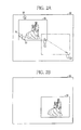
- the position of the second touch operation is moved from (2) to (3) so as to traverse the still image 32, being the object of editing, while the position of the first touch operation is fixed.
- the touch panel 12 detects this movement of the touch position, the still image 32, being the object of editing, is cropped.
- the display controller 26 measures speed of the finger traversing the still image 32 from (2) to (3), to determine whether the speed is faster than a predetermined value or not. As shown in Fig. 6B , when the display controller 26 determines that the traversing speed is faster than the predetermined value, the display controller 26 cuts off an area on the opposite side of a side pressed by the first touch operation with respect to a boundary for cropping (cropping line) that is the straight line indicated by the assistance line 37.
- the display controller 26 uses the trajectory of the second touch operation traversed as the boundary for cropping. As shown in Fig. 7B , the display controller 26 cuts off an area on the opposite side of the side pressed by the first touch operation with respect to the boundary.
- a desired area in the still image 32 displayed on the LCD 11 is cut off by requesting the execution of the cropping function and performing the second touch operation so as to traverse the still image 32, being the object of editing.
- the area of the still image 32, on the side of the first touch operation, is remained, so that it is not necessary to select which side of the traversed area to be remained with respect to the boundary for cropping.
- This operation is similar to cutting paper with a cutter or the like. It is easy for a user to learn the operation and crop an image even if he/she is not accustomed to the operation.
- the traversing speed time between the beginning and the end of traversing the still image 32 is obtained.
- the size of the still image 32 in the traversing direction is divided by the above-described time.
- the traversing time itself can be used as a criterion.
- cropping may be performed using the linear assistance line 37 as the boundary.
- cropping may be performed using the trajectory as the boundary. Similar to each of the above-described functions, the cropping function can be executed even if the still images are displayed on the screen 30.
- the execution of the guide line display function is requested by the second touch operation on a still image 32b after the touch operation on a still image 32a.
- the judgment section 25 determines that the execution of the guide line display function on the still image 32, being the object of editing, is requested.
- the display controller 26 displays four linear guide lines 38a to 38d along the still image 32a.
- the guide lines 38a to 38d are in contact with the respective sides of the rectangular still image 32.
- the guide lines 38a to 38d extend across the screen 30.
- the display controller 26 displays the guide line 38
- the touch panel 12 detects the operation to move the position of the first or second touch operation on the screen 30 while pressing is maintained
- the display controller 26 moves the touched still images 32a or 32b.
- the four guide lines 38a to 38d move together with the still image 32a.
- the display controller 26 moves the still image 32b.
- the still image 32b is attracted by the guide line 38b and stops its movement.
- an amount of movement in a direction orthogonal to the guide line 38b exceeds a predetermined amount, the still image 32b separates from the guide line 38b and starts moving.
- the still image 32b moves along the guide line 38b in the horizontal direction in accordance with the movement of the position of the touch operation in a manner similar to the normal operation.
- the still image 32b does not move in the vertical direction unless the position of the touch operation is moved by an amount greater than or equal to the predetermined amount.
- the still images 32a and 32b are arranged easily and neatly in the horizontal, vertical, or oblique direction (a direction parallel to the diagonal line of the still image 32a on which the first touch operation is performed) by moving the still image 32b along the guide line 38b.
- the judgment section 25 determines that the execution of the move function is requested when the touch panel 12 detects that the operation to move the first touch position is performed after the first touch operation is performed.
- the judgment section 25 determines that which of the magnification function, the rotation function, the cropping function, and the guide line display function is requested based on how the second touch operation is performed while the first touch operation is performed.
- the display controller 26 edits the image based on the result of the determination of the judgment section 25 and how the touch operation is performed which is detected by the touch panel 12 after the determination.
- the display controller 26 displays the edited image on the LCD 11.
- the above-described editing functions may be performed simultaneously.
- the still image, being the object of editing may be enlarged while being moved.
- the still image, being the object of editing may be rotated while being enlarged or reduced.
- the size and an angle may be changed simultaneously.
- only the first editing function determined after the still image is designated as the object of editing by the first touch operation may be executed.
- a mode for executing the editing functions simultaneously and a mode for executing only a single editing function may be provided. Each of the modes may be selected as necessary.
- Fig. 9 to create a photobook using the image editing apparatus 10, first, the recording medium 21 in which the still image data 22 is stored is attached to the media slot of the media controller 17. Then, the predetermined touch operation is performed on the touch panel 12 to command the CPU 13 of the image editing apparatus 10 to create the photobook.
- the CPU 13 accesses the recording medium 21 through the media controller 17, and takes the still image data 22, stored in the recording medium 21, into the system memory 14. After taking in the still image data 22, the CPU 13 produces thumbnail images from the still image data 22.
- the CPU 13 arranges and displays the thumbnail images on the LCD 11 to allow selection of the still images 32 to be displayed on the first page of the photobook. By touch-operating one or more thumbnail images corresponding to the still images 32 to be displayed on the first page, the still images 32 are selected.
- the CPU 13 After selecting the still images 32, the CPU 13 starts processes to allow selection of whether to use a decorative frame for decorating a peripheral portion of a page of the photobook and a type of the decorative frame.
- Data of the decorative frames is stored in the system memory 14 in advance.
- the CPU 13 produces the thumbnail images corresponding to the respective decorative frames from the data of the decorative frames stored in the system memory 14.
- Each of the thumbnail images is arranged and displayed on the LCD 11 to allow selection of whether to use the decorative frame and a type of the decorative frame.
- the CPU 13 After selecting the decorative frame, the CPU 13 allows the LCD 11 to display the selected still image 32. When the use of the decorative frame is selected, the selected decorative frame is displayed on the LCD 11 together with the still image 32. Thereafter, the CPU 13 starts image editing processes. By editing the still image 32 displayed on the LCD 11, the layout of the first page of the photobook is determined.
- the processes of the above-described editing functions are executed repeatedly in accordance with the commands of the touch operations until the end of the editing is commanded by a touch operation of a predetermined icon, or the like.
- the CPU 13 temporarily stores data (hereinafter referred to as the edit data), which is the layout result of the page 1 of the photobook produced after the above-described processes, in the system memory 14.
- the edit data refers to the data that reproduces the layout of the edited page, and stores still image data 22 and the type of the decorative frame selected, and the result of editing the still image 32, for example.
- the CPU 13 After storing the edit data in the system memory 14, the CPU 13 allows the LCD 11 to display a selection screen on which an icon for commanding creation of the next page and an icon for commanding not to create the next page are displayed. One of the icons is touch-operated to select whether the next page is created.
- the CPU 13 allows the LCD 11 to arrange and display the thumbnail images again.
- the thumbnail images correspond to respective pieces of the still image data 22 taken into the system memory 14.
- the CPU 13 When commanded not to create the next page, the CPU 13 converts each of the edit data stored in the system memory 14 into the print data compliant with a model of the printer 23. The CPU 13 outputs the print data to the printer 23 through the output I/F 18 and thereby allows the printer 23 to print.
- the still image 32, the decorative frame, and the like laid out as desired are printed on a printing medium.
- the printing media are bound into a book. Thus, the photobook is created.
- the CPU 13 prints each of the edit data, and also stores each of the edit data in the recording medium 21 to allow a customer to bring each of the edit data home.
- the CPU 13 may virtually print each of the edit data to convert the edit data into image data, and store each of the image data in the recording medium 21 together with each of the edit data. Thereby, the customer who brought the data home can reproduce the image data using a photoframe or the like to enjoy the photobook as an electronic album.
- the CPU 13 uses the detection function of the touch panel 12 to determine whether the touch operation is performed on the still image 32 displayed on the LCD 11.
- the CPU 13 designates the still image 32 as the object of editing.
- the CPU 13 allows the judgment section 25 to start determining whether the execution of various editing functions is requested.
- the CPU 13 allows the display controller 26 to display the icons 34, 35, and 36 for the still image 32, being the object of editing.
- the judgment section 25 determines that the execution of the move function is requested when the position of the touch operation on the still image 32 is moved while the touch operation is performed on the still image 32. Thereby, the display controller 26 starts a process of the move function.
- the display is controlled such that the still image 32 is moved in accordance with the position of the touch operation (see Figs. 2A and 2B ).
- the process of the move function is continued until the touch operation on the still image 32, being the object of editing, is cancelled.
- the second touch operation is performed on the still image 32 while the first touch operation is performed on the still image 32.
- the position of the second touch operation is moved while the position of the first touch operation is fixed so as to change a distance between each of the touch operations.
- the judgment section 25 determines that the execution of the magnification function is requested. Thereby, the display controller 26 starts a process of the magnification function.
- a magnification for enlargement or reduction is calculated from the touch position of the second touch operation and the position after the movement.
- the display is controlled so as to enlarge or reduce the still image 32, being the object of editing, in accordance with the magnification (see Figs. 3A and 3B ).
- the process of the magnification function is continued until the first touch operation on the still image 32, being the object of editing, is cancelled.
- the second touch operation is performed on the still image 32 while the first touch operation on the still image 32 is performed.
- the position of the second touch operation is moved in arc around the position of the first touch operation while the position of the first touch operation is fixed.
- the judgment section 25 determines that the execution of the rotation function is requested and the display controller 26 starts a process of the rotation function.
- an angle of rotation is calculated from the position of the second touch operation and the position of the touch operation after the movement.
- the display is controlled to rotate the still image 32, being the object of editing, by the angle calculated (see Figs. 4A and 4B ).
- the process of the rotation function is continued until the first touch operation on the still image 32, being the object of editing, is cancelled.
- the judgment section 25 determines that the execution of the cropping function is requested when the second touch operation is performed on a blank space while the first touch operation is performed on the still image 32, and the display controller 26 starts the process of the cropping function.
- the blank space is an area outside of the still image 32 and in which no other still image 32 is displayed.
- the assistance line 37 is displayed on the LCD 11 (see Figs. 5A and 5B ).
- the position of the second touch operation is moved to traverse the still image 32, being the object of editing, while the position of the first touch operation fixed, it is determined whether the traversing speed is faster than a predetermined value or not.
- the cropping process is performed using a straight line, indicated by the assistance line 37, as the boundary for cropping (see Figs. 6A and 6B ).
- the cropping process is performed using a trajectory of the second touch operation traversed (see Figs. 7A and 7B ). The process of the cropping function is continued until the first touch operation on the still image 32, being the object of editing, is cancelled.
- the judgment section 25 determines that the execution of the guide line display function is requested, and the display controller 26 starts a process of the guide line display function.
- the four linear guide lines 38a to 38d corresponding to the still image 32a, being the object of editing are displayed on the LCD 11 (see Fig. 8A ).
- the display is controlled such that the still images 32a and 32b are moved in accordance with the movements of the touch operations in a manner similar to the move function.
- the display is controlled such that the side of the still image 32b is attracted by the guide line 38 (see Fig. 8B ).
- the process of the guide line display function is continued until the first touch operation on the still image 32a, being the object of editing, is cancelled.
- the move function is executed by moving the position of the touch operation on the still image.
- the second touch operation By performing the second touch operation while the first touch operation is performed on the still image, one of the magnification function, the rotation function, the cropping function, and the guide line display function is executed in accordance with how the second touch operation is performed.
- the still image is edited only with intuitive operation that is the touch operation on the screen 30.
- the operability in editing the still image on the screen 30 is improved significantly. Editing the still image only with the intuitive operation allows a user to easily understand how to operate each of the editing functions. Hence, even the user not accustomed to the operation can create an attractive photobook easily.
- a function to display a text input box 40, in which a character string is inputted, on the LCD 11 during the image editing processes may be provided to lay out a desired character string in a desired position on a page of the photobook. It is more preferable that the text input box 40 is handled in a manner similar to the still image 32 such that the text input box 40 is edited using each of the editing functions (magnification, rotation, and the like) in steps similar to those for the still image 32.
- the second touch operation is performed within the still image, being the object of editing.
- the second touch operation may be performed on the blank space outside of the still image, being the object of editing.
- the assistance line 37 parallel with the horizontal or vertical direction of the screen 30 is displayed when the cropping function is executed.
- the assistance line 37 is not displayed when the second touch operation is performed in an oblique direction outside of the still image 32.
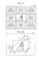
- the blank space surrounding the still image 32 is divided into rectangular areas, and each area may be used as a selection button for specific editing functions.
- the blank spaces on the top, bottom, left and right of the still image 32 function as the selection buttons for cropping.
- the judgment section 25 determines that the execution of the cropping function is requested.
- the blank spaces located in oblique directions outside of the still image 32 function as the selection buttons for magnification and rotation.
- the judgment section 25 determines that the execution of the rotation function is requested when the position of the second touch operation is moved in arc. Thus, the judgment section 25 properly determines the request of execution of the magnification function and that of the rotation function even if the execution of the magnification function and the execution of the rotation function can be requested by performing the second touch operation on the blank space outside of the still image 32, being the object of editing.
- the assistance line 37 parallel with the horizontal or vertical direction of the screen 30 is displayed when the cropping function is executed.
- the position of the second touch operation is moved to traverse the still image 32 at the speed faster than the predetermined value, the cropping is performed using the assistance line 37 as the boundary.
- the linear boundary can be set only in the horizontal or vertical direction.
- the linear boundary may be set at a desired angle by tilting the assistance line 37 at the desired angle.
- a position of the second touch operation outside of the still image 32, being the object of editing is set as a starting point.
- a line segment between the starting point and the position of the second touch operation after the movement is determined.
- the line segment is extended and displayed as an assistance line 42.
- the assistance line 42 is displayed at a desired angle in accordance with the movement of the second touch operation.
- the display controller 26 uses the assistance line 42 as the boundary.
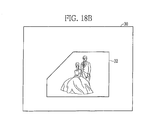
- the linear boundary at a desired angle is set.
- the display controller 26 uses the straight line, indicated by the assistance line 42, as the boundary for cropping, and cuts off an area on the opposite side of the side pressed by the first touch operation with respect to the boundary.
- the trajectory of the position of the touch operation is used as the boundary for cropping.
- an angle of the assistance line 42 is notified using a numeric display 44.
- the angle may be notified using an icon in a shape of a protractor, for example.
- the linear boundary may be set using a least square method, for example. Thereby, an approximation straight line of the trajectory of the second touch operation is calculated and set as the linear boundary.
- each of the linear guide lines 38a to 38d extends across the screen 30.
- each of the guide lines 38a to 38d may not extend across the screen 30.
- the four guide lines 38a to 38d in contact with the respective sides of the still image 32 are shown.
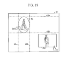
- the shape of the still image may not necessarily be rectangular because the still image can be cropped into a desired shape.
- the guide lines corresponding to the respective sides of the pentagonal still image 32 are used. Each guide line is displayed so as to come in contact with the corresponding side.
- two guide lines 46a and 46b, parallel with the horizontal direction of the screen 30, are laid out so as to be in contact with upper and lower edges of a still image 32c, respectively, and two guide lines 46c and 46d, parallel with the vertical direction of the screen 30, are laid out so as to be in contact with left and right edges of the still image 32c, respectively, for example.
- the still images are neatly aligned in the horizontal and vertical directions regardless of the shapes of the still images.
- a side of the still image 32b is attracted by the guide line 38b.
- an apex of a polygonal shape or a part of a curve may be attracted by the guide line.
- a type of the guide line to be displayed may be set as necessary when the execution of the guide line display function is requested.
- FIGs. 20A and 20B illustrate the touch operation with one hand.
- a pointer 48 being a mark indicating a position of the first touch operation, is displayed on the LCD 11 as shown in Fig. 20B .
- the judgment section 25 and the display controller 26 determine that the first touch operation is maintained while the pointer 48 is displayed.
- the judgment section 25 determines that the second touch operation is performed when a touch operation is detected by the touch panel 12 while the pointer 48 is displayed.
- the second touch operation is performed in a state that the first touch operation is stopped.
- the operation is performed with one hand, making the operation easy.
- any mark for example, a pin, a thumbtack, an arrow, a hand or a finger, or a letter which indicates a position of the first touch operation may be used.
- the first touch operation is cancelled by deleting the pointer 48.
- the cancellation is commanded by touch-operating a cancel icon or by touch-operating the pointer 48. Thereby, the pointer 48 is deleted.
- the move function, the magnification function, the rotation function, the cropping function, and the guide line display function are provided as the editing functions, which are determined by the judgment section 25. Only one of these functions may be provided. Additional editing functions may be provided.
- the still image data 22 is taken in from the recording medium 21.
- the still image data 22 may be taken in through a network such as the Internet or LAN.
- a modem or a router for accessing the network is used as an image input section.
- the LCD 11 is used as a display section.
- a well-known display such as an organic EL display or a plasma display can be used as the display section.
- the image editing apparatus 10 for creating photobook is described by way of example. The present invention is employed when a still image is edited on a screen of a personal computer, a mobile phone (smartphone), a digital camera, or a digital audio player, for example.
Landscapes
- Engineering & Computer Science (AREA)
- Theoretical Computer Science (AREA)
- General Engineering & Computer Science (AREA)
- General Physics & Mathematics (AREA)
- Physics & Mathematics (AREA)
- Human Computer Interaction (AREA)
- Signal Processing (AREA)
- Multimedia (AREA)
- User Interface Of Digital Computer (AREA)
- Processing Or Creating Images (AREA)
- Editing Of Facsimile Originals (AREA)
- Studio Devices (AREA)
- Facsimiles In General (AREA)
Abstract
Description
- The present invention relates to an image editing method and an image editing apparatus, and an image editing program for editing a still image on a screen of a display section.
- A photobook in which still images, captured with a digital camera or the like, are laid out like an album is known. The photobook can be viewed as an electronic album when the laid out still images are outputted to a display device. The photobook can be viewed as an ordinary photo album when the still images are printed on a printing medium such as paper.
- As described in
patent documents - Processing the still images makes the photobook highly attractive as compared with a photo album or an electronic album in which the photographs or still images are just laid out. Hence the photobook is useful in keeping still images for commemoration or as a gift.
- The image editing apparatus is installed in a photo development shop or the like. A shop clerk operates the image editing apparatus at a customer's request or a customer him/herself operates the image editing apparatus to create a desired photobook. There have been cases where a customer or even a shop clerk was not accustomed to operation of the image editing apparatus with many functions and took a long time to create a photobook. It is desired to improve operability of the image editing apparatus to allow the shop clerk or the customer who are not accustomed to the operation to create an attractive photobook easily.
- For example, the
patent document 1 discloses that an attractive photobook is created easily by grouping still images according to directions of eyes of subjects and automatically arranging the still images such that the eyes of the subjects are directed to the center of two facing pages. Thepatent document 2 discloses that a sensor distinguishes between users who selected images. Thereby, operability is improved when still images are selected by users simultaneously. - The
patent document 2 discloses that a touch panel is used as a device for inputting an operation. The touch panel allows intuitive operation such as touching an icon or the like on a screen with a finger or an exclusive pen to provide input. Hence, it is easy for even an inexperienced user to understand the operation. Operability is improved as compared with the case where a pointing device such as a mouse is used. -
- PATENT DOCUMENT 1 : Patent Laid-Open Publication No.
2009-238162 - PATENT DOCUMENT 2: Patent Laid-Open Publication No.
2009-244725 - When the image editing apparatus with the touch panel is used, desired editing functions are set by operating icons corresponding to the respective editing functions or by selecting menu items corresponding to the respective editing functions from a menu list. Operations corresponding to the selected functions are performed on the still image, being an object. Thus, the still image is edited. However, this operation method requires setting of the editing functions, and is not easy for a user not accustomed to the operation because the setting operation is bothersome, the icons and menu items to be used are difficult to find, and the like.
- As described above, in the present situation, even the image editing apparatus with the touch panel lacks consideration on an operation method for editing a still image. Hence, it is desired that the operation of editing a still image on the screen of the image editing apparatus with the touch panel to be more intuitive.
- An object of the present invention is to edit a still image with intuitive operation to improve operability.
- In order to achieve the above object, an image editing apparatus of the present invention has editing functions to edit at least one still image on a screen of a display section and is provided with a touch panel, a judgment section, and a display controller. The touch panel is provided over the screen. The touch panel detects a position of a touch operation when the position over the screen is pressed by the touch operation. The judgment section determines which of the editing functions is requested to be executed. When a second touch operation is performed after a first touch operation is performed on a portion of the still image on the screen, the judgment section determines the editing function requested to be executed, in accordance with how the second touch operation is operated. The display controller controls a display on the display section. The display controller executes the editing function determined by the judgment section.
- The judgment section determines that the second touch operation is performed when the touch operation is performed on another position while the first touch operation on the still image is maintained.
- The display controller displays a mark indicating a position of the first touch operation on the display section when the first touch operation is stopped after the first touch operation is performed on the still image. The judgment section determines that the second touch operation is performed when the touch operation is performed while the mark is displayed.
- One of the editing functions is a cropping function to cut off a part of the still image. The judgment section determines that execution of the cropping function on the still image is requested when the second touch operation is performed outside of the still image after the first touch operation is performed on the portion of the still image. After the judgment section determines that the execution of the cropping function is requested, the display controller cuts off the still image along the boundary when the position of the second touch operation is moved to traverse the still image. The boundary is set based on a trajectory of the second touch operation.
- The display controller determines whether a speed for traversing the still image is faster than a predetermined value or not. When the display controller determines that the speed is faster than the predetermined value, the display controller sets a straight line corresponding to the trajectory as the boundary. When the display controller determines that the speed is slower than the predetermined value, the display controller sets the trajectory itself as the boundary.
- It is preferable that the display controller cuts off an area on opposite side of the first touch operation with respect to the boundary.
- It is preferable that the display controller displays an assistance line on the screen when the execution of the cropping function is requested. The assistance line helps to indicate the boundary.
- One of the editing functions is a guide line display function to display a guide line to neatly align at least a first still image and a second still image. The judgment section determines that execution of the guide line display function on the first still image is requested when the second touch operation is performed on the second still image after the touch operation is performed on a portion of the first still image. When the judgment section determines that the execution of the guide line display function is requested, the display controller displays the first still image along the guide line.
- One of the editing functions is a magnification function to enlarge or reduce the still image to a desired size. The judgment section determines that execution of the magnification function on the still image is requested when the position of the second touch operation is moved relative to the position of the first touch operation such that the distance between the position of the first touch operation and the position of the second touch operation is widened and narrowed. When the judgment section determines that the execution of the magnification function is requested, the display controller obtains a magnification for enlargement or reduction based on a ratio between a distance from the position of the first touch operation to the position of the second touch operation before the movement and a distance from the position of the first touch operation to the position of the second touch operation after the movement. The display controller enlarges or reduces the still image with the magnification, using the position of the first touch operation as a center point.
- One of the editing functions is a rotation function to rotate the still image at a desired inclination. The judgment section determines that execution of the rotation function on the still image is requested when the position of the second touch operation is moved in arc around the position of the first touch operation. When the judgment section determines that execution of the rotation function is requested, the display controller obtains an angle between two line segments. An end of each of the line segments is the position of the first touch operation. The other end of one of the line segments is the position of the second touch operation before the movement. The other end of the other line segment is a position of the second touch operation after the movement. The still image is rotated by the angle about the position of the fist touch operation.
- It is preferable that the display controller displays an icon indicating the next operable editing function on the screen when the touch operation is performed on the portion of the still image.
- An image editing method of the present invention selectively executes editing functions using an image editing apparatus for editing at least one still image on a screen of a display section. The image editing apparatus has a touch panel that detects a touch position over the screen. The image editing method has a determining step and a display controlling step. The determining step determines which of the editing functions is requested to be executed. When the second touch operation is performed after the first touch operation is performed on a portion of the sill image on the screen, the determining step determines the editing function requested to be executed, in accordance with how the second touch operation is performed. The display controlling step controls a display on the display section. The display controlling step executes the editing function determined by the judgment section.
- An image editing program of the present invention allows an image editing apparatus to selectively execute editing functions. The image editing apparatus edits at least one still image on a screen of a display section. The image editing apparatus has a touch panel that detects a touch position over the screen. The image editing program has a determining process and a display controlling process. The determining process determines which of the editing functions is requested to be executed. When the second touch operation is performed after the first touch operation is performed on a portion of the still image on the screen, the determining process determines the editing function requested to be executed, in accordance with how the second touch operation is performed. The display controlling process controls a display on the display section. The display controlling process executes the editing function determined by the judgment section.
- In the present invention, when the touch operations are performed with fingers on two points on the still images on the screen, the type of the editing function is determined and executed in accordance with how the second touch operation is performed. Thereby, the still image is edited only with the intuitive operation, that is, the touch operation on the screen. There is no need to operate an icon or a menu item in editing the still image. Thus, the operability in editing the still image on the screen is improved significantly.
-
-
Fig. 1 is a block diagram schematically illustrating a configuration of an image editing apparatus. -
Fig. 2A is an explanatory view illustrating how a move function is operated. -
Fig. 2B is an explanatory view illustrating a result of operation of the move function. -
Fig. 3A is an explanatory view illustrating how a magnification function is operated. -
Fig. 3B is an explanatory view illustrating a result of operation of the magnification function. -
Fig. 4A is an explanatory view illustrating how a rotation function is operated. -
Fig. 4B is an explanatory view illustrating a result of operation of the rotation function. -
Fig. 5A is an explanatory view illustrating an example of displaying a vertical assistance line of a cropping function. -
Fig. 5B is an explanatory view illustrating an example of displaying a horizontal assistance line of the cropping function. -
Fig. 6A is an explanatory view illustrating how a cropping operation is performed using the assistance line as a boundary. -
Fig. 6B is an explanatory view illustrating a result of the cropping operation using the assistance line as a boundary. -
Fig. 7A is an explanatory view illustrating how the cropping operation is performed using a trajectory as the boundary. -
Fig. 7B is an explanatory view illustrating a result of the cropping operation using the trajectory as the boundary. -
Fig. 8A is an explanatory view illustrating an example of displaying a guide line of a guide line display function. -
Fig. 8B is an explanatory view illustrating the still image attracted by the guide line. -
Fig. 9 is a flowchart illustrating steps for operating the image editing apparatus. -
Fig. 10 is a flowchart illustrating steps for image editing processes. -
Fig. 11 is a flowchart illustrating steps for a process of the move function. -
Fig. 12 is a flowchart illustrating steps for a process of the magnification function. -
Fig. 13 is a flowchart illustrating steps for a process of the rotation function. -
Fig. 14 is a flowchart illustrating steps for a process of the cropping function. -
Fig. 15 is a flowchart illustrating steps for a process of the guide line display function. -
Fig. 16 is an explanatory view illustrating an example of displaying a text input box. -
Fig. 17 is an explanatory view illustrating an example of displaying an edit menu. -
Fig. 18A is an explanatory view illustrating how cropping is performed along a straight line at a given angle. -
Fig. 18B is an explanatory view illustrating a result of operation of the cropping at the given angle. -
Fig. 19 is an explanatory view illustrating an example of displaying guide lines along a still image of a given shape. -
Fig. 20A is an explanatory view of an example of displaying a pointer at a position of a first touch operation. -
Fig. 20B is an explanatory view of an example of displaying the pointer. - As shown in
Fig. 1 , animage editing apparatus 10 is provided with anLCD 11 and atouch panel 12. Theimage editing apparatus 10 displays various operation screens and the like for editing a still image 32 (seeFig. 2 ) on theLCD 11. As is well known, when an operation to press a surface of thetouch panel 12 with a finger or an exclusive pen is performed (hereinafter, this operation is referred to as the touch operation), thetouch panel 12 detects the position of the touch operation. Thetouch panel 12 is a transparent sheet attached over a screen 30 (seeFig. 2 ) of theLCD 11. The size of thetouch panel 12 is substantially the same as that of thescreen 30. Thetouch panel 12 covers theentire screen 30 in a transparent manner. When the touch operations are performed over positions on thescreen 30, thetouch panel 12 detects the positions of the respective touch operations simultaneously. - The
image editing apparatus 10 performs various processes on thestill image 32 displayed on theLCD 11, and edits thestill image 32 on thescreen 30 of theLCD 11. Thereby, theimage editing apparatus 10 creates a photobook in which the stillimages 32 are laid out like an album. In theimage editing apparatus 10, thetouch panel 12 is provided over thescreen 30 of theLCD 11. Thereby, various operations necessary for creating the photobook, for example, editing thestill image 32, are performed by intuitive operation, namely, by pressing thescreen 30 with the finger or the exclusive pen. - The
image editing apparatus 10 is provided with aCPU 13, asystem memory 14, anLCD driver 15, atouch panel driver 16, amedia controller 17, and an output interface (I/F) 18, in addition to theLCD 11 and thetouch panel 12. Each section is mutually connected through abus 20. - The
system memory 14 has a ROM area and a RAM area, as is well known. The ROM area stores aprogram 14a corresponding to various processes of theimage editing apparatus 10 and various types of data necessary for the processes of theprogram 14a. The RAM area temporarily stores various types of data produced during the process of theprogram 14a, and the like. TheCPU 13 reads out theprogram 14a from thesystem memory 14, and executes theprogram 14a sequentially. Thereby, theCPU 13 controls each section of theimage editing apparatus 10. - The
LCD driver 15 controls the operation of theLCD 11. TheLCD driver 15 outputs an image signal, corresponding to a command from theCPU 13, to theLCD 11. Thereby, theLCD driver 15 allows the screen of theLCD 11 to display various images such as an operation screen. Thetouch panel driver 16 controls operation of thetouch panel 12. When thetouch panel 12 detects a position of the touch operation, thetouch panel driver 16 converts a detected result indicating the position of the touch operation into an electric signal and inputs the electric signal to theCPU 13. - The
media controller 17 has a media slot that detachably holds arecording medium 21. In response to a command from theCPU 13, themedia controller 17 accesses therecording medium 21 attached to the media slot, and writes and reads data to and from therecording medium 21. TheCPU 13 accesses therecording medium 21 through themedia controller 17 when theCPU 13 takes in still image data for creating a photobook from therecording medium 21 and writes data of a created photobook to therecording medium 21, for example. - Note that the
recording medium 21 may be a well-known medium such as a USB memory or an SD card. Themedia controller 17 compliant with the standard of therecording medium 21 is employed as necessary. Themedia controller 17 may be compatible with various types ofrecording media 21 and capable of reading and writing data to and from each of therecording media 21. - The output I/
F 18 has a connector into which an end of a cable is fitted. The cable connects theimage editing apparatus 10 and aprinter 23. Through the connector and the cable, the output I/F 18 is electrically connected to theprinter 23. In response to a command from theCPU 13, the output I/F 18 outputs print data to theprinter 23. Thereby, the output I/F 18 allows theprinter 23 to print based on the print data. - The
CPU 13 produces the print data, compliant with a model of theprinter 23, from the data of the created photobook, for example. TheCPU 13 outputs the print data to theprinter 23 through the output I/F 18. Thereby, the data of the photobook is printed on a printing medium and thus the photobook is completed. Note that theprinter 23 is a well-known printer, for example, an inkjet printer that deposits ink on coated paper to produce an image or a photographic printer that exposes photographic paper to produce an image. - The
CPU 13 is provided with ajudgment section 25 and adisplay controller 26. Based on the result of detection of the touch operation on thetouch panel 12, thejudgment section 25 determines whether execution of various editing functions for editing thestill image 32 displayed on theLCD 11 is requested. Thedisplay controller 26 executes a requested editing function (image processing) in accordance with how the touch operation is performed on thetouch panel 12 and a result of the determination of thejudgment section 25. - The editing functions executed by the
display controller 26 include a move function, a magnification function, a rotation function, a cropping function, and a guide line display function. The move function is a function to move thestill image 32 to a desired position on thescreen 30. The magnification function is a function to enlarge or reduce the size of thestill image 32 as desired. The rotation function is a function to rotate thestill image 32 at a desired inclination. The cropping function is a function to cut off a part of thestill image 32. The guide line display function is a function to display guide line(s) to align the stillimages 32 neatly. The predetermined touch operations corresponding to the respective editing functions are performed on thetouch panel 12. Thereby, thedisplay controller 26 requests the execution of each editing function. - As shown in
Fig. 2 , to request the execution of each editing function, first, a portion of thestill image 32, displayed on theLCD 11, is touch-operated through thetouch panel 12. Thereby, thestill image 32 is designated as an object of editing. When theCPU 13 receives the detection result of thetouch panel 12 from thetouch panel driver 16, thedisplay controller 26 compares the image on theLCD 11 and the detection result. From the result of the comparison, theCPU 13 determines whether the detected touch operation is performed on thestill image 32. Upon determining that the touch operation is performed on thestill image 32, theCPU 13 designates thestill image 32 as the object of editing. - The
CPU 13 maintains the designation of thestill image 32 as the object of editing while the touch operation is performed. When the touch operation is cancelled, theCPU 13 cancels the designation of thestill image 32 as the object of editing. - In response to the designation of the
still image 32 as the object of editing by theCPU 13, thejudgment section 25 starts a process to determine whether the execution of various editing functions is requested. After the designation of the object of editing, thedisplay controller 26 displays amagnification icon 34, arotation icon 35, and acrop icon 36 on theLCD 11. Themagnification icon 34 indicates that the magnification function is operable. Therotation icon 35 indicates that the rotation function is operable. Thecrop icon 36 indicates that the cropping function is operable. - The
display controller 26 displays theicons still image 32 in a right-left direction, on thescreen 30. At this time, thedisplay controller 26 displays themagnification icon 34 and therotation icon 35 in a corner portion within thestill image 32 designated as the object of editing. Thedisplay controller 26 displays thecrop icon 36 outside of and close to thestill image 32. Hence, as shown inFig. 2A , when the touch operation is performed on a rightward position in thestill image 32, themagnification icon 34 and therotation icon 35 are displayed in a lower left corner portion or an upper left corner portion of thestill image 32. Thecrop icon 36 is displayed outside of and close to a leftward end of thestill image 32. - As shown in
Fig. 2A , to move the image, the touch operation is performed on thestill image 32 and then the position of the touch operation is moved on thescreen 30 while thestill image 32 is pressed through thetouch panel 12. When the above operation is detected by thetouch panel 12, thejudgment section 25 determines that the execution of the move function on thestill image 32, being the object of editing, is requested. Note that numbers in parentheses in the drawing schematically show the order of the touch operations. - When the
judgment section 25 determines that the execution of the move function is requested, a position of the first touch operation on thestill image 32, being the object of editing, is set as a reference point. As shown inFig. 2B , thedisplay controller 26 moves thestill image 32 such that the reference point is moved to a position of the touch operation after the movement. Thereby, thestill image 32 displayed on theLCD 11 is moved to a desired position on thescreen 30 by requesting the execution of the move function. - Note that in
Figs. 2A and 2B , it seems as if thestill image 32 moves intermittently from the starting point to the end point of a trajectory of the touch operation. Actually, thestill image 32 moves continuously in accordance with the movement of the touch operation. Only one stillimage 32 is displayed on thescreen 30 of theLCD 11. As a matter of course, the move function is executed when still images are displayed on thescreen 30. When one of the still images is moved and overlapped onto another still image, thedisplay controller 26 overlaps and displays the still images such that the moved still image, being the object of editing, is placed in front of (on top of) the other still image. - As shown by (1) in
Fig. 3A , to request the execution of the magnification function, a first touch operation is performed on thestill image 32. Then, as shown by (2), a second touch operation is performed on thestill image 32 while the position of the first touch operation is fixed. In this state, the position of the second touch position is moved to a position shown by (3), and a distance between the position of the first touch operation and the position of the second touch operation is widened and narrowed. Thejudgment section 25 determines that the execution of the magnification function on thestill image 32, being the object of editing, is requested when the above-described operation is detected by thetouch panel 12, - The
magnification icon 34 is displayed within thestill image 32, being the object of editing. A mark of a linear two-way arrow, indicating directions in which the position of the second touch position is moved, helps to show how the above-described operation for requesting the magnification function is performed. - When the
judgment section 25 determines that the execution of the magnification function is requested, thedisplay controller 26 obtains a magnification for enlargement or reduction from a distance between (1) and (2) and a distance between (1) and (3). As shown inFig. 3B , thedisplay controller 26 sets the position of the first touch operation as the reference point, and enlarges or reduces thestill image 32, being the object of editing, by the magnification obtained. - Thus, the execution of the magnification function is requested. By widening the distance between the respective touch operations, the
still image 32 displayed on theLCD 11 is enlarged to a desired size. By narrowing the distance between the respective touch operations, thestill image 32 is reduced to a desired size. - Note that, in the case of the magnification function, the
still image 32 is enlarged or reduced continuously in accordance with the movement of the second touch operation, in a manner similar to the move function. The magnification function can be executed in a state where the still images are displayed on thescreen 30, in a manner similar to the move function. When the still image is enlarged by executing the magnification function and overlaps another still image, the still images may be overlapped and displayed such that the enlarged still image, being the object of editing, is displayed in front (on top), in a manner similar to the move function. Alternatively, the other still image may be shifted so as not to overlap the enlarged still image, being the object of editing. - As shown by (1) in
Fig. 4A , to request the execution of the rotation function, the first touch operation is performed on thestill image 32. Then, the second touch operation, shown by (2), is performed on thestill image 32 while the position of the first touch operation is fixed. In this state, the position of the second touch operation is moved in arc around (1) until the position of the second touch operation reaches a position shown by (3). When the above-described operation is detected by thetouch panel 12, thejudgment section 25 determines that the execution of the rotation function on thestill image 32, being the object of editing, is requested. - The
rotation icon 35 is displayed within thestill image 32, being the object of editing. A mark of an arc-shaped two-way arrow, indicating the movement of the second touch position, helps to show how the above-described operation for requesting the rotation function is performed. - When the
judgment section 25 determines that the execution of the rotation function is requested, thedisplay controller 26 obtains an angle between a line segment between (1) and (2) and a line segment between (1) and (3). As shown inFig. 4B , thedisplay controller 26 rotates thestill image 32, being the object of editing, about the position of the first touch operation indicated by (1) by the angle obtained. - Thus, the
still image 32 displayed on theLCD 11 is rotated by a desired angle by requesting the execution of the rotation function and moving the position of the second touch operation in arc around the position of the first touch operation. Note that, in the case of the rotation function, thestill image 32 is rotated continuously in accordance with the movement of the second touch operation, similar to each of the above-described functions. - Similar to each of the above-described functions, the rotation function can be executed even if the still images are displayed on the
screen 30. When the rotation function is executed and the still image is rotated, the still image may overlap another still image. In this case, the still images may be overlapped and displayed such that the rotated still image, being the object of editing, is displayed in front (on top), in a manner similar to the magnification function. The other still image may be shifted so as not to overlap the rotated still image, being the object of editing. - As shown by (1) in
Fig. 5 , after the first touch operation is performed on thestill image 32, execution of the cropping function is requested by the second touch operation indicated by (2) performed in a blank space outside of thestill image 32 and not displaying any otherstill image 32. Thejudgment section 25 determines that the execution of the cropping function on thestill image 32, being the object of editing, is requested when thetouch panel 12 detects the above-described operation. - The
crop icon 36 is displayed outside of and close to thestill image 32, being the object of editing. Thecrop icon 36 is a mark of scissors that is associated with cropping, and thus helps to show how the above-described operation for requesting the cropping function is performed. Note that, other than the intuitive marks, each of theicons - When the
judgment section 25 determines that the execution of the cropping function is requested, thedisplay controller 26 displays anassistance line 37 that linearly traverses thestill image 32, being the object of interest, from the position of the second touch operation in a horizontal or vertical direction of thescreen 30. Theassistance line 37 helps to show the cropping line (boundary for cropping). - As shown in
Fig. 5A , thedisplay controller 26 displays thelinear assistance line 37 which traverses thestill image 32 in the vertical direction when the second touch operation is performed above or below thestill image 32, being the object of editing. As shown inFig. 5B , thedisplay controller 26 displays thelinear assistance line 37 which traverses thestill image 32 in the horizontal direction when the second touch operation is performed right or left to thestill image 32, being the object of editing. - When the
touch panel 12 detects the operation to move the position of the second touch operation outside thestill image 32, being the object of editing, in the horizontal or vertical direction, thedisplay controller 26 allows theassistance line 37 to follow the movement of the position of the second touch operation. For example, when the position of the second touch operation is moved in the horizontal direction after the second touch operation is performed above thestill image 32, being the object of editing, to display theassistance line 37 which traverses thestill image 32 in the vertical direction, theassistance line 37 displayed follows the movement in the horizontal direction. - As shown by (1) in
Fig. 6A , after theassistance line 37 is displayed, the position of the second touch operation is moved from (2) to (3) so as to traverse thestill image 32, being the object of editing, while the position of the first touch operation is fixed. When thetouch panel 12 detects this movement of the touch position, thestill image 32, being the object of editing, is cropped. - The
display controller 26 measures speed of the finger traversing thestill image 32 from (2) to (3), to determine whether the speed is faster than a predetermined value or not. As shown inFig. 6B , when thedisplay controller 26 determines that the traversing speed is faster than the predetermined value, thedisplay controller 26 cuts off an area on the opposite side of a side pressed by the first touch operation with respect to a boundary for cropping (cropping line) that is the straight line indicated by theassistance line 37. - As shown in
Fig. 7A , when thedisplay controller 26 determines that the traversing speed is slower than the predetermined value, thedisplay controller 26 uses the trajectory of the second touch operation traversed as the boundary for cropping. As shown inFig. 7B , thedisplay controller 26 cuts off an area on the opposite side of the side pressed by the first touch operation with respect to the boundary. - Thus, a desired area in the
still image 32 displayed on theLCD 11 is cut off by requesting the execution of the cropping function and performing the second touch operation so as to traverse thestill image 32, being the object of editing. The area of thestill image 32, on the side of the first touch operation, is remained, so that it is not necessary to select which side of the traversed area to be remained with respect to the boundary for cropping. This operation is similar to cutting paper with a cutter or the like. It is easy for a user to learn the operation and crop an image even if he/she is not accustomed to the operation. - Note that, to calculate the traversing speed, time between the beginning and the end of traversing the
still image 32 is obtained. The size of thestill image 32 in the traversing direction is divided by the above-described time. Alternatively, the traversing time itself can be used as a criterion. When the traversing time is shorter than a predetermined value, cropping may be performed using thelinear assistance line 37 as the boundary. When the traversing time is longer than the predetermined value, cropping may be performed using the trajectory as the boundary. Similar to each of the above-described functions, the cropping function can be executed even if the still images are displayed on thescreen 30. - As shown by (1) in
Fig. 8A , the execution of the guide line display function is requested by the second touch operation on astill image 32b after the touch operation on astill image 32a. When thetouch panel 12 detects the above-described operation, thejudgment section 25 determines that the execution of the guide line display function on thestill image 32, being the object of editing, is requested. - When the
judgment section 25 determines that the execution of the guide line display function is requested, thedisplay controller 26 displays fourlinear guide lines 38a to 38d along thestill image 32a. The guide lines 38a to 38d are in contact with the respective sides of the rectangularstill image 32. The guide lines 38a to 38d extend across thescreen 30. - After the
display controller 26 displays the guide line 38, when thetouch panel 12 detects the operation to move the position of the first or second touch operation on thescreen 30 while pressing is maintained, thedisplay controller 26 moves the touched stillimages still image 32a is moved, the fourguide lines 38a to 38d move together with thestill image 32a. - As shown in
Fig. 8B , thedisplay controller 26 moves thestill image 32b. When one side of thestill image 32b comes in contact with theguide line 38b, thestill image 32b is attracted by theguide line 38b and stops its movement. In this case, when an amount of movement in a direction orthogonal to theguide line 38b exceeds a predetermined amount, thestill image 32b separates from theguide line 38b and starts moving. - For example, as shown in
Fig. 8B , when an upper side of thestill image 32b is attracted by theguide line 38b, thestill image 32b moves along theguide line 38b in the horizontal direction in accordance with the movement of the position of the touch operation in a manner similar to the normal operation. On the other hand, thestill image 32b does not move in the vertical direction unless the position of the touch operation is moved by an amount greater than or equal to the predetermined amount. - Thus, when the guide line display function is executed, the still
images still image 32a on which the first touch operation is performed) by moving thestill image 32b along theguide line 38b. - As described above, the
judgment section 25 determines that the execution of the move function is requested when thetouch panel 12 detects that the operation to move the first touch position is performed after the first touch operation is performed. Thejudgment section 25 determines that which of the magnification function, the rotation function, the cropping function, and the guide line display function is requested based on how the second touch operation is performed while the first touch operation is performed. Thedisplay controller 26 edits the image based on the result of the determination of thejudgment section 25 and how the touch operation is performed which is detected by thetouch panel 12 after the determination. Thedisplay controller 26 displays the edited image on theLCD 11. - Note that the above-described editing functions may be performed simultaneously. For example, the still image, being the object of editing, may be enlarged while being moved. The still image, being the object of editing, may be rotated while being enlarged or reduced. Thus, the size and an angle may be changed simultaneously. Alternatively, only the first editing function determined after the still image is designated as the object of editing by the first touch operation may be executed. A mode for executing the editing functions simultaneously and a mode for executing only a single editing function may be provided. Each of the modes may be selected as necessary.
- Next, with reference to flowcharts in
Figs. 9 to 15 , operation of theimage editing apparatus 10 of the above configuration is described. As shown inFig. 9 , to create a photobook using theimage editing apparatus 10, first, therecording medium 21 in which thestill image data 22 is stored is attached to the media slot of themedia controller 17. Then, the predetermined touch operation is performed on thetouch panel 12 to command theCPU 13 of theimage editing apparatus 10 to create the photobook. When the creation of the photobook is commanded, theCPU 13 accesses therecording medium 21 through themedia controller 17, and takes thestill image data 22, stored in therecording medium 21, into thesystem memory 14. After taking in thestill image data 22, theCPU 13 produces thumbnail images from thestill image data 22. TheCPU 13 arranges and displays the thumbnail images on theLCD 11 to allow selection of the stillimages 32 to be displayed on the first page of the photobook. By touch-operating one or more thumbnail images corresponding to the stillimages 32 to be displayed on the first page, the stillimages 32 are selected. - After selecting the still
images 32, theCPU 13 starts processes to allow selection of whether to use a decorative frame for decorating a peripheral portion of a page of the photobook and a type of the decorative frame. Data of the decorative frames is stored in thesystem memory 14 in advance. TheCPU 13 produces the thumbnail images corresponding to the respective decorative frames from the data of the decorative frames stored in thesystem memory 14. Each of the thumbnail images is arranged and displayed on theLCD 11 to allow selection of whether to use the decorative frame and a type of the decorative frame. - After selecting the decorative frame, the
CPU 13 allows theLCD 11 to display the selected stillimage 32. When the use of the decorative frame is selected, the selected decorative frame is displayed on theLCD 11 together with thestill image 32. Thereafter, theCPU 13 starts image editing processes. By editing thestill image 32 displayed on theLCD 11, the layout of the first page of the photobook is determined. - In the image editing processes, the processes of the above-described editing functions are executed repeatedly in accordance with the commands of the touch operations until the end of the editing is commanded by a touch operation of a predetermined icon, or the like. When the end of the image editing processes is commanded, the
CPU 13 temporarily stores data (hereinafter referred to as the edit data), which is the layout result of thepage 1 of the photobook produced after the above-described processes, in thesystem memory 14. Here, the edit data refers to the data that reproduces the layout of the edited page, and stores still imagedata 22 and the type of the decorative frame selected, and the result of editing thestill image 32, for example. - After storing the edit data in the
system memory 14, theCPU 13 allows theLCD 11 to display a selection screen on which an icon for commanding creation of the next page and an icon for commanding not to create the next page are displayed. One of the icons is touch-operated to select whether the next page is created. - When the creation of the next page is commanded, the
CPU 13 allows theLCD 11 to arrange and display the thumbnail images again. The thumbnail images correspond to respective pieces of thestill image data 22 taken into thesystem memory 14. By repeating the above-described processes, the edit data of the next page is produced. - When commanded not to create the next page, the
CPU 13 converts each of the edit data stored in thesystem memory 14 into the print data compliant with a model of theprinter 23. TheCPU 13 outputs the print data to theprinter 23 through the output I/F 18 and thereby allows theprinter 23 to print. Thestill image 32, the decorative frame, and the like laid out as desired are printed on a printing medium. The printing media are bound into a book. Thus, the photobook is created. - The
CPU 13 prints each of the edit data, and also stores each of the edit data in therecording medium 21 to allow a customer to bring each of the edit data home. TheCPU 13 may virtually print each of the edit data to convert the edit data into image data, and store each of the image data in therecording medium 21 together with each of the edit data. Thereby, the customer who brought the data home can reproduce the image data using a photoframe or the like to enjoy the photobook as an electronic album. - Next, referring to
Fig. 10 , the image editing processes are described. When the image editing processes are started, theCPU 13 uses the detection function of thetouch panel 12 to determine whether the touch operation is performed on thestill image 32 displayed on theLCD 11. When theCPU 13 determines that the touch operation is performed on thestill image 32, theCPU 13 designates thestill image 32 as the object of editing. Thereafter, theCPU 13 allows thejudgment section 25 to start determining whether the execution of various editing functions is requested. At the same time, theCPU 13 allows thedisplay controller 26 to display theicons still image 32, being the object of editing. - The
judgment section 25 determines that the execution of the move function is requested when the position of the touch operation on thestill image 32 is moved while the touch operation is performed on thestill image 32. Thereby, thedisplay controller 26 starts a process of the move function. In the process of the move function, as shown inFig. 11 , the display is controlled such that thestill image 32 is moved in accordance with the position of the touch operation (seeFigs. 2A and 2B ). The process of the move function is continued until the touch operation on thestill image 32, being the object of editing, is cancelled. - The second touch operation is performed on the
still image 32 while the first touch operation is performed on thestill image 32. In this state, the position of the second touch operation is moved while the position of the first touch operation is fixed so as to change a distance between each of the touch operations. In this case, thejudgment section 25 determines that the execution of the magnification function is requested. Thereby, thedisplay controller 26 starts a process of the magnification function. - As shown in
Fig. 12 , in a process of the magnification function, a magnification for enlargement or reduction is calculated from the touch position of the second touch operation and the position after the movement. The display is controlled so as to enlarge or reduce thestill image 32, being the object of editing, in accordance with the magnification (seeFigs. 3A and 3B ). The process of the magnification function is continued until the first touch operation on thestill image 32, being the object of editing, is cancelled. - The second touch operation is performed on the
still image 32 while the first touch operation on thestill image 32 is performed. The position of the second touch operation is moved in arc around the position of the first touch operation while the position of the first touch operation is fixed. In this case, thejudgment section 25 determines that the execution of the rotation function is requested and thedisplay controller 26 starts a process of the rotation function. - As shown in
Fig. 13 , in the process of the rotation function, an angle of rotation is calculated from the position of the second touch operation and the position of the touch operation after the movement. The display is controlled to rotate thestill image 32, being the object of editing, by the angle calculated (seeFigs. 4A and 4B ). The process of the rotation function is continued until the first touch operation on thestill image 32, being the object of editing, is cancelled. - The
judgment section 25 determines that the execution of the cropping function is requested when the second touch operation is performed on a blank space while the first touch operation is performed on thestill image 32, and thedisplay controller 26 starts the process of the cropping function. The blank space is an area outside of thestill image 32 and in which no other stillimage 32 is displayed. - As shown in
Fig. 14 , in the process of the cropping function, first, theassistance line 37 is displayed on the LCD 11 (seeFigs. 5A and 5B ). When the position of the second touch operation is moved to traverse thestill image 32, being the object of editing, while the position of the first touch operation fixed, it is determined whether the traversing speed is faster than a predetermined value or not. - When the traversing speed is faster than the predetermined value, the cropping process is performed using a straight line, indicated by the
assistance line 37, as the boundary for cropping (seeFigs. 6A and 6B ). When the traversing speed is slower than the predetermined value, the cropping process is performed using a trajectory of the second touch operation traversed (seeFigs. 7A and 7B ). The process of the cropping function is continued until the first touch operation on thestill image 32, being the object of editing, is cancelled. - When the second touch operation is performed on the
still image 32b while the first touch operation performed on thestill image 32a, thejudgment section 25 determines that the execution of the guide line display function is requested, and thedisplay controller 26 starts a process of the guide line display function. - As shown in
Fig. 15 , in the process of the guide line display function, first, the fourlinear guide lines 38a to 38d corresponding to thestill image 32a, being the object of editing, are displayed on the LCD 11 (seeFig. 8A ). When the positions of the respective touch operations are moved, the display is controlled such that thestill images still image 32b comes in contact with theguide line 38b, the display is controlled such that the side of thestill image 32b is attracted by the guide line 38 (seeFig. 8B ). The process of the guide line display function is continued until the first touch operation on thestill image 32a, being the object of editing, is cancelled. - As described above, in the image editing processes, the move function is executed by moving the position of the touch operation on the still image. By performing the second touch operation while the first touch operation is performed on the still image, one of the magnification function, the rotation function, the cropping function, and the guide line display function is executed in accordance with how the second touch operation is performed.
- Thereby, the still image is edited only with intuitive operation that is the touch operation on the
screen 30. There is no need to operate an icon or a menu item to edit the still image. Thus, the operability in editing the still image on thescreen 30 is improved significantly. Editing the still image only with the intuitive operation allows a user to easily understand how to operate each of the editing functions. Hence, even the user not accustomed to the operation can create an attractive photobook easily. - As shown in
Fig. 16 , a function to display atext input box 40, in which a character string is inputted, on theLCD 11 during the image editing processes may be provided to lay out a desired character string in a desired position on a page of the photobook. It is more preferable that thetext input box 40 is handled in a manner similar to thestill image 32 such that thetext input box 40 is edited using each of the editing functions (magnification, rotation, and the like) in steps similar to those for thestill image 32. - In the above embodiments, to request the execution of the magnification function and the execution of the rotation function, the second touch operation is performed within the still image, being the object of editing. Alternatively, the second touch operation may be performed on the blank space outside of the still image, being the object of editing.
- In the above embodiments, for example, as shown in
Figs. 5A and 5B , theassistance line 37 parallel with the horizontal or vertical direction of thescreen 30 is displayed when the cropping function is executed. Hence, theassistance line 37 is not displayed when the second touch operation is performed in an oblique direction outside of thestill image 32. As shown inFig. 17 , the blank space surrounding thestill image 32 is divided into rectangular areas, and each area may be used as a selection button for specific editing functions. - The blank spaces on the top, bottom, left and right of the
still image 32 function as the selection buttons for cropping. When the second touch operation is performed on one of these blank spaces, thejudgment section 25 determines that the execution of the cropping function is requested. The blank spaces located in oblique directions outside of thestill image 32 function as the selection buttons for magnification and rotation. When the second touch operation is performed and the position of the second touch operation is moved so as to change the distance between each of the touch operations, thejudgment section 25 determines that the execution of the magnification function is requested. - The
judgment section 25 determines that the execution of the rotation function is requested when the position of the second touch operation is moved in arc. Thus, thejudgment section 25 properly determines the request of execution of the magnification function and that of the rotation function even if the execution of the magnification function and the execution of the rotation function can be requested by performing the second touch operation on the blank space outside of thestill image 32, being the object of editing. - In the above embodiments, the
assistance line 37 parallel with the horizontal or vertical direction of thescreen 30 is displayed when the cropping function is executed. When the position of the second touch operation is moved to traverse thestill image 32 at the speed faster than the predetermined value, the cropping is performed using theassistance line 37 as the boundary. Hence, in the configuration of the above embodiments, the linear boundary can be set only in the horizontal or vertical direction. Alternatively, the linear boundary may be set at a desired angle by tilting theassistance line 37 at the desired angle. - For example, as shown in
Fig. 18A , a position of the second touch operation outside of thestill image 32, being the object of editing, is set as a starting point. When the position of the second touch operation is moved from the starting point, a line segment between the starting point and the position of the second touch operation after the movement is determined. The line segment is extended and displayed as an assistance line 42. Thereby, the assistance line 42 is displayed at a desired angle in accordance with the movement of the second touch operation. - When the position of the second touch operation is moved to traverse the
still image 32 at a speed faster than a predetermined value, thedisplay controller 26 uses the assistance line 42 as the boundary. Thus, the linear boundary at a desired angle is set. Thereafter, as shown inFig. 18B , thedisplay controller 26 uses the straight line, indicated by the assistance line 42, as the boundary for cropping, and cuts off an area on the opposite side of the side pressed by the first touch operation with respect to the boundary. As shown inFig. 7B , when the position of the second touch operation moves slowly, the trajectory of the position of the touch operation is used as the boundary for cropping. - As shown in
Fig. 18A , it is more preferable when an angle of the assistance line 42 is notified using anumeric display 44. Note that the angle may be notified using an icon in a shape of a protractor, for example. The linear boundary may be set using a least square method, for example. Thereby, an approximation straight line of the trajectory of the second touch operation is calculated and set as the linear boundary. - In the embodiment shown in
Figs. 8A and 8B , each of thelinear guide lines 38a to 38d extends across thescreen 30. Alternatively, each of theguide lines 38a to 38d may not extend across thescreen 30. In the above embodiment, the fourguide lines 38a to 38d in contact with the respective sides of thestill image 32 are shown. The shape of the still image may not necessarily be rectangular because the still image can be cropped into a desired shape. For example, for the pentagonal stillimage 32 shown inFig. 18B , the guide lines corresponding to the respective sides of the pentagonal stillimage 32 are used. Each guide line is displayed so as to come in contact with the corresponding side. - As shown in
Fig. 19 , when the shape of the still image is not polygonal, twoguide lines screen 30, are laid out so as to be in contact with upper and lower edges of astill image 32c, respectively, and twoguide lines screen 30, are laid out so as to be in contact with left and right edges of thestill image 32c, respectively, for example. Thereby, the still images are neatly aligned in the horizontal and vertical directions regardless of the shapes of the still images. - In the embodiment shown in
Figs. 8A and 8B , a side of thestill image 32b is attracted by theguide line 38b. Alternatively, an apex of a polygonal shape or a part of a curve may be attracted by the guide line. A type of the guide line to be displayed may be set as necessary when the execution of the guide line display function is requested. - At least two hands are necessary to perform the second touch operation while the first touch operation is performed on the still image.
Figs. 20A and 20B illustrate the touch operation with one hand. When the first touch operation is stopped after the first touch operation is performed on thestill image 32 as shown inFig. 20A , apointer 48, being a mark indicating a position of the first touch operation, is displayed on theLCD 11 as shown inFig. 20B . - The
judgment section 25 and thedisplay controller 26 determine that the first touch operation is maintained while thepointer 48 is displayed. Thejudgment section 25 determines that the second touch operation is performed when a touch operation is detected by thetouch panel 12 while thepointer 48 is displayed. - Thereby, the second touch operation is performed in a state that the first touch operation is stopped. Thus, the operation is performed with one hand, making the operation easy.
- It is more preferable to provide a mode in which the first touch operation is effective during pressing and a mode in which the
pointer 48 is displayed to make the first operation effective even if the finger is lifted, in a selectable manner. Note that, other than thepointer 48, any mark, for example, a pin, a thumbtack, an arrow, a hand or a finger, or a letter which indicates a position of the first touch operation may be used. - The first touch operation is cancelled by deleting the
pointer 48. The cancellation is commanded by touch-operating a cancel icon or by touch-operating thepointer 48. Thereby, thepointer 48 is deleted. - In the above embodiments, the move function, the magnification function, the rotation function, the cropping function, and the guide line display function are provided as the editing functions, which are determined by the
judgment section 25. Only one of these functions may be provided. Additional editing functions may be provided. - In the above embodiments, the
still image data 22 is taken in from therecording medium 21. Other than that, thestill image data 22 may be taken in through a network such as the Internet or LAN. In this case, a modem or a router for accessing the network is used as an image input section. - In the above embodiments, the
LCD 11 is used as a display section. A well-known display such as an organic EL display or a plasma display can be used as the display section. In the above embodiments, theimage editing apparatus 10 for creating photobook is described by way of example. The present invention is employed when a still image is edited on a screen of a personal computer, a mobile phone (smartphone), a digital camera, or a digital audio player, for example.
Claims (13)
- An image editing apparatus having editing functions for editing at least one still image on a screen of a display section, the image editing apparatus comprising:a touch panel provided over the screen of the display section, the touch panel detecting a position of a touch operation when the position over the screen is pressed by the touch operation;a judgment section for determining which of the editing functions is requested to be executed, the judgment section determining the editing function requested to be executed in accordance with how a second touch operation is performed when the second touch operation is performed after a first touch operation is performed on a portion of the still image on the screen; anda display controller for controlling a display on the display section, the display controller executing the editing function determined by the judgment section.
- The image editing apparatus of claim 1, wherein the judgment section determines that the second touch operation is performed when the touch operation is performed on another position while the first touch operation on the still image is maintained.
- The image editing apparatus of claim 1, wherein the display controller displays a mark on the display section when the first touch operation is stopped after the first touch operation is performed on the still image, and the mark indicates a position of the first touch operation, and the judgment section determines that the second touch operation is performed when the touch operation is performed while the mark is displayed.
- The image editing apparatus of claim 1, wherein one of the editing functions is a cropping function for cutting off a part of the still image, and the judgment section determines that execution of the cropping function on the still image is requested when the second touch operation is performed outside of the still image after the first touch operation is performed on the portion of the still image, and the display controller cuts off the part of the still image along a boundary when a position of the second touch operation is moved to traverse the still image after the judgment section determines that the execution of the cropping function is requested, and the boundary is set based on a trajectory of the second touch operation.
- The image editing apparatus of claim 4, wherein the display controller determines whether a speed for traversing the still image is faster than a predetermined value or not, and when the display controller determines that the speed is faster than the predetermined value, the display controller sets a straight line corresponding to the trajectory as the boundary, and when the display controller determines that the speed is slower than the predetermined value, the display controller sets the trajectory as the boundary.
- The image editing apparatus of claim 4, wherein the display controller cuts off an area of the still image, on an opposite side of the first touch operation with respect to the boundary.
- The image editing apparatus of claim 4, wherein the display controller displays an assistance line on the screen when the execution of the cropping function is requested, and the assistance line helps to indicate the boundary.
- The image editing apparatus of claim 1, wherein one of the editing functions is a guide line display function for displaying a guide line used for neatly aligning at least first and second still images, and the judgment section determines that execution of the guide line display function on the first still image is requested when the second touch operation is performed on the second still image after the touch operation is performed on the portion of the first still image, and the display controller displays the first still image along the guide line when the judgment section determines that the execution of the guide line display function is requested.
- The image editing apparatus of claim 1, wherein one of the editing functions is a magnification function for enlarging or reducing the still image to a desired size, and the judgment section determines that execution of the magnification function on the still image is requested when a distance between a position of the first touch operation and a position of the second touch operation is widened and narrowed by moving the position of the second touch operation relative to the position of the first touch operation, and the display controller obtains a magnification for enlargement or reduction based on a ratio between a distance from the position of the first touch operation to the position of the second touch operation before a movement and a distance from the position of the first touch operation to a position of the second touch operation after the movement when the judgment section determines that the execution of the magnification function is requested, and the display controller enlarges or reduces the still image with the magnification, using the position of the first touch operation as a center point.
- The image editing apparatus of claim 1, wherein one of the editing functions is a rotation function for rotating the still image at a desired inclination, and the judgment section determines that execution of the rotation function on the still image, being an object, is requested when a position of the second touch operation is moved in arc around a position of the first touch operation, and the display controller obtains an angle between two line segments and rotates the still image by the angle about the position of the first touch operation when the judgment section determines that the execution of the rotation function is requested, and an end of each of the line segments is the position of the first touch operation, and the other end of one of the line segments is the position of the second touch operation before a movement, and the other end of the other line segment is a position of the second touch operation after the movement.
- The image editing apparatus of claim 1, wherein the display controller displays an icon indicating the next operable editing function on the screen when the touch operation is performed on the portion of the still image.
- An image editing method for selectively executing editing functions using an image editing apparatus, the image editing apparatus editing at least one still image on a screen of a display section, the image editing apparatus having a touch panel for detecting a position of a touch operation over the screen, the image editing method comprising the steps of:a determining step for determining which of the editing functions is requested to be executed, the determining step determining the editing function requested to be executed, in accordance with how a second touch operation is performed when the second touch operation is performed after a first touch operation is performed on a portion of the still image on the screen; anda display controlling step for controlling a display on the display section, the display controlling step executing the editing function determined by the judgment section.
- An image editing program for allowing an image editing apparatus to selectively execute one of editing functions, the image editing apparatus editing at least one still image on a screen of a display section, the image editing apparatus having a touch panel for detecting a touch position over the screen, the image editing program executing the processes of:a determining process for determining which of the editing functions is requested to be executed, the determining process determines the editing process requested to be executed, in accordance with how a second touch operation is performed when the second touch operation is performed after a first touch operation is performed on a portion of the still image on the screen; anda display controlling process for controlling a display on the display section, the display controlling process executing the editing function determined by the judgment section.
Priority Applications (1)
| Application Number | Priority Date | Filing Date | Title |
|---|---|---|---|
| EP15161980.6A EP2919105B1 (en) | 2010-09-27 | 2011-09-15 | Image editing method and image editing apparatus, and image editing program |
Applications Claiming Priority (2)
| Application Number | Priority Date | Filing Date | Title |
|---|---|---|---|
| JP2010214941A JP5269851B2 (en) | 2010-09-27 | 2010-09-27 | Image editing apparatus, image editing method and program thereof |
| PCT/JP2011/071102 WO2012043255A1 (en) | 2010-09-27 | 2011-09-15 | Image editing method and device, and image editing program |
Related Child Applications (1)
| Application Number | Title | Priority Date | Filing Date |
|---|---|---|---|
| EP15161980.6A Division EP2919105B1 (en) | 2010-09-27 | 2011-09-15 | Image editing method and image editing apparatus, and image editing program |
Publications (2)
| Publication Number | Publication Date |
|---|---|
| EP2624215A1 true EP2624215A1 (en) | 2013-08-07 |
| EP2624215A4 EP2624215A4 (en) | 2014-10-15 |
Family
ID=45892722
Family Applications (2)
| Application Number | Title | Priority Date | Filing Date |
|---|---|---|---|
| EP15161980.6A Active EP2919105B1 (en) | 2010-09-27 | 2011-09-15 | Image editing method and image editing apparatus, and image editing program |
| EP11828815.8A Withdrawn EP2624215A4 (en) | 2010-09-27 | 2011-09-15 | Image editing method and device, and image editing program |
Family Applications Before (1)
| Application Number | Title | Priority Date | Filing Date |
|---|---|---|---|
| EP15161980.6A Active EP2919105B1 (en) | 2010-09-27 | 2011-09-15 | Image editing method and image editing apparatus, and image editing program |
Country Status (5)
| Country | Link |
|---|---|
| US (1) | US8963868B2 (en) |
| EP (2) | EP2919105B1 (en) |
| JP (1) | JP5269851B2 (en) |
| CN (1) | CN103155534B (en) |
| WO (1) | WO2012043255A1 (en) |
Families Citing this family (39)
| Publication number | Priority date | Publication date | Assignee | Title |
|---|---|---|---|---|
| JP4211460B2 (en) * | 2003-03-31 | 2009-01-21 | コニカミノルタホールディングス株式会社 | Image editing service system and screen information generation method |
| US20130293483A1 (en) * | 2012-05-04 | 2013-11-07 | Roberto Speranza | Selectable object display method and apparatus |
| US20130321313A1 (en) * | 2012-05-31 | 2013-12-05 | Htc Corporation | Method, apparatus and computer program product for cropping screen frame |
| JP6116167B2 (en) * | 2012-09-14 | 2017-04-19 | キヤノン株式会社 | Image processing apparatus, image processing method, and program |
| KR101990036B1 (en) * | 2012-10-31 | 2019-06-17 | 엘지전자 주식회사 | Mobile terminal and control method thereof |
| CN103903292B (en) * | 2012-12-27 | 2017-04-19 | 北京新媒传信科技有限公司 | Method and system for realizing head portrait editing interface |
| US10475226B2 (en) | 2013-03-15 | 2019-11-12 | Crayola Llc | Coloring kit for capturing and animating two-dimensional colored creation |
| JP6326855B2 (en) * | 2013-03-15 | 2018-05-23 | 株式会社リコー | Delivery control system, delivery system, delivery control method, and program |
| US9424811B2 (en) * | 2013-03-15 | 2016-08-23 | Crayola Llc | Digital collage creation kit |
| US9946448B2 (en) | 2013-03-15 | 2018-04-17 | Crayola Llc | Coloring kit for capturing and animating two-dimensional colored creation |
| JP6155835B2 (en) * | 2013-05-16 | 2017-07-05 | 株式会社リコー | Information processing apparatus, information processing method, and program |
| US9612736B2 (en) * | 2013-07-17 | 2017-04-04 | Korea Advanced Institute Of Science And Technology | User interface method and apparatus using successive touches |
| US10564843B2 (en) * | 2013-08-22 | 2020-02-18 | Samsung Electronics Co., Ltd. | Display device and method of displaying screen on said display device |
| CN105493020B (en) * | 2013-12-05 | 2020-02-21 | 华为终端有限公司 | Touch screen display control method and mobile device |
| CN111488110B (en) | 2014-01-23 | 2023-03-24 | 苹果公司 | Virtual computer keyboard |
| US11914419B2 (en) | 2014-01-23 | 2024-02-27 | Apple Inc. | Systems and methods for prompting a log-in to an electronic device based on biometric information received from a user |
| JP6269323B2 (en) * | 2014-05-30 | 2018-01-31 | 富士ゼロックス株式会社 | Image processing apparatus, image processing method, image processing system, and program |
| US20150371120A1 (en) * | 2014-06-18 | 2015-12-24 | Sarfaraz K. Niazi | Visual axis optimization for enhanced readability and comprehension |
| JP2016057759A (en) * | 2014-09-08 | 2016-04-21 | 株式会社東芝 | Electronic device, method and program |
| US20160093272A1 (en) | 2014-09-29 | 2016-03-31 | Brother Kogyo Kabushiki Kaisha | Information processing device and non-transitory storage medium storing instructions executable by the information processing device |
| JP6307626B2 (en) * | 2014-10-21 | 2018-04-04 | オリンパス株式会社 | Operation device, information processing device including operation device, and operation reception method for information processing device |
| CN105630365A (en) * | 2014-10-29 | 2016-06-01 | 深圳富泰宏精密工业有限公司 | Webpage adjustment method and system |
| KR102388132B1 (en) * | 2014-12-15 | 2022-04-19 | 삼성메디슨 주식회사 | Method, apparatus and system for generating a body marker which indicates an object |
| JP6269537B2 (en) | 2015-03-06 | 2018-01-31 | 京セラドキュメントソリューションズ株式会社 | Display input device, image forming apparatus including the same, display input device control method, and program |
| US10824315B2 (en) * | 2015-05-29 | 2020-11-03 | Canon Medical Systems Corporation | Medical image processing apparatus, magnetic resonance imaging apparatus and medical image processing method |
| US10795558B2 (en) * | 2015-06-07 | 2020-10-06 | Apple Inc. | Device, method, and graphical user interface for providing and interacting with a virtual drawing aid |
| CN105224218B (en) * | 2015-08-31 | 2018-09-14 | 努比亚技术有限公司 | A kind of system and method that picture editting is carried out by finger manipulation |
| CN105808051B (en) * | 2016-02-26 | 2019-12-24 | 联想(北京)有限公司 | Image processing method and electronic equipment |
| JP6682951B2 (en) | 2016-03-29 | 2020-04-15 | ブラザー工業株式会社 | Program and information processing device |
| CN105975188B (en) * | 2016-04-28 | 2020-07-03 | 北京小米移动软件有限公司 | Picture position adjusting method and device |
| CN105892869A (en) * | 2016-04-28 | 2016-08-24 | 北京小米移动软件有限公司 | Image position adjusting method and device |
| US9917957B1 (en) * | 2016-11-17 | 2018-03-13 | Xerox Corporation | Cropping image within image preview |
| CN106780769B (en) * | 2016-12-23 | 2020-11-13 | 太炫科技(南京)有限公司 | Three-dimensional model drawing system and method for reducing shielding of close-distance object |
| JP2018156589A (en) * | 2017-03-21 | 2018-10-04 | 富士ゼロックス株式会社 | Input device, image forming apparatus, and program |
| CA3000377A1 (en) * | 2018-04-05 | 2019-10-05 | Synq Access + Security Technology Ltd. | Video display device for integration into gondola shelving |
| JP7363096B2 (en) * | 2019-05-23 | 2023-10-18 | 富士フイルムビジネスイノベーション株式会社 | Image processing device and image processing program |
| US11138699B2 (en) | 2019-06-13 | 2021-10-05 | Adobe Inc. | Utilizing context-aware sensors and multi-dimensional gesture inputs to efficiently generate enhanced digital images |
| JP7433803B2 (en) * | 2019-08-08 | 2024-02-20 | キヤノン株式会社 | Information processing device, control method and program |
| JP2024119410A (en) * | 2023-02-22 | 2024-09-03 | ローランド株式会社 | Image processing device, image processing program, and image processing method |
Family Cites Families (19)
| Publication number | Priority date | Publication date | Assignee | Title |
|---|---|---|---|---|
| JPH11338120A (en) * | 1998-05-27 | 1999-12-10 | Dainippon Screen Mfg Co Ltd | Layout device |
| US7469381B2 (en) * | 2007-01-07 | 2008-12-23 | Apple Inc. | List scrolling and document translation, scaling, and rotation on a touch-screen display |
| JP4093053B2 (en) * | 2002-02-28 | 2008-05-28 | セイコーエプソン株式会社 | Image area specification and image correction |
| JP4096727B2 (en) * | 2002-12-20 | 2008-06-04 | カシオ計算機株式会社 | Electronic device and display control method thereof |
| JP2005149279A (en) * | 2003-11-18 | 2005-06-09 | Matsushita Electric Ind Co Ltd | Information processing apparatus and program |
| JP5172334B2 (en) * | 2004-06-17 | 2013-03-27 | アドレア エルエルシー | Using two-finger input on a touch screen |
| US7743348B2 (en) * | 2004-06-30 | 2010-06-22 | Microsoft Corporation | Using physical objects to adjust attributes of an interactive display application |
| JP2010521859A (en) * | 2007-03-15 | 2010-06-24 | コーニンクレッカ フィリップス エレクトロニクス エヌ ヴィ | Method and apparatus for editing images |
| JP5111003B2 (en) * | 2007-07-30 | 2012-12-26 | セイコーエプソン株式会社 | Portable information device, electronic book, information storage medium, portable information device control method, and electronic book control method |
| JP4945494B2 (en) | 2008-03-28 | 2012-06-06 | 富士フイルム株式会社 | Image arrangement method, program and apparatus |
| JP2009244725A (en) | 2008-03-31 | 2009-10-22 | Fujifilm Corp | Image processing apparatus and image selection method |
| CN101615089A (en) * | 2008-06-27 | 2009-12-30 | 鸿富锦精密工业(深圳)有限公司 | Image display device and method for displaying different effects of images in response to user operations |
| JP5219929B2 (en) * | 2008-07-31 | 2013-06-26 | ソニー株式会社 | Information processing apparatus and method, and program |
| CN101639753A (en) * | 2008-08-01 | 2010-02-03 | 鸿富锦精密工业(深圳)有限公司 | Electronic equipment with touch screen and aspect ratio adjusting method thereof |
| US20100060588A1 (en) * | 2008-09-09 | 2010-03-11 | Microsoft Corporation | Temporally separate touch input |
| KR101857564B1 (en) * | 2009-05-15 | 2018-05-15 | 삼성전자 주식회사 | Method for processing image of mobile terminal |
| US8458609B2 (en) * | 2009-09-24 | 2013-06-04 | Microsoft Corporation | Multi-context service |
| US8957918B2 (en) * | 2009-11-03 | 2015-02-17 | Qualcomm Incorporated | Methods for implementing multi-touch gestures on a single-touch touch surface |
| US8612884B2 (en) * | 2010-01-26 | 2013-12-17 | Apple Inc. | Device, method, and graphical user interface for resizing objects |
-
2010
- 2010-09-27 JP JP2010214941A patent/JP5269851B2/en active Active
-
2011
- 2011-09-15 CN CN201180046596.3A patent/CN103155534B/en active Active
- 2011-09-15 WO PCT/JP2011/071102 patent/WO2012043255A1/en not_active Ceased
- 2011-09-15 EP EP15161980.6A patent/EP2919105B1/en active Active
- 2011-09-15 EP EP11828815.8A patent/EP2624215A4/en not_active Withdrawn
-
2013
- 2013-03-18 US US13/846,560 patent/US8963868B2/en active Active
Also Published As
| Publication number | Publication date |
|---|---|
| JP5269851B2 (en) | 2013-08-21 |
| US20130222313A1 (en) | 2013-08-29 |
| JP2012070310A (en) | 2012-04-05 |
| EP2624215A4 (en) | 2014-10-15 |
| EP2919105A1 (en) | 2015-09-16 |
| EP2919105B1 (en) | 2016-10-26 |
| US8963868B2 (en) | 2015-02-24 |
| CN103155534B (en) | 2015-08-05 |
| WO2012043255A1 (en) | 2012-04-05 |
| CN103155534A (en) | 2013-06-12 |
Similar Documents
| Publication | Publication Date | Title |
|---|---|---|
| EP2919105B1 (en) | Image editing method and image editing apparatus, and image editing program | |
| JP5314887B2 (en) | Setting method of output image including image processing information and setting control program thereof | |
| JP2004282439A (en) | Image forming apparatus | |
| US20120089938A1 (en) | Information Processing Apparatus, Information Processing Method, and Program | |
| JP6125467B2 (en) | Print order receiving machine, its operating method and operating program | |
| JP5882779B2 (en) | Image processing apparatus, image processing apparatus control method, and program | |
| JP5936298B2 (en) | Display control apparatus, display control method, and program | |
| JP6145292B2 (en) | Image forming apparatus | |
| JP5967917B2 (en) | Information processing apparatus, information processing apparatus control method, and program | |
| JP7508931B2 (en) | IMAGE DISPLAY METHOD, IMAGE DISPLAY DEVICE, AND DISPLAY CONTROL PROGRAM | |
| JP2021026705A (en) | Information processing apparatus, control method, and program | |
| JP6229786B2 (en) | Display control apparatus, display control method, and display control program | |
| JP2013164659A (en) | Image processing apparatus, method for controlling image processing apparatus, and program | |
| JP2017135714A (en) | Image forming apparatus, information processing apparatus, and display method | |
| JP4284547B2 (en) | Image processing device | |
| JP7638773B2 (en) | PROGRAM, INFORMATION PROCESSING APPARATUS, AND METHOD FOR CONTROLLING INFORMATION PROCESSING APPARATUS | |
| JP2014068101A (en) | Image forming apparatus and image processing apparatus | |
| JP6060740B2 (en) | Display control apparatus, display control method, and display control program | |
| JP5066877B2 (en) | Image display device, image display method, and program | |
| JP2014108533A (en) | Image processing device, image processing device control method, and program | |
| US12243136B2 (en) | Information processing apparatus, information processing method, and storage medium | |
| JP2014119660A (en) | Image forming apparatus | |
| JP6698914B2 (en) | Image forming apparatus and method of controlling image forming apparatus | |
| JP6394757B2 (en) | Image forming apparatus | |
| JP2017123055A (en) | Image processing apparatus, preview image display control method, and computer program |
Legal Events
| Date | Code | Title | Description |
|---|---|---|---|
| PUAI | Public reference made under article 153(3) epc to a published international application that has entered the european phase |
Free format text: ORIGINAL CODE: 0009012 |
|
| 17P | Request for examination filed |
Effective date: 20130326 |
|
| AK | Designated contracting states |
Kind code of ref document: A1 Designated state(s): AL AT BE BG CH CY CZ DE DK EE ES FI FR GB GR HR HU IE IS IT LI LT LU LV MC MK MT NL NO PL PT RO RS SE SI SK SM TR |
|
| DAX | Request for extension of the european patent (deleted) | ||
| A4 | Supplementary search report drawn up and despatched |
Effective date: 20140915 |
|
| RIC1 | Information provided on ipc code assigned before grant |
Ipc: G06F 3/048 20130101AFI20140909BHEP Ipc: H04N 1/387 20060101ALI20140909BHEP Ipc: H04N 1/00 20060101ALI20140909BHEP |
|
| STAA | Information on the status of an ep patent application or granted ep patent |
Free format text: STATUS: THE APPLICATION IS DEEMED TO BE WITHDRAWN |
|
| 18D | Application deemed to be withdrawn |
Effective date: 20150414 |