EP2623906B1 - Refrigerator - Google Patents
Refrigerator Download PDFInfo
- Publication number
- EP2623906B1 EP2623906B1 EP13162212.8A EP13162212A EP2623906B1 EP 2623906 B1 EP2623906 B1 EP 2623906B1 EP 13162212 A EP13162212 A EP 13162212A EP 2623906 B1 EP2623906 B1 EP 2623906B1
- Authority
- EP
- European Patent Office
- Prior art keywords
- compartment
- duct
- ice making
- door
- cold air
- Prior art date
- Legal status (The legal status is an assumption and is not a legal conclusion. Google has not performed a legal analysis and makes no representation as to the accuracy of the status listed.)
- Active
Links
- 230000008014 freezing Effects 0.000 claims description 96
- 238000007710 freezing Methods 0.000 claims description 96
- 238000007789 sealing Methods 0.000 claims description 28
- 235000013305 food Nutrition 0.000 claims description 22
- XLYOFNOQVPJJNP-UHFFFAOYSA-N water Chemical compound O XLYOFNOQVPJJNP-UHFFFAOYSA-N 0.000 description 173
- 230000004888 barrier function Effects 0.000 description 18
- 239000000470 constituent Substances 0.000 description 13
- 230000008878 coupling Effects 0.000 description 7
- 238000010168 coupling process Methods 0.000 description 7
- 238000005859 coupling reaction Methods 0.000 description 7
- 238000005187 foaming Methods 0.000 description 6
- 239000007788 liquid Substances 0.000 description 6
- 125000006850 spacer group Chemical group 0.000 description 6
- 239000003507 refrigerant Substances 0.000 description 4
- 238000005452 bending Methods 0.000 description 3
- 230000000694 effects Effects 0.000 description 3
- 239000011810 insulating material Substances 0.000 description 3
- 238000004519 manufacturing process Methods 0.000 description 3
- 238000010438 heat treatment Methods 0.000 description 2
- 239000000463 material Substances 0.000 description 2
- 238000005192 partition Methods 0.000 description 2
- 230000002035 prolonged effect Effects 0.000 description 2
- 230000003014 reinforcing effect Effects 0.000 description 2
- 241000251468 Actinopterygii Species 0.000 description 1
- JOYRKODLDBILNP-UHFFFAOYSA-N Ethyl urethane Chemical compound CCOC(N)=O JOYRKODLDBILNP-UHFFFAOYSA-N 0.000 description 1
- 238000004891 communication Methods 0.000 description 1
- 238000009833 condensation Methods 0.000 description 1
- 239000013013 elastic material Substances 0.000 description 1
- 238000001704 evaporation Methods 0.000 description 1
- 239000004794 expanded polystyrene Substances 0.000 description 1
- 235000019688 fish Nutrition 0.000 description 1
- 230000005484 gravity Effects 0.000 description 1
- 230000006872 improvement Effects 0.000 description 1
- 238000009413 insulation Methods 0.000 description 1
- 235000013372 meat Nutrition 0.000 description 1
- 238000012986 modification Methods 0.000 description 1
- 230000004048 modification Effects 0.000 description 1
- 230000009467 reduction Effects 0.000 description 1
- 238000000638 solvent extraction Methods 0.000 description 1
Images


Classifications
-
- F—MECHANICAL ENGINEERING; LIGHTING; HEATING; WEAPONS; BLASTING
- F25—REFRIGERATION OR COOLING; COMBINED HEATING AND REFRIGERATION SYSTEMS; HEAT PUMP SYSTEMS; MANUFACTURE OR STORAGE OF ICE; LIQUEFACTION SOLIDIFICATION OF GASES
- F25D—REFRIGERATORS; COLD ROOMS; ICE-BOXES; COOLING OR FREEZING APPARATUS NOT OTHERWISE PROVIDED FOR
- F25D23/00—General constructional features
- F25D23/02—Doors; Covers
- F25D23/04—Doors; Covers with special compartments, e.g. butter conditioners
-
- F—MECHANICAL ENGINEERING; LIGHTING; HEATING; WEAPONS; BLASTING
- F25—REFRIGERATION OR COOLING; COMBINED HEATING AND REFRIGERATION SYSTEMS; HEAT PUMP SYSTEMS; MANUFACTURE OR STORAGE OF ICE; LIQUEFACTION SOLIDIFICATION OF GASES
- F25D—REFRIGERATORS; COLD ROOMS; ICE-BOXES; COOLING OR FREEZING APPARATUS NOT OTHERWISE PROVIDED FOR
- F25D17/00—Arrangements for circulating cooling fluids; Arrangements for circulating gas, e.g. air, within refrigerated spaces
- F25D17/04—Arrangements for circulating cooling fluids; Arrangements for circulating gas, e.g. air, within refrigerated spaces for circulating air, e.g. by convection
- F25D17/06—Arrangements for circulating cooling fluids; Arrangements for circulating gas, e.g. air, within refrigerated spaces for circulating air, e.g. by convection by forced circulation
- F25D17/062—Arrangements for circulating cooling fluids; Arrangements for circulating gas, e.g. air, within refrigerated spaces for circulating air, e.g. by convection by forced circulation in household refrigerators
- F25D17/065—Arrangements for circulating cooling fluids; Arrangements for circulating gas, e.g. air, within refrigerated spaces for circulating air, e.g. by convection by forced circulation in household refrigerators with compartments at different temperatures
-
- F—MECHANICAL ENGINEERING; LIGHTING; HEATING; WEAPONS; BLASTING
- F25—REFRIGERATION OR COOLING; COMBINED HEATING AND REFRIGERATION SYSTEMS; HEAT PUMP SYSTEMS; MANUFACTURE OR STORAGE OF ICE; LIQUEFACTION SOLIDIFICATION OF GASES
- F25C—PRODUCING, WORKING OR HANDLING ICE
- F25C2400/00—Auxiliary features or devices for producing, working or handling ice
- F25C2400/10—Refrigerator units
-
- F—MECHANICAL ENGINEERING; LIGHTING; HEATING; WEAPONS; BLASTING
- F25—REFRIGERATION OR COOLING; COMBINED HEATING AND REFRIGERATION SYSTEMS; HEAT PUMP SYSTEMS; MANUFACTURE OR STORAGE OF ICE; LIQUEFACTION SOLIDIFICATION OF GASES
- F25C—PRODUCING, WORKING OR HANDLING ICE
- F25C5/00—Working or handling ice
- F25C5/20—Distributing ice
- F25C5/22—Distributing ice particularly adapted for household refrigerators
-
- F—MECHANICAL ENGINEERING; LIGHTING; HEATING; WEAPONS; BLASTING
- F25—REFRIGERATION OR COOLING; COMBINED HEATING AND REFRIGERATION SYSTEMS; HEAT PUMP SYSTEMS; MANUFACTURE OR STORAGE OF ICE; LIQUEFACTION SOLIDIFICATION OF GASES
- F25D—REFRIGERATORS; COLD ROOMS; ICE-BOXES; COOLING OR FREEZING APPARATUS NOT OTHERWISE PROVIDED FOR
- F25D17/00—Arrangements for circulating cooling fluids; Arrangements for circulating gas, e.g. air, within refrigerated spaces
- F25D17/04—Arrangements for circulating cooling fluids; Arrangements for circulating gas, e.g. air, within refrigerated spaces for circulating air, e.g. by convection
- F25D17/042—Air treating means within refrigerated spaces
- F25D17/045—Air flow control arrangements
-
- F—MECHANICAL ENGINEERING; LIGHTING; HEATING; WEAPONS; BLASTING
- F25—REFRIGERATION OR COOLING; COMBINED HEATING AND REFRIGERATION SYSTEMS; HEAT PUMP SYSTEMS; MANUFACTURE OR STORAGE OF ICE; LIQUEFACTION SOLIDIFICATION OF GASES
- F25D—REFRIGERATORS; COLD ROOMS; ICE-BOXES; COOLING OR FREEZING APPARATUS NOT OTHERWISE PROVIDED FOR
- F25D21/00—Defrosting; Preventing frosting; Removing condensed or defrost water
- F25D21/04—Preventing the formation of frost or condensate
-
- F—MECHANICAL ENGINEERING; LIGHTING; HEATING; WEAPONS; BLASTING
- F25—REFRIGERATION OR COOLING; COMBINED HEATING AND REFRIGERATION SYSTEMS; HEAT PUMP SYSTEMS; MANUFACTURE OR STORAGE OF ICE; LIQUEFACTION SOLIDIFICATION OF GASES
- F25D—REFRIGERATORS; COLD ROOMS; ICE-BOXES; COOLING OR FREEZING APPARATUS NOT OTHERWISE PROVIDED FOR
- F25D23/00—General constructional features
- F25D23/08—Parts formed wholly or mainly of plastics materials
- F25D23/082—Strips
- F25D23/087—Sealing strips
-
- F—MECHANICAL ENGINEERING; LIGHTING; HEATING; WEAPONS; BLASTING
- F25—REFRIGERATION OR COOLING; COMBINED HEATING AND REFRIGERATION SYSTEMS; HEAT PUMP SYSTEMS; MANUFACTURE OR STORAGE OF ICE; LIQUEFACTION SOLIDIFICATION OF GASES
- F25D—REFRIGERATORS; COLD ROOMS; ICE-BOXES; COOLING OR FREEZING APPARATUS NOT OTHERWISE PROVIDED FOR
- F25D2317/00—Details or arrangements for circulating cooling fluids; Details or arrangements for circulating gas, e.g. air, within refrigerated spaces, not provided for in other groups of this subclass
- F25D2317/06—Details or arrangements for circulating cooling fluids; Details or arrangements for circulating gas, e.g. air, within refrigerated spaces, not provided for in other groups of this subclass with forced air circulation
- F25D2317/062—Details or arrangements for circulating cooling fluids; Details or arrangements for circulating gas, e.g. air, within refrigerated spaces, not provided for in other groups of this subclass with forced air circulation along the inside of doors
-
- F—MECHANICAL ENGINEERING; LIGHTING; HEATING; WEAPONS; BLASTING
- F25—REFRIGERATION OR COOLING; COMBINED HEATING AND REFRIGERATION SYSTEMS; HEAT PUMP SYSTEMS; MANUFACTURE OR STORAGE OF ICE; LIQUEFACTION SOLIDIFICATION OF GASES
- F25D—REFRIGERATORS; COLD ROOMS; ICE-BOXES; COOLING OR FREEZING APPARATUS NOT OTHERWISE PROVIDED FOR
- F25D2317/00—Details or arrangements for circulating cooling fluids; Details or arrangements for circulating gas, e.g. air, within refrigerated spaces, not provided for in other groups of this subclass
- F25D2317/06—Details or arrangements for circulating cooling fluids; Details or arrangements for circulating gas, e.g. air, within refrigerated spaces, not provided for in other groups of this subclass with forced air circulation
- F25D2317/066—Details or arrangements for circulating cooling fluids; Details or arrangements for circulating gas, e.g. air, within refrigerated spaces, not provided for in other groups of this subclass with forced air circulation characterised by the air supply
- F25D2317/0664—Details or arrangements for circulating cooling fluids; Details or arrangements for circulating gas, e.g. air, within refrigerated spaces, not provided for in other groups of this subclass with forced air circulation characterised by the air supply from the side
-
- F—MECHANICAL ENGINEERING; LIGHTING; HEATING; WEAPONS; BLASTING
- F25—REFRIGERATION OR COOLING; COMBINED HEATING AND REFRIGERATION SYSTEMS; HEAT PUMP SYSTEMS; MANUFACTURE OR STORAGE OF ICE; LIQUEFACTION SOLIDIFICATION OF GASES
- F25D—REFRIGERATORS; COLD ROOMS; ICE-BOXES; COOLING OR FREEZING APPARATUS NOT OTHERWISE PROVIDED FOR
- F25D2317/00—Details or arrangements for circulating cooling fluids; Details or arrangements for circulating gas, e.g. air, within refrigerated spaces, not provided for in other groups of this subclass
- F25D2317/06—Details or arrangements for circulating cooling fluids; Details or arrangements for circulating gas, e.g. air, within refrigerated spaces, not provided for in other groups of this subclass with forced air circulation
- F25D2317/067—Details or arrangements for circulating cooling fluids; Details or arrangements for circulating gas, e.g. air, within refrigerated spaces, not provided for in other groups of this subclass with forced air circulation characterised by air ducts
- F25D2317/0671—Inlet ducts
-
- F—MECHANICAL ENGINEERING; LIGHTING; HEATING; WEAPONS; BLASTING
- F25—REFRIGERATION OR COOLING; COMBINED HEATING AND REFRIGERATION SYSTEMS; HEAT PUMP SYSTEMS; MANUFACTURE OR STORAGE OF ICE; LIQUEFACTION SOLIDIFICATION OF GASES
- F25D—REFRIGERATORS; COLD ROOMS; ICE-BOXES; COOLING OR FREEZING APPARATUS NOT OTHERWISE PROVIDED FOR
- F25D2317/00—Details or arrangements for circulating cooling fluids; Details or arrangements for circulating gas, e.g. air, within refrigerated spaces, not provided for in other groups of this subclass
- F25D2317/06—Details or arrangements for circulating cooling fluids; Details or arrangements for circulating gas, e.g. air, within refrigerated spaces, not provided for in other groups of this subclass with forced air circulation
- F25D2317/067—Details or arrangements for circulating cooling fluids; Details or arrangements for circulating gas, e.g. air, within refrigerated spaces, not provided for in other groups of this subclass with forced air circulation characterised by air ducts
- F25D2317/0672—Outlet ducts
-
- F—MECHANICAL ENGINEERING; LIGHTING; HEATING; WEAPONS; BLASTING
- F25—REFRIGERATION OR COOLING; COMBINED HEATING AND REFRIGERATION SYSTEMS; HEAT PUMP SYSTEMS; MANUFACTURE OR STORAGE OF ICE; LIQUEFACTION SOLIDIFICATION OF GASES
- F25D—REFRIGERATORS; COLD ROOMS; ICE-BOXES; COOLING OR FREEZING APPARATUS NOT OTHERWISE PROVIDED FOR
- F25D2323/00—General constructional features not provided for in other groups of this subclass
- F25D2323/02—Details of doors or covers not otherwise covered
- F25D2323/021—French doors
-
- F—MECHANICAL ENGINEERING; LIGHTING; HEATING; WEAPONS; BLASTING
- F25—REFRIGERATION OR COOLING; COMBINED HEATING AND REFRIGERATION SYSTEMS; HEAT PUMP SYSTEMS; MANUFACTURE OR STORAGE OF ICE; LIQUEFACTION SOLIDIFICATION OF GASES
- F25D—REFRIGERATORS; COLD ROOMS; ICE-BOXES; COOLING OR FREEZING APPARATUS NOT OTHERWISE PROVIDED FOR
- F25D2400/00—General features of, or devices for refrigerators, cold rooms, ice-boxes, or for cooling or freezing apparatus not covered by any other subclass
- F25D2400/04—Refrigerators with a horizontal mullion
-
- F—MECHANICAL ENGINEERING; LIGHTING; HEATING; WEAPONS; BLASTING
- F25—REFRIGERATION OR COOLING; COMBINED HEATING AND REFRIGERATION SYSTEMS; HEAT PUMP SYSTEMS; MANUFACTURE OR STORAGE OF ICE; LIQUEFACTION SOLIDIFICATION OF GASES
- F25D—REFRIGERATORS; COLD ROOMS; ICE-BOXES; COOLING OR FREEZING APPARATUS NOT OTHERWISE PROVIDED FOR
- F25D2400/00—General features of, or devices for refrigerators, cold rooms, ice-boxes, or for cooling or freezing apparatus not covered by any other subclass
- F25D2400/06—Refrigerators with a vertical mullion
Definitions
- the present invention relates to a refrigerator, and more particularly, to a refrigerator which includes an ice making compartment for making ice.
- refrigerators are used to store food in a low-temperature and fresh state for a prolonged period of time.
- Such a refrigerator stores in a frozen or refrigerated state in accordance with the state or kind of the food.
- the refrigerator In order to store food in a low-temperature state, the refrigerator includes a refrigerant system which repeatedly performs a refrigerant cycle of compression-condensation -expansion-evaporation.
- the conventional refrigerator includes a refrigerator body 10 which includes a refrigerating compartment 20 for storing food in a refrigerated state, and a freezing compartment 30 for storing food in a frozen state.
- the refrigerating compartment 20 and freezing compartment 30 are partitioned such that they have independent spaces, respectively.
- Each of the refrigerating compartment 20 and freezing compartment 30 is provided with an opening at the front side thereof.
- the opening cf the refrigerating compartment 20 is opened or closed by refrigerating compartment doors 22.
- the opening cf the freezing compartment 30 is opened or closed by a freezing compartment door 32.
- the refrigerating compartment 20 is more frequently used than the freezing compartment 30.
- the refrigerating compartment 20 is arranged over the freezing compartment 30 so as to enable the user to easily take out the food stored in the refrigerating compartment 20 without bending his body.
- Drawers, baskets, and shelves for receiving food cf various sizes and states are provided in the interior of the refrigerating compartment 20 and at the refrigerating compartment doors 22.
- the freezing compartment door 32 is slidable in forward and rearward directions to open or close the freezing compartment 30.
- a lower door handle is attached to the front surface cf the freezing compartment door 32 at the upper portion of the freezing compartment door 32, to enable the user to slide the freezing compartment door 32 while grasping the lower door handle.
- An ice maker 40 is arranged in the freezing compartment 30, in order to make ice using cold air generated by a heat exchanger and supplied to the freezing compartment 30.
- the ice maker 40 which makes ice
- the freezing compartment 30 is arranged beneath the refrigerating compartment 20 in the conventional refrigerator having the above-mentioned configuration. That is, it is inconvenient for the user to take ice out of the ice maker 40 because the user must operate the ice maker 40 after opening the freezing compartment door 32 while bending his body.
- the above-mentioned problem may be solved by arranging the freezing compartment 30 over the refrigerating compartment 20. In this case, however, it is difficult for a short man or a child to take ice out of the ice maker 40 arranged in the interior of the freezing compartment 30, after opening the freezing compartment 30, in the case in which the refrigerator has a large size.
- the ice maker 40 may be installed at an appropriate position outside the freezing compartment 30, separately from the freezing compartment 30.
- there are various problems for example, an increase in the manufacturing costs of the refrigerator, an increase in the volume of the refrigerator, and a difficultly in the manufacture of the refrigerator, because an ice-making heat exchanger must be installed in the ice making compartment.
- EP 1 684 036 A2 describes an ice and water dispenser for a bottom freezer refrigerator positioned on a refrigerator compartment door.
- the ice maker and ice cube storage bin can have below 0°C air provided to maintain the ice maker and ice cube storage bin below 0°C.
- Supply and return ducts can convey below 0°C air to the ice maker and ice cube storage bin.
- the supply and return ducts can lead from the bottom freezer compartment or from an evaporator compartment.
- the ice maker and ice cube storage bin can be located in insulated sub-compartment to allow normal refrigerator compartment temperatures to be maintained in the above freezing refrigerator compartment.
- EP 1 517 102 A2 describes a refrigerator with an icemaker including a cabinet having a dividing wall for compartmentalization of a freezing chamber and a refrigerating chamber, a case provided to a door on the refrigerating chamber, having a cavity therein, a first duct for supplying cold air from a neighborhood of an evaporator in the freezing chamber to the cavity, the icemaker in the cavity for producing ice, an ice container in the cavity for storing the ice . and a dispenser in the door in communication with the cavity, thereby having ice supplied to a user at an outside of the refrigerator through a dispenser provided to the door.
- US 6735959 B1 discloses a refrigerator according to the preamble of claim 1.
- An object of the present invention devised to solve the above-mentioned problems lies in providing a refrigerator which enables the user to easily take ice out of an ice maker without causing a variation in the capacity of the refrigerator or a limitation on the position of a freezing compartment.
- this object can be accomplished by providing a refrigerator as disclosed in claim 1.
- the refrigerating compartment is arranged over the freezing compartment.
- the cold air guiding device includes a duct unit which communicates with the ice making compartment.
- the ice making compartment is provided at a refrigerating compartment door unit which opens or closes an inner space cf the refrigerator.
- the duct unit includes a first opening which is provided at an inner wall cf the refrigerating compartment, and forms one end cf the duct unit connected to one side cf the refrigerating compartment door unit.
- the refrigerating compartment door unit includes a second opening which is connected to the first opening, to connect the duct unit to an inner space cf the ice making compartment.
- the refrigerator further comprises a sealing unit which is provided at at least one cf the first and second openings, to prevent air from being leaked between the first and second openings.
- the sealing unit includes a gasket, and a gasket fixer which fixes the gasket to at least one of the first and second openings.
- the gasket fixer may include a gasket supporter which is coupled to at least one cf the first and second openings, and a gasket holder which fixes the gasket to the gasket supporter.
- the ice making compartment may include a door duct unit which is provided at a refrigerating door unit for opening or closing an inner space of the refrigerating compartment, to connect the duct unit to an inner space of the freezing compartment.
- the ice making compartment may includes an ice making chamber which receives an ice maker for making ice using the cold air generated by the heat exchanger, and an ice making compartment door which opens or closes an opening formed at a rear side of the ice making chamber.
- the ice making compartment door may be hingably movable by a hinge mounted to one side cf the ice making chamber.
- the ice making compartment door may include a hinge cover which covers the hinge.
- the refrigerator according to the present invention has various effects as follows.
- the refrigerator according to the present invention since the refrigerator according to the present invention includes the cold air guiding device for guiding the cold air generated by the heat exchanger, which controls the temperature cf the freezing compartment, to the ice making compartment, it is possible to appropriately select the position of the ice making compartment irrespective of the structure or capacity of the refrigerator. Accordingly, it is possible to achieve an improvement in the freedom cf design cf the refrigerator, and a reduction in the manufacturing costs cf the refrigerator, and to maximize the inner space of the refrigerating compartment.
- the refrigerator according to the present invention it is possible to conveniently use the refrigerating compartment, and to easily take ice out cf the ice making compartment because the freezing compartment is arranged beneath the refrigerating compartment.
- the refrigerator according to the present invention includes the hinge cover, which covers the hinge for hingably opening or closing the ice making compartment door, it is possible to prevent an accident in that a portion cf the body cf the user is caught in the hinge through his carelessness, and to make the appearance cf the ice making compartment beautiful.
- FIG. 2 is a front view illustrating a refrigerator according to a first embodiment not forming part of the present invention.
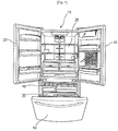
- FIG. 3 is a perspective view illustrating an opened state of refrigerating compartment doors and an opened state of a freezing compartment door in the refrigerator shown in FIG. 2 .
- FIG. 4 is a perspective view illustrating flow paths cf cold air in an ice making compartment and a cold air guide device in the refrigerator shown in FIG. 2 .
- FIG. 5 is a perspective view illustrating the inner side cf a part cf one refrigerating compartment door where the ice making compartment is arranged, in the refrigerator shown in FIG. 2 .
- the refrigerator according to the first embodiment not forming part of the present invention includes a refrigerator body 100, and an ice making compartment 500 in which ice is made.
- the inner space of the refrigerator body 100 is partitioned into a refrigerating compartment 200 and a freezing compartment 300.
- shelves and drawers cf various shapes are arranged in the refrigerating compartment 200, in order to efficiently receive various kinds of food.
- the flow cf cold air supplied to the refrigerating compartment 200 at one side of the refrigerating compartment 200 is influenced by the shelves and drawers such that convection of the cold air is limited or controlled.
- the cold air is supplied in different amounts to portions cf the refrigerating compartment 200 defined by the shelves and drawers, respectively, so that the portions cf the refrigerating compartment 200 have different temperature characteristics.
- the refrigerating compartment 200 is open at the front side thereof.
- the refrigerating compartment 200 includes a refrigerating compartment door unit 400 which selectively opens or closes the front side of the refrigerating compartment 200.
- the refrigerating compartment door unit 400 opens or closes the inner space cf the refrigerating compartment 200.
- the refrigerating compartment door unit 400 includes a pair cf hinged doors 410 and 420 hingably connected to the refrigerator body 100.
- the left one of the hinged doors 410 and 420 namely, the door 410
- the right one of the hinged doors 410 and 420 may be hingably connected, at the right end thereof, to the right corners cf the front side of the refrigerating compartment 200 by means of hinges, respectively.
- the left and right doors 410 and 420 are openable independently of each other.
- Shelves 411 and 421 may be installed at the refrigerating compartment door unit 400, in order to receive drink bottles and other food.
- the freezing compartment 300 is adapted to store fish, meat, or food required to be stored for a prolonged period of time, in a frozen state.
- Drawers and baskets (not shown) are arranged in the freezing compartment 300, in order to separately store a variety of food to be stored in a frozen state, depending on the size or state of the food.
- the temperature of the freezing compartment 300 is controlled by a heat exchanger 310 installed at the refrigerator body 100.
- the inner space of the freezing compartment 300 is maintained in a low-temperature state by cold air generated by the heat exchanger 310, in order to freeze the food stored in the freezing compartment 300.
- a refrigerant which passes through the heat exchanger 310, is evaporated as it absorbs heat from cold air supplied to the freezing compartment 300, thereby lowering the temperature of the cold air.
- the inner space cf the freezing compartment 300 is maintained at a temperature capable of storing food in a frozen state.
- the heat exchanger 310 is arranged at the rear side cf the freezing compartment 300, in particular, at the rear side of a storage box 330 arranged in the freezing compartment 300.
- the storage box 330 receives the above-described drawers and/or baskets, in order to store food.
- a fan (not shown) is arranged at one side of the heat exchanger 310, in order to forcibly circulate air in the freezing compartment 300.
- a freezing compartment door 320 is arranged at the open front side of the freezing compartment 300, in order to open or close the freezing compartment 300.
- the freezing compartment door 320 is hingably connected, at a lower end thereof, to a lower end of the front side of the storage box 330.
- the storage box 330 is coupled to the refrigerator body 100 such that the storage box 330 is slidable in forward and rearward directions.
- the storage box 330 is forwardly extendable or rearwardly retractable together with the freezing compartment door 320.
- a lower handle 321 may be attached to a front surface of the freezing compartment door 320, in order to open or close the freezing compartment door 320.
- a shelf 322, which can receive food, may be attached to a rear surface cf the freezing compartment door 320.
- the heat exchanger 310 is configured to perform temperature control for both the refrigerating compartment 200 and the freezing compartment 300.
- the refrigerating compartment 200 may be temperature-controlled by a separate heat exchanger (not shown).
- the refrigerating compartment 200 and freezing compartment 300 which have the above-described configurations, respectively, are partitioned by a barrier 210.
- the refrigerating compartment 200 is more frequently used than the freezing compartment 300. To this end, it is preferred that the refrigerating compartment 200 be arranged over the freezing compartment 300 so as to enable the user to easily take out the food stored in the refrigerating compartment 200 without bending his body.
- the barrier 210 is horizontally arranged in the refrigerator body 100 such that the barrier 210 defines the bottom of the refrigerating compartment 200, and the top of the freezing compartment 300.
- the ice making compartment 500 basically functions to make ice, and to store the ice. It is preferred that the ice making compartment 500 be arranged at an appropriate position in the refrigerator, in order to enable the user to easily take out ice made in the ice making compartment 500, irrespective of the size or capacity of the refrigerator, and the arrangement of the freezing compartment 300 and refrigerating compartment 200.
- the refrigerator include a cold air guide device for guiding cold air generated by the heat exchanger 310 to the ice making compartment 500.
- the refrigerator includes a cold air guide device for guiding a part of cold air generated by the heat exchanger 310, in order to enable the ice maker to be arranged at a most appropriate position, irrespective cf the size or capacity of the refrigerator, and the arrangement cf the freezing compartment 300 and refrigerating compartment 200.
- the refrigerating compartment 200 when the refrigerating compartment 200 is arranged over the freezing compartment 300, it is possible to more easily take out the food stored in the inner space cf the refrigerating compartment 200, in particular, a lower portion of the refrigerating compartment 200.
- the ice making compartment 500 be arranged in the refrigerating compartment 200, in order to enable the user to easily take out the ice stored in the ice making compartment 500.
- the ice making compartment 500 is provided at the refrigerating compartment door unit 400.
- a dispenser 430 is also provided at the refrigerating compartment door unit 400, in addition to the ice making compartment 500.
- the dispenser 430 functions to enable the user to take out water purified in the refrigerator and ice made in the ice making compartment 500 at the outside cf the refrigerator.
- Operating buttons 450 for control of the internal temperatures of the compartments in the refrigerator, and other functions, and a display unit 440 for displaying the operating state of the refrigerator are arranged on the front surface cf the refrigerator body 100.
- the ice making compartment 500 is arranged at the inner side cf the refrigerating door unit 400, in particular, at the inner side of the left door 410.
- the dispenser 430 is arranged to discharge the ice stored in the ice making compartment 500 at the front side of the left door 410.
- the ice making compartment 500 and dispenser 430 may be arranged at the right door 420.
- the dispenser 430 In order to enable the dispenser 430 to discharge the ice made in the ice making compartment 500 by gravity, it is preferred that the ice making compartment 500 be arranged over the dispenser 430.
- the ice making compartment 500 has a rear wall which is protruded from the left door 410 into the refrigerating chamber 200.
- the ice making compartment 500 includes an ice making chamber 510 in which an ice maker 511 adapted to make ice using cold air generated by the heat exchanger 310 is received, and an ice making compartment door 520 which opens or closes an opening formed at a rear side cf the ice making chamber 510.
- the ice making compartment 500 is defined by an inner case (not shown) coupled to the rear surface cf the left door 410. Accordingly, the inner space of the ice making compartment 500 is partitioned from the inner space of the refrigerating compartment 200.
- the ice maker 511 which makes ice using cold air generated by the heat exchanger 310, is arranged in the interior cf the ice making compartment 500, namely, the ice making chamber 510.
- a feeder 512 is also received in the ice making chamber 510.
- the feeder 512 is arranged beneath the ice maker 511, to store and feed ice made by the ice maker 511.
- the feeder 512 not only stores ice made by the ice maker 511, but also feeds the ice to the dispenser 430, in order to enable the user to take out the ice through the dispenser 430, if necessary.
- the cold air guide device functions to guide the cold air generated by the heat exchanger 310 to the ice making chamber 510 cf the ice making compartment 500.
- the cold air guide device includes a duct unit 600 which communicates with the ice making compartment 500.
- the duct unit 600 defines a flow path of the cold air generated by the heat exchanger 310.
- the refrigerator according to the first embodiment not forming part of the present invention further includes a cold air supply fan 630 which forces the cold air generated by the heat exchanger 310 to flow through the ice making compartment 500.
- a part of the cold air generated by the heat exchanger 310 is introduced into the ice making compartment 500 via the duct unit 600 in accordance with the driving of the cold air supply fan 630.
- the ice making compartment 500 may be configured to be selectively connected to the duct unit 600, as in this embodiment.
- the ice making compartment 500 and duct unit 600 are configured to be connected to each other only in a closed state of the left door 410.
- the ice making chamber 500 communicates with the duct unit 600.
- a first opening 601 is formed through an inner wall of the refrigerating compartment 200.
- the first opening 601 defines one end of the duct unit 600, in particular, an upper end of the duct unit 600.
- a second opening 501 which is selectively connected to the first opening 601, is formed at the refrigerating door unit 400, in particular, the left door 410.
- the second opening 501 When the second opening 501 is connected to the first opening 610, the second opening 501 communicates with the inner space cf the ice making compartment 500, in particular, the ice making chamber 510.
- the second opening 501 is connected to the first opening 601.
- the second opening 501 is disconnected from the first opening 601.
- the ice making compartment 500 may be configured to always communicate with the duct unit 600.
- the duct unit 600 may be directly connected, at one end thereof, to one side of the refrigerator door unit 400 where the ice making compartment 500 is defined, and may be connected, at the other end thereof, to one side of the freezing compartment 300.
- the duct unit 600 includes at least one duct, two ducts 610 and 620 in the illustrated case, arranged at one side wall cf the refrigerating compartment 200.
- the ice making compartment 500 is arranged at the left door 410, as in this embodiment, it is preferred that the ducts 610 and 620 be arranged at the left wall of the refrigerating compartment 200.
- the ducts 610 and 620 function to supply cold air generated by the heat exchanger 310 to the ice making compartment 500.
- these ducts are collectively referred to as an air supply duct 610.
- the air supply duct 610 is configured such that one end of the air supply duct 610, namely, the upper end cf the air supply duct 610, communicates with the ice making compartment 500, and the other end of the air supply duct 610, namely, the lower end cf the air supply duct 610, communicates with the freezing compartment 300.
- the air supply duct 610 guides a part of the cold air, supplied to the freezing compartment 300, to the ice making compartment 500.
- the other end of the air supply duct 610 may be open to one side of the heat exchanger 310 such that the air supply duct 610 directly sucks cold air from the heat exchanger 310, to guide the sucked cold air to the ice making compartment 500.
- the cold air introduced into the ice making compartment 500 absorbs heat from water in the ice making compartment 500.
- the cold air emerging from the ice making compartment 500 may be introduced into the interior of the refrigerating compartment 200. However, it is preferred that the cold air emerging from the ice making compartment 500 be returned to the freezing compartment 300, taking into consideration the temperature difference between the cold air in the refrigerating compartment 200 and the cold air in the ice making compartment 500.
- the duct unit 60 preferably further includes a duct 620 which is connected to the ice making compartment 500, to guide the cold air from the ice making compartment 500 to the freezing compartment 300.
- the duct 620 is referred to as a return duct.
- One end cf the return duct 620 namely, the upper end of the return duct 620, is connected to the ice making compartment 500, whereas the other end of the return duct 620, namely, the lower end cf the return duct 620, is connected to one side of the freezing compartment 300 such that the return duct 620 communicates with the inner space of the freezing compartment 300.
- the first opening 601 includes a duct-side air supply port 601a which allows the cold air emerging from the supply air duct 610 to be discharged into the ice making chamber 500.
- the second opening 501 includes a door-side inlet 501a which is formed through an inner wall cf the left door 410 such that the door-side inlet 501a is selectively connected to the duct-side air supply port 601a.
- the first opening 601 further includes a duct-side inlet 601b which receives the cold air emerging from the ice making compartment 500, to guide the received cold air to the freezing compartment 300.
- the second opening 501 further includes a door-side outlet 501b which is formed through the inner wall of the left door 410 such that the door-side outlet 501b is selectively connected to the duct-side inlet 601b.
- At least one of the ducts 610 and 620 is preferably arranged between outer and inner walls defining one side of the refrigerating compartment 200, namely, the left side cf the refrigerating compartment 200.
- the outer wall defines the left appearance cf the refrigerator body 100
- the inner wall defines the left inner wall cf the refrigerating compartment 200.
- the air supply duct 610 be arranged between the outer and inner walls, because the temperature of the cold air flowing through the air supply duct 610 is lower than the temperature of the cold air flowing through the return duct 620.
- both the air supply duct 610 and the return duct 620 be arranged between the outer and inner walls, as in this embodiment.
- the space between the walls of the refrigerating compartment 200, namely, the outer and inner walls of the refrigerating compartment 200 is filled with an insulating material such as foamed urethane, in order to prevent the internal temperature of the refrigerating compartment 200 from being varied by the cold air flowing through the duct unit 600, and to minimize an increase in the temperature of the cold air flowing through the ducts 610 and 620.
- an insulating material such as foamed urethane
- the air supply duct 610 is arranged at the left side of the refrigerating compartment 200 in the space between the outer and inner walls cf the refrigerating compartment 200, it is preferred that the first opening 601 be arranged at the left inner wall of the refrigerating compartment 200. In this case, it is also preferred that the second opening 501 be arranged at the inner case of the refrigerating compartment door unit 400.
- the duct-side air supply port 601a and duct-side inlet 601b may be formed at a front portion cf the left inner wall of the refrigerating compartment 200.
- One end of the air supply duct 610 namely, the outlet of the air supply duct 610, is connected to the duct-side air supply port 601a.
- One end of the return duct 620 namely, the inlet of the return duct 620, is connected to the duct-side inlet 601b.
- the door-side inlet 501a and door-side outlet 501b are formed at the inner case such that they correspond to the duct-side air supply port 601a and duct-side inlet 601b, respectively.
- the outlet of the air supply duct 610 may form the duct-side air supply port.
- the inlet of the return duct 620 may form the duct-side air supply port.
- the first opening 601 and second opening 501 are connected to each other.
- a part cf the cold air supplied to the freezing compartment 300 is supplied to the interior of the ice making compartment 500 via the air supply duct 610.
- the cold air used to make ice in the ice making compartment 500 is returned to the freezing compartment 300 via the return duct 620.
- cold air which is supplied to the freezing compartment 300 after being cooled by the heat exchanger 310, freezes food stored in the freezing compartment 300.
- a part of cold air generated by the heat exchanger 310 is forcibly fed to the ice making compartment 500 via the air supply duct 610 by the cold air supply fan 630.
- the cold air introduced into the ice making compartment 500 heat-exchanges with water supplied to the ice maker 540.
- making of ice is carried out in the ice making compartment 500.
- the cold air which has performed heat exchange, namely, has been used to make ice, is introduced into the return duct 620 through the duct-side inlet 601b connected to the door-side outlet 501b, and is then returned to the freezing compartment 300 via the return duct 620.
- the cold air introduced into the freezing compartment 300 is cooled as it heat-exchanges again with the heat exchanger 310.
- the resultant cold air is then supplied to the freezing compartment 300 or ice making compartment 500.
- Ice made in the ice making compartment 500 is stored in the feeder 512.
- the ice stored in the feeder 512 is subsequently externally discharged through the dispenser 420 in accordance with operation cf the user.
- FIGs. 6 to 9 a refrigerator according to a second embodiment disclosing the present invention will be described with reference to FIGs. 6 to 9 .
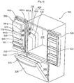
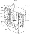
- FIG. 6 is a perspective view of the refrigerator according to the second embodiment disclosing the present invention, illustrating an opened state of refrigerating compartment doors and an opened state cf a freezing compartment door.
- FIG. 7 is a perspective view illustrating a cold air guide device and one door of the refrigerator according to the second embodiment disclosing the present invention.
- FIG. 8 is an exploded perspective view illustrating a sealing unit applied to the refrigerator shown in FIG. 7 .
- FIG. 9 is a sectional view illustrating the sealing unit applied to the refrigerator shown in FIG. 7 .
- the basic constituent elements of the refrigerator according to the second embodiment disclosing the present invention are identical to those cf the refrigerator according to the first embodiment not forming part cf the present invention.
- the constituent elements identical to those cf the first embodiment not forming part of the present invention will be designated by the same reference numerals as those used in the first embodiment not forming part of the present invention, respectively, and no additional description thereof will be given.
- the refrigerator according to the second embodiment disclosing the present invention includes sealing units 710 and 720 for preventing cold air from being leaked between the first opening 601 and the second opening 501.
- a handle 521 is provided at the ice making compartment door 520. Also, the ice making compartment door 520 is hingably mounted to one edge of an opening formed through the rear wall cf the ice making chamber 510.
- the opening/closing structure of the ice making compartment door 520 and handle 521 may be applied to the refrigerator according to the first embodiment not forming part of the present invention in the same manner as described above.
- the opening formed through the rear wall of the ice making chamber 510 is formed at an inner liner 530 which is coupled to the inner wall cf the left door 410.
- the ice making compartment door 520 is opened while being hingably moved.
- the sealing units 710 and 720 may be provided at one cf the first and second openings 601 and 501.
- sealing units 710 and 720 may be provided at the first and second openings 610 and 501, respectively.
- sealing units 710 and 720 will be described in more detail with reference to Figs. 8 and 9 . Since the sealing units 710 and 720 have the same structure, the following description will be given only in conjunction with one cf the sealing units 710 and 720, for example, the sealing unit 710.
- the sealing unit 710 is provided at the second opening 510 of the inner case 530, and functions to prevent cold air from being leaked through the first opening 601 and the second opening 501.
- the sealing unit 710 includes a gasket 711, and a gasket fixer for fixing the gasket 711 to the first opening 601 provided at the inner wall of the refrigerating compartment 200.
- the gasket 711 is in contact with the first opening 601.
- the gasket fixer includes a gasket supporter 713 which is coupled to the first opening 601, and a gasket holder 712 which fixes the gasket 711 to the gasket supporter 713.
- the gasket holder 712 is coupled to the gasket supporter 713, to fix the gasket 711 to the gasket supporter 713.
- the gasket supporter 713 is coupled to the edge cf the first opening 601, to fix the gasket 711 to the inner case 530.
- the gasket 711 includes a gasket body 711a, and a holder coupler 711d for coupling the gasket 711 to the gasket holder 712.
- a cold air hole 711b is provided at the gasket body 711a in order to allow the ice making compartment 500 and duct unit 600 to communicate with each other.
- the cold air hole 711b is formed through the gasket body 711a.
- the gasket body 711a is made up of a ring-shaped member such that the cold air hole 711b is defined at a central portion of the gasket body 711a.
- a reinforcing rib 711c be provided at the cold air hole 711b.
- the reinforcing rib 711c includes a first rib having an approximately cross shape, and an annular second rib which has an outer diameter smaller than an inner diameter cf the cold air hole 711b, and is formed integrally with the first rib.
- the holder coupler 711d forms a holder receiving groove 711 f for receiving the gasket holder 712. To form the holder receiving groove 711f the holder coupler 711d extends radially inwardly from the edge of the gasket body 711a, and then extends radially outwardly after being bent.
- the bent portion of the holder coupler 711d forms the holder receiving groove 711f for receiving the gasket holder 712, as shown in FIG. 9 .
- the gasket holder 712 includes a holder body 712a having an approximately ring shape, and at least one fixing member 712b which is coupled to the gasket supporter 713.
- the holder body 712a is fitted in the holder receiving groove 711f.
- the fixing member 712b includes a hook extending from the edge of the holder body 712a at one side of the holder body 712a such that the hook is integral with the holder body 712a.
- the hook extends toward the gasket supporter 713.
- the hook is coupled to the gasket supporter 713, thereby fixing the gasket 711 to the gasket supporter 713.
- portion cf the holder coupler 711d extending from the bent portion cf the holder coupler 711d outwardly from the gasket body 711a is interposed between the holder body 712a and the gasket supporter 713.
- a hook groove 711e through which the hook extends, is formed at the portion of the holder coupler 711d extending from the bent portion of the holder coupler 711d outwardly from the gasket body.
- the number of hook grooves 711e is identical to the number of hooks.
- four hooks 711e, which are spaced apart from one another by an angle of 90°, are formed at the holder coupler 711d.
- four hooks, which are spaced apart from one another by an angle of 90°, are formed at the holder body 712a.
- the gasket supporter 713 includes a supporter body 713a, and hook coupling holes 713c formed at the supporter body 713a such that the hook coupling holes 713c correspond to the hooks, respectively.
- the supporter body 713a has a recessed step on which the gasket holder 712 and gasket 711 are seated.
- a communicating hole 713b having a predetermined diameter is formed through the support body 713a inside the step.
- the communicating hole 713b communicates with the cold air hole 711b of the gasket 711.
- the hooks extend through the hook coupling holes 713c, respectively, and engage with the rear surface of the supporter body 713a.
- hook engaging grooves 713d are formed at the rear surface cf the supporter body 713a.
- the hook engaging grooves 713d receive respective ends cf the hooks.
- a support protrusion 712c is formed at each hook.
- the support protrusion 712c supports the edge of the associated hook engaging groove 713d at one side of the associated hook engaging groove 713d.
- Each hook is preferably made of an elastic material.
- the gasket 711 having the above-described structure be made of a flexible material.
- the gasket 711 may be made of a material having elasticity, such as rubber.
- the gasket supporter 713 is fixed to the left door 210.
- the gasket supporter 713 is fixed to the second opening 501 of the inner case 530, thereby supporting the gasket holder 420 such that the gasket holder 420 is fixedly maintained.
- sealing units 710 and 720 which have the above-described configuration, may also be provided at the first opening 601.
- the sealing units 710 and 720 are provided at at least one of the duct-side air supply port 601a, duct-side inlet 601b, door-side inlet 501a, and door-side outlet 501b.
- the sealing units 710 and 720 be provided at at least one of the duct-side air supply port 601a and door-side inlet 501a and at least one of the duct-side inlet 601b and door-side outlet 501b.
- the sealing units 710 and 720 may be provided at each of the duct-side air supply port 601a, duct-side inlet 601b, door-side inlet 501a, and door-side outlet 501b.
- cold air generated by the heat exchanger 310 is introduced into the air supply duct 610 of the duct unit after passing through the interior of the barrier 210.
- the duct unit 600 includes the return duct 620
- cold air discharged out of the ice making compartment 500 is introduced into the freezing compartment 300 after passing through the interior of the barrier 210.
- a grill pan 340 is arranged at the rear side of the freezing compartment 300, to form the rear wall of the freezing compartment 300.
- the grill pan 340 has a fan mounting portion 341 to which a cold air supply fan (not shown) is mounted.
- constituent elements of the refrigerant cycle such as a compressor and the heat exchanger 310 are installed at the rear side cf the grill fan 340.
- FIGs. 10 and 11 a refrigerator according to a third embodiment disclosing the present invention will be described with reference to FIGs. 10 and 11 .
- FIG. 10 is a front view illustrating an inner case included in a refrigerator door which is applied to the refrigerator according to the third embodiment disclosing the present invention.
- FIG. 11 is an exploded perspective view illustrating a door duct unit provided at the inner case shown in FIG. 10 , and a sealing unit provided at the door duct unit.
- the basic constituent elements of the refrigerator according to the third embodiment disclosing the present invention are identical to those of the refrigerator according to the first embodiment and/or second embodiment.
- the constituent elements identical to those of the first embodiment and/or second embodiment will be designated by the same reference numerals as those used in the first embodiment and/ or second embodiment, respectively, and no additional description thereof will be given.
- the ice making compartment 500 includes a door duct 540 which connects the interior of the ice making compartment 500 to the duct unit 600, as shown in FIGs. 10 and 11 .
- the door duct 540 is provided at the refrigerating compartment door unit 400, in particular, in the interior of the inner case 530 cf the left door 410.
- the top wall of the inner case 530 is rearwardly recessed to form the ice making chamber 510.
- the door duct 540 may be arranged inside the second opening 501 such that the door duct 540 communicates with the second opening 501.
- the door duct 540 may be exposed externally cf the inner case 530 at one side cf the door duct 540 such that the door duct 540 forms the second opening 501.
- the door duct 540 is received in a space defined between the second opening 501 and the ice making chamber 510, in a fixed state.
- the door duct 540 has a first duct portion 541 which communicates with the air supply duct 610, and a second duct portion 542 which communicates with the return duct 620.
- the inlet of the first duct portion 541 and the outlet cf the second duct portion 542 form the door-side inlet 501a and door-side outlet 501b, respectively. It is preferred that the above-described sealing unit 710 be provided at each of the inlet of the first duct portion 541 and the outlet of the second duct portion 542.
- the first duct portion 541 includes a body 541b centrally formed with a through hole 541a.
- the through hole 541a have an inlet which forms the door-side inlet 501a. It is also preferred that the body 541b have a step recessed to a predetermined depth to receive the sealing unit 710.
- the step has an edge having the same shape as the appearance of the gasket supporter 713 and has a depth approximately identical to the thickness of the gasket supporter 713 in order to prevent the sealing unit 701 from joggling after being fitted in the step.
- a plurality cf supporter mounting grooves 541c are formed at the step, in order to fix the gasket supporter 713 to the step of the first duct portion 541. Also, the above-described coupling protrusions (not shown) are formed at the gasket supporter 713. The coupling protrusions are engaged in the supporter mounting grooves 541c, respectively.
- the second duct portion 542 may have the same structure as that cf the first duct portion 541.
- the door duct 540 is made cf an insulating material in order to minimize thermal loss of cold air because the door duct 540 guides cold air introduced into or discharged out of the duct unit 600.
- the door duct 540 is made cf an insulating material such as expanded polystyrene (EPS) which is easily moldable, and has superior insulation properties.
- EPS expanded polystyrene
- cold air supplied from the heat exchanger 310 is introduced into the ice making chamber 510 via the air supply duct 610 and first duct portion 541 of the door duct 540.
- cold air discharged out cf the ice making chamber 510 is returned to the freezing compartment 300 via the second duct portion 542 of the door duct 540 and return duct 620.
- FIGs. 12 and 16 a refrigerator according to a fourth embodiment not forming part of the present invention will be described with reference to FIGs. 12 and 16 .
- FIG. 12 is a perspective view illustrating a cold air guide device and a refrigerator door which are applied to the refrigerator according to the fourth embodiment not forming part of the present invention.
- FIG. 13 is a perspective view illustrating a part cf a duct constituting the cold air guide device shown in FIG. 12 .
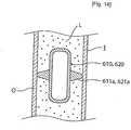
- FIG. 14 is a sectional view illustrating a state in which the duct shown in FIG. 13 is installed at one wall of the refrigerator.
- FIG. 15 is a perspective view illustrating a duct holder applied to the refrigerator according to the fourth embodiment not forming part of the present invention.
- FIG. 16 is a sectional view illustrating a state in which the duct is installed at one wall of the refrigerator by the duct holder shown in FIG. 15 .
- the basic constituent elements cf the refrigerator according to the fourth embodiment not forming part cf the present invention are identical to those of the refrigerator according to at least one cf the first through third embodiments.
- the constituent elements identical to those cf at least one cf the first through third embodiments will be designated by the same reference numerals as those used in at least one of the first through third embodiments, respectively, and no additional description thereof will be given.
- the refrigerator according to the fourth embodiment not forming part of the present invention includes a spacer which spaces ducts internally arranged at one side wall cf the refrigerator from the outer wall O and inner wall I forming the side wall of the refrigerator.
- the ducts include the above-described air supply duct 610 and return duct 620.
- the spacer supports the air supply duct 610 and/or return duct 620 to be spaced apart from the outer wall O and inner wall I.
- the spacer is provided to minimize thermal loss cf cold air flowing through the duct unit 600 and to easily fill a foaming liquid between the outer wall O and the inner wall I.
- the spacer be configured to uniformly space each of the ducts 610 and 620 from the outer wall O and inner wall I.
- the spacer includes at least one spacing rib protruded from the outer surface cf an associated one of the ducts 610 and 620.
- the spacing rib functions to arrange the associated duct, namely, the air supply duct 610 or return duct 629, at a desired correct position in one side wall of the refrigerating compartment 200.
- the spacer includes two spacing ribs 611a or 621a which are protruded from the outer surface cf the associated air supply duct 610 or return duct 620 in a symmetrical manner.
- spacing ribs 611a and spacing ribs 621a are provided at the air supply duct 610 and return duct 620, respectively.
- the spacing ribs 611a or 621a extend in opposite directions from the outer surface cf the associated duct 610 or 620, respectively.
- the air supply duct 610 and/or return duct 620 is centrally arranged between the outer wall O and the inner wall I.
- the spacing ribs 611a and 621a preferably have a shape having a small cross-sectional area, in order to minimize the area of the spacing ribs 611a and 621a contacting the outer wall O and inner wall I. Accordingly, it is possible to minimize thermal loss caused by the spacing ribs.
- the foaming liquid L filling the space between the outer wall O and inner wall I can smoothly flow.
- the foaming liquid L can sufficiently fill the space between the inner wall I and the outer wall O.
- the air supply duct 610 includes at least one main duct 611 which guides cold air to flow rectilinearly, and a connecting duct 612 which varies the flow direction of cold air flowing through the air supply duct 610.
- the connecting duct 612 may be connected to one end cf the main duct 611. Where the air supply duct 610 includes, for example, two main ducts 611, the connecting duct 612 may be connected between the facing ends cf the main ducts 611.
- the return duct 620 includes, similarly to the air supply duct 610, at least one main duct 621 which guides cold air to flow rectilinearly, and a connecting duct 622 which varies the flow direction cf cold air flowing through the return duct 620.
- the connecting duct 622 may be connected to one end cf the main duct 621.
- the return duct 620 includes, for example, two main ducts 621
- the connecting duct 622 may be connected between the facing ends cf the main ducts 621.
- Each cf the main ducts 611 and 621 has an approximately rectilinear shape.
- Each of the connecting ducts 612 and 622 has a curved shape to guide a flow of cold air.
- the connecting duct 612 or 622 may form one end cf the associated air supply duct 610 or return duct 620. Where the connecting duct 612 or 622 is connected between the adjacent main ducts 611 or 621, it varies the flow direction cf cold air.
- the spacing ribs 611a and 621a are provided at the outer surfaces of the associated connecting ducts 612 and 622, respectively.
- the spacing ribs 611a and 621a may be provided at the outer surfaces cf the associated main ducts 611 and 621, respectively.
- the refrigerator according to the fourth embodiment not forming part cf the present invention may further include a duct holder 800 which functions to fix the ducts 610 and 620 to one side wall of the refrigerating compartment 200.
- At least one cf the air supply duct 610 and return duct 620 is coupled to the duct holder 800, and is fixed to one side wall of the refrigerating compartment 200 by the duct holder 800.
- the duct holder 800 includes duct receivers 810 and 820 which receive the ducts 610 and 620 in a fixed state, respectively.
- the duct holder 800 simultaneously fixes the air supply duct 610 and return duct 620.
- the duct holder 800 include a pair of duct receivers, namely, duct receivers 810 and 820, which are connected to each other such that they are integral.
- the duct receiver 810 which receives the air supply duct 610
- the duct receiver 820 which receives the return duct 620
- a second duct receiver is also referred to as a second duct receiver
- the duct receivers 810 and 820 have duct receiving holes 811 and 812 through which the ducts 610 and 620 extend, respectively.
- the duct receivers 810 and 820 are connected to each other by a connecting rib 830.
- the shapes cf the duct receiving holes 811 and 821 correspond to the outer cross-sectional shapes cf the air supply duct 610 and return duct 620, respectively. Accordingly, the air supply duct 610 and return duct 620 are fixed as they are fitted in the duct receiving hole 811 of the first duct receiver 810 and the duct receiving hole 821 cf the second duct receiver 820, respectively.
- the duct holder 800 preferably includes at least one spacing protrusion 840 outwardly protruded from the outer surface cf each cf the duct receivers 810 and 820.
- the spacing protrusion 840 has the same function as those cf the above-described spacing ribs 611a and 621a. Accordingly, the duct unit 600 may include the spacing protrusions 840 or the spacing ribs 611a and 621a alone.
- spacing protrusions 840 and the spacing ribs 611a and 621a are protruded from respective outer surfaces of the duct receivers 810 and 820, whereas the spacing ribs 611a and 621a are protruded from respective outer surfaces of the ducts 610 and 620.
- the spacing protrusions 840 formed at each cf the duct receivers 810 and 820 are arranged at opposite sides of the associated duct receiver 810 or 820. Accordingly, the spacing protrusions 840 maintain the air supply duct 610 and return duct 620 at a central position between the outer wall O and the inner wall I.
- the foaming liquid L filling the space between the inner wall I and the outer wall O can smoothly flow. Accordingly, the foaming liquid L can sufficiently fill the space between the inner wall I and the outer wall O.
- FIG. 17 is a perspective view illustrating a first heater which is applied to the refrigerator according to the fifth embodiment not forming part of the present invention, and is installed in a refrigerating compartment wall.
- the basic constituent elements of the refrigerator according to the fifth embodiment not forming part of the present invention are identical to those cf the refrigerator according to at least one of the first through fourth embodiments.
- the constituent elements identical to those of at least one of the first through fourth embodiments will be designated by the same reference numerals as those used in at least one of the first through fourth embodiments, respectively, and no additional description thereof will be given.
- the refrigerator according to the fifth embodiment not forming part of the present invention includes a first heater 851 which prevents a frosting phenomenon from occurring in the refrigerating compartment 200 due to cold air flowing through the ducts 610 and 620.
- At least one of the ducts 610 and 620 is arranged in one side wall of the refrigerating compartment 200.
- the first heater 851 is arranged on one side wall cf the refrigerating compartment 200.
- the ducts 610 and 620 are arranged between the outer wall O and inner wall I of the refrigerating compartment 200.
- the first heater 851 is arranged on the inner wall I of the refrigerating compartment 200.
- the first heater 851 is installed on the inner wall I cf the refrigerating compartment 200, to increase the temperature of the inner wall I cf the refrigerating compartment 200.
- the first heater 851 is preferably arranged on one surface of the inner wall I of the refrigerating compartment 200 contacting the filled foaming liquid L such that the first heater 851 is not outwardly exposed.
- the first heater 851 is arranged adjacent to the first opening 601.
- Cold air is introduced into the duct unit 600 through the duct-side air supply port 601a, and is discharged out of the duct unit 600 through the duct-side inlet 601b. If there is no heater arranged near the duct-side air supply port 601a and duct-side inlet 601b, such as the first heater 851, a decrease in temperature occurs around the duct-side air supply port 601a and duct-side inlet 601b due to the influence of the cold air flowing through the duct unit 600. For this reason, it is preferred that the first heater 851 be arranged adjacent to the first opening 601.
- the first heater 851 heats the inner wall of the refrigerating compartment 200 such that the temperature of the inner wall of the refrigerating compartment 200 is similar to the internal temperature of the refrigerating compartment 200.
- the first heater 851 be arranged around each of the duct-side air supply port 601a and duct-side inlet 601b.
- the first heater 851 includes a heating wire having a plurality of bent portions. The heating wire generates heat when external electric power is applied to the wire.
- the refrigerator may further include a temperature sensor which measures the wall temperature of the refrigerating compartment 200, and a power controller which selectively turns on or off the heater 130, based on the value measured by the temperature sensor.
- the first heater 851 having the above-described configuration, it is possible to prevent a frosting phenomenon from occurring at the inner surface of the refrigerating compartment 200 due to the cold air flowing through the duct-side air supply port 601a and duct-side inlet 601b.
- FIGs. 18 to 21 a refrigerator according to a sixth embodiment not forming part of the present invention will be described with reference to FIGs. 18 to 21 .
- the basic constituent elements cf the refrigerator according to the sixth embodiment not forming part cf the present invention are identical to those cf the refrigerator according to at least one cf the first through fifth embodiments.
- the constituent elements identical to those of at least one of the first through fifth embodiments will be designated by the same reference numerals as those used in at least one of the first through fifth embodiments, respectively, and no additional description thereof will be given.
- FIG. 18 is a perspective view of the refrigerator according to the sixth embodiment not forming part of the present invention, illustrating opened states of the refrigerating compartment doors and freezing compartment door.
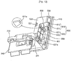
- FIG. 19 is a perspective view illustrating a cold air guide arranged at the barrier of the refrigerator shown in FIG. 18 .
- FIG. 20 is a perspective view illustrating a barrier cover which opens or closes the cold air guide shown in FIG. 19 .
- FIG. 21 is a perspective view illustrating a state in which the cold air guide is closed by the barrier cover shown in FIG. 20 .
- the refrigerator according to the sixth embodiment not forming part of the present invention includes a cold air guide 900 which is arranged in the barrier 210 partitioning the refrigerating compartment 200 and freezing compartment 300.
- the cold air guide 900 is configured to connect the duct unit 600 and freezing compartment 300.
- the cold air guide 900 includes an air supply passage 910 which guides cold air generated by the heat exchanger 310 to the air supply duct 610.
- the cold air guide 900 further includes a return passage 920.
- a partition wall 930 be arranged between the air supply passage 910 and the return passage 920.
- the return passage 920 guides cold air, which is guided through the duct unit, in particular, the return duct 620, after emerging from the ice making compartment 500, to the freezing compartment 300.
- the air supply passage 910 includes an air supply hole 911 which extends vertically, and an air supply guide 912 which guides cold air from the air supply hole 911 to the air supply duct 610.
- the return passage 920 includes a return hole 921 which extends vertically, and a return guide 922 which guides cold air from the return duct 620 to the return hole 921.
- the barrier 210 includes a cover 211 which opens or closes the cold air guide 900.
- the cover 211 is separably coupled to the cold air guide 900.
- the cover 211 includes an air supply cover 211a for opening or closing the air supply passage 910, and a return cover 211b for opening or closing the return passage 920.
- the air supply cover 211a and return cover 211b are integrally formed.
- the cover 211 also includes a partition groove 211c formed between the air supply cover 211a and the return cover 211b, to provide a sealing effect between the air supply passage 910 and the return passage 920.
- the cover 211 having the above-described configuration is detachably attached to the top of the cold air guide 900.
- a second heater 861 be provided at the barrier 210, in order to prevent a frosting phenomenon from occurring in the interior of the refrigerating compartment 200.
- the second heater 861 is arranged at one surface cf the barrier 210 facing the interior cf the refrigerating compartment 200, namely, the top surface of the barrier 210. That is, the second heater 861 is arranged at the bottom of the refrigerating compartment 200. Electric wires 861a are connected to the second heater 861, to supply electric power to the second heater 861.
- the barrier 210 includes the cover 211 for opening or closing the cold air guide 900, as in this embodiment, it is more preferable for the second heater 861 to be arranged at the top surface of the cover 211.
- the second heater 861 is configured to operate selectively in accordance with a predetermined condition.
- the second heater 861 is automatically turned on or off in accordance with the temperature at the bottom of the refrigerating compartment 200. That is, when the temperature value measured by a temperature sensor (not shown), which measures the temperature at the bottom of the refrigerating compartment 200, is lower than a predetermined lower limit, the second heater 861 is turned on by a power supply controller (not shown). On the other hand, when the temperature value measured by the temperature sensor is higher than a predetermined upper limit, the second heater 861 is turned off by the power supply controller.
- the basic constituent elements cf the refrigerator according to the seventh embodiment disclosing the present invention are identical to those cf the refrigerator according to at least one cf the first through sixth embodiments .
- the constituent elements identical to those of at least one of the first through sixth embodiments will be designated by the same reference numerals as those used in at least one of the first through sixth embodiments, respectively, and no additional description there of will be given.
- FIG. 22 is a perspective view of an ice making compartment applied to the refrigerator according to the seventh embodiment disclosing the present invention, taken at the rear side.
- the ice making compartment door 520 in the refrigerator according to the seventh embodiment disclosing the present invention is hingably connected to one side of the opening of the freezing compartment 510 by hinges 522.
- the ice making compartment door 520 is hingably openable about the hinges 522.
- hinges 522 be arranged on upper and lower corners of the ice making compartment door 520 at one edge of the ice making compartment door 520.
- the refrigerator according to the seventh embodiment disclosing the present invention further includes a hinge cover 523 which covers each hinge 522.
- a cover mount 524 is provided at the associated corner of the ice making compartment door 520.
- the hinge cover 523 has a size and shape corresponding to those of the associated cover mount 524.
- the hinge cover 523 prevents an accident in that a portion of the body of the user is caught in the hinge 522 through his carelessness, and makes the appearance of the ice making compartment beautiful.
Description
- The present invention relates to a refrigerator, and more particularly, to a refrigerator which includes an ice making compartment for making ice.
- Generally, refrigerators are used to store food in a low-temperature and fresh state for a prolonged period of time. Such a refrigerator stores in a frozen or refrigerated state in accordance with the state or kind of the food.
- In order to store food in a low-temperature state, the refrigerator includes a refrigerant system which repeatedly performs a refrigerant cycle of compression-condensation -expansion-evaporation.
- Hereinafter, a conventional refrigerator will be described with reference to
FIG. 1 . - Referring to
FIG. 1 , the conventional refrigerator includes arefrigerator body 10 which includes a refrigeratingcompartment 20 for storing food in a refrigerated state, and afreezing compartment 30 for storing food in a frozen state. - The refrigerating
compartment 20 andfreezing compartment 30 are partitioned such that they have independent spaces, respectively. Each of the refrigeratingcompartment 20 andfreezing compartment 30 is provided with an opening at the front side thereof. - The opening cf the refrigerating
compartment 20 is opened or closed by refrigeratingcompartment doors 22. The opening cf thefreezing compartment 30 is opened or closed by afreezing compartment door 32. - Generally, the refrigerating
compartment 20 is more frequently used than thefreezing compartment 30. To this end, the refrigeratingcompartment 20 is arranged over thefreezing compartment 30 so as to enable the user to easily take out the food stored in the refrigeratingcompartment 20 without bending his body. - Drawers, baskets, and shelves for receiving food cf various sizes and states are provided in the interior of the refrigerating
compartment 20 and at the refrigeratingcompartment doors 22. - The
freezing compartment door 32 is slidable in forward and rearward directions to open or close thefreezing compartment 30. A lower door handle is attached to the front surface cf thefreezing compartment door 32 at the upper portion of thefreezing compartment door 32, to enable the user to slide thefreezing compartment door 32 while grasping the lower door handle. - An
ice maker 40 is arranged in thefreezing compartment 30, in order to make ice using cold air generated by a heat exchanger and supplied to thefreezing compartment 30. - However, the conventional refrigerator having the above-mentioned configuration has various problems.
- First, there is a problem in that the
ice maker 40, which makes ice, is arranged in the interior of thefreezing compartment 30, and thefreezing compartment 30 is arranged beneath the refrigeratingcompartment 20 in the conventional refrigerator having the above-mentioned configuration. That is, it is inconvenient for the user to take ice out of theice maker 40 because the user must operate theice maker 40 after opening thefreezing compartment door 32 while bending his body. - The above-mentioned problem may be solved by arranging the
freezing compartment 30 over the refrigeratingcompartment 20. In this case, however, it is difficult for a short man or a child to take ice out of theice maker 40 arranged in the interior of thefreezing compartment 30, after opening thefreezing compartment 30, in the case in which the refrigerator has a large size. - Meanwhile, the
ice maker 40 may be installed at an appropriate position outside thefreezing compartment 30, separately from thefreezing compartment 30. In this case, however, there are various problems, for example, an increase in the manufacturing costs of the refrigerator, an increase in the volume of the refrigerator, and a difficultly in the manufacture of the refrigerator, because an ice-making heat exchanger must be installed in the ice making compartment. - For the above-mentioned reasons, it is required to develop a refrigerator which enables the user to easily take ice out of an ice maker without causing a variation in the capacity of the refrigerator or a limitation on the position of a freezing compartment.
-
EP 1 684 036 A2 describes an ice and water dispenser for a bottom freezer refrigerator positioned on a refrigerator compartment door. The ice maker and ice cube storage bin can have below 0°C air provided to maintain the ice maker and ice cube storage bin below 0°C. Supply and return ducts can convey below 0°C air to the ice maker and ice cube storage bin. The supply and return ducts can lead from the bottom freezer compartment or from an evaporator compartment. The ice maker and ice cube storage bin can be located in insulated sub-compartment to allow normal refrigerator compartment temperatures to be maintained in the above freezing refrigerator compartment. -
EP 1 517 102 A2 describes a refrigerator with an icemaker including a cabinet having a dividing wall for compartmentalization of a freezing chamber and a refrigerating chamber, a case provided to a door on the refrigerating chamber, having a cavity therein, a first duct for supplying cold air from a neighborhood of an evaporator in the freezing chamber to the cavity, the icemaker in the cavity for producing ice, an ice container in the cavity for storing the ice. and a dispenser in the door in communication with the cavity, thereby having ice supplied to a user at an outside of the refrigerator through a dispenser provided to the door. -
US 6735959 B1 discloses a refrigerator according to the preamble of claim 1. - The object is solved by the features of the independent claim.
- An object of the present invention devised to solve the above-mentioned problems lies in providing a refrigerator which enables the user to easily take ice out of an ice maker without causing a variation in the capacity of the refrigerator or a limitation on the position of a freezing compartment.
- In accordance with the present invention, this object can be accomplished by providing a refrigerator as disclosed in claim 1.
- According to the invention the refrigerating compartment is arranged over the freezing compartment.
- According to the invention the cold air guiding device includes a duct unit which communicates with the ice making compartment.
- According to the invention the ice making compartment is provided at a refrigerating compartment door unit which opens or closes an inner space cf the refrigerator. The duct unit includes a first opening which is provided at an inner wall cf the refrigerating compartment, and forms one end cf the duct unit connected to one side cf the refrigerating compartment door unit. The refrigerating compartment door unit includes a second opening which is connected to the first opening, to connect the duct unit to an inner space cf the ice making compartment.
- The refrigerator further comprises a sealing unit which is provided at at least one cf the first and second openings, to prevent air from being leaked between the first and second openings.
- The sealing unit includes a gasket, and a gasket fixer which fixes the gasket to at least one of the first and second openings.
- The gasket fixer may include a gasket supporter which is coupled to at least one cf the first and second openings, and a gasket holder which fixes the gasket to the gasket supporter.
- The ice making compartment may include a door duct unit which is provided at a refrigerating door unit for opening or closing an inner space of the refrigerating compartment, to connect the duct unit to an inner space of the freezing compartment.
- The ice making compartment may includes an ice making chamber which receives an ice maker for making ice using the cold air generated by the heat exchanger, and an ice making compartment door which opens or closes an opening formed at a rear side of the ice making chamber.
- The ice making compartment door may be hingably movable by a hinge mounted to one side cf the ice making chamber. The ice making compartment door may include a hinge cover which covers the hinge.
- The refrigerator according to the present invention has various effects as follows.
- First, since the refrigerator according to the present invention includes the cold air guiding device for guiding the cold air generated by the heat exchanger, which controls the temperature cf the freezing compartment, to the ice making compartment, it is possible to appropriately select the position of the ice making compartment irrespective of the structure or capacity of the refrigerator. Accordingly, it is possible to achieve an improvement in the freedom cf design cf the refrigerator, and a reduction in the manufacturing costs cf the refrigerator, and to maximize the inner space of the refrigerating compartment.
- Second, in the refrigerator according to the present invention, it is possible to conveniently use the refrigerating compartment, and to easily take ice out cf the ice making compartment because the freezing compartment is arranged beneath the refrigerating compartment.
- Third, since the refrigerator according to the present invention includes the hinge cover, which covers the hinge for hingably opening or closing the ice making compartment door, it is possible to prevent an accident in that a portion cf the body cf the user is caught in the hinge through his carelessness, and to make the appearance cf the ice making compartment beautiful.
- The accompanying drawings, which are included to provide a further understanding of the illustrate embodiments and together with the description serve to explain the principle of the invention.
- In the drawings:
-
FIG. 1 is a perspective view of a conventional refrigerator, illustrating an opened state cf refrigerating compartment doors and an opened state of a freezing compartment door; -
FIG. 2 is a front view illustrating a refrigerator according to a first embodiment not forming part of the present invention; -
FIG. 3 is a perspective view illustrating an opened state cf refrigerating compartment doors and an opened state of a freezing compartment door in the refrigerator shown inFIG. 2 ; -
FIG. 4 is a perspective view illustrating flow paths of cold air in an ice making compartment and a cold air guide device in the refrigerator shown inFIG. 2 ; -
FIG. 5 is a perspective view illustrating the inner side cf a part cf one refrigerating compartment door where the ice making compartment is arranged, in the refrigerator shown inFIG. 2 ; -
FIG. 6 is a perspective view cf a refrigerator according to a second embodiment disclosing the present invention, illustrating an opened state cf refrigerating compartment doors and an opened state of a freezing compartment door; -
FIG. 7 is a perspective view illustrating a cold air guide device and one door of the refrigerator according to the second embodiment of the present invention; -
FIG. 8 is an exploded perspective view illustrating a sealing unit applied to the refrigerator shown inFIG. 7 ; -
FIG. 9 is a sectional view illustrating the sealing unit applied to the refrigerator shown inFIG. 7 ; -
FIG. 10 is a front view illustrating an inner case included in a refrigerator door which is applied to a refrigerator according to a third embodiment disclosing the present invention; -
FIG. 11 is an exploded perspective view illustrating a door duct unit provided at the inner case shown inFIG. 10 , and a sealing unit provided at the door duct unit; -
FIG. 12 is a perspective view illustrating a cold air guide device and a refrigerator door which are applied to a refrigerator according to a fourth embodiment not forming part of the present invention; -
FIG. 13 is a perspective view illustrating a part of a duct constituting the cold air guide device shown inFIG. 12 ; -
FIG. 14 is a sectional view illustrating a state in which the duct shown inFIG. 13 is installed at one wall cf the refrigerator; -
FIG. 15 is a perspective view illustrating a duct holder applied to the refrigerator according to the fourth embodiment not forming part of the present invention; -
FIG. 16 is a sectional view illustrating a state in which the duct is installed at one wall cf the refrigerator by the duct holder shown inFIG. 15 ; -
FIG. 17 is a perspective view illustrating a first heater which is applied to a refrigerator according to a fifth embodiment not forming part of the present invention, and is installed in a refrigerating compartment wall; -
FIG. 18 is a perspective view of a refrigerator according to a sixth embodiment not forming part of the present invention, illustrating opened states of the refrigerating compartment doors and freezing compartment door; -
FIG. 19 is a perspective view illustrating a cold air guide arranged at the barrier of the refrigerator shown inFIG. 18 ; -
FIG. 20 is a perspective view illustrating a barrier cover which opens or closes the cold air guide shown inFIG. 19 ; -
FIG. 21 is a perspective view illustrating a state in which the cold air guide is closed by the barrier cover shown inFIG. 20 ; and -
FIG. 22 is a perspective view of an ice making compartment applied to a refrigerator according to a seventh embodiment disclosing the present invention, taken at the rear side. - Reference will now be made in detail to the preferred embodiments, examples of which are illustrated in the accompanying drawings. In the following description, the same title and same reference numeral will be given for the same configuration, and no additional description will be given thereof.
-
FIG. 2 is a front view illustrating a refrigerator according to a first embodiment not forming part of the present invention.FIG. 3 is a perspective view illustrating an opened state of refrigerating compartment doors and an opened state of a freezing compartment door in the refrigerator shown inFIG. 2 .FIG. 4 is a perspective view illustrating flow paths cf cold air in an ice making compartment and a cold air guide device in the refrigerator shown inFIG. 2 .FIG. 5 is a perspective view illustrating the inner side cf a part cf one refrigerating compartment door where the ice making compartment is arranged, in the refrigerator shown inFIG. 2 . - Referring to
FIGs. 2 to 5 , the refrigerator according to the first embodiment not forming part of the present invention includes arefrigerator body 100, and anice making compartment 500 in which ice is made. - The inner space of the
refrigerator body 100 is partitioned into arefrigerating compartment 200 and a freezingcompartment 300. - Although not shown, shelves and drawers cf various shapes are arranged in the
refrigerating compartment 200, in order to efficiently receive various kinds of food. - The flow cf cold air supplied to the
refrigerating compartment 200 at one side of therefrigerating compartment 200 is influenced by the shelves and drawers such that convection of the cold air is limited or controlled. As a result, the cold air is supplied in different amounts to portions cf therefrigerating compartment 200 defined by the shelves and drawers, respectively, so that the portions cf therefrigerating compartment 200 have different temperature characteristics. Thus, it is possible to store food in an appropriate portion cf therefrigerating compartment 200, depending on the storage condition of the food. - Meanwhile, the
refrigerating compartment 200 is open at the front side thereof. Therefrigerating compartment 200 includes a refrigeratingcompartment door unit 400 which selectively opens or closes the front side of therefrigerating compartment 200. Thus, the refrigeratingcompartment door unit 400 opens or closes the inner space cf therefrigerating compartment 200. - The refrigerating
compartment door unit 400 includes a pair cf hingeddoors refrigerator body 100. - The left one of the hinged
doors door 410, may be hingably connected, at the left end thereof, to the left corners cf the front side cf therefrigerating compartment 200 by means of hinges, respectively. The right one of the hingeddoors door 420, may be hingably connected, at the right end thereof, to the right corners cf the front side of therefrigerating compartment 200 by means of hinges, respectively. Thus, the left andright doors -
Shelves compartment door unit 400, in order to receive drink bottles and other food. - The freezing
compartment 300 is adapted to store fish, meat, or food required to be stored for a prolonged period of time, in a frozen state. Drawers and baskets (not shown) are arranged in the freezingcompartment 300, in order to separately store a variety of food to be stored in a frozen state, depending on the size or state of the food. - The temperature of the freezing
compartment 300 is controlled by aheat exchanger 310 installed at therefrigerator body 100. In detail, the inner space of the freezingcompartment 300 is maintained in a low-temperature state by cold air generated by theheat exchanger 310, in order to freeze the food stored in the freezingcompartment 300. - In other words, a refrigerant, which passes through the
heat exchanger 310, is evaporated as it absorbs heat from cold air supplied to the freezingcompartment 300, thereby lowering the temperature of the cold air. Thus, the inner space cf the freezingcompartment 300 is maintained at a temperature capable of storing food in a frozen state. - The
heat exchanger 310 is arranged at the rear side cf the freezingcompartment 300, in particular, at the rear side of astorage box 330 arranged in the freezingcompartment 300. Here, thestorage box 330 receives the above-described drawers and/or baskets, in order to store food. - Preferably, a fan (not shown) is arranged at one side of the
heat exchanger 310, in order to forcibly circulate air in the freezingcompartment 300. - A freezing
compartment door 320 is arranged at the open front side of the freezingcompartment 300, in order to open or close the freezingcompartment 300. The freezingcompartment door 320 is hingably connected, at a lower end thereof, to a lower end of the front side of thestorage box 330. Thestorage box 330 is coupled to therefrigerator body 100 such that thestorage box 330 is slidable in forward and rearward directions. Thestorage box 330 is forwardly extendable or rearwardly retractable together with the freezingcompartment door 320. - A
lower handle 321 may be attached to a front surface of the freezingcompartment door 320, in order to open or close the freezingcompartment door 320. Ashelf 322, which can receive food, may be attached to a rear surface cf the freezingcompartment door 320. - Meanwhile, in this embodiment, the
heat exchanger 310 is configured to perform temperature control for both therefrigerating compartment 200 and the freezingcompartment 300. Of course, therefrigerating compartment 200 may be temperature-controlled by a separate heat exchanger (not shown). - The
refrigerating compartment 200 and freezingcompartment 300, which have the above-described configurations, respectively, are partitioned by abarrier 210. - Generally, the
refrigerating compartment 200 is more frequently used than the freezingcompartment 300. To this end, it is preferred that therefrigerating compartment 200 be arranged over the freezingcompartment 300 so as to enable the user to easily take out the food stored in therefrigerating compartment 200 without bending his body. - Accordingly, the
barrier 210 is horizontally arranged in therefrigerator body 100 such that thebarrier 210 defines the bottom of therefrigerating compartment 200, and the top of the freezingcompartment 300. - Meanwhile, the
ice making compartment 500 basically functions to make ice, and to store the ice. It is preferred that theice making compartment 500 be arranged at an appropriate position in the refrigerator, in order to enable the user to easily take out ice made in theice making compartment 500, irrespective of the size or capacity of the refrigerator, and the arrangement of the freezingcompartment 300 and refrigeratingcompartment 200. - In conventional cases in which there is a limitation on the arrangement of an ice making compartment because the ice making compartment must be arranged in the freezing compartment, there is a difficulty in arranging the ice making compartment at an appropriate position in a refrigerator.
- Therefore, in order to not only make ice using the above-described heat exchanger without use cf a separate ice-making heat exchanger, but also to enable the ice maker to be arranged at an appropriate position enabling the user to most easily take out ice made by the ice maker, it is preferred that the refrigerator include a cold air guide device for guiding cold air generated by the
heat exchanger 310 to theice making compartment 500. - In other words, there is a feature in that the refrigerator includes a cold air guide device for guiding a part of cold air generated by the
heat exchanger 310, in order to enable the ice maker to be arranged at a most appropriate position, irrespective cf the size or capacity of the refrigerator, and the arrangement cf the freezingcompartment 300 and refrigeratingcompartment 200. - This is more effective when the freezing
compartment 300 is arranged beneath therefrigerating compartment 200. - In other words, when the
refrigerating compartment 200 is arranged over the freezingcompartment 300, it is possible to more easily take out the food stored in the inner space cf therefrigerating compartment 200, in particular, a lower portion of therefrigerating compartment 200. - Also, it is preferred that the
ice making compartment 500 be arranged in therefrigerating compartment 200, in order to enable the user to easily take out the ice stored in theice making compartment 500. In the illustrated case, theice making compartment 500 is provided at the refrigeratingcompartment door unit 400. - Referring to
FIGs. 2 to 5 , adispenser 430 is also provided at the refrigeratingcompartment door unit 400, in addition to theice making compartment 500. Thedispenser 430 functions to enable the user to take out water purified in the refrigerator and ice made in theice making compartment 500 at the outside cf the refrigerator.Operating buttons 450 for control of the internal temperatures of the compartments in the refrigerator, and other functions, and adisplay unit 440 for displaying the operating state of the refrigerator are arranged on the front surface cf therefrigerator body 100. - In accordance with this embodiment, the
ice making compartment 500 is arranged at the inner side cf the refrigeratingdoor unit 400, in particular, at the inner side of theleft door 410. Thedispenser 430 is arranged to discharge the ice stored in theice making compartment 500 at the front side of theleft door 410. Of course, theice making compartment 500 anddispenser 430 may be arranged at theright door 420. - In order to enable the
dispenser 430 to discharge the ice made in theice making compartment 500 by gravity, it is preferred that theice making compartment 500 be arranged over thedispenser 430. - The
ice making compartment 500 has a rear wall which is protruded from theleft door 410 into the refrigeratingchamber 200. - The
ice making compartment 500 includes anice making chamber 510 in which anice maker 511 adapted to make ice using cold air generated by theheat exchanger 310 is received, and an icemaking compartment door 520 which opens or closes an opening formed at a rear side cf theice making chamber 510. - The
ice making compartment 500 is defined by an inner case (not shown) coupled to the rear surface cf theleft door 410. Accordingly, the inner space of theice making compartment 500 is partitioned from the inner space of therefrigerating compartment 200. - The
ice maker 511, which makes ice using cold air generated by theheat exchanger 310, is arranged in the interior cf theice making compartment 500, namely, theice making chamber 510. Afeeder 512 is also received in theice making chamber 510. Thefeeder 512 is arranged beneath theice maker 511, to store and feed ice made by theice maker 511. - The
feeder 512 not only stores ice made by theice maker 511, but also feeds the ice to thedispenser 430, in order to enable the user to take out the ice through thedispenser 430, if necessary. - Meanwhile, the cold air guide device functions to guide the cold air generated by the
heat exchanger 310 to theice making chamber 510 cf theice making compartment 500. - Referring to
FIGs. 3 and4 , the cold air guide device includes aduct unit 600 which communicates with theice making compartment 500. - In detail, the
duct unit 600 defines a flow path of the cold air generated by theheat exchanger 310. Preferably, the refrigerator according to the first embodiment not forming part of the present invention further includes a coldair supply fan 630 which forces the cold air generated by theheat exchanger 310 to flow through theice making compartment 500. - Accordingly, a part of the cold air generated by the
heat exchanger 310 is introduced into theice making compartment 500 via theduct unit 600 in accordance with the driving of the coldair supply fan 630. - The
ice making compartment 500 may be configured to be selectively connected to theduct unit 600, as in this embodiment. - In detail, the
ice making compartment 500 andduct unit 600 are configured to be connected to each other only in a closed state of theleft door 410. - In other words, when the
left door 410 is closed, theice making chamber 500 communicates with theduct unit 600. - For this configuration, a
first opening 601 is formed through an inner wall of therefrigerating compartment 200. Thefirst opening 601 defines one end of theduct unit 600, in particular, an upper end of theduct unit 600. A second opening 501, which is selectively connected to thefirst opening 601, is formed at the refrigeratingdoor unit 400, in particular, theleft door 410. - When the second opening 501 is connected to the
first opening 610, the second opening 501 communicates with the inner space cf theice making compartment 500, in particular, theice making chamber 510. - In detail, when the
left door 410 is closed, the second opening 501 is connected to thefirst opening 601. On the other hand, when theleft door 410 is opened, the second opening 501 is disconnected from thefirst opening 601. - Of course, although not shown, the
ice making compartment 500 may be configured to always communicate with theduct unit 600. For this configuration, theduct unit 600 may be directly connected, at one end thereof, to one side of therefrigerator door unit 400 where theice making compartment 500 is defined, and may be connected, at the other end thereof, to one side of the freezingcompartment 300. - The
duct unit 600 includes at least one duct, twoducts refrigerating compartment 200. - Where the
ice making compartment 500 is arranged at theleft door 410, as in this embodiment, it is preferred that theducts refrigerating compartment 200. - The
ducts heat exchanger 310 to theice making compartment 500. Hereinafter, these ducts are collectively referred to as anair supply duct 610. - In this embodiment, the
air supply duct 610 is configured such that one end of theair supply duct 610, namely, the upper end cf theair supply duct 610, communicates with theice making compartment 500, and the other end of theair supply duct 610, namely, the lower end cf theair supply duct 610, communicates with the freezingcompartment 300. In accordance with this configuration, theair supply duct 610 guides a part of the cold air, supplied to the freezingcompartment 300, to theice making compartment 500. - Of course, the other end of the
air supply duct 610 may be open to one side of theheat exchanger 310 such that theair supply duct 610 directly sucks cold air from theheat exchanger 310, to guide the sucked cold air to theice making compartment 500. - Meanwhile, the cold air introduced into the
ice making compartment 500 absorbs heat from water in theice making compartment 500. The cold air emerging from theice making compartment 500 may be introduced into the interior of therefrigerating compartment 200. However, it is preferred that the cold air emerging from theice making compartment 500 be returned to the freezingcompartment 300, taking into consideration the temperature difference between the cold air in therefrigerating compartment 200 and the cold air in theice making compartment 500. - To this end, the duct unit 60 preferably further includes a
duct 620 which is connected to theice making compartment 500, to guide the cold air from theice making compartment 500 to the freezingcompartment 300. Hereinafter, theduct 620 is referred to as a return duct. - One end cf the
return duct 620, namely, the upper end of thereturn duct 620, is connected to theice making compartment 500, whereas the other end of thereturn duct 620, namely, the lower end cf thereturn duct 620, is connected to one side of the freezingcompartment 300 such that thereturn duct 620 communicates with the inner space of the freezingcompartment 300. - Meanwhile, the
first opening 601 includes a duct-sideair supply port 601a which allows the cold air emerging from thesupply air duct 610 to be discharged into theice making chamber 500. The second opening 501 includes a door-side inlet 501a which is formed through an inner wall cf theleft door 410 such that the door-side inlet 501a is selectively connected to the duct-sideair supply port 601a. - Where the
duct unit 600 further includes thereturn duct 620, as in this embodiment, thefirst opening 601 further includes a duct-side inlet 601b which receives the cold air emerging from theice making compartment 500, to guide the received cold air to the freezingcompartment 300. In this case, the second opening 501 further includes a door-side outlet 501b which is formed through the inner wall of theleft door 410 such that the door-side outlet 501b is selectively connected to the duct-side inlet 601b. - Meanwhile, at least one of the
ducts air supply duct 610 and returnduct 620, is preferably arranged between outer and inner walls defining one side of therefrigerating compartment 200, namely, the left side cf therefrigerating compartment 200. - Here, the outer wall defines the left appearance cf the
refrigerator body 100, whereas the inner wall defines the left inner wall cf therefrigerating compartment 200. - In particular, it is preferred that the
air supply duct 610 be arranged between the outer and inner walls, because the temperature of the cold air flowing through theair supply duct 610 is lower than the temperature of the cold air flowing through thereturn duct 620. - In order to minimize the influence of the
duct unit 600 on the temperature cf therefrigerating compartment 200, however, it is preferred that both theair supply duct 610 and thereturn duct 620 be arranged between the outer and inner walls, as in this embodiment. - The space between the walls of the
refrigerating compartment 200, namely, the outer and inner walls of therefrigerating compartment 200 is filled with an insulating material such as foamed urethane, in order to prevent the internal temperature of therefrigerating compartment 200 from being varied by the cold air flowing through theduct unit 600, and to minimize an increase in the temperature of the cold air flowing through theducts - Where the
air supply duct 610 is arranged at the left side of therefrigerating compartment 200 in the space between the outer and inner walls cf therefrigerating compartment 200, it is preferred that thefirst opening 601 be arranged at the left inner wall of therefrigerating compartment 200. In this case, it is also preferred that the second opening 501 be arranged at the inner case of the refrigeratingcompartment door unit 400. - In detail, the duct-side
air supply port 601a and duct-side inlet 601b may be formed at a front portion cf the left inner wall of therefrigerating compartment 200. - One end of the
air supply duct 610, namely, the outlet of theair supply duct 610, is connected to the duct-sideair supply port 601a. One end of thereturn duct 620, namely, the inlet of thereturn duct 620, is connected to the duct-side inlet 601b. - Meanwhile, the door-
side inlet 501a and door-side outlet 501b are formed at the inner case such that they correspond to the duct-sideair supply port 601a and duct-side inlet 601b, respectively. - Of course, where one end cf the
air supply duct 610 is protruded from the inner wall of therefrigerating compartment 200, the outlet of theair supply duct 610 may form the duct-side air supply port. On the other hand, where one end of thereturn duct 620 is protruded from the inner wall of therefrigerating compartment 200, the inlet of thereturn duct 620 may form the duct-side air supply port. - In accordance with the above-described configuration, when the
left door 410 is closed, thefirst opening 601 and second opening 501 are connected to each other. In this state, a part cf the cold air supplied to the freezingcompartment 300 is supplied to the interior of theice making compartment 500 via theair supply duct 610. Also, the cold air used to make ice in theice making compartment 500 is returned to the freezingcompartment 300 via thereturn duct 620. - Hereinafter, operation of the refrigerator having the above-described configuration according to the first embodiment not forming part of the present invention will be described.
- First, cold air, which is supplied to the freezing
compartment 300 after being cooled by theheat exchanger 310, freezes food stored in the freezingcompartment 300. - A part cf the cold air, which is supplied to the freezing
compartment 300 after being cooled by theheat exchanger 310, is guided to theice making compartment 500 via the cold air guide device, in particular, theduct unit 600. - In detail, a part of cold air generated by the
heat exchanger 310 is forcibly fed to theice making compartment 500 via theair supply duct 610 by the coldair supply fan 630. - The cold air introduced into the
ice making compartment 500 heat-exchanges with water supplied to theice maker 540. Thus, making of ice is carried out in theice making compartment 500. - The cold air, which has performed heat exchange, namely, has been used to make ice, is introduced into the
return duct 620 through the duct-side inlet 601b connected to the door-side outlet 501b, and is then returned to the freezingcompartment 300 via thereturn duct 620. - The cold air introduced into the freezing
compartment 300 is cooled as it heat-exchanges again with theheat exchanger 310. The resultant cold air is then supplied to the freezingcompartment 300 orice making compartment 500. - Ice made in the
ice making compartment 500 is stored in thefeeder 512. The ice stored in thefeeder 512 is subsequently externally discharged through thedispenser 420 in accordance with operation cf the user. - Hereinafter, a refrigerator according to a second embodiment disclosing the present invention will be described with reference to
FIGs. 6 to 9 . -
FIG. 6 is a perspective view of the refrigerator according to the second embodiment disclosing the present invention, illustrating an opened state of refrigerating compartment doors and an opened state cf a freezing compartment door.FIG. 7 is a perspective view illustrating a cold air guide device and one door of the refrigerator according to the second embodiment disclosing the present invention.FIG. 8 is an exploded perspective view illustrating a sealing unit applied to the refrigerator shown inFIG. 7 .FIG. 9 is a sectional view illustrating the sealing unit applied to the refrigerator shown inFIG. 7 . - The basic constituent elements of the refrigerator according to the second embodiment disclosing the present invention are identical to those cf the refrigerator according to the first embodiment not forming part cf the present invention. In the following description given in conjunction with the refrigerator according to the second embodiment disclosing the present invention, the constituent elements identical to those cf the first embodiment not forming part of the present invention will be designated by the same reference numerals as those used in the first embodiment not forming part of the present invention, respectively, and no additional description thereof will be given.
- The refrigerator according to the second embodiment disclosing the present invention includes sealing
units first opening 601 and the second opening 501. - In order to enable the user to open or close the ice making
compartment door 520 in the refrigerator according to the second embodiment disclosing the present invention, ahandle 521 is provided at the ice makingcompartment door 520. Also, the ice makingcompartment door 520 is hingably mounted to one edge of an opening formed through the rear wall cf theice making chamber 510. - The opening/closing structure of the ice making
compartment door 520 and handle 521 may be applied to the refrigerator according to the first embodiment not forming part of the present invention in the same manner as described above. - The opening formed through the rear wall of the
ice making chamber 510 is formed at aninner liner 530 which is coupled to the inner wall cf theleft door 410. - Accordingly, when the user pulls the
handle 521 in an opened state cf theleft door 410, the ice makingcompartment door 520 is opened while being hingably moved. - The sealing
units second openings 601 and 501. - Of course, the sealing
units second openings 610 and 501, respectively. - Hereinafter, the sealing
units Figs. 8 and9 . Since the sealingunits units unit 710. - The sealing
unit 710 is provided at thesecond opening 510 of theinner case 530, and functions to prevent cold air from being leaked through thefirst opening 601 and the second opening 501. - The sealing
unit 710 includes agasket 711, and a gasket fixer for fixing thegasket 711 to thefirst opening 601 provided at the inner wall of therefrigerating compartment 200. - The
gasket 711 is in contact with thefirst opening 601. - The gasket fixer includes a
gasket supporter 713 which is coupled to thefirst opening 601, and agasket holder 712 which fixes thegasket 711 to thegasket supporter 713. - In detail, the
gasket holder 712 is coupled to thegasket supporter 713, to fix thegasket 711 to thegasket supporter 713. Thegasket supporter 713 is coupled to the edge cf thefirst opening 601, to fix thegasket 711 to theinner case 530. - The
gasket 711 includes agasket body 711a, and aholder coupler 711d for coupling thegasket 711 to thegasket holder 712. - A
cold air hole 711b is provided at thegasket body 711a in order to allow theice making compartment 500 andduct unit 600 to communicate with each other. Thecold air hole 711b is formed through thegasket body 711a. - In this embodiment, the
gasket body 711a is made up of a ring-shaped member such that thecold air hole 711b is defined at a central portion of thegasket body 711a. - It is preferred that a reinforcing
rib 711c be provided at thecold air hole 711b. The reinforcingrib 711c includes a first rib having an approximately cross shape, and an annular second rib which has an outer diameter smaller than an inner diameter cf thecold air hole 711b, and is formed integrally with the first rib. - The
holder coupler 711d forms aholder receiving groove 711 f for receiving thegasket holder 712. To form theholder receiving groove 711f theholder coupler 711d extends radially inwardly from the edge of thegasket body 711a, and then extends radially outwardly after being bent. - Thus, the bent portion of the
holder coupler 711d forms theholder receiving groove 711f for receiving thegasket holder 712, as shown inFIG. 9 . - The
gasket holder 712 includes aholder body 712a having an approximately ring shape, and at least one fixingmember 712b which is coupled to thegasket supporter 713. - The
holder body 712a is fitted in theholder receiving groove 711f. The fixingmember 712b includes a hook extending from the edge of theholder body 712a at one side of theholder body 712a such that the hook is integral with theholder body 712a. - The hook extends toward the
gasket supporter 713. The hook is coupled to thegasket supporter 713, thereby fixing thegasket 711 to thegasket supporter 713. - In detail, the portion cf the
holder coupler 711d extending from the bent portion cf theholder coupler 711d outwardly from thegasket body 711a is interposed between theholder body 712a and thegasket supporter 713. - When the hook is engaged with the
gasket supporter 713, thegasket 711 is partially supported by thegasket holder 712 andgasket supporter 713. Thus, the assembly of thesealing unit 710 is completed. - Meanwhile, a
hook groove 711e, through which the hook extends, is formed at the portion of theholder coupler 711d extending from the bent portion of theholder coupler 711d outwardly from the gasket body. - Here, the number of
hook grooves 711e is identical to the number of hooks. In this embodiment, fourhooks 711e, which are spaced apart from one another by an angle of 90°, are formed at theholder coupler 711d. Also, four hooks, which are spaced apart from one another by an angle of 90°, are formed at theholder body 712a. - The
gasket supporter 713 includes asupporter body 713a, and hook coupling holes 713c formed at thesupporter body 713a such that the hook coupling holes 713c correspond to the hooks, respectively. - The
supporter body 713a has a recessed step on which thegasket holder 712 andgasket 711 are seated. A communicatinghole 713b having a predetermined diameter is formed through thesupport body 713a inside the step. The communicatinghole 713b communicates with thecold air hole 711b of thegasket 711. The hooks extend through thehook coupling holes 713c, respectively, and engage with the rear surface of thesupporter body 713a. - *In detail,
hook engaging grooves 713d are formed at the rear surface cf thesupporter body 713a. Thehook engaging grooves 713d receive respective ends cf the hooks. Asupport protrusion 712c is formed at each hook. Thesupport protrusion 712c supports the edge of the associatedhook engaging groove 713d at one side of the associatedhook engaging groove 713d. Each hook is preferably made of an elastic material. - Accordingly, when each
hook 712b is engaged with the rear surface cf thesupporter body 713a after extending through the associatedhook coupling hole 713c, a portion of theholder coupler 711d is fitted between theholder body 712a and thesupporter body 713a. Thus, thegasket 711 is fixed to thegasket supporter 713. - It is preferred that the
gasket 711 having the above-described structure be made of a flexible material. For example, thegasket 711 may be made of a material having elasticity, such as rubber. - The
gasket supporter 713 is fixed to theleft door 210. In detail, thegasket supporter 713 is fixed to the second opening 501 of theinner case 530, thereby supporting thegasket holder 420 such that thegasket holder 420 is fixedly maintained. - Of course, the sealing
units first opening 601. - Where the
first opening 601 includes the duct-sideair supply port 601a and duct-side inlet 601b, and the second opening 501 includes the door-side inlet 501a and door-side outlet 501b, the sealingunits air supply port 601a, duct-side inlet 601b, door-side inlet 501a, and door-side outlet 501b. - In this case, it is preferred that the sealing
units air supply port 601a and door-side inlet 501a and at least one of the duct-side inlet 601b and door-side outlet 501b. Of course, the sealingunits air supply port 601a, duct-side inlet 601b, door-side inlet 501a, and door-side outlet 501b. - Meanwhile, in this embodiment, cold air generated by the
heat exchanger 310 is introduced into theair supply duct 610 of the duct unit after passing through the interior of thebarrier 210. Where theduct unit 600 includes thereturn duct 620, cold air discharged out of theice making compartment 500 is introduced into the freezingcompartment 300 after passing through the interior of thebarrier 210. - A
grill pan 340 is arranged at the rear side of the freezingcompartment 300, to form the rear wall of the freezingcompartment 300. Thegrill pan 340 has afan mounting portion 341 to which a cold air supply fan (not shown) is mounted. - Although not shown, constituent elements of the refrigerant cycle such as a compressor and the
heat exchanger 310 are installed at the rear side cf thegrill fan 340. - Other configurations of the refrigerator according to the second embodiment disclosing the present invention are identical to those of the first embodiment not forming part of the present invention. Accordingly, no repeated description will be given of the identical configurations.
- Hereinafter, a refrigerator according to a third embodiment disclosing the present invention will be described with reference to
FIGs. 10 and11 . -
FIG. 10 is a front view illustrating an inner case included in a refrigerator door which is applied to the refrigerator according to the third embodiment disclosing the present invention.FIG. 11 is an exploded perspective view illustrating a door duct unit provided at the inner case shown inFIG. 10 , and a sealing unit provided at the door duct unit. - The basic constituent elements of the refrigerator according to the third embodiment disclosing the present invention are identical to those of the refrigerator according to the first embodiment and/or second embodiment. In the following description given in conjunction with the refrigerator according to the third embodiment disclosing the present invention, the constituent elements identical to those of the first embodiment and/or second embodiment will be designated by the same reference numerals as those used in the first embodiment and/ or second embodiment, respectively, and no additional description thereof will be given.
- In accordance with the third embodiment disclosing the present invention, the
ice making compartment 500 includes adoor duct 540 which connects the interior of theice making compartment 500 to theduct unit 600, as shown inFIGs. 10 and11 . - The
door duct 540 is provided at the refrigeratingcompartment door unit 400, in particular, in the interior of theinner case 530 cf theleft door 410. - Referring to
FIG. 10 , the top wall of theinner case 530 is rearwardly recessed to form theice making chamber 510. Thedoor duct 540 may be arranged inside the second opening 501 such that thedoor duct 540 communicates with the second opening 501. Alternatively, thedoor duct 540 may be exposed externally cf theinner case 530 at one side cf thedoor duct 540 such that thedoor duct 540 forms the second opening 501. - The
door duct 540 is received in a space defined between the second opening 501 and theice making chamber 510, in a fixed state. - The
door duct 540 has afirst duct portion 541 which communicates with theair supply duct 610, and asecond duct portion 542 which communicates with thereturn duct 620. - In this embodiment, the inlet of the
first duct portion 541 and the outlet cf thesecond duct portion 542 form the door-side inlet 501a and door-side outlet 501b, respectively. It is preferred that the above-describedsealing unit 710 be provided at each of the inlet of thefirst duct portion 541 and the outlet of thesecond duct portion 542. - Hereinafter, the
door duct 540 will be described in more detail. Thefirst duct portion 541 includes abody 541b centrally formed with a throughhole 541a. - It is preferred that the through
hole 541a have an inlet which forms the door-side inlet 501a. It is also preferred that thebody 541b have a step recessed to a predetermined depth to receive thesealing unit 710. - Preferably, the step has an edge having the same shape as the appearance of the
gasket supporter 713 and has a depth approximately identical to the thickness of thegasket supporter 713 in order to prevent the sealing unit 701 from joggling after being fitted in the step. - A plurality cf
supporter mounting grooves 541c are formed at the step, in order to fix thegasket supporter 713 to the step of thefirst duct portion 541. Also, the above-described coupling protrusions (not shown) are formed at thegasket supporter 713. The coupling protrusions are engaged in thesupporter mounting grooves 541c, respectively. - The
second duct portion 542 may have the same structure as that cf thefirst duct portion 541. - Meanwhile, the
door duct 540 is made cf an insulating material in order to minimize thermal loss of cold air because thedoor duct 540 guides cold air introduced into or discharged out of theduct unit 600. Preferably, thedoor duct 540 is made cf an insulating material such as expanded polystyrene (EPS) which is easily moldable, and has superior insulation properties. - Thus, cold air supplied from the
heat exchanger 310 is introduced into theice making chamber 510 via theair supply duct 610 andfirst duct portion 541 of thedoor duct 540. On the other hand, cold air discharged out cf theice making chamber 510 is returned to the freezingcompartment 300 via thesecond duct portion 542 of thedoor duct 540 and returnduct 620. - Other configurations of the refrigerator according to the third embodiment disclosing the present invention are identical to those of the first embodiment and/or second embodiment. Accordingly, no repeated description will be given cf the identical configurations.
- Hereinafter, a refrigerator according to a fourth embodiment not forming part of the present invention will be described with reference to
FIGs. 12 and16 . -
FIG. 12 is a perspective view illustrating a cold air guide device and a refrigerator door which are applied to the refrigerator according to the fourth embodiment not forming part of the present invention.FIG. 13 is a perspective view illustrating a part cf a duct constituting the cold air guide device shown inFIG. 12 .FIG. 14 is a sectional view illustrating a state in which the duct shown inFIG. 13 is installed at one wall of the refrigerator.FIG. 15 is a perspective view illustrating a duct holder applied to the refrigerator according to the fourth embodiment not forming part of the present invention.FIG. 16 is a sectional view illustrating a state in which the duct is installed at one wall of the refrigerator by the duct holder shown inFIG. 15 . - The basic constituent elements cf the refrigerator according to the fourth embodiment not forming part cf the present invention are identical to those of the refrigerator according to at least one cf the first through third embodiments. In the following description given in conjunction with the refrigerator according to the fourth embodiment not forming part cf the present invention, the constituent elements identical to those cf at least one cf the first through third embodiments will be designated by the same reference numerals as those used in at least one of the first through third embodiments, respectively, and no additional description thereof will be given.
- Referring to
FIGs. 12 to 14 , the refrigerator according to the fourth embodiment not forming part of the present invention includes a spacer which spaces ducts internally arranged at one side wall cf the refrigerator from the outer wall O and inner wall I forming the side wall of the refrigerator. - Here, the ducts include the above-described
air supply duct 610 and returnduct 620. - The spacer supports the
air supply duct 610 and/or returnduct 620 to be spaced apart from the outer wall O and inner wall I. - The spacer is provided to minimize thermal loss cf cold air flowing through the
duct unit 600 and to easily fill a foaming liquid between the outer wall O and the inner wall I. - It is preferred that the spacer be configured to uniformly space each of the
ducts - The spacer includes at least one spacing rib protruded from the outer surface cf an associated one of the
ducts - The spacing rib functions to arrange the associated duct, namely, the
air supply duct 610 or return duct 629, at a desired correct position in one side wall of therefrigerating compartment 200. - In this embodiment, the spacer includes two
spacing ribs air supply duct 610 or returnduct 620 in a symmetrical manner. Of course, it is preferred that spacingribs 611a andspacing ribs 621a are provided at theair supply duct 610 and returnduct 620, respectively. - The
spacing ribs duct - Thus, the
air supply duct 610 and/or returnduct 620 is centrally arranged between the outer wall O and the inner wall I. - The
spacing ribs spacing ribs - When the
ducts ducts ducts - Meanwhile, the
air supply duct 610 includes at least onemain duct 611 which guides cold air to flow rectilinearly, and a connectingduct 612 which varies the flow direction of cold air flowing through theair supply duct 610. The connectingduct 612 may be connected to one end cf themain duct 611. Where theair supply duct 610 includes, for example, twomain ducts 611, the connectingduct 612 may be connected between the facing ends cf themain ducts 611. - Where the
duct unit 601 includes, in addition to theair supply duct 610, thereturn duct 620, thereturn duct 620 includes, similarly to theair supply duct 610, at least onemain duct 621 which guides cold air to flow rectilinearly, and a connecting duct 622 which varies the flow direction cf cold air flowing through thereturn duct 620. The connecting duct 622 may be connected to one end cf themain duct 621. Where thereturn duct 620 includes, for example, twomain ducts 621, the connecting duct 622 may be connected between the facing ends cf themain ducts 621. - Each cf the
main ducts ducts 612 and 622 has a curved shape to guide a flow of cold air. The connectingduct 612 or 622 may form one end cf the associatedair supply duct 610 or returnduct 620. Where the connectingduct 612 or 622 is connected between the adjacentmain ducts - In this embodiment, the
spacing ribs ducts 612 and 622, respectively. However, the present invention is not limited to this arrangement. Thespacing ribs main ducts - The refrigerator according to the fourth embodiment not forming part cf the present invention may further include a
duct holder 800 which functions to fix theducts refrigerating compartment 200. - In detail, at least one cf the
air supply duct 610 and returnduct 620 is coupled to theduct holder 800, and is fixed to one side wall of therefrigerating compartment 200 by theduct holder 800. - Referring to
FIG. 13 , andFIGs. 15 and16 , theduct holder 800 includesduct receivers ducts - In this embodiment, the
duct holder 800 simultaneously fixes theair supply duct 610 and returnduct 620. To this end, it is preferred that theduct holder 800 include a pair of duct receivers, namely,duct receivers - Hereinafter, the
duct receiver 810, which receives theair supply duct 610, is also referred to as a first duct receiver, whereas theduct receiver 820, which receives thereturn duct 620, is also referred to as a second duct receiver. - The
duct receivers duct receiving holes 811 and 812 through which theducts duct receivers rib 830. - The shapes cf the
duct receiving holes air supply duct 610 and returnduct 620, respectively. Accordingly, theair supply duct 610 and returnduct 620 are fixed as they are fitted in theduct receiving hole 811 of thefirst duct receiver 810 and theduct receiving hole 821 cf thesecond duct receiver 820, respectively. - In addition to the above-described configuration, the
duct holder 800 preferably includes at least onespacing protrusion 840 outwardly protruded from the outer surface cf each cf theduct receivers - The
spacing protrusion 840 has the same function as those cf the above-describedspacing ribs duct unit 600 may include the spacingprotrusions 840 or thespacing ribs - Of course, there is a difference between the spacing
protrusions 840 and thespacing ribs protrusions 840 are protruded from respective outer surfaces of theduct receivers spacing ribs ducts - The spacing
protrusions 840 formed at each cf theduct receivers duct receiver protrusions 840 maintain theair supply duct 610 and returnduct 620 at a central position between the outer wall O and the inner wall I. - Where the
air supply duct 610 and returnduct 620 are centrally arranged between the inner wall I and the outer wall O, the foaming liquid L filling the space between the inner wall I and the outer wall O can smoothly flow. Accordingly, the foaming liquid L can sufficiently fill the space between the inner wall I and the outer wall O. - Other configurations of the refrigerator according to the fourth embodiment not forming part of the present invention are identical to those cf the first through third embodiment. Accordingly, no repeated description will be given of the identical configurations.
- Hereinafter, a refrigerator according to a fifth embodiment not forming part of the present invention will be described with reference to
FIG. 17 . -
FIG. 17 is a perspective view illustrating a first heater which is applied to the refrigerator according to the fifth embodiment not forming part of the present invention, and is installed in a refrigerating compartment wall. - The basic constituent elements of the refrigerator according to the fifth embodiment not forming part of the present invention are identical to those cf the refrigerator according to at least one of the first through fourth embodiments. In the following description given in conjunction with the refrigerator according to the fifth embodiment not forming part of the present invention, the constituent elements identical to those of at least one of the first through fourth embodiments will be designated by the same reference numerals as those used in at least one of the first through fourth embodiments, respectively, and no additional description thereof will be given.
- Referring to
FIG. 17 , the refrigerator according to the fifth embodiment not forming part of the present invention includes afirst heater 851 which prevents a frosting phenomenon from occurring in therefrigerating compartment 200 due to cold air flowing through theducts - In this case, at least one of the
ducts air supply duct 610 and returnduct 620, is arranged in one side wall of therefrigerating compartment 200. Thefirst heater 851 is arranged on one side wall cf therefrigerating compartment 200. - In detail, the
ducts refrigerating compartment 200. Thefirst heater 851 is arranged on the inner wall I of therefrigerating compartment 200. In other words, thefirst heater 851 is installed on the inner wall I cf therefrigerating compartment 200, to increase the temperature of the inner wall I cf therefrigerating compartment 200. In particular, thefirst heater 851 is preferably arranged on one surface of the inner wall I of therefrigerating compartment 200 contacting the filled foaming liquid L such that thefirst heater 851 is not outwardly exposed. - More preferably, the
first heater 851 is arranged adjacent to thefirst opening 601. - Cold air is introduced into the
duct unit 600 through the duct-sideair supply port 601a, and is discharged out of theduct unit 600 through the duct-side inlet 601b. If there is no heater arranged near the duct-sideair supply port 601a and duct-side inlet 601b, such as thefirst heater 851, a decrease in temperature occurs around the duct-sideair supply port 601a and duct-side inlet 601b due to the influence of the cold air flowing through theduct unit 600. For this reason, it is preferred that thefirst heater 851 be arranged adjacent to thefirst opening 601. - The
first heater 851 heats the inner wall of therefrigerating compartment 200 such that the temperature of the inner wall of therefrigerating compartment 200 is similar to the internal temperature of therefrigerating compartment 200. - In detail, it is preferred that the
first heater 851 be arranged around each of the duct-sideair supply port 601a and duct-side inlet 601b. Thefirst heater 851 includes a heating wire having a plurality of bent portions. The heating wire generates heat when external electric power is applied to the wire. - Although not shown, the refrigerator may further include a temperature sensor which measures the wall temperature of the
refrigerating compartment 200, and a power controller which selectively turns on or off the heater 130, based on the value measured by the temperature sensor. - Using the
first heater 851 having the above-described configuration, it is possible to prevent a frosting phenomenon from occurring at the inner surface of therefrigerating compartment 200 due to the cold air flowing through the duct-sideair supply port 601a and duct-side inlet 601b. - Other configurations of the refrigerator according to the fifth embodiment not forming part of the present invention are identical to those of the first through fourth embodiments. Accordingly, no repeated description will be given of the identical configurations.
- Hereinafter, a refrigerator according to a sixth embodiment not forming part of the present invention will be described with reference to
FIGs. 18 to 21 . - The basic constituent elements cf the refrigerator according to the sixth embodiment not forming part cf the present invention are identical to those cf the refrigerator according to at least one cf the first through fifth embodiments. In the following description given in conjunction with the refrigerator according to the sixth embodiment not forming part of the present invention, the constituent elements identical to those of at least one of the first through fifth embodiments will be designated by the same reference numerals as those used in at least one of the first through fifth embodiments, respectively, and no additional description thereof will be given.
-
FIG. 18 is a perspective view of the refrigerator according to the sixth embodiment not forming part of the present invention, illustrating opened states of the refrigerating compartment doors and freezing compartment door.FIG. 19 is a perspective view illustrating a cold air guide arranged at the barrier of the refrigerator shown inFIG. 18 .FIG. 20 is a perspective view illustrating a barrier cover which opens or closes the cold air guide shown inFIG. 19 .FIG. 21 is a perspective view illustrating a state in which the cold air guide is closed by the barrier cover shown inFIG. 20 . - *Referring to
FIGs. 18 to 21 , the refrigerator according to the sixth embodiment not forming part of the present invention includes acold air guide 900 which is arranged in thebarrier 210 partitioning therefrigerating compartment 200 and freezingcompartment 300. - The
cold air guide 900 is configured to connect theduct unit 600 and freezingcompartment 300. - In detail, the
cold air guide 900 includes anair supply passage 910 which guides cold air generated by theheat exchanger 310 to theair supply duct 610. - Where the
duct unit 600 further includes thereturn duct 620, as described above, thecold air guide 900 further includes areturn passage 920. - In this case, it is preferred that a
partition wall 930 be arranged between theair supply passage 910 and thereturn passage 920. - The
return passage 920 guides cold air, which is guided through the duct unit, in particular, thereturn duct 620, after emerging from theice making compartment 500, to the freezingcompartment 300. - In detail, the
air supply passage 910 includes anair supply hole 911 which extends vertically, and anair supply guide 912 which guides cold air from theair supply hole 911 to theair supply duct 610. - The
return passage 920 includes areturn hole 921 which extends vertically, and areturn guide 922 which guides cold air from thereturn duct 620 to thereturn hole 921. - In addition to the above-described configuration, the
barrier 210 includes acover 211 which opens or closes thecold air guide 900. - The
cover 211 is separably coupled to thecold air guide 900. Thecover 211 includes anair supply cover 211a for opening or closing theair supply passage 910, and areturn cover 211b for opening or closing thereturn passage 920. Preferably, theair supply cover 211a and returncover 211b are integrally formed. - The
cover 211 also includes apartition groove 211c formed between theair supply cover 211a and thereturn cover 211b, to provide a sealing effect between theair supply passage 910 and thereturn passage 920. - The
cover 211 having the above-described configuration is detachably attached to the top of thecold air guide 900. - Where cold air flowing through the
duct unit 600 passes through the interior cf thebarrier 210, as described above, it is preferred that asecond heater 861 be provided at thebarrier 210, in order to prevent a frosting phenomenon from occurring in the interior of therefrigerating compartment 200. - Preferably, the
second heater 861 is arranged at one surface cf thebarrier 210 facing the interior cf therefrigerating compartment 200, namely, the top surface of thebarrier 210. That is, thesecond heater 861 is arranged at the bottom of therefrigerating compartment 200.Electric wires 861a are connected to thesecond heater 861, to supply electric power to thesecond heater 861. - Where the
barrier 210 includes thecover 211 for opening or closing thecold air guide 900, as in this embodiment, it is more preferable for thesecond heater 861 to be arranged at the top surface of thecover 211. - Meanwhile, the
second heater 861 is configured to operate selectively in accordance with a predetermined condition. - In detail, the
second heater 861 is automatically turned on or off in accordance with the temperature at the bottom of therefrigerating compartment 200. That is, when the temperature value measured by a temperature sensor (not shown), which measures the temperature at the bottom of therefrigerating compartment 200, is lower than a predetermined lower limit, thesecond heater 861 is turned on by a power supply controller (not shown). On the other hand, when the temperature value measured by the temperature sensor is higher than a predetermined upper limit, thesecond heater 861 is turned off by the power supply controller. - Other configurations cf the refrigerator according to the sixth embodiment not forming part of the present invention are identical to those of the first through fifth embodiments. Accordingly, no repeated description will be given cf the identical configurations.
- Finally, a refrigerator according to a seventh embodiment disclosing the present invention will be described with reference to
FIG. 22 . - The basic constituent elements cf the refrigerator according to the seventh embodiment disclosing the present invention are identical to those cf the refrigerator according to at least one cf the first through sixth embodiments . In the following description given in conjunction with the refrigerator according to the seventh embodiment disclosing the present invention, the constituent elements identical to those of at least one of the first through sixth embodiments will be designated by the same reference numerals as those used in at least one of the first through sixth embodiments, respectively, and no additional description there of will be given.
-
FIG. 22 is a perspective view of an ice making compartment applied to the refrigerator according to the seventh embodiment disclosing the present invention, taken at the rear side. - Referring to
FIG. 22 , the ice makingcompartment door 520 in the refrigerator according to the seventh embodiment disclosing the present invention is hingably connected to one side of the opening of the freezingcompartment 510 byhinges 522. - Thus, the ice making
compartment door 520 is hingably openable about thehinges 522. - It is preferred that the
hinges 522 be arranged on upper and lower corners of the ice makingcompartment door 520 at one edge of the ice makingcompartment door 520. - The refrigerator according to the seventh embodiment disclosing the present invention further includes a
hinge cover 523 which covers eachhinge 522. - To mount the
hinge cover 523, acover mount 524 is provided at the associated corner of the ice makingcompartment door 520. Thehinge cover 523 has a size and shape corresponding to those of the associatedcover mount 524. - Accordingly, when the
hinge cover 523 is mounted to the associatedcover mount 524, the associatedhinge 522 is not outwardly exposed. - The
hinge cover 523 prevents an accident in that a portion of the body of the user is caught in thehinge 522 through his carelessness, and makes the appearance of the ice making compartment beautiful. - Other configurations of the refrigerator according to the seventh embodiment disclosing the present invention are identical to those of the first through sixth embodiments . Accordingly, no repeated description will be given of the identical configurations.
- It will be apparent to those skilled in the art that various modifications and variations can be made in the present invention without departing from the scope of invention provided they are within the scope of the appended claims.
- The industrial applicability cf the refrigerator according to the present invention has been described in "Embodiments".
Claims (6)
- A refrigerator comprising:a refrigerator body (100) including a freezing compartment (300) and a refrigerating compartment (200), the refrigerating compartment (200) is arranged over the freezing compartment (300),an ice making compartment (500) which is arranged in the refrigerating compartment (200) to make ice, wherein the ice making compartment (500) is provided at a refrigerating compartment door unit (410) which opens or closes an inner space of the refrigerator;a heat exchanger (310) which generates cold air for freezing food stored in the freezing compartment (300);a cold air guiding device (600) guiding cold air generated by the heat exchanger (310) to the ice making compartment (500) to enable the ice making compartment (500) to make ice, wherein the cold air guiding device (600) includes a duct unit (610) which communicates with the ice making compartment (500) characterized in thatthe duct unit (610) includes a first opening (601) provided at an inner wall of the refrigerating compartment (200), and forms one end of the duct unit (610) connected to one side of the refrigerating compartment door unit (410);the refrigerating compartment door unit (410) includes a second opening (501) connected to the first opening (601) to connect the duct unit (610) to an inner space of the ice making compartment (500) and the refrigerator further comprises a sealing unit (710) provided at at least one of the first (601) and second openings (501) to prevent air from being leaked between the first (601) and second openings (501),wherein the sealing unit (710) includes a gasket (711) and a gasket fixer which fixes the gasket (711) to at least one of the first (601) and second openings (501).
- The refrigerator according to claim 1, wherein the gasket fixer includes: a gasket supporter (713) which is coupled to at least one of the first and second openings (601, 501); and a gasket holder (712) which fixes the gasket to the gasket supporter (713).
- The refrigerator according to claim 1, wherein the ice making compartment (500) includes a door duct unit which is provided at the refrigerating door unit (410) for opening or closing an inner space of the refrigerating compartment (200), to connect the duct unit (610) to an inner space of the freezing compartment (300).
- The refrigerator according to claim 1, wherein the ice making compartment (500) includes:an ice making chamber (510) which receives an ice maker (511) for making ice using the cold air generated by the heat exchanger (310); andan ice making compartment door (520) which opens or closes an opening formed at a rear side of the ice making chamber (510).
- The refrigerator according to claim 4, wherein the ice making compartment door (520) is hingably movable by a hinge (522) mounted to one side of the ice making chamber (510).
- The refrigerator according to claim 5, wherein the ice making compartment door (520) includes a hinge cover (523) which covers the hinge (522).
Priority Applications (1)
| Application Number | Priority Date | Filing Date | Title |
|---|---|---|---|
| EP21172127.9A EP3896371A1 (en) | 2005-02-01 | 2006-02-01 | Refrigerator |
Applications Claiming Priority (11)
| Application Number | Priority Date | Filing Date | Title |
|---|---|---|---|
| KR1020050008905A KR100826718B1 (en) | 2005-02-01 | 2005-02-01 | The refrigerator with ice-maker to the door |
| KR1020050009362A KR100614315B1 (en) | 2005-02-02 | 2005-02-02 | A refrigerator |
| KR1020050012991A KR100614316B1 (en) | 2005-02-17 | 2005-02-17 | A refrigerator |
| KR1020050014749A KR100614317B1 (en) | 2005-02-23 | 2005-02-23 | A refrigerator |
| KR1020050015692A KR100614318B1 (en) | 2005-02-25 | 2005-02-25 | A refrigerator |
| KR1020050015693A KR100651307B1 (en) | 2005-02-25 | 2005-02-25 | A refrigerator |
| KR1020050017123A KR101085654B1 (en) | 2005-03-02 | 2005-03-02 | A refrigerator |
| KR1020050017125A KR101085599B1 (en) | 2005-03-02 | 2005-03-02 | Refrigerator |
| KR1020050019051A KR100651308B1 (en) | 2005-03-08 | 2005-03-08 | A refrigerator |
| EP06715810.5A EP1856463B1 (en) | 2005-02-01 | 2006-02-01 | Refrigerator |
| PCT/KR2006/000357 WO2006083111A1 (en) | 2005-02-01 | 2006-02-01 | Refrigerator |
Related Parent Applications (3)
| Application Number | Title | Priority Date | Filing Date |
|---|---|---|---|
| EP06715810.5A Division-Into EP1856463B1 (en) | 2005-02-01 | 2006-02-01 | Refrigerator |
| EP06715810.5A Division EP1856463B1 (en) | 2005-02-01 | 2006-02-01 | Refrigerator |
| EP06715810.5 Division | 2006-02-01 |
Related Child Applications (1)
| Application Number | Title | Priority Date | Filing Date |
|---|---|---|---|
| EP21172127.9A Division EP3896371A1 (en) | 2005-02-01 | 2006-02-01 | Refrigerator |
Publications (3)
| Publication Number | Publication Date |
|---|---|
| EP2623906A2 EP2623906A2 (en) | 2013-08-07 |
| EP2623906A3 EP2623906A3 (en) | 2015-03-18 |
| EP2623906B1 true EP2623906B1 (en) | 2021-05-05 |
Family
ID=36777456
Family Applications (7)
| Application Number | Title | Priority Date | Filing Date |
|---|---|---|---|
| EP13162212.8A Active EP2623906B1 (en) | 2005-02-01 | 2006-02-01 | Refrigerator |
| EP13162216.9A Active EP2642225B1 (en) | 2005-02-01 | 2006-02-01 | Refrigerator |
| EP22168502.7A Pending EP4056930A1 (en) | 2005-02-01 | 2006-02-01 | Refrigerator |
| EP06715810.5A Active EP1856463B1 (en) | 2005-02-01 | 2006-02-01 | Refrigerator |
| EP13162217.7A Active EP2623907B1 (en) | 2005-02-01 | 2006-02-01 | Refrigerator |
| EP13162211.0A Active EP2623905B1 (en) | 2005-02-01 | 2006-02-01 | Refrigerator |
| EP21172127.9A Pending EP3896371A1 (en) | 2005-02-01 | 2006-02-01 | Refrigerator |
Family Applications After (6)
| Application Number | Title | Priority Date | Filing Date |
|---|---|---|---|
| EP13162216.9A Active EP2642225B1 (en) | 2005-02-01 | 2006-02-01 | Refrigerator |
| EP22168502.7A Pending EP4056930A1 (en) | 2005-02-01 | 2006-02-01 | Refrigerator |
| EP06715810.5A Active EP1856463B1 (en) | 2005-02-01 | 2006-02-01 | Refrigerator |
| EP13162217.7A Active EP2623907B1 (en) | 2005-02-01 | 2006-02-01 | Refrigerator |
| EP13162211.0A Active EP2623905B1 (en) | 2005-02-01 | 2006-02-01 | Refrigerator |
| EP21172127.9A Pending EP3896371A1 (en) | 2005-02-01 | 2006-02-01 | Refrigerator |
Country Status (6)
| Country | Link |
|---|---|
| US (5) | US8434322B2 (en) |
| EP (7) | EP2623906B1 (en) |
| BR (1) | BRPI0606901B1 (en) |
| ES (2) | ES2550139T3 (en) |
| MX (1) | MX2007009267A (en) |
| WO (1) | WO2006083111A1 (en) |
Families Citing this family (41)
| Publication number | Priority date | Publication date | Assignee | Title |
|---|---|---|---|---|
| DE102007034523A1 (en) * | 2007-07-24 | 2009-01-29 | BSH Bosch und Siemens Hausgeräte GmbH | Refrigeration appliance door and refrigeration appliance |
| KR101351039B1 (en) * | 2007-07-24 | 2014-01-13 | 엘지전자 주식회사 | Apparatus for ice-making and refrigerator including the same |
| KR20090046298A (en) * | 2007-11-05 | 2009-05-11 | 엘지전자 주식회사 | Food storaging apparatus and controlling method thereof |
| JP2010096410A (en) * | 2008-10-16 | 2010-04-30 | Sharp Corp | Refrigerator |
| KR101658998B1 (en) * | 2009-04-02 | 2016-09-23 | 엘지전자 주식회사 | refrigerator |
| KR101624557B1 (en) * | 2009-11-03 | 2016-06-07 | 엘지전자 주식회사 | Refrigerator with ice making room |
| EP3961134A1 (en) | 2009-12-22 | 2022-03-02 | LG Electronics, Inc. | Refrigerator |
| KR20120006699A (en) | 2010-07-13 | 2012-01-19 | 삼성전자주식회사 | Refrigerator |
| US8464549B2 (en) | 2010-10-11 | 2013-06-18 | General Electric Company | Airway seal apparatus and method, and refrigerator apparatus using the seal |
| US20120291469A1 (en) * | 2011-05-17 | 2012-11-22 | General Electric Company | Refrigerator temperature control method and apparatus |
| US9021828B2 (en) | 2011-06-28 | 2015-05-05 | General Electric Company | Ice box housing assembly and related refrigeration appliance |
| CN102353205B (en) * | 2011-09-02 | 2013-05-22 | 合肥美的荣事达电冰箱有限公司 | Refrigeration equipment |
| CN102538360A (en) * | 2012-02-27 | 2012-07-04 | 合肥美的荣事达电冰箱有限公司 | Refrigerator |
| KR101502112B1 (en) * | 2012-04-10 | 2015-03-13 | 삼성전자 주식회사 | Refrigerator And Manufacturing Method Thereof |
| US9175888B2 (en) | 2012-12-03 | 2015-11-03 | Whirlpool Corporation | Low energy refrigerator heat source |
| US9115918B2 (en) * | 2012-12-03 | 2015-08-25 | Whirlpool Corporation | Refrigerator with icemaker chilled by thermoelectric device cooled by fresh food compartment air |
| US9151524B2 (en) | 2012-12-03 | 2015-10-06 | Whirlpool Corporation | Refrigerator with icemaker chilled by thermoelectric device cooled by fresh food compartment air |
| US9115924B2 (en) * | 2013-02-04 | 2015-08-25 | Whirlpool Corporation | In-the-door cooling system for domestic refrigerators |
| US9097454B2 (en) * | 2013-02-04 | 2015-08-04 | Whirlpool Corporation | In-the-door compact cooling system for domestic refrigerators |
| KR20140132522A (en) * | 2013-05-08 | 2014-11-18 | 삼성전자주식회사 | Refrigerator |
| KR102279393B1 (en) | 2014-08-22 | 2021-07-21 | 삼성전자주식회사 | Refrigerator |
| KR101715809B1 (en) * | 2015-06-16 | 2017-03-13 | 동부대우전자 주식회사 | Ice making system of refrigerator and ice making method thereof |
| KR101715806B1 (en) * | 2015-06-16 | 2017-03-13 | 동부대우전자 주식회사 | Ice making system of refrigerator and ice making method thereof |
| KR101715804B1 (en) * | 2015-06-16 | 2017-03-13 | 동부대우전자 주식회사 | Ice making system of refrigerator and ice making method thereof |
| KR101754337B1 (en) | 2015-06-16 | 2017-07-07 | 동부대우전자 주식회사 | Ice making duct of refrigerator and ice making method thereof |
| KR101659913B1 (en) * | 2015-06-16 | 2016-09-30 | 동부대우전자 주식회사 | Ice making duct of refrigerator and ice making method thereof |
| KR101687235B1 (en) * | 2015-06-16 | 2016-12-16 | 동부대우전자 주식회사 | Ice making system of refrigerator and ice making method thereof |
| KR101705666B1 (en) * | 2015-06-17 | 2017-02-10 | 동부대우전자 주식회사 | Refrigerator and ice making method thereof |
| KR101696893B1 (en) * | 2015-06-17 | 2017-01-16 | 동부대우전자 주식회사 | Refrigerator and ice making method thereof |
| US20170051966A1 (en) * | 2015-08-19 | 2017-02-23 | General Electric Company | Injection-molded refrigerator liner with air ducts |
| KR101835336B1 (en) | 2016-03-09 | 2018-03-07 | 엘지전자 주식회사 | Refrigerator |
| KR102338471B1 (en) * | 2016-12-29 | 2021-12-14 | 삼성전자주식회사 | Refrigerator |
| CN106679291A (en) * | 2017-01-18 | 2017-05-17 | 合肥华凌股份有限公司 | Refrigerator air duct component and refrigerator |
| CN106940113B (en) * | 2017-02-13 | 2019-06-25 | 合肥华凌股份有限公司 | A kind of duct connecting structure and refrigerator |
| CN106885409B (en) * | 2017-02-13 | 2018-09-25 | 合肥华凌股份有限公司 | A kind of ice machine, refrigerator |
| CN106885420B (en) * | 2017-03-24 | 2020-11-20 | 海尔智家股份有限公司 | Refrigerator with a door |
| CN107255383A (en) * | 2017-06-30 | 2017-10-17 | 青岛海尔股份有限公司 | Refrigerator |
| US10712074B2 (en) | 2017-06-30 | 2020-07-14 | Midea Group Co., Ltd. | Refrigerator with tandem evaporators |
| CN110231130A (en) * | 2019-06-24 | 2019-09-13 | 中山市澳创新防火木业有限公司 | A kind of fire-proof doors and windows smoke spillage amount test device and test method |
| KR20210087158A (en) * | 2020-01-02 | 2021-07-12 | 엘지전자 주식회사 | Storage system for an house entrance |
| US11846462B2 (en) | 2021-03-19 | 2023-12-19 | Electrolux Home Products, Inc. | Door mounted chilled component with direct cooling |
Citations (1)
| Publication number | Priority date | Publication date | Assignee | Title |
|---|---|---|---|---|
| US6735959B1 (en) * | 2003-03-20 | 2004-05-18 | General Electric Company | Thermoelectric icemaker and control |
Family Cites Families (24)
| Publication number | Priority date | Publication date | Assignee | Title |
|---|---|---|---|---|
| US2943452A (en) * | 1959-05-14 | 1960-07-05 | Westinghouse Electric Corp | Thermoelectric warming and cooling appliance |
| US3146606A (en) * | 1961-09-06 | 1964-09-01 | Whirlpool Co | Apparatus for making clear ice bodies |
| US3561231A (en) * | 1969-04-03 | 1971-02-09 | Gen Electric | Combination refrigerator with ice service in fresh compartment door |
| US3638717A (en) * | 1969-08-25 | 1972-02-01 | Westinghouse Electric Corp | Refrigerator-freezer with meat keeper |
| US5211462A (en) * | 1991-06-03 | 1993-05-18 | Sub-Zero Freezer Company, Inc. | Double door refrigerator with ice service through the refrigerator door |
| KR960001981B1 (en) * | 1992-09-23 | 1996-02-08 | 삼성전자주식회사 | Refrigerator |
| KR940009644A (en) * | 1992-10-09 | 1994-05-20 | 배순훈 | Refrigeration temperature control method and device |
| KR0117183Y1 (en) * | 1994-01-26 | 1998-06-15 | 김광호 | Kimchi chamber air circuit structure for a refrigerator |
| KR100191801B1 (en) * | 1995-09-18 | 1999-06-15 | 전주범 | Cool air flow circulation structure of refrigerator freezing chamber |
| SG50772A1 (en) * | 1996-10-16 | 2000-06-20 | Whirlpool Co | Multi-compartment refrigeration system |
| US6401461B1 (en) * | 1999-03-10 | 2002-06-11 | Howard R. Harrison | Combination ice-maker and cooler |
| KR100582085B1 (en) * | 1999-09-11 | 2006-05-23 | 주식회사 엘지이아이 | Structure of sidewall duct for refrigerator |
| JP4096495B2 (en) * | 1999-12-03 | 2008-06-04 | 三菱電機株式会社 | refrigerator |
| US6997526B2 (en) | 2002-12-09 | 2006-02-14 | Maytag Corporation | Refrigerator door storage systems |
| AU2004223515C1 (en) * | 2003-03-28 | 2020-01-23 | Lg Electronics Inc. | Refrigerator |
| KR100519305B1 (en) | 2003-05-28 | 2005-10-07 | 엘지전자 주식회사 | Refrigerator with bottom freezer |
| KR100565621B1 (en) * | 2003-09-19 | 2006-03-29 | 엘지전자 주식회사 | refrigerator |
| KR100565622B1 (en) * | 2003-09-19 | 2006-03-30 | 엘지전자 주식회사 | refrigerator |
| EP1580504B1 (en) * | 2004-03-24 | 2017-03-29 | LG Electronics, Inc. | Cold air guide structure for ice-making chamber in cold chamber door |
| KR20050102993A (en) | 2004-04-23 | 2005-10-27 | 삼성전자주식회사 | A refrigerator and contorl method thereof |
| KR100621236B1 (en) * | 2004-05-17 | 2006-09-14 | 엘지전자 주식회사 | Apparatus for grill open/close of ice manufacture room in the refrigerator door |
| US7185507B2 (en) | 2004-10-26 | 2007-03-06 | Whirlpool Corporation | Ice making and dispensing system |
| US7188479B2 (en) * | 2004-10-26 | 2007-03-13 | Whirlpool Corporation | Ice and water dispenser on refrigerator compartment door |
| US7340914B2 (en) * | 2005-01-03 | 2008-03-11 | Whirlpool Corporation | Refrigerator with a water and ice dispenser having a retractable ledge |
-
2006
- 2006-02-01 EP EP13162212.8A patent/EP2623906B1/en active Active
- 2006-02-01 ES ES06715810.5T patent/ES2550139T3/en active Active
- 2006-02-01 BR BRPI0606901-0A patent/BRPI0606901B1/en active IP Right Grant
- 2006-02-01 EP EP13162216.9A patent/EP2642225B1/en active Active
- 2006-02-01 EP EP22168502.7A patent/EP4056930A1/en active Pending
- 2006-02-01 MX MX2007009267A patent/MX2007009267A/en active IP Right Grant
- 2006-02-01 EP EP06715810.5A patent/EP1856463B1/en active Active
- 2006-02-01 ES ES13162216T patent/ES2719450T3/en active Active
- 2006-02-01 EP EP13162217.7A patent/EP2623907B1/en active Active
- 2006-02-01 EP EP13162211.0A patent/EP2623905B1/en active Active
- 2006-02-01 EP EP21172127.9A patent/EP3896371A1/en active Pending
- 2006-02-01 WO PCT/KR2006/000357 patent/WO2006083111A1/en active Application Filing
-
2009
- 2009-12-30 US US12/650,525 patent/US8434322B2/en active Active
- 2009-12-30 US US12/650,531 patent/US8418497B2/en active Active
- 2009-12-30 US US12/650,492 patent/US8429927B2/en active Active
- 2009-12-30 US US12/650,514 patent/US8397533B2/en active Active
- 2009-12-30 US US12/650,504 patent/US8418496B2/en active Active
Patent Citations (1)
| Publication number | Priority date | Publication date | Assignee | Title |
|---|---|---|---|---|
| US6735959B1 (en) * | 2003-03-20 | 2004-05-18 | General Electric Company | Thermoelectric icemaker and control |
Also Published As
| Publication number | Publication date |
|---|---|
| EP4056930A1 (en) | 2022-09-14 |
| US20100101259A1 (en) | 2010-04-29 |
| EP2642225B1 (en) | 2019-01-16 |
| EP2623907A2 (en) | 2013-08-07 |
| EP2623907A3 (en) | 2015-03-18 |
| EP3896371A1 (en) | 2021-10-20 |
| EP1856463B1 (en) | 2015-09-09 |
| ES2719450T3 (en) | 2019-07-10 |
| US8418497B2 (en) | 2013-04-16 |
| BRPI0606901B1 (en) | 2020-11-10 |
| US8429927B2 (en) | 2013-04-30 |
| EP2623905A3 (en) | 2015-03-18 |
| EP1856463A4 (en) | 2010-06-09 |
| BRPI0606901A2 (en) | 2009-07-21 |
| US20100101257A1 (en) | 2010-04-29 |
| US20100101258A1 (en) | 2010-04-29 |
| EP2623906A2 (en) | 2013-08-07 |
| EP2642225A3 (en) | 2015-03-18 |
| WO2006083111A1 (en) | 2006-08-10 |
| MX2007009267A (en) | 2007-09-19 |
| EP2623905B1 (en) | 2022-04-20 |
| ES2550139T3 (en) | 2015-11-04 |
| EP2623907B1 (en) | 2021-04-14 |
| US8434322B2 (en) | 2013-05-07 |
| US8397533B2 (en) | 2013-03-19 |
| EP2642225A2 (en) | 2013-09-25 |
| US20100101260A1 (en) | 2010-04-29 |
| US20100101263A1 (en) | 2010-04-29 |
| EP2623905A2 (en) | 2013-08-07 |
| EP1856463A1 (en) | 2007-11-21 |
| US8418496B2 (en) | 2013-04-16 |
| EP2623906A3 (en) | 2015-03-18 |
Similar Documents
| Publication | Publication Date | Title |
|---|---|---|
| EP2623906B1 (en) | Refrigerator | |
| US20080307823A1 (en) | Refrigerator | |
| KR101584806B1 (en) | Refrigerator | |
| KR101584805B1 (en) | Refrigerator | |
| US7921668B2 (en) | Refrigerator having controlled ice maker and dispenser | |
| KR101621578B1 (en) | Refrigerator | |
| US20080216505A1 (en) | Refrigerator | |
| KR101997259B1 (en) | Refrigerator | |
| KR101631089B1 (en) | Ice maker and refrigerator having the same | |
| US9303913B2 (en) | Refrigerator | |
| EP3425312B1 (en) | Slimline ice compartment having side-by-side ice maker and ice bucket | |
| RU2350859C1 (en) | Refrigerator | |
| KR100688672B1 (en) | A refriferator door | |
| AU2022203947A1 (en) | Refrigerator | |
| KR101085599B1 (en) | Refrigerator |
Legal Events
| Date | Code | Title | Description |
|---|---|---|---|
| PUAI | Public reference made under article 153(3) epc to a published international application that has entered the european phase |
Free format text: ORIGINAL CODE: 0009012 |
|
| 17P | Request for examination filed |
Effective date: 20130403 |
|
| AC | Divisional application: reference to earlier application |
Ref document number: 1856463 Country of ref document: EP Kind code of ref document: P |
|
| AK | Designated contracting states |
Kind code of ref document: A2 Designated state(s): AT BE BG CH CY CZ DE DK EE ES FI FR GB GR HU IE IS IT LI LT LU LV MC NL PL PT RO SE SI SK TR |
|
| PUAL | Search report despatched |
Free format text: ORIGINAL CODE: 0009013 |
|
| AK | Designated contracting states |
Kind code of ref document: A3 Designated state(s): AT BE BG CH CY CZ DE DK EE ES FI FR GB GR HU IE IS IT LI LT LU LV MC NL PL PT RO SE SI SK TR |
|
| RIC1 | Information provided on ipc code assigned before grant |
Ipc: F25D 17/08 20060101AFI20150206BHEP Ipc: F25D 23/12 20060101ALI20150206BHEP Ipc: F25D 11/02 20060101ALI20150206BHEP |
|
| STAA | Information on the status of an ep patent application or granted ep patent |
Free format text: STATUS: EXAMINATION IS IN PROGRESS |
|
| 17Q | First examination report despatched |
Effective date: 20180806 |
|
| GRAP | Despatch of communication of intention to grant a patent |
Free format text: ORIGINAL CODE: EPIDOSNIGR1 |
|
| STAA | Information on the status of an ep patent application or granted ep patent |
Free format text: STATUS: GRANT OF PATENT IS INTENDED |
|
| INTG | Intention to grant announced |
Effective date: 20201125 |
|
| RAP1 | Party data changed (applicant data changed or rights of an application transferred) |
Owner name: LG ELECTRONICS INC. |
|
| GRAS | Grant fee paid |
Free format text: ORIGINAL CODE: EPIDOSNIGR3 |
|
| GRAA | (expected) grant |
Free format text: ORIGINAL CODE: 0009210 |
|
| STAA | Information on the status of an ep patent application or granted ep patent |
Free format text: STATUS: THE PATENT HAS BEEN GRANTED |
|
| AC | Divisional application: reference to earlier application |
Ref document number: 1856463 Country of ref document: EP Kind code of ref document: P |
|
| AK | Designated contracting states |
Kind code of ref document: B1 Designated state(s): AT BE BG CH CY CZ DE DK EE ES FI FR GB GR HU IE IS IT LI LT LU LV MC NL PL PT RO SE SI SK TR |
|
| REG | Reference to a national code |
Ref country code: GB Ref legal event code: FG4D |
|
| REG | Reference to a national code |
Ref country code: DE Ref legal event code: R082 Ref document number: 602006060057 Country of ref document: DE Representative=s name: TER MEER STEINMEISTER & PARTNER PATENTANWAELTE, DE |
|
| REG | Reference to a national code |
Ref country code: CH Ref legal event code: EP |
|
| REG | Reference to a national code |
Ref country code: AT Ref legal event code: REF Ref document number: 1390307 Country of ref document: AT Kind code of ref document: T Effective date: 20210515 |
|
| REG | Reference to a national code |
Ref country code: IE Ref legal event code: FG4D |
|
| REG | Reference to a national code |
Ref country code: DE Ref legal event code: R096 Ref document number: 602006060057 Country of ref document: DE |
|
| REG | Reference to a national code |
Ref country code: LT Ref legal event code: MG9D |
|
| REG | Reference to a national code |
Ref country code: AT Ref legal event code: MK05 Ref document number: 1390307 Country of ref document: AT Kind code of ref document: T Effective date: 20210505 |
|
| PG25 | Lapsed in a contracting state [announced via postgrant information from national office to epo] |
Ref country code: LT Free format text: LAPSE BECAUSE OF FAILURE TO SUBMIT A TRANSLATION OF THE DESCRIPTION OR TO PAY THE FEE WITHIN THE PRESCRIBED TIME-LIMIT Effective date: 20210505 Ref country code: FI Free format text: LAPSE BECAUSE OF FAILURE TO SUBMIT A TRANSLATION OF THE DESCRIPTION OR TO PAY THE FEE WITHIN THE PRESCRIBED TIME-LIMIT Effective date: 20210505 Ref country code: BG Free format text: LAPSE BECAUSE OF FAILURE TO SUBMIT A TRANSLATION OF THE DESCRIPTION OR TO PAY THE FEE WITHIN THE PRESCRIBED TIME-LIMIT Effective date: 20210805 Ref country code: AT Free format text: LAPSE BECAUSE OF FAILURE TO SUBMIT A TRANSLATION OF THE DESCRIPTION OR TO PAY THE FEE WITHIN THE PRESCRIBED TIME-LIMIT Effective date: 20210505 |
|
| PG25 | Lapsed in a contracting state [announced via postgrant information from national office to epo] |
Ref country code: SE Free format text: LAPSE BECAUSE OF FAILURE TO SUBMIT A TRANSLATION OF THE DESCRIPTION OR TO PAY THE FEE WITHIN THE PRESCRIBED TIME-LIMIT Effective date: 20210505 Ref country code: IS Free format text: LAPSE BECAUSE OF FAILURE TO SUBMIT A TRANSLATION OF THE DESCRIPTION OR TO PAY THE FEE WITHIN THE PRESCRIBED TIME-LIMIT Effective date: 20210905 Ref country code: GR Free format text: LAPSE BECAUSE OF FAILURE TO SUBMIT A TRANSLATION OF THE DESCRIPTION OR TO PAY THE FEE WITHIN THE PRESCRIBED TIME-LIMIT Effective date: 20210806 Ref country code: LV Free format text: LAPSE BECAUSE OF FAILURE TO SUBMIT A TRANSLATION OF THE DESCRIPTION OR TO PAY THE FEE WITHIN THE PRESCRIBED TIME-LIMIT Effective date: 20210505 Ref country code: ES Free format text: LAPSE BECAUSE OF FAILURE TO SUBMIT A TRANSLATION OF THE DESCRIPTION OR TO PAY THE FEE WITHIN THE PRESCRIBED TIME-LIMIT Effective date: 20210505 Ref country code: PL Free format text: LAPSE BECAUSE OF FAILURE TO SUBMIT A TRANSLATION OF THE DESCRIPTION OR TO PAY THE FEE WITHIN THE PRESCRIBED TIME-LIMIT Effective date: 20210505 Ref country code: PT Free format text: LAPSE BECAUSE OF FAILURE TO SUBMIT A TRANSLATION OF THE DESCRIPTION OR TO PAY THE FEE WITHIN THE PRESCRIBED TIME-LIMIT Effective date: 20210906 |
|
| REG | Reference to a national code |
Ref country code: NL Ref legal event code: MP Effective date: 20210505 |
|
| PG25 | Lapsed in a contracting state [announced via postgrant information from national office to epo] |
Ref country code: NL Free format text: LAPSE BECAUSE OF FAILURE TO SUBMIT A TRANSLATION OF THE DESCRIPTION OR TO PAY THE FEE WITHIN THE PRESCRIBED TIME-LIMIT Effective date: 20210505 |
|
| PG25 | Lapsed in a contracting state [announced via postgrant information from national office to epo] |
Ref country code: RO Free format text: LAPSE BECAUSE OF FAILURE TO SUBMIT A TRANSLATION OF THE DESCRIPTION OR TO PAY THE FEE WITHIN THE PRESCRIBED TIME-LIMIT Effective date: 20210505 Ref country code: CZ Free format text: LAPSE BECAUSE OF FAILURE TO SUBMIT A TRANSLATION OF THE DESCRIPTION OR TO PAY THE FEE WITHIN THE PRESCRIBED TIME-LIMIT Effective date: 20210505 Ref country code: DK Free format text: LAPSE BECAUSE OF FAILURE TO SUBMIT A TRANSLATION OF THE DESCRIPTION OR TO PAY THE FEE WITHIN THE PRESCRIBED TIME-LIMIT Effective date: 20210505 Ref country code: EE Free format text: LAPSE BECAUSE OF FAILURE TO SUBMIT A TRANSLATION OF THE DESCRIPTION OR TO PAY THE FEE WITHIN THE PRESCRIBED TIME-LIMIT Effective date: 20210505 Ref country code: SK Free format text: LAPSE BECAUSE OF FAILURE TO SUBMIT A TRANSLATION OF THE DESCRIPTION OR TO PAY THE FEE WITHIN THE PRESCRIBED TIME-LIMIT Effective date: 20210505 |
|
| REG | Reference to a national code |
Ref country code: DE Ref legal event code: R097 Ref document number: 602006060057 Country of ref document: DE |
|
| PLBE | No opposition filed within time limit |
Free format text: ORIGINAL CODE: 0009261 |
|
| STAA | Information on the status of an ep patent application or granted ep patent |
Free format text: STATUS: NO OPPOSITION FILED WITHIN TIME LIMIT |
|
| 26N | No opposition filed |
Effective date: 20220208 |
|
| PG25 | Lapsed in a contracting state [announced via postgrant information from national office to epo] |
Ref country code: IS Free format text: LAPSE BECAUSE OF FAILURE TO SUBMIT A TRANSLATION OF THE DESCRIPTION OR TO PAY THE FEE WITHIN THE PRESCRIBED TIME-LIMIT Effective date: 20210905 |
|
| PG25 | Lapsed in a contracting state [announced via postgrant information from national office to epo] |
Ref country code: MC Free format text: LAPSE BECAUSE OF FAILURE TO SUBMIT A TRANSLATION OF THE DESCRIPTION OR TO PAY THE FEE WITHIN THE PRESCRIBED TIME-LIMIT Effective date: 20210505 |
|
| REG | Reference to a national code |
Ref country code: CH Ref legal event code: PL |
|
| REG | Reference to a national code |
Ref country code: BE Ref legal event code: MM Effective date: 20220228 |
|
| PG25 | Lapsed in a contracting state [announced via postgrant information from national office to epo] |
Ref country code: LU Free format text: LAPSE BECAUSE OF NON-PAYMENT OF DUE FEES Effective date: 20220201 |
|
| PG25 | Lapsed in a contracting state [announced via postgrant information from national office to epo] |
Ref country code: FR Free format text: LAPSE BECAUSE OF NON-PAYMENT OF DUE FEES Effective date: 20220228 |
|
| PG25 | Lapsed in a contracting state [announced via postgrant information from national office to epo] |
Ref country code: LI Free format text: LAPSE BECAUSE OF NON-PAYMENT OF DUE FEES Effective date: 20220228 Ref country code: IE Free format text: LAPSE BECAUSE OF NON-PAYMENT OF DUE FEES Effective date: 20220201 Ref country code: CH Free format text: LAPSE BECAUSE OF NON-PAYMENT OF DUE FEES Effective date: 20220228 |
|
| PG25 | Lapsed in a contracting state [announced via postgrant information from national office to epo] |
Ref country code: BE Free format text: LAPSE BECAUSE OF NON-PAYMENT OF DUE FEES Effective date: 20220228 |
|
| PGFP | Annual fee paid to national office [announced via postgrant information from national office to epo] |
Ref country code: IT Payment date: 20230109 Year of fee payment: 18 Ref country code: GB Payment date: 20230105 Year of fee payment: 18 Ref country code: DE Payment date: 20230105 Year of fee payment: 18 |
|
| P01 | Opt-out of the competence of the unified patent court (upc) registered |
Effective date: 20230524 |
|
| PG25 | Lapsed in a contracting state [announced via postgrant information from national office to epo] |
Ref country code: HU Free format text: LAPSE BECAUSE OF FAILURE TO SUBMIT A TRANSLATION OF THE DESCRIPTION OR TO PAY THE FEE WITHIN THE PRESCRIBED TIME-LIMIT; INVALID AB INITIO Effective date: 20060201 |