EP2623850A1 - Circuit module, light-emitting module, and vehicle lamp - Google Patents
Circuit module, light-emitting module, and vehicle lamp Download PDFInfo
- Publication number
- EP2623850A1 EP2623850A1 EP11828328.2A EP11828328A EP2623850A1 EP 2623850 A1 EP2623850 A1 EP 2623850A1 EP 11828328 A EP11828328 A EP 11828328A EP 2623850 A1 EP2623850 A1 EP 2623850A1
- Authority
- EP
- European Patent Office
- Prior art keywords
- light emitting
- mounting surface
- circuit
- module
- emitting module
- Prior art date
- Legal status (The legal status is an assumption and is not a legal conclusion. Google has not performed a legal analysis and makes no representation as to the accuracy of the status listed.)
- Withdrawn
Links
- 239000004065 semiconductor Substances 0.000 claims abstract description 25
- 238000000034 method Methods 0.000 description 3
- 230000003287 optical effect Effects 0.000 description 3
- 239000007769 metal material Substances 0.000 description 2
- 238000012986 modification Methods 0.000 description 2
- 230000004048 modification Effects 0.000 description 2
- 230000009467 reduction Effects 0.000 description 2
- 238000005452 bending Methods 0.000 description 1
- 230000008901 benefit Effects 0.000 description 1
- 238000007306 functionalization reaction Methods 0.000 description 1
- 238000009434 installation Methods 0.000 description 1
- 239000000463 material Substances 0.000 description 1
- 230000008569 process Effects 0.000 description 1
- 230000005855 radiation Effects 0.000 description 1
- 239000000758 substrate Substances 0.000 description 1
Images



Classifications
-
- F—MECHANICAL ENGINEERING; LIGHTING; HEATING; WEAPONS; BLASTING
- F21—LIGHTING
- F21V—FUNCTIONAL FEATURES OR DETAILS OF LIGHTING DEVICES OR SYSTEMS THEREOF; STRUCTURAL COMBINATIONS OF LIGHTING DEVICES WITH OTHER ARTICLES, NOT OTHERWISE PROVIDED FOR
- F21V29/00—Protecting lighting devices from thermal damage; Cooling or heating arrangements specially adapted for lighting devices or systems
- F21V29/50—Cooling arrangements
- F21V29/70—Cooling arrangements characterised by passive heat-dissipating elements, e.g. heat-sinks
-
- B—PERFORMING OPERATIONS; TRANSPORTING
- B60—VEHICLES IN GENERAL
- B60Q—ARRANGEMENT OF SIGNALLING OR LIGHTING DEVICES, THE MOUNTING OR SUPPORTING THEREOF OR CIRCUITS THEREFOR, FOR VEHICLES IN GENERAL
- B60Q1/00—Arrangement of optical signalling or lighting devices, the mounting or supporting thereof or circuits therefor
-
- B—PERFORMING OPERATIONS; TRANSPORTING
- B60—VEHICLES IN GENERAL
- B60Q—ARRANGEMENT OF SIGNALLING OR LIGHTING DEVICES, THE MOUNTING OR SUPPORTING THEREOF OR CIRCUITS THEREFOR, FOR VEHICLES IN GENERAL
- B60Q1/00—Arrangement of optical signalling or lighting devices, the mounting or supporting thereof or circuits therefor
- B60Q1/02—Arrangement of optical signalling or lighting devices, the mounting or supporting thereof or circuits therefor the devices being primarily intended to illuminate the way ahead or to illuminate other areas of way or environments
- B60Q1/04—Arrangement of optical signalling or lighting devices, the mounting or supporting thereof or circuits therefor the devices being primarily intended to illuminate the way ahead or to illuminate other areas of way or environments the devices being headlights
- B60Q1/0408—Arrangement of optical signalling or lighting devices, the mounting or supporting thereof or circuits therefor the devices being primarily intended to illuminate the way ahead or to illuminate other areas of way or environments the devices being headlights built into the vehicle body, e.g. details concerning the mounting of the headlamps on the vehicle body
-
- F—MECHANICAL ENGINEERING; LIGHTING; HEATING; WEAPONS; BLASTING
- F21—LIGHTING
- F21S—NON-PORTABLE LIGHTING DEVICES; SYSTEMS THEREOF; VEHICLE LIGHTING DEVICES SPECIALLY ADAPTED FOR VEHICLE EXTERIORS
- F21S41/00—Illuminating devices specially adapted for vehicle exteriors, e.g. headlamps
-
- F—MECHANICAL ENGINEERING; LIGHTING; HEATING; WEAPONS; BLASTING
- F21—LIGHTING
- F21S—NON-PORTABLE LIGHTING DEVICES; SYSTEMS THEREOF; VEHICLE LIGHTING DEVICES SPECIALLY ADAPTED FOR VEHICLE EXTERIORS
- F21S41/00—Illuminating devices specially adapted for vehicle exteriors, e.g. headlamps
- F21S41/10—Illuminating devices specially adapted for vehicle exteriors, e.g. headlamps characterised by the light source
- F21S41/14—Illuminating devices specially adapted for vehicle exteriors, e.g. headlamps characterised by the light source characterised by the type of light source
- F21S41/141—Light emitting diodes [LED]
- F21S41/147—Light emitting diodes [LED] the main emission direction of the LED being angled to the optical axis of the illuminating device
- F21S41/148—Light emitting diodes [LED] the main emission direction of the LED being angled to the optical axis of the illuminating device the main emission direction of the LED being perpendicular to the optical axis
-
- F—MECHANICAL ENGINEERING; LIGHTING; HEATING; WEAPONS; BLASTING
- F21—LIGHTING
- F21S—NON-PORTABLE LIGHTING DEVICES; SYSTEMS THEREOF; VEHICLE LIGHTING DEVICES SPECIALLY ADAPTED FOR VEHICLE EXTERIORS
- F21S41/00—Illuminating devices specially adapted for vehicle exteriors, e.g. headlamps
- F21S41/10—Illuminating devices specially adapted for vehicle exteriors, e.g. headlamps characterised by the light source
- F21S41/19—Attachment of light sources or lamp holders
-
- F—MECHANICAL ENGINEERING; LIGHTING; HEATING; WEAPONS; BLASTING
- F21—LIGHTING
- F21S—NON-PORTABLE LIGHTING DEVICES; SYSTEMS THEREOF; VEHICLE LIGHTING DEVICES SPECIALLY ADAPTED FOR VEHICLE EXTERIORS
- F21S45/00—Arrangements within vehicle lighting devices specially adapted for vehicle exteriors, for purposes other than emission or distribution of light
- F21S45/40—Cooling of lighting devices
- F21S45/47—Passive cooling, e.g. using fins, thermal conductive elements or openings
-
- F—MECHANICAL ENGINEERING; LIGHTING; HEATING; WEAPONS; BLASTING
- F21—LIGHTING
- F21V—FUNCTIONAL FEATURES OR DETAILS OF LIGHTING DEVICES OR SYSTEMS THEREOF; STRUCTURAL COMBINATIONS OF LIGHTING DEVICES WITH OTHER ARTICLES, NOT OTHERWISE PROVIDED FOR
- F21V23/00—Arrangement of electric circuit elements in or on lighting devices
-
- F—MECHANICAL ENGINEERING; LIGHTING; HEATING; WEAPONS; BLASTING
- F21—LIGHTING
- F21V—FUNCTIONAL FEATURES OR DETAILS OF LIGHTING DEVICES OR SYSTEMS THEREOF; STRUCTURAL COMBINATIONS OF LIGHTING DEVICES WITH OTHER ARTICLES, NOT OTHERWISE PROVIDED FOR
- F21V23/00—Arrangement of electric circuit elements in or on lighting devices
- F21V23/02—Arrangement of electric circuit elements in or on lighting devices the elements being transformers, impedances or power supply units, e.g. a transformer with a rectifier
-
- F—MECHANICAL ENGINEERING; LIGHTING; HEATING; WEAPONS; BLASTING
- F21—LIGHTING
- F21Y—INDEXING SCHEME ASSOCIATED WITH SUBCLASSES F21K, F21L, F21S and F21V, RELATING TO THE FORM OR THE KIND OF THE LIGHT SOURCES OR OF THE COLOUR OF THE LIGHT EMITTED
- F21Y2115/00—Light-generating elements of semiconductor light sources
- F21Y2115/10—Light-emitting diodes [LED]
Definitions
- the present invention relates to a circuit module, a light emitting module, and an automotive lamp.
- a semiconductor light emitting element such as an LED (Light Emitting Diode)
- an automotive lamp a circuit for controlling lighting of the semiconductor light emitting element may be required.
- a light source module including a mounting board in which a semiconductor light emitting element and a lighting circuit are mounted on the same plane is devised (see Patent Document 1).
- Patent Document 1 Japanese Patent Application Publication No. 2005-259603
- an automotive lamp is also required to be miniaturized and occupy a small space.
- the mounting board described in the aforementioned Patent Document however, a semiconductor light emitting element and a lighting circuit are mounted on the same plane and the mounting board is arranged such that the longitudinal direction thereof is parallel to the optical axis direction of the automotive lamp. Accordingly, there is a limit in making the length in the optical axis direction of an automotive lamp including such a mounting board to be small.
- the present invention has been made in view of these situations, and a purpose of the invention is to provide a circuit module and a light emitting module that contribute to miniaturization of an automotive lamp.
- a circuit module comprises: a heat radiating plate having both an element mounting surface on which a semiconductor light emitting element can be mounted and a circuit mounting surface on which a lighting control circuit that controls lighting of the semiconductor light emitting element can be mounted; and a lighting control circuit mounted on the circuit mounting surface.
- the circuit mounting surface is formed so as to be orthogonalized or inclined with respect to the element mounting surface.
- the length in the longitudinal direction of the circuit module can be made smaller in comparison with that of a circuit module in which a circuit mounting surface and an element mounting surface are formed on the same plane.
- Another embodiment of the present invention is a light emitting module.
- This light emitting module has the aforementioned circuit module and a semiconductor light emitting element mounted on an element mounting surface.
- the length in the longitudinal direction of the light emitting module can be made smaller in comparison with that of a light emitting module in which a lighting control circuit and a semiconductor light emitting element are mounted on the same plane.
- Still another embodiment of the present invention is an automotive lamp.
- This automotive lamp is used in a vehicle and comprises: the light emitting module; and a reflector configured to reflect the light emitted from the light emitting module toward the vehicle front side.
- the light emitting module is arranged such that an element mounting surface faces the reflector.
- the automotive lamp can be made compact in the longitudinal direction thereof.
- Still another embodiment of the present invention is a light emitting module.
- This light emitting module comprises: a heat radiating plate having a mounting surface on which a component can be mounted; a semiconductor light emitting element mounted on the mounting surface; and a lighting control circuit that is mounted on the mounting surface to control lighting of the semiconductor light emitting element.
- the semiconductor light emitting element is arranged such that a major light emitting surface is orthogonalized or inclined with respect to the mounting surface.
- the major light emitting surface described herein means the light emitting surface.
- the major light emitting surface means the surface from which the largest amount of light is emitted.
- the length of the light emitting module, in the direction perpendicular to the normal of the major light emitting surface can be made smaller in comparison with that of a light emitting module in which a major light emitting surface of a semiconductor light emitting element and a mounting surface of a lighting control circuit are formed to be parallel to each other.
- Still another embodiment of the present invention is an automotive lamp.
- This automotive lamp is used in a vehicle and comprises: the light emitting module; and a reflector configured to reflect the light emitted from the light emitting module toward the vehicle front side.
- the light emitting module is arranged such that a major light emitting surface faces the reflector.
- the automotive lamp can be made compact in the longitudinal direction thereof.
- a circuit module and a light emitting module that contribute to miniaturization of an automotive lamp can be provided.
- Fig. 1 is a sectional view illustrating the schematic structure of an automotive headlamp 10 according to First Embodiment.
- the automotive headlamp 10 illustrated in Fig. 1 is configured such that the later-described projection lens is located on the vehicle front side and the later-described light emitting module is located on the vehicle rear side.
- the line X is an optical axis.
- the automotive headlamp 10 comprises a projection lens 12, a circuit module 14, a package 16, a reflector 18, and a heat sink 20.
- the projection lens 12 is an aspheric surface convex lens whose front side surface is formed to have a convex surface, and projects a light source image toward the front of the lamp as an inverted image.
- the package 16 includes a semiconductor light emitting element, such as an LED.
- the circuit module 14 includes: a lighting control circuit 22 that controls lighting of the semiconductor light emitting element included in the package 16; a supporting member 24 that supports the package 16 and the lighting control circuit 22; and a housing 26 in which a wiring that electrically connects the package 16 and the lighting control circuit 22 is provided.
- a module in which the package 16 is mounted in the circuit module 14 is referred to as a light emitting module 28.
- the supporting member 24 is formed by processing a plate-shaped member into an L-shape.
- the L-shaped supporting member 24 has two planes 24a and 24b.
- the package 16 is mounted, of the two planes, on the plane 24a, which is an upper surface and serves as an element mounting surface.
- the lighting control circuit 22 is mounted, of the two planes, on the plane 24b, which is the side surface and serves as a circuit mounting surface.
- the supporting member 24 according to the present embodiment is made of a metal material and functions as a heat radiating plate.
- the reflector 18 is provided so as to cover the package 16 from above, and in the inside of the reflector 18, a reflecting surface 18a that collects the light emitted from the package 16 by reflecting the light forward. That is, the light emitting module 28 is arranged such that the plane 24a, which is the element mounting surface of the supporting member 24, faces the reflector 18. Thereby, the reflector 18 collects the light emitted from the package 16 by reflecting the light on the reflecting surface 18a.
- the supporting member 24 is fixed to the rear side surface and the upper surface of the heat sink 20.
- the heat sink 20 suppresses an increase in the temperature of each of the package 16 and the lighting control circuit 22 by recovering, through the supporting member 24, the heat emitted from the package 16 and the lighting control circuit 22 to radiate the heat.
- the upper surface 20a of the heat sink 20 is processed so as to function as a shade by which part of the light, which has been emitted from the package 16 and reflected by the reflector 18, is blocked.
- the plane 24b which is the circuit mounting surface of the supporting member 24, is formed so as to be orthogonalized with respect to the plane 24a, which is the element mounting surface of the supporting member 24. Accordingly, the length in the longitudinal direction of the circuit module 14 can be made smaller in comparison with that of a circuit module in which a circuit mounting surface and an element mounting surface are formed on the same plane.
- the plane 24b may be formed so as to be inclined with respect to the plane 24a.
- the lighting control circuit 22 in the circuit module 14 or the light emitting module 28 can be provided on the rear side surface 20b of the heat sink 20, not on the upper surface 20a thereof.
- the automotive headlamp 10 can be made compact in the longitudinal direction thereof and can be miniaturized.
- Fig. 2 is a sectional view illustrating the schematic structure of an automotive headlamp 30 according to Second Embodiment.
- Fig. 3 is a perspective view illustrating the schematic structure of a light emitting module according to Second Embodiment.
- the automotive headlamp 30 illustrated in Fig. 2 is configured such that a projection lens is located on the vehicle front side and the light emitting module is located on the vehicle rear side.
- the automotive headlamp 30 comprises a projection lens 12, a circuit module 32, a package 34, a reflector 18, and a heat sink 20.
- the package 34 includes a semiconductor light emitting elements, such as an LED.
- the circuit module 32 includes: a lighting control circuit 22 that controls lighting of the semiconductor light emitting element included in the package 34; a supporting member 36 that supports the package 34 and the lighting control circuit 22; and a housing 38 in which a wiring that electrically connects the package 34 and the lighting control circuit 22 is provided.
- a module in which the package 34 is mounted in the circuit module 32 is referred to as a light emitting module 40.
- the supporting member 36 is a plate-shaped member made of a metal material and functions as a heat radiating plate.
- the package 34 and the lighting control circuit 22 are mounted on a mounting surface 36a of the supporting member 36, on which a component can be mounted.
- the reflector 18 is provided so as to cover the package 34 from above, and in the inside of the reflector 18, a reflecting surface 18a that collects the light emitted from the package 34 by reflecting the light forward. Thereby, the reflector 18 collects the light emitted from the package 16 by reflecting the light on the reflecting surface 18a.
- the supporting member 36 is fixed to the rear side surface 20b of the heat sink 20.
- the heat sink 20 suppresses an increase in the temperature of each of the package 34 and the lighting control circuit 22 by recovering, through the supporting member 36, the heat emitted from the package 34 and the lighting control circuit 22 to radiate the heat.
- the package 34 according to the present embodiment is mounted on the mounting surface 36a of the supporting member 36 such that a major light emitting surface 34a is orthogonalized with respect to the mounting surface 36a. That is, the light emitting module 40 is arranged such that the major light emitting surface 34a faces the reflector 18.
- the major light emitting surface 34a described herein means the light emitting surface.
- the major light emitting surface means the surface from which the largest amount of light is emitted.
- the length (thickness) of the light emitting module 40 in the direction perpendicular to the normal of the major light emitting surface 34a, can be made smaller in comparison with that of a light emitting module in which a major light emitting surface of a semiconductor light emitting element and a mounting surface of a lighting control circuit are formed to be parallel to each other.
- the major light emitting surface 34a may be formed so as to be inclined with respect to the mounting surface 36a.
- the lighting control circuit 22 in the circuit module 32 or the light emitting module 40 can be provided on the rear side surface 20b of the heat sink 20, not on the upper surface 20a thereof.
- the automotive headlamp 30 can be made compact in the longitudinal direction thereof and can be miniaturized.
- Fig. 4 is a perspective view of the package 34 according to Second Embodiment. As illustrated in the view, a pair of side electrodes 34b are provided on the side surface orthogonalized (intersected) with respect to the major light emitting surface 34a in the package 34.
- the major light emitting surface 34a of the package 34 and the mounting surface 36a are not parallel to each other, as illustrated in Figs. 2 and 3 , it is difficult to connect, by wire bonding, the major light emitting surface 34a and a conductive portion 38a, which is a wiring held by the housing 38 and is exposed in a region parallel to the mounting surface 36a.
- the side electrodes 34b in the package 34 and the conductive portion 38a in the housing 38 are connected together with a conductive member 42, such as an Au wire, Al wire, Al ribbon, or the like, in the present embodiment.
- a conductive member 42 such as an Au wire, Al wire, Al ribbon, or the like, in the present embodiment.
- the connection between the package and the lighting control circuit may be performed with a wiring substrate, or the like, such as an FPC.
- Fig. 5 is a sectional view illustrating the schematic structure near to a light emitting module according to Third Embodiment.
- a light emitting module 50 according to Third Embodiment has a structure almost the same as that of the light emitting module 28 according to First Embodiment, but is mainly different in that a supporting member 52, which functions as a heat radiating plate, has a plate (thick plate) shape, not an L-shape. Because the plate-shaped supporting member 52 does not need bending processing, the processing cost can be more reduced than that of an L-shaped supporting member. Because other structures of the light emitting module 50 are substantially the same as those of the light emitting module according to First Embodiment, a corresponding structure is denoted with like reference numeral and description thereof will be omitted.
- Fig. 6 is a sectional view illustrating the schematic structure near to a light emitting module according to Fourth Embodiment.
- a projection lens and a reflector are omitted.
- description will be made, of the structures of a light emitting module 60 according to Fourth Embodiment, centered on the structures different from those of the light emitting module 28 according to First Embodiment; and a structure thereof similar to that in First Embodiment is denoted with like reference numeral and description thereof will be omitted.
- the whole lighting control circuit 22 is mounted on the plane 24b.
- the heat radiation through the supporting member 24 can be made even when the whole of a circuit is not necessarily in contact with the supporting member, and in particular, when the calorific power of a circuit is not too large, even part of the circuit may be in contact with the supporting member.
- the plane 62b thereof that is in contact with the bottom surface of the lighting control circuit 22 is made small, so that the supporting member is configured to be in contact with part of the lighting control circuit 22. That is, with this structure, the supporting member 62 is miniaturized. As a result, cost reduction can be made due to reductions in the material cost and the processing cost of the supporting member.
- Fig. 7 is a sectional view illustrating the schematic structure of an automotive headlamp 70 according to Fourth Embodiment.
- a structure similar to that of the automotive headlamp 10 according to First Embodiment is denoted with like reference numeral and description thereof will be omitted.
- the automotive headlamp 70 comprises a circuit module 72, a package 16, and a reflector 74.
- the circuit module 72 includes: a lighting control circuit 22 that controls lighting of a semiconductor light emitting element included in the package 16; a supporting member 76 that supports the package 16 and the lighting control circuit 22; and a housing 26 in which a wiring that electrically connects the package 16 and the lighting control circuit 22 is provided.
- a module in which the package 16 is mounted in the circuit module 72 is referred to as a light emitting module 78.
- the supporting member 76 is formed by processing a plate-shaped member into an L-shape.
- the L-shaped supporting member 76 is processed into a shape in which two plate portions 76a and 76b are orthogonalized with each other at their end portions.
- the lighting control circuit 22 is mounted on a rear side surface 76c of the plate portion 76a extending in the vertical direction, the rear side surface 76c serving as a circuit mounting surface.
- the package 16 is mounted on a lower surface 76d of the plate portion 76b extending in the horizontal direction, the lower surface 76d serving as an element mounting surface.
- the reflector 74 is provided so as to cover the package 16 from below, and in the inside of the reflector 74, a paraboloidal surface 74a that collects the light emitted from the package 16 by reflecting the light forward. That is, the light emitting module 78 is arranged such that the lower surface 76d, which is the element mounting surface of the supporting member 76, faces the reflector 74. Thereby, the reflector 74 controls light distribution by reflecting the light emitted from the package 16 with the paraboloidal surface 74a.
- the rear side surface 76c which is the circuit mounting surface of the supporting member 76, is formed so as to be orthogonalized with respect to the lower surface 76d, which is the element mounting surface of the supporting member 76. Accordingly, the length in the longitudinal direction of the circuit module 14 can be made smaller in comparison with that of a circuit module in which a circuit mounting surface and an element mounting surface are formed on the same plane.
- the rear side surface 76c may be formed so as to be inclined with respect to the lower surface 76d.
- the lighting control circuit 22 in the circuit module 72 or the light emitting module 78 can be provided on the rear side surface 76c, not on the upper surface of the supporting member 76.
- the automotive headlamp 70 can be made compact in the longitudinal direction thereof and can be miniaturized.
- the reflector 74, the package 16, and the lighting control circuit 22 can be arranged below the plate portion 76b of the supporting member 76, the automotive headlamp 70 can be made compact in the vertical direction and can be further miniaturized.
- the supporting member has an L-shape; however, it is needless to say that the supporting member may have an inverted L-shape in some cases.
- the present invention can be used in automotive lamps, etc.
Landscapes
- Engineering & Computer Science (AREA)
- General Engineering & Computer Science (AREA)
- Mechanical Engineering (AREA)
- Physics & Mathematics (AREA)
- Microelectronics & Electronic Packaging (AREA)
- Optics & Photonics (AREA)
- Non-Portable Lighting Devices Or Systems Thereof (AREA)
- Lighting Device Outwards From Vehicle And Optical Signal (AREA)
- Arrangement Of Elements, Cooling, Sealing, Or The Like Of Lighting Devices (AREA)
- Led Device Packages (AREA)
Abstract
Description
- The present invention relates to a circuit module, a light emitting module, and an automotive lamp.
- Until now, a technique is being developed, in which a semiconductor light emitting element, such as an LED (Light Emitting Diode), is used in an automotive lamp as a light source. In such an automotive lamp, a circuit for controlling lighting of the semiconductor light emitting element may be required. Accordingly, a light source module including a mounting board in which a semiconductor light emitting element and a lighting circuit are mounted on the same plane is devised (see Patent Document 1).
- [Patent Document 1] Japanese Patent Application Publication No.
2005-259603 - On the other hand, because the number of parts of a vehicle is increased with both the installation of electronic components in the vehicle and the multi-functionalization of the vehicle, and because it is required that flexibility in the layout of components or the vehicle design should be increased, an automotive lamp is also required to be miniaturized and occupy a small space. In the case of, for example, the mounting board described in the aforementioned Patent Document, however, a semiconductor light emitting element and a lighting circuit are mounted on the same plane and the mounting board is arranged such that the longitudinal direction thereof is parallel to the optical axis direction of the automotive lamp. Accordingly, there is a limit in making the length in the optical axis direction of an automotive lamp including such a mounting board to be small.
- The present invention has been made in view of these situations, and a purpose of the invention is to provide a circuit module and a light emitting module that contribute to miniaturization of an automotive lamp.
- In order to solve the aforementioned problem, a circuit module according to an embodiment of the present invention comprises: a heat radiating plate having both an element mounting surface on which a semiconductor light emitting element can be mounted and a circuit mounting surface on which a lighting control circuit that controls lighting of the semiconductor light emitting element can be mounted; and a lighting control circuit mounted on the circuit mounting surface. The circuit mounting surface is formed so as to be orthogonalized or inclined with respect to the element mounting surface.
- According to this embodiment, the length in the longitudinal direction of the circuit module can be made smaller in comparison with that of a circuit module in which a circuit mounting surface and an element mounting surface are formed on the same plane.
- Another embodiment of the present invention is a light emitting module. This light emitting module has the aforementioned circuit module and a semiconductor light emitting element mounted on an element mounting surface.
- According to this embodiment, the length in the longitudinal direction of the light emitting module can be made smaller in comparison with that of a light emitting module in which a lighting control circuit and a semiconductor light emitting element are mounted on the same plane.
- Still another embodiment of the present invention is an automotive lamp. This automotive lamp is used in a vehicle and comprises: the light emitting module; and a reflector configured to reflect the light emitted from the light emitting module toward the vehicle front side. The light emitting module is arranged such that an element mounting surface faces the reflector.
- According to this embodiment, the automotive lamp can be made compact in the longitudinal direction thereof.
- Still another embodiment of the present invention is a light emitting module. This light emitting module comprises: a heat radiating plate having a mounting surface on which a component can be mounted; a semiconductor light emitting element mounted on the mounting surface; and a lighting control circuit that is mounted on the mounting surface to control lighting of the semiconductor light emitting element. The semiconductor light emitting element is arranged such that a major light emitting surface is orthogonalized or inclined with respect to the mounting surface.
- When one light emitting surface is present, the major light emitting surface described herein means the light emitting surface. Alternatively, when multiple light emitting surfaces are present, the major light emitting surface means the surface from which the largest amount of light is emitted. According to this embodiment, the length of the light emitting module, in the direction perpendicular to the normal of the major light emitting surface, can be made smaller in comparison with that of a light emitting module in which a major light emitting surface of a semiconductor light emitting element and a mounting surface of a lighting control circuit are formed to be parallel to each other.
- Still another embodiment of the present invention is an automotive lamp. This automotive lamp is used in a vehicle and comprises: the light emitting module; and a reflector configured to reflect the light emitted from the light emitting module toward the vehicle front side. The light emitting module is arranged such that a major light emitting surface faces the reflector.
- According to this embodiment, the automotive lamp can be made compact in the longitudinal direction thereof.
- Optional combinations of the aforementioned constituting elements and implementations of the present invention in the form of methods, apparatuses, or systems may also be practiced as additional modes of the invention.
- According to the present invention, a circuit module and a light emitting module that contribute to miniaturization of an automotive lamp can be provided.
-
-
Fig. 1 is a sectional view illustrating the schematic structure of an automotive headlamp according to First Embodiment; -
Fig. 2 is a sectional view illustrating the schematic structure of an automotive headlamp according to Second Embodiment; -
Fig. 3 is a perspective view illustrating the schematic structure of a light emitting module according to Second Embodiment; -
Fig. 4 is a perspective view of a package according to Second Embodiment; -
Fig. 5 is a sectional view illustrating the schematic structure near to a light emitting module according to Third Embodiment; -
Fig. 6 is a sectional view illustrating the schematic structure near to a light emitting module according to Fourth Embodiment; and -
Fig. 7 is a sectional view illustrating the schematic structure of an automotive headlamp according to Fourth Embodiment. - Hereinafter, preferred embodiments for carrying out the present invention will be described in detail with reference to the accompanying drawings. In the description of the drawings, like elements will be denoted with like reference numerals and duplicative description will be appropriately omitted.
- In First Embodiment, an automotive headlamp, which is one of the automotive lamps, will be described as an example.
Fig. 1 is a sectional view illustrating the schematic structure of anautomotive headlamp 10 according to First Embodiment. Theautomotive headlamp 10 illustrated inFig. 1 is configured such that the later-described projection lens is located on the vehicle front side and the later-described light emitting module is located on the vehicle rear side. Herein, the line X is an optical axis. - The
automotive headlamp 10 comprises aprojection lens 12, acircuit module 14, apackage 16, areflector 18, and aheat sink 20. Theprojection lens 12 is an aspheric surface convex lens whose front side surface is formed to have a convex surface, and projects a light source image toward the front of the lamp as an inverted image. Thepackage 16 includes a semiconductor light emitting element, such as an LED. - The
circuit module 14 includes: alighting control circuit 22 that controls lighting of the semiconductor light emitting element included in thepackage 16; a supportingmember 24 that supports thepackage 16 and thelighting control circuit 22; and ahousing 26 in which a wiring that electrically connects thepackage 16 and thelighting control circuit 22 is provided. Herein, a module in which thepackage 16 is mounted in thecircuit module 14 is referred to as alight emitting module 28. - The supporting
member 24 is formed by processing a plate-shaped member into an L-shape. The L-shaped supportingmember 24 has twoplanes package 16 is mounted, of the two planes, on theplane 24a, which is an upper surface and serves as an element mounting surface. Thelighting control circuit 22 is mounted, of the two planes, on theplane 24b, which is the side surface and serves as a circuit mounting surface. The supportingmember 24 according to the present embodiment is made of a metal material and functions as a heat radiating plate. - The
reflector 18 is provided so as to cover thepackage 16 from above, and in the inside of thereflector 18, a reflectingsurface 18a that collects the light emitted from thepackage 16 by reflecting the light forward. That is, thelight emitting module 28 is arranged such that theplane 24a, which is the element mounting surface of the supportingmember 24, faces thereflector 18. Thereby, thereflector 18 collects the light emitted from thepackage 16 by reflecting the light on the reflectingsurface 18a. - The supporting
member 24 is fixed to the rear side surface and the upper surface of theheat sink 20. Theheat sink 20 suppresses an increase in the temperature of each of thepackage 16 and thelighting control circuit 22 by recovering, through the supportingmember 24, the heat emitted from thepackage 16 and thelighting control circuit 22 to radiate the heat. Theupper surface 20a of theheat sink 20 is processed so as to function as a shade by which part of the light, which has been emitted from thepackage 16 and reflected by thereflector 18, is blocked. - In the
circuit module 14 according to the present embodiment, theplane 24b, which is the circuit mounting surface of the supportingmember 24, is formed so as to be orthogonalized with respect to theplane 24a, which is the element mounting surface of the supportingmember 24. Accordingly, the length in the longitudinal direction of thecircuit module 14 can be made smaller in comparison with that of a circuit module in which a circuit mounting surface and an element mounting surface are formed on the same plane. Alternatively, theplane 24b may be formed so as to be inclined with respect to theplane 24a. - With such a structure, the
lighting control circuit 22 in thecircuit module 14 or thelight emitting module 28 can be provided on therear side surface 20b of theheat sink 20, not on theupper surface 20a thereof. As a result, theautomotive headlamp 10 can be made compact in the longitudinal direction thereof and can be miniaturized. -
Fig. 2 is a sectional view illustrating the schematic structure of anautomotive headlamp 30 according to Second Embodiment.Fig. 3 is a perspective view illustrating the schematic structure of a light emitting module according to Second Embodiment. Theautomotive headlamp 30 illustrated inFig. 2 is configured such that a projection lens is located on the vehicle front side and the light emitting module is located on the vehicle rear side. - The
automotive headlamp 30 comprises aprojection lens 12, acircuit module 32, apackage 34, areflector 18, and aheat sink 20. Thepackage 34 includes a semiconductor light emitting elements, such as an LED. - The
circuit module 32 includes: alighting control circuit 22 that controls lighting of the semiconductor light emitting element included in thepackage 34; a supportingmember 36 that supports thepackage 34 and thelighting control circuit 22; and ahousing 38 in which a wiring that electrically connects thepackage 34 and thelighting control circuit 22 is provided. Herein, a module in which thepackage 34 is mounted in thecircuit module 32 is referred to as alight emitting module 40. - The supporting
member 36 is a plate-shaped member made of a metal material and functions as a heat radiating plate. Thepackage 34 and thelighting control circuit 22 are mounted on a mountingsurface 36a of the supportingmember 36, on which a component can be mounted. - The
reflector 18 is provided so as to cover thepackage 34 from above, and in the inside of thereflector 18, a reflectingsurface 18a that collects the light emitted from thepackage 34 by reflecting the light forward. Thereby, thereflector 18 collects the light emitted from thepackage 16 by reflecting the light on the reflectingsurface 18a. - The supporting
member 36 is fixed to therear side surface 20b of theheat sink 20. Theheat sink 20 suppresses an increase in the temperature of each of thepackage 34 and thelighting control circuit 22 by recovering, through the supportingmember 36, the heat emitted from thepackage 34 and thelighting control circuit 22 to radiate the heat. - The
package 34 according to the present embodiment is mounted on the mountingsurface 36a of the supportingmember 36 such that a majorlight emitting surface 34a is orthogonalized with respect to the mountingsurface 36a. That is, thelight emitting module 40 is arranged such that the majorlight emitting surface 34a faces thereflector 18. When one light emitting surface is present, the majorlight emitting surface 34a described herein means the light emitting surface. Alternatively, when multiple light emitting surfaces are present, the major light emitting surface means the surface from which the largest amount of light is emitted. Accordingly, the length (thickness) of thelight emitting module 40, in the direction perpendicular to the normal of the majorlight emitting surface 34a, can be made smaller in comparison with that of a light emitting module in which a major light emitting surface of a semiconductor light emitting element and a mounting surface of a lighting control circuit are formed to be parallel to each other. Alternatively, the majorlight emitting surface 34a may be formed so as to be inclined with respect to the mountingsurface 36a. - With such a structure, the
lighting control circuit 22 in thecircuit module 32 or thelight emitting module 40 can be provided on therear side surface 20b of theheat sink 20, not on theupper surface 20a thereof. As a result, theautomotive headlamp 30 can be made compact in the longitudinal direction thereof and can be miniaturized. -
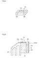
Fig. 4 is a perspective view of thepackage 34 according to Second Embodiment. As illustrated in the view, a pair ofside electrodes 34b are provided on the side surface orthogonalized (intersected) with respect to the majorlight emitting surface 34a in thepackage 34. When the majorlight emitting surface 34a of thepackage 34 and the mountingsurface 36a are not parallel to each other, as illustrated inFigs. 2 and3 , it is difficult to connect, by wire bonding, the majorlight emitting surface 34a and aconductive portion 38a, which is a wiring held by thehousing 38 and is exposed in a region parallel to the mountingsurface 36a. - Accordingly, the
side electrodes 34b in thepackage 34 and theconductive portion 38a in thehousing 38 are connected together with aconductive member 42, such as an Au wire, Al wire, Al ribbon, or the like, in the present embodiment. The connection between the package and the lighting control circuit may be performed with a wiring substrate, or the like, such as an FPC. -
Fig. 5 is a sectional view illustrating the schematic structure near to a light emitting module according to Third Embodiment. In the view, a projection lens and a reflector are omitted. Alight emitting module 50 according to Third Embodiment has a structure almost the same as that of thelight emitting module 28 according to First Embodiment, but is mainly different in that a supportingmember 52, which functions as a heat radiating plate, has a plate (thick plate) shape, not an L-shape. Because the plate-shaped supportingmember 52 does not need bending processing, the processing cost can be more reduced than that of an L-shaped supporting member. Because other structures of thelight emitting module 50 are substantially the same as those of the light emitting module according to First Embodiment, a corresponding structure is denoted with like reference numeral and description thereof will be omitted. -
Fig. 6 is a sectional view illustrating the schematic structure near to a light emitting module according to Fourth Embodiment. In the view, a projection lens and a reflector are omitted. Hereinafter, description will be made, of the structures of alight emitting module 60 according to Fourth Embodiment, centered on the structures different from those of thelight emitting module 28 according to First Embodiment; and a structure thereof similar to that in First Embodiment is denoted with like reference numeral and description thereof will be omitted. - In the supporting
member 24 illustrated inFig. 1 , the wholelighting control circuit 22 is mounted on theplane 24b. However, the heat radiation through the supportingmember 24 can be made even when the whole of a circuit is not necessarily in contact with the supporting member, and in particular, when the calorific power of a circuit is not too large, even part of the circuit may be in contact with the supporting member. Accordingly, in a supportingmember 62 according to the present embodiment, theplane 62b thereof that is in contact with the bottom surface of thelighting control circuit 22 is made small, so that the supporting member is configured to be in contact with part of thelighting control circuit 22. That is, with this structure, the supportingmember 62 is miniaturized. As a result, cost reduction can be made due to reductions in the material cost and the processing cost of the supporting member. -
Fig. 7 is a sectional view illustrating the schematic structure of anautomotive headlamp 70 according to Fourth Embodiment. Hereinafter, a structure similar to that of theautomotive headlamp 10 according to First Embodiment is denoted with like reference numeral and description thereof will be omitted. - The
automotive headlamp 70 comprises acircuit module 72, apackage 16, and areflector 74. Thecircuit module 72 includes: alighting control circuit 22 that controls lighting of a semiconductor light emitting element included in thepackage 16; a supportingmember 76 that supports thepackage 16 and thelighting control circuit 22; and ahousing 26 in which a wiring that electrically connects thepackage 16 and thelighting control circuit 22 is provided. Herein, a module in which thepackage 16 is mounted in thecircuit module 72 is referred to as alight emitting module 78. - The supporting
member 76 is formed by processing a plate-shaped member into an L-shape. The L-shaped supportingmember 76 is processed into a shape in which twoplate portions lighting control circuit 22 is mounted on arear side surface 76c of theplate portion 76a extending in the vertical direction, therear side surface 76c serving as a circuit mounting surface. In addition, thepackage 16 is mounted on alower surface 76d of theplate portion 76b extending in the horizontal direction, thelower surface 76d serving as an element mounting surface. - The
reflector 74 is provided so as to cover thepackage 16 from below, and in the inside of thereflector 74, aparaboloidal surface 74a that collects the light emitted from thepackage 16 by reflecting the light forward. That is, thelight emitting module 78 is arranged such that thelower surface 76d, which is the element mounting surface of the supportingmember 76, faces thereflector 74. Thereby, thereflector 74 controls light distribution by reflecting the light emitted from thepackage 16 with theparaboloidal surface 74a. - In the
circuit module 72 according to the present embodiment, therear side surface 76c, which is the circuit mounting surface of the supportingmember 76, is formed so as to be orthogonalized with respect to thelower surface 76d, which is the element mounting surface of the supportingmember 76. Accordingly, the length in the longitudinal direction of thecircuit module 14 can be made smaller in comparison with that of a circuit module in which a circuit mounting surface and an element mounting surface are formed on the same plane. Alternatively, therear side surface 76c may be formed so as to be inclined with respect to thelower surface 76d. - With such a structure, the
lighting control circuit 22 in thecircuit module 72 or thelight emitting module 78 can be provided on therear side surface 76c, not on the upper surface of the supportingmember 76. As a result, theautomotive headlamp 70 can be made compact in the longitudinal direction thereof and can be miniaturized. In addition to that, because thereflector 74, thepackage 16, and thelighting control circuit 22 can be arranged below theplate portion 76b of the supportingmember 76, theautomotive headlamp 70 can be made compact in the vertical direction and can be further miniaturized. - In each of the aforementioned embodiments, description has been made, assuming that the supporting member has an L-shape; however, it is needless to say that the supporting member may have an inverted L-shape in some cases.
- The present invention has been described above with reference to the aforementioned respective embodiments, but the invention is not limited to the aforementioned respective embodiments, and variations in which each component of the embodiments is appropriately combined or substituted are also encompassed by the invention. In addition, appropriate changes of the combinations or the orders of the processes in the aforementioned embodiments can be made and various modifications, such as design modifications, can be made with respect to the aforementioned embodiments, based on the knowledge of those skilled in the art. Such modified embodiments can also fall in the scope of the invention.
-
- 10
- AUTOMOTIVE HEADLAMP
- 14
- CIRCUIT MODULE
- 16
- PACKAGE
- 18
- REFLECTOR
- 20
- HEAT SINK
- 20a
- UPPER SURFACE
- 20b
- REAR SIDE SURFACE
- 22
- LIGHTING CONTROL CIRCUIT
- 24
- SUPPORTING MEMBER
- 24a, 24b
- PLANE
- 28
- LIGHT EMITTING MODULE
- 32
- CIRCUIT MODULE
- 34a
- MAJOR LIGHT EMITTING SURFACE
- 36a
- MOUNTING SURFACE
- 40
- LIGHT EMITTING MODULE
- The present invention can be used in automotive lamps, etc.
Claims (5)
- A circuit module comprising:a heat radiating plate having both an element mounting surface on which a semiconductor light emitting element can be mounted and a circuit mounting surface on which a lighting control circuit that controls lighting of the semiconductor light emitting element can be mounted; anda lighting control circuit mounted on the circuit mounting surface, wherein the circuit mounting surface is formed so as to be orthogonalized or inclined with respect to the element mounting surface.
- A light emitting module having:the circuit module according to claim 1; anda semiconductor light emitting element mounted on the element mounting surface.
- An automotive lamp to be used in a vehicle, comprising:the light emitting module according to claim 2; anda reflector configured to reflect the light emitted from the light emitting module toward the vehicle front side, whereinthe light emitting module is arranged such that the element mounting surface faces the reflector.
- A light emitting module comprising:a heat radiating plate having a mounting surface on which a component can be mounted;a semiconductor light emitting element mounted on the mounting surface; anda lighting control circuit that is mounted on the mounting surface to control lighting of the semiconductor light emitting element, whereinthe semiconductor light emitting element is arranged such that a major light emitting surface is orthogonalized or inclined with respect to the mounting surface.
- An automotive lamp to be used in a vehicle, comprising:the light emitting module according to claim 4; anda reflector configured to reflect the light emitted from the light emitting module toward the vehicle front side, whereinthe light emitting module is arranged such that the major light emitting surface faces the reflector.
Applications Claiming Priority (2)
| Application Number | Priority Date | Filing Date | Title |
|---|---|---|---|
| JP2010217565A JP5646264B2 (en) | 2010-09-28 | 2010-09-28 | Vehicle lighting |
| PCT/JP2011/005053 WO2012042761A1 (en) | 2010-09-28 | 2011-09-08 | Circuit module, light-emitting module, and vehicle lamp |
Publications (2)
| Publication Number | Publication Date |
|---|---|
| EP2623850A1 true EP2623850A1 (en) | 2013-08-07 |
| EP2623850A4 EP2623850A4 (en) | 2016-03-30 |
Family
ID=45892256
Family Applications (1)
| Application Number | Title | Priority Date | Filing Date |
|---|---|---|---|
| EP11828328.2A Withdrawn EP2623850A4 (en) | 2010-09-28 | 2011-09-08 | Circuit module, light-emitting module, and vehicle lamp |
Country Status (6)
| Country | Link |
|---|---|
| US (1) | US20130201707A1 (en) |
| EP (1) | EP2623850A4 (en) |
| JP (1) | JP5646264B2 (en) |
| KR (1) | KR101548435B1 (en) |
| CN (1) | CN103119356B (en) |
| WO (1) | WO2012042761A1 (en) |
Cited By (4)
| Publication number | Priority date | Publication date | Assignee | Title |
|---|---|---|---|---|
| WO2016124776A1 (en) * | 2015-02-05 | 2016-08-11 | Valeo Vision | Device for connecting a light source to an electrical power supply device |
| FR3056702A1 (en) * | 2016-09-27 | 2018-03-30 | Valeo Vision | LUMINOUS MODULE WITH INTEGRATED DRIVER |
| US10302269B2 (en) | 2014-08-18 | 2019-05-28 | Koito Manufacturing Co., Ltd. | Vehicle lighting device with passage in housing |
| EP3392553A4 (en) * | 2015-12-15 | 2019-08-07 | Koito Manufacturing Co., Ltd. | VEHICLE HEADLIGHT |
Families Citing this family (8)
| Publication number | Priority date | Publication date | Assignee | Title |
|---|---|---|---|---|
| JP5597500B2 (en) * | 2010-09-28 | 2014-10-01 | 株式会社小糸製作所 | Light emitting module and vehicle lamp |
| US9890916B2 (en) | 2012-06-08 | 2018-02-13 | Lg Innotek Co., Ltd. | Lamp unit and vehicle using the same |
| US9194566B2 (en) | 2012-06-08 | 2015-11-24 | Lg Innotek Co., Ltd. | Lamp unit and vehicle lamp apparatus using the same |
| FR2994788B1 (en) * | 2012-08-27 | 2016-09-16 | Valeo Vision | Lighting and / or signaling device for a vehicle comprising a lighting module with a control device removably maintained |
| CN106338043B (en) * | 2015-07-06 | 2020-11-03 | 松下知识产权经营株式会社 | Light source unit, lighting device, and vehicle |
| CN108800039A (en) * | 2018-07-17 | 2018-11-13 | 华域视觉科技(上海)有限公司 | Integrated LED luminescence unit |
| JP7212823B2 (en) * | 2019-03-18 | 2023-01-26 | 株式会社小糸製作所 | Light source module and vehicle lamp |
| CN212805504U (en) * | 2019-07-17 | 2021-03-26 | 株式会社小糸制作所 | Light emitting module and vehicle lamp |
Family Cites Families (29)
| Publication number | Priority date | Publication date | Assignee | Title |
|---|---|---|---|---|
| CZ296081B6 (en) * | 1999-03-24 | 2006-01-11 | Compact structure of motor vehicle LED lamp | |
| JP2000301763A (en) * | 1999-04-23 | 2000-10-31 | Stanley Electric Co Ltd | LED print head |
| US7153004B2 (en) | 2002-12-10 | 2006-12-26 | Galli Robert D | Flashlight housing |
| JP4251941B2 (en) * | 2003-08-08 | 2009-04-08 | 三菱電機株式会社 | head lamp |
| JP2005096161A (en) * | 2003-09-24 | 2005-04-14 | Sanyo Electric Co Ltd | Reel base and recording device using the same |
| US7314296B2 (en) * | 2003-12-08 | 2008-01-01 | Honeywell International Inc. | Multi-platform aircraft forward position light utilizing LED-based light source |
| JP4373822B2 (en) | 2004-03-12 | 2009-11-25 | 株式会社小糸製作所 | Light source module and vehicle lamp |
| US7434970B2 (en) * | 2004-03-12 | 2008-10-14 | Honeywell International Inc. | Multi-platform LED-based aircraft rear position light |
| JP4232725B2 (en) * | 2004-10-13 | 2009-03-04 | 市光工業株式会社 | Projector-type vehicle headlamp unit |
| JP4424148B2 (en) * | 2004-10-13 | 2010-03-03 | 市光工業株式会社 | Projector-type vehicle headlamp unit |
| DE102004056252A1 (en) * | 2004-10-29 | 2006-05-04 | Osram Opto Semiconductors Gmbh | Lighting device, vehicle headlight and method for producing a lighting device |
| JP2006302712A (en) * | 2005-04-21 | 2006-11-02 | Koito Mfg Co Ltd | Vehicle headlamp |
| JP2006331967A (en) * | 2005-05-30 | 2006-12-07 | Sakae Riken Kogyo Co Ltd | Vehicle lighting |
| JP4397856B2 (en) * | 2005-06-06 | 2010-01-13 | 株式会社小糸製作所 | Vehicle lamp and vehicle lamp system |
| DE102005049685A1 (en) * | 2005-10-14 | 2007-04-19 | Patent-Treuhand-Gesellschaft für elektrische Glühlampen mbH | Multifunction vehicle headlamp module, in particular for the front area of a vehicle |
| JP2007141549A (en) * | 2005-11-16 | 2007-06-07 | Koito Mfg Co Ltd | Vehicle lamp |
| US7789530B2 (en) * | 2006-05-02 | 2010-09-07 | Code 3, Inc. | Multi-level modular light bar |
| JP4969958B2 (en) * | 2006-09-13 | 2012-07-04 | 株式会社小糸製作所 | Vehicle lighting |
| AU2007246194A1 (en) * | 2006-12-22 | 2008-07-10 | Rohm And Haas Company | Emulsion based polymer adhesive |
| JP2008166412A (en) * | 2006-12-27 | 2008-07-17 | Koito Mfg Co Ltd | Light emitting element drive circuit and vehicle lamp |
| US20090316384A1 (en) * | 2007-01-12 | 2009-12-24 | Panasonic Corporation | Light-emitting device and illumination apparatus using the same |
| JP4812637B2 (en) * | 2007-01-17 | 2011-11-09 | 株式会社フジクラ | Lighting device |
| JP4881255B2 (en) * | 2007-08-13 | 2012-02-22 | 株式会社小糸製作所 | Vehicle headlamp |
| KR100963966B1 (en) * | 2007-11-21 | 2010-06-15 | 현대모비스 주식회사 | LED unit and light source module having same |
| US7635206B2 (en) * | 2008-01-02 | 2009-12-22 | Yujing Technology Co., Ltd. | Light emitting diode lighting device having a lens connected to a hood |
| US8018136B2 (en) * | 2008-02-28 | 2011-09-13 | Tyco Electronics Corporation | Integrated LED driver for LED socket |
| JP5405043B2 (en) * | 2008-04-22 | 2014-02-05 | 株式会社小糸製作所 | Vehicle lighting |
| JP5177873B2 (en) * | 2008-07-11 | 2013-04-10 | 株式会社小糸製作所 | Vehicle lighting |
| US8123377B2 (en) * | 2008-08-19 | 2012-02-28 | Honeywell International Inc. | Systems and methods for aircraft LED anti collision light |
-
2010
- 2010-09-28 JP JP2010217565A patent/JP5646264B2/en not_active Expired - Fee Related
-
2011
- 2011-09-08 KR KR1020137008325A patent/KR101548435B1/en not_active Expired - Fee Related
- 2011-09-08 WO PCT/JP2011/005053 patent/WO2012042761A1/en not_active Ceased
- 2011-09-08 CN CN201180045638.1A patent/CN103119356B/en not_active Expired - Fee Related
- 2011-09-08 EP EP11828328.2A patent/EP2623850A4/en not_active Withdrawn
-
2013
- 2013-03-15 US US13/838,123 patent/US20130201707A1/en not_active Abandoned
Cited By (7)
| Publication number | Priority date | Publication date | Assignee | Title |
|---|---|---|---|---|
| US10302269B2 (en) | 2014-08-18 | 2019-05-28 | Koito Manufacturing Co., Ltd. | Vehicle lighting device with passage in housing |
| WO2016124776A1 (en) * | 2015-02-05 | 2016-08-11 | Valeo Vision | Device for connecting a light source to an electrical power supply device |
| FR3032561A1 (en) * | 2015-02-05 | 2016-08-12 | Valeo Vision | DEVICE FOR CONNECTING A LIGHT SOURCE TO AN ELECTRIC POWER SUPPLY DEVICE |
| US10337713B2 (en) | 2015-02-05 | 2019-07-02 | Valeo Vision | Device for connecting a light source to an electrical power supply device |
| EP3392553A4 (en) * | 2015-12-15 | 2019-08-07 | Koito Manufacturing Co., Ltd. | VEHICLE HEADLIGHT |
| US10794561B2 (en) | 2015-12-15 | 2020-10-06 | Koito Manufacturing Co., Ltd. | Vehicle lamp |
| FR3056702A1 (en) * | 2016-09-27 | 2018-03-30 | Valeo Vision | LUMINOUS MODULE WITH INTEGRATED DRIVER |
Also Published As
| Publication number | Publication date |
|---|---|
| KR101548435B1 (en) | 2015-08-28 |
| CN103119356B (en) | 2016-02-10 |
| EP2623850A4 (en) | 2016-03-30 |
| WO2012042761A1 (en) | 2012-04-05 |
| CN103119356A (en) | 2013-05-22 |
| JP5646264B2 (en) | 2014-12-24 |
| US20130201707A1 (en) | 2013-08-08 |
| KR20130050997A (en) | 2013-05-16 |
| JP2012074217A (en) | 2012-04-12 |
Similar Documents
| Publication | Publication Date | Title |
|---|---|---|
| US20130201707A1 (en) | Circuit module, light emitting module, and automotive lamp | |
| KR101231406B1 (en) | Car headlight | |
| US7701144B2 (en) | Vehicular lamp | |
| CN102483210B (en) | Luminous device and vehicle headlamp | |
| CN102829417B (en) | Vehicle Headlamps | |
| JP5280087B2 (en) | Equipped flexible electronic support for supporting at least one light emitting diode and method for manufacturing the same | |
| CN102483208B (en) | Automotive headlamps | |
| CN108591961B (en) | Lighting device | |
| CN106338043A (en) | Light Source Unit, Lighting Device, And Vehicle | |
| CN105042468B (en) | Headlight for automobile, cooling mechanism, light-emitting device and light source fixed component | |
| JP2011253622A (en) | Light source unit of semiconductor type light source of lighting fixture for vehicle, lighting fixture for vehicle | |
| JP6209387B2 (en) | Vehicle lighting | |
| US12565974B2 (en) | Lighting module with interconnected PCB assemblies | |
| CN211232730U (en) | Vehicle lamp | |
| WO2024009935A1 (en) | Vehicle light fixture |
Legal Events
| Date | Code | Title | Description |
|---|---|---|---|
| PUAI | Public reference made under article 153(3) epc to a published international application that has entered the european phase |
Free format text: ORIGINAL CODE: 0009012 |
|
| 17P | Request for examination filed |
Effective date: 20130320 |
|
| AK | Designated contracting states |
Kind code of ref document: A1 Designated state(s): AL AT BE BG CH CY CZ DE DK EE ES FI FR GB GR HR HU IE IS IT LI LT LU LV MC MK MT NL NO PL PT RO RS SE SI SK SM TR |
|
| DAX | Request for extension of the european patent (deleted) | ||
| RA4 | Supplementary search report drawn up and despatched (corrected) |
Effective date: 20160225 |
|
| RIC1 | Information provided on ipc code assigned before grant |
Ipc: F21Y 101/00 20160101ALI20160307BHEP Ipc: F21S 8/10 20060101AFI20160307BHEP |
|
| 17Q | First examination report despatched |
Effective date: 20170302 |
|
| GRAP | Despatch of communication of intention to grant a patent |
Free format text: ORIGINAL CODE: EPIDOSNIGR1 |
|
| STAA | Information on the status of an ep patent application or granted ep patent |
Free format text: STATUS: GRANT OF PATENT IS INTENDED |
|
| RIC1 | Information provided on ipc code assigned before grant |
Ipc: F21V 29/70 20150101AFI20200421BHEP Ipc: F21V 23/02 20060101ALI20200421BHEP Ipc: F21Y 101/00 20160101ALI20200421BHEP |
|
| INTG | Intention to grant announced |
Effective date: 20200515 |
|
| STAA | Information on the status of an ep patent application or granted ep patent |
Free format text: STATUS: THE APPLICATION IS DEEMED TO BE WITHDRAWN |
|
| 18D | Application deemed to be withdrawn |
Effective date: 20200926 |