EP2623358A1 - Vehicle drive control device - Google Patents
Vehicle drive control device Download PDFInfo
- Publication number
- EP2623358A1 EP2623358A1 EP11828693.9A EP11828693A EP2623358A1 EP 2623358 A1 EP2623358 A1 EP 2623358A1 EP 11828693 A EP11828693 A EP 11828693A EP 2623358 A1 EP2623358 A1 EP 2623358A1
- Authority
- EP
- European Patent Office
- Prior art keywords
- driving force
- target
- accordance
- vehicle
- command
- Prior art date
- Legal status (The legal status is an assumption and is not a legal conclusion. Google has not performed a legal analysis and makes no representation as to the accuracy of the status listed.)
- Granted
Links
Images


Classifications
-
- B—PERFORMING OPERATIONS; TRANSPORTING
- B60—VEHICLES IN GENERAL
- B60W—CONJOINT CONTROL OF VEHICLE SUB-UNITS OF DIFFERENT TYPE OR DIFFERENT FUNCTION; CONTROL SYSTEMS SPECIALLY ADAPTED FOR HYBRID VEHICLES; ROAD VEHICLE DRIVE CONTROL SYSTEMS FOR PURPOSES NOT RELATED TO THE CONTROL OF A PARTICULAR SUB-UNIT
- B60W20/00—Control systems specially adapted for hybrid vehicles
- B60W20/10—Controlling the power contribution of each of the prime movers to meet required power demand
- B60W20/11—Controlling the power contribution of each of the prime movers to meet required power demand using model predictive control [MPC] strategies, i.e. control methods based on models predicting performance
-
- B—PERFORMING OPERATIONS; TRANSPORTING
- B60—VEHICLES IN GENERAL
- B60K—ARRANGEMENT OR MOUNTING OF PROPULSION UNITS OR OF TRANSMISSIONS IN VEHICLES; ARRANGEMENT OR MOUNTING OF PLURAL DIVERSE PRIME-MOVERS IN VEHICLES; AUXILIARY DRIVES FOR VEHICLES; INSTRUMENTATION OR DASHBOARDS FOR VEHICLES; ARRANGEMENTS IN CONNECTION WITH COOLING, AIR INTAKE, GAS EXHAUST OR FUEL SUPPLY OF PROPULSION UNITS IN VEHICLES
- B60K31/00—Vehicle fittings, acting on a single sub-unit only, for automatically controlling vehicle speed, i.e. preventing speed from exceeding an arbitrarily established velocity or maintaining speed at a particular velocity, as selected by the vehicle operator
-
- B—PERFORMING OPERATIONS; TRANSPORTING
- B60—VEHICLES IN GENERAL
- B60K—ARRANGEMENT OR MOUNTING OF PROPULSION UNITS OR OF TRANSMISSIONS IN VEHICLES; ARRANGEMENT OR MOUNTING OF PLURAL DIVERSE PRIME-MOVERS IN VEHICLES; AUXILIARY DRIVES FOR VEHICLES; INSTRUMENTATION OR DASHBOARDS FOR VEHICLES; ARRANGEMENTS IN CONNECTION WITH COOLING, AIR INTAKE, GAS EXHAUST OR FUEL SUPPLY OF PROPULSION UNITS IN VEHICLES
- B60K6/00—Arrangement or mounting of plural diverse prime-movers for mutual or common propulsion, e.g. hybrid propulsion systems comprising electric motors and internal combustion engines
- B60K6/20—Arrangement or mounting of plural diverse prime-movers for mutual or common propulsion, e.g. hybrid propulsion systems comprising electric motors and internal combustion engines the prime-movers consisting of electric motors and internal combustion engines, e.g. HEVs
- B60K6/42—Arrangement or mounting of plural diverse prime-movers for mutual or common propulsion, e.g. hybrid propulsion systems comprising electric motors and internal combustion engines the prime-movers consisting of electric motors and internal combustion engines, e.g. HEVs characterised by the architecture of the hybrid electric vehicle
- B60K6/48—Parallel type
-
- B—PERFORMING OPERATIONS; TRANSPORTING
- B60—VEHICLES IN GENERAL
- B60L—PROPULSION OF ELECTRICALLY-PROPELLED VEHICLES; SUPPLYING ELECTRIC POWER FOR AUXILIARY EQUIPMENT OF ELECTRICALLY-PROPELLED VEHICLES; ELECTRODYNAMIC BRAKE SYSTEMS FOR VEHICLES IN GENERAL; MAGNETIC SUSPENSION OR LEVITATION FOR VEHICLES; MONITORING OPERATING VARIABLES OF ELECTRICALLY-PROPELLED VEHICLES; ELECTRIC SAFETY DEVICES FOR ELECTRICALLY-PROPELLED VEHICLES
- B60L15/00—Methods, circuits, or devices for controlling the traction-motor speed of electrically-propelled vehicles
- B60L15/20—Methods, circuits, or devices for controlling the traction-motor speed of electrically-propelled vehicles for control of the vehicle or its driving motor to achieve a desired performance, e.g. speed, torque, programmed variation of speed
-
- B—PERFORMING OPERATIONS; TRANSPORTING
- B60—VEHICLES IN GENERAL
- B60L—PROPULSION OF ELECTRICALLY-PROPELLED VEHICLES; SUPPLYING ELECTRIC POWER FOR AUXILIARY EQUIPMENT OF ELECTRICALLY-PROPELLED VEHICLES; ELECTRODYNAMIC BRAKE SYSTEMS FOR VEHICLES IN GENERAL; MAGNETIC SUSPENSION OR LEVITATION FOR VEHICLES; MONITORING OPERATING VARIABLES OF ELECTRICALLY-PROPELLED VEHICLES; ELECTRIC SAFETY DEVICES FOR ELECTRICALLY-PROPELLED VEHICLES
- B60L50/00—Electric propulsion with power supplied within the vehicle
- B60L50/10—Electric propulsion with power supplied within the vehicle using propulsion power supplied by engine-driven generators, e.g. generators driven by combustion engines
- B60L50/16—Electric propulsion with power supplied within the vehicle using propulsion power supplied by engine-driven generators, e.g. generators driven by combustion engines with provision for separate direct mechanical propulsion
-
- B—PERFORMING OPERATIONS; TRANSPORTING
- B60—VEHICLES IN GENERAL
- B60W—CONJOINT CONTROL OF VEHICLE SUB-UNITS OF DIFFERENT TYPE OR DIFFERENT FUNCTION; CONTROL SYSTEMS SPECIALLY ADAPTED FOR HYBRID VEHICLES; ROAD VEHICLE DRIVE CONTROL SYSTEMS FOR PURPOSES NOT RELATED TO THE CONTROL OF A PARTICULAR SUB-UNIT
- B60W10/00—Conjoint control of vehicle sub-units of different type or different function
- B60W10/04—Conjoint control of vehicle sub-units of different type or different function including control of propulsion units
- B60W10/06—Conjoint control of vehicle sub-units of different type or different function including control of propulsion units including control of combustion engines
-
- B—PERFORMING OPERATIONS; TRANSPORTING
- B60—VEHICLES IN GENERAL
- B60W—CONJOINT CONTROL OF VEHICLE SUB-UNITS OF DIFFERENT TYPE OR DIFFERENT FUNCTION; CONTROL SYSTEMS SPECIALLY ADAPTED FOR HYBRID VEHICLES; ROAD VEHICLE DRIVE CONTROL SYSTEMS FOR PURPOSES NOT RELATED TO THE CONTROL OF A PARTICULAR SUB-UNIT
- B60W10/00—Conjoint control of vehicle sub-units of different type or different function
- B60W10/04—Conjoint control of vehicle sub-units of different type or different function including control of propulsion units
- B60W10/08—Conjoint control of vehicle sub-units of different type or different function including control of propulsion units including control of electric propulsion units, e.g. motors or generators
-
- B—PERFORMING OPERATIONS; TRANSPORTING
- B60—VEHICLES IN GENERAL
- B60W—CONJOINT CONTROL OF VEHICLE SUB-UNITS OF DIFFERENT TYPE OR DIFFERENT FUNCTION; CONTROL SYSTEMS SPECIALLY ADAPTED FOR HYBRID VEHICLES; ROAD VEHICLE DRIVE CONTROL SYSTEMS FOR PURPOSES NOT RELATED TO THE CONTROL OF A PARTICULAR SUB-UNIT
- B60W20/00—Control systems specially adapted for hybrid vehicles
- B60W20/10—Controlling the power contribution of each of the prime movers to meet required power demand
-
- B—PERFORMING OPERATIONS; TRANSPORTING
- B60—VEHICLES IN GENERAL
- B60W—CONJOINT CONTROL OF VEHICLE SUB-UNITS OF DIFFERENT TYPE OR DIFFERENT FUNCTION; CONTROL SYSTEMS SPECIALLY ADAPTED FOR HYBRID VEHICLES; ROAD VEHICLE DRIVE CONTROL SYSTEMS FOR PURPOSES NOT RELATED TO THE CONTROL OF A PARTICULAR SUB-UNIT
- B60W30/00—Purposes of road vehicle drive control systems not related to the control of a particular sub-unit, e.g. of systems using conjoint control of vehicle sub-units
- B60W30/14—Adaptive cruise control
- B60W30/16—Control of distance between vehicles, e.g. keeping a distance to preceding vehicle
-
- B—PERFORMING OPERATIONS; TRANSPORTING
- B60—VEHICLES IN GENERAL
- B60K—ARRANGEMENT OR MOUNTING OF PROPULSION UNITS OR OF TRANSMISSIONS IN VEHICLES; ARRANGEMENT OR MOUNTING OF PLURAL DIVERSE PRIME-MOVERS IN VEHICLES; AUXILIARY DRIVES FOR VEHICLES; INSTRUMENTATION OR DASHBOARDS FOR VEHICLES; ARRANGEMENTS IN CONNECTION WITH COOLING, AIR INTAKE, GAS EXHAUST OR FUEL SUPPLY OF PROPULSION UNITS IN VEHICLES
- B60K31/00—Vehicle fittings, acting on a single sub-unit only, for automatically controlling vehicle speed, i.e. preventing speed from exceeding an arbitrarily established velocity or maintaining speed at a particular velocity, as selected by the vehicle operator
- B60K31/0008—Vehicle fittings, acting on a single sub-unit only, for automatically controlling vehicle speed, i.e. preventing speed from exceeding an arbitrarily established velocity or maintaining speed at a particular velocity, as selected by the vehicle operator including means for detecting potential obstacles in vehicle path
- B60K2031/0033—Detecting longitudinal speed or acceleration of target vehicle
-
- B—PERFORMING OPERATIONS; TRANSPORTING
- B60—VEHICLES IN GENERAL
- B60L—PROPULSION OF ELECTRICALLY-PROPELLED VEHICLES; SUPPLYING ELECTRIC POWER FOR AUXILIARY EQUIPMENT OF ELECTRICALLY-PROPELLED VEHICLES; ELECTRODYNAMIC BRAKE SYSTEMS FOR VEHICLES IN GENERAL; MAGNETIC SUSPENSION OR LEVITATION FOR VEHICLES; MONITORING OPERATING VARIABLES OF ELECTRICALLY-PROPELLED VEHICLES; ELECTRIC SAFETY DEVICES FOR ELECTRICALLY-PROPELLED VEHICLES
- B60L2220/00—Electrical machine types; Structures or applications thereof
- B60L2220/40—Electrical machine applications
- B60L2220/46—Wheel motors, i.e. motor connected to only one wheel
-
- B—PERFORMING OPERATIONS; TRANSPORTING
- B60—VEHICLES IN GENERAL
- B60L—PROPULSION OF ELECTRICALLY-PROPELLED VEHICLES; SUPPLYING ELECTRIC POWER FOR AUXILIARY EQUIPMENT OF ELECTRICALLY-PROPELLED VEHICLES; ELECTRODYNAMIC BRAKE SYSTEMS FOR VEHICLES IN GENERAL; MAGNETIC SUSPENSION OR LEVITATION FOR VEHICLES; MONITORING OPERATING VARIABLES OF ELECTRICALLY-PROPELLED VEHICLES; ELECTRIC SAFETY DEVICES FOR ELECTRICALLY-PROPELLED VEHICLES
- B60L2240/00—Control parameters of input or output; Target parameters
- B60L2240/10—Vehicle control parameters
- B60L2240/12—Speed
-
- B—PERFORMING OPERATIONS; TRANSPORTING
- B60—VEHICLES IN GENERAL
- B60L—PROPULSION OF ELECTRICALLY-PROPELLED VEHICLES; SUPPLYING ELECTRIC POWER FOR AUXILIARY EQUIPMENT OF ELECTRICALLY-PROPELLED VEHICLES; ELECTRODYNAMIC BRAKE SYSTEMS FOR VEHICLES IN GENERAL; MAGNETIC SUSPENSION OR LEVITATION FOR VEHICLES; MONITORING OPERATING VARIABLES OF ELECTRICALLY-PROPELLED VEHICLES; ELECTRIC SAFETY DEVICES FOR ELECTRICALLY-PROPELLED VEHICLES
- B60L2240/00—Control parameters of input or output; Target parameters
- B60L2240/40—Drive Train control parameters
- B60L2240/42—Drive Train control parameters related to electric machines
- B60L2240/423—Torque
-
- B—PERFORMING OPERATIONS; TRANSPORTING
- B60—VEHICLES IN GENERAL
- B60L—PROPULSION OF ELECTRICALLY-PROPELLED VEHICLES; SUPPLYING ELECTRIC POWER FOR AUXILIARY EQUIPMENT OF ELECTRICALLY-PROPELLED VEHICLES; ELECTRODYNAMIC BRAKE SYSTEMS FOR VEHICLES IN GENERAL; MAGNETIC SUSPENSION OR LEVITATION FOR VEHICLES; MONITORING OPERATING VARIABLES OF ELECTRICALLY-PROPELLED VEHICLES; ELECTRIC SAFETY DEVICES FOR ELECTRICALLY-PROPELLED VEHICLES
- B60L2250/00—Driver interactions
- B60L2250/10—Driver interactions by alarm
-
- B—PERFORMING OPERATIONS; TRANSPORTING
- B60—VEHICLES IN GENERAL
- B60L—PROPULSION OF ELECTRICALLY-PROPELLED VEHICLES; SUPPLYING ELECTRIC POWER FOR AUXILIARY EQUIPMENT OF ELECTRICALLY-PROPELLED VEHICLES; ELECTRODYNAMIC BRAKE SYSTEMS FOR VEHICLES IN GENERAL; MAGNETIC SUSPENSION OR LEVITATION FOR VEHICLES; MONITORING OPERATING VARIABLES OF ELECTRICALLY-PROPELLED VEHICLES; ELECTRIC SAFETY DEVICES FOR ELECTRICALLY-PROPELLED VEHICLES
- B60L2260/00—Operating Modes
- B60L2260/20—Drive modes; Transition between modes
- B60L2260/28—Four wheel or all wheel drive
-
- B—PERFORMING OPERATIONS; TRANSPORTING
- B60—VEHICLES IN GENERAL
- B60W—CONJOINT CONTROL OF VEHICLE SUB-UNITS OF DIFFERENT TYPE OR DIFFERENT FUNCTION; CONTROL SYSTEMS SPECIALLY ADAPTED FOR HYBRID VEHICLES; ROAD VEHICLE DRIVE CONTROL SYSTEMS FOR PURPOSES NOT RELATED TO THE CONTROL OF A PARTICULAR SUB-UNIT
- B60W2710/00—Output or target parameters relating to a particular sub-units
- B60W2710/10—Change speed gearings
- B60W2710/105—Output torque
-
- B—PERFORMING OPERATIONS; TRANSPORTING
- B60—VEHICLES IN GENERAL
- B60W—CONJOINT CONTROL OF VEHICLE SUB-UNITS OF DIFFERENT TYPE OR DIFFERENT FUNCTION; CONTROL SYSTEMS SPECIALLY ADAPTED FOR HYBRID VEHICLES; ROAD VEHICLE DRIVE CONTROL SYSTEMS FOR PURPOSES NOT RELATED TO THE CONTROL OF A PARTICULAR SUB-UNIT
- B60W2720/00—Output or target parameters relating to overall vehicle dynamics
- B60W2720/10—Longitudinal speed
- B60W2720/106—Longitudinal acceleration
-
- Y—GENERAL TAGGING OF NEW TECHNOLOGICAL DEVELOPMENTS; GENERAL TAGGING OF CROSS-SECTIONAL TECHNOLOGIES SPANNING OVER SEVERAL SECTIONS OF THE IPC; TECHNICAL SUBJECTS COVERED BY FORMER USPC CROSS-REFERENCE ART COLLECTIONS [XRACs] AND DIGESTS
- Y02—TECHNOLOGIES OR APPLICATIONS FOR MITIGATION OR ADAPTATION AGAINST CLIMATE CHANGE
- Y02T—CLIMATE CHANGE MITIGATION TECHNOLOGIES RELATED TO TRANSPORTATION
- Y02T10/00—Road transport of goods or passengers
- Y02T10/60—Other road transportation technologies with climate change mitigation effect
- Y02T10/62—Hybrid vehicles
-
- Y—GENERAL TAGGING OF NEW TECHNOLOGICAL DEVELOPMENTS; GENERAL TAGGING OF CROSS-SECTIONAL TECHNOLOGIES SPANNING OVER SEVERAL SECTIONS OF THE IPC; TECHNICAL SUBJECTS COVERED BY FORMER USPC CROSS-REFERENCE ART COLLECTIONS [XRACs] AND DIGESTS
- Y02—TECHNOLOGIES OR APPLICATIONS FOR MITIGATION OR ADAPTATION AGAINST CLIMATE CHANGE
- Y02T—CLIMATE CHANGE MITIGATION TECHNOLOGIES RELATED TO TRANSPORTATION
- Y02T10/00—Road transport of goods or passengers
- Y02T10/60—Other road transportation technologies with climate change mitigation effect
- Y02T10/64—Electric machine technologies in electromobility
-
- Y—GENERAL TAGGING OF NEW TECHNOLOGICAL DEVELOPMENTS; GENERAL TAGGING OF CROSS-SECTIONAL TECHNOLOGIES SPANNING OVER SEVERAL SECTIONS OF THE IPC; TECHNICAL SUBJECTS COVERED BY FORMER USPC CROSS-REFERENCE ART COLLECTIONS [XRACs] AND DIGESTS
- Y02—TECHNOLOGIES OR APPLICATIONS FOR MITIGATION OR ADAPTATION AGAINST CLIMATE CHANGE
- Y02T—CLIMATE CHANGE MITIGATION TECHNOLOGIES RELATED TO TRANSPORTATION
- Y02T10/00—Road transport of goods or passengers
- Y02T10/60—Other road transportation technologies with climate change mitigation effect
- Y02T10/70—Energy storage systems for electromobility, e.g. batteries
-
- Y—GENERAL TAGGING OF NEW TECHNOLOGICAL DEVELOPMENTS; GENERAL TAGGING OF CROSS-SECTIONAL TECHNOLOGIES SPANNING OVER SEVERAL SECTIONS OF THE IPC; TECHNICAL SUBJECTS COVERED BY FORMER USPC CROSS-REFERENCE ART COLLECTIONS [XRACs] AND DIGESTS
- Y02—TECHNOLOGIES OR APPLICATIONS FOR MITIGATION OR ADAPTATION AGAINST CLIMATE CHANGE
- Y02T—CLIMATE CHANGE MITIGATION TECHNOLOGIES RELATED TO TRANSPORTATION
- Y02T10/00—Road transport of goods or passengers
- Y02T10/60—Other road transportation technologies with climate change mitigation effect
- Y02T10/7072—Electromobility specific charging systems or methods for batteries, ultracapacitors, supercapacitors or double-layer capacitors
-
- Y—GENERAL TAGGING OF NEW TECHNOLOGICAL DEVELOPMENTS; GENERAL TAGGING OF CROSS-SECTIONAL TECHNOLOGIES SPANNING OVER SEVERAL SECTIONS OF THE IPC; TECHNICAL SUBJECTS COVERED BY FORMER USPC CROSS-REFERENCE ART COLLECTIONS [XRACs] AND DIGESTS
- Y02—TECHNOLOGIES OR APPLICATIONS FOR MITIGATION OR ADAPTATION AGAINST CLIMATE CHANGE
- Y02T—CLIMATE CHANGE MITIGATION TECHNOLOGIES RELATED TO TRANSPORTATION
- Y02T10/00—Road transport of goods or passengers
- Y02T10/60—Other road transportation technologies with climate change mitigation effect
- Y02T10/72—Electric energy management in electromobility
-
- Y—GENERAL TAGGING OF NEW TECHNOLOGICAL DEVELOPMENTS; GENERAL TAGGING OF CROSS-SECTIONAL TECHNOLOGIES SPANNING OVER SEVERAL SECTIONS OF THE IPC; TECHNICAL SUBJECTS COVERED BY FORMER USPC CROSS-REFERENCE ART COLLECTIONS [XRACs] AND DIGESTS
- Y10—TECHNICAL SUBJECTS COVERED BY FORMER USPC
- Y10S—TECHNICAL SUBJECTS COVERED BY FORMER USPC CROSS-REFERENCE ART COLLECTIONS [XRACs] AND DIGESTS
- Y10S903/00—Hybrid electric vehicles, HEVS
- Y10S903/902—Prime movers comprising electrical and internal combustion motors
- Y10S903/903—Prime movers comprising electrical and internal combustion motors having energy storing means, e.g. battery, capacitor
- Y10S903/93—Conjoint control of different elements
Definitions
- the present invention relates to a vehicle travel control device mounted on a hybrid vehicle.
- vehicle travel control device that is used in the above-described hybrid vehicle control device to provide travel control of the vehicle in accordance with a vehicle speed and inter-vehicle distance arbitrarily set by a driver of the vehicle.
- This vehicle travel control device can control the acceleration and deceleration of the vehicle in order to follow a preceding vehicle.
- a driving scheme adopted by the vehicle varies with the combination of driving force sources.
- no rotation part is found as the target of a driving force command of a conventional vehicle travel control device.
- the rotation part handled as the target of the driving force command which a driving force source requests from the vehicle travel control device, may change.
- the vehicle travel control device must change the method of calculating the driving force command and output to the driving force source the driving force command for the rotation part, which is a target for which the driving force command is to be requested.
- An object of the present invention is to provide a vehicle travel control device that outputs a driving force command requested for a target by a driving force source, to vehicles having different driving schemes without changing the driving force command calculation method even when the driving force command requested by the driving force source has a different target.
- a vehicle travel control device including a target acceleration computation section and a driving force computation section.
- the target acceleration computation section calculates a target acceleration in accordance with a calculated target vehicle speed and with a detected actual vehicle speed.
- the driving force computation section calculates a driving force command from the target acceleration and outputs the calculated driving force command.
- the driving force computation section includes adjustment means, first conversion means, second conversion means, and output means.
- the adjustment means adjusts a target engine driving force calculated from the target acceleration in accordance with memorized vehicle characteristics and calculates a first driving force command.
- the first conversion means converts the first driving force command to a second driving force command in accordance with a predetermined first conversion ratio.
- the second conversion means converts the second driving force command to a third driving force command in accordance with a predetermined second conversion ratio.
- the output means outputs at least one of the first, second, and third driving force commands in accordance with a connected driving force source.
- the present invention makes it possible to provide a vehicle travel control device that outputs a driving force command requested for a target by a driving force source, to vehicles having different driving schemes without changing the driving force command calculation method even when the driving force command requested by the driving force source has a different target.
- Fig. 1 is a schematic diagram illustrating the configuration of a vehicle travel control device according to the present embodiment.
- the vehicle travel control device is mounted on an automobile or other vehicle. As shown in Fig. 1 , the vehicle travel control device mainly includes a travel control section 1, a vehicle speed sensor 6, an external environment recognition device 7, a driving force distribution device 8, and a driving force source 9 (an engine control section 10, a brake control section 11, and an electric motor control section 12).
- the travel control section 1 is configured in an in-vehicle control unit that controls the travel of an automobile. When a memorized program is executed, the travel control section 1 implements the internal functions of a target inter-vehicle distance computation section 2, a target vehicle speed computation section 3, a target acceleration computation section 4, and a driving force computation section 5.
- Travel control by the travel control section 1 can be either enabled or disabled automatically or in accordance with a user operation.
- a user selects functional settings 14 (e.g., travel control mode, vehicle speed setting, and inter-vehicle distance setting) for travel control purposes.
- Various travel control modes are selectable. More specifically, the user can select, for example, a travel control mode (ACC (Adaptive Cruise Control) mode) that provides control over acceleration and deceleration of the vehicle to follow a preceding vehicle, a travel control mode that provides control over deceleration alone and accelerates the vehicle in accordance with a user operation, and a travel control mode that does not provide control over acceleration or deceleration but issues a warning to alert the user of an approaching preceding vehicle or obstacle.
- the vehicle speed setting can be increased or decreased in units, for instance, of 1 kilometer per hour.
- the inter-vehicle distance which specifies the distance to a preceding vehicle, can be increased or decreased in units, for instance, of 10 meters.
- the vehicle speed sensor 6 is a sensor that measures the traveling speed of the vehicle (actual vehicle speed 15).
- the vehicle speed sensor 6 is configured so that the travel control section 1 acquires information about the measured traveling speed.
- the external environment recognition device 7 includes imaging means (e.g., camera) for acquiring an image ahead of the vehicle and object detection means (e.g., radar) for detecting an object ahead (preceding vehicle or obstacle).
- object detection means e.g., radar
- the external environment recognition device 7 calculates an inter-vehicle distance 16 (the distance to the preceding vehicle or to the object) and a relative speed 17 and outputs information about the calculated inter-vehicle distance 16 and relative speed 17 to the travel control section 1.
- the travel control section 1 then acquires the information.
- the inter-vehicle distance 16 and relative speed 17 may be acquired by one unit of the external environment recognition device 7 or by a plurality of units of the external environment recognition device 7.
- the target vehicle speed computation section 3 calculates a target vehicle speed 23 in accordance with the functional settings 14 by a user operation, the actual vehicle speed 15 acquired from the vehicle speed sensor 6, the inter-vehicle distance 16 and relative speed 17 acquired from the external environment recognition device 7, and a target inter-vehicle distance 22 acquired from the target inter-vehicle distance computation section 2.
- the target acceleration computation section 4 calculates a target acceleration 24 that decreases the difference between the actual vehicle speed 15 and the target vehicle speed 23 calculated by the target vehicle speed computation section 3, and outputs the calculated target acceleration 24 to the driving force computation section 5.
- the driving force computation section 5 calculates a driving force command 18 from the calculated target acceleration 24 in accordance with a vehicle weight and a driving force transmission configuration based on a plurality of conversion ratios (differential gear ratio, gear ratio, torque controller ratio, etc.), and outputs the calculated driving force command 18 to the driving force distribution device 8.
- the driving force distribution device 8 outputs an engine driving force command 19 to the engine control section 10, a brake driving force command 20 to the brake control section 11, and an electric motor driving force command 21 to the electric motor control section 12.
- the engine control section 10 controls the acceleration of the vehicle by controlling the output of an engine in accordance with the engine driving force command 19 from the driving force distribution device 8.
- the brake control section 11 controls the deceleration of the vehicle by braking the vehicle in accordance with the brake driving force command 20 from the driving force distribution device 8.
- Fig. 3 shows a driving scheme that uses the engine 42 as the driving force source 9.
- step S1 of Fig. 2 the target acceleration computation section 4 in the travel control section 1 calculates the target acceleration 24.
- a target wheel driving force (for four wheels) 25 is calculated by multiplying the target acceleration 24, which is calculated by the target acceleration computation section 4, by a memorized vehicle weight of the local vehicle as indicated in Equation (1).
- the target wheel driving force (for four wheels) 25 is a target driving force for wheels (four wheels) 34 or drive shafts (for four wheels) 35 shown in Fig. 3 .
- a target propeller shaft driving force 26 is calculated by dividing the target wheel driving force (for four wheels) 25, which is calculated in step S2, by a memorized differential gear ratio as indicated in Equation (2).
- the target propeller shaft driving force 26 is a target driving force for a propeller shaft 37 shown in Fig. 3 .
- the differential gear ratio indicated in Equation (2) is a ratio at which a differential gear 36 shown in Fig. 3 transmits a driving force from the propeller shaft 37 shown in Fig. 3 to the drive shafts (for four wheels) 35 shown in Fig. 3 .
- Target propeller shaft driving force target wheel driving force / differential gear ratio
- a target transmission input driving force 27 is calculated by dividing the target propeller shaft driving force 26, which is calculated in step S3, by a memorized gear ratio as indicated in Equation (3).
- the target transmission input driving force 27 is a target driving force for a transmission input shaft 39 shown in Fig. 3 .
- the gear ratio indicated in Equation (3) is a ratio at which a driving force is transmitted from a transmission 38 shown in Fig. 3 to the propeller shaft 37 shown in Fig. 3 .
- Target transmission input driving force target propeller shaft driving force / gear ratio
- a target engine driving force 28 is calculated by dividing the target transmission input driving force 27, which is calculated in step S4, by a memorized torque controller ratio as indicated in Equation (4).
- the target engine driving force 28 is a target driving force for a crankshaft 41 shown in Fig. 3 .
- the torque controller ratio indicated in Equation (4) is a ratio at which a driving force is transmitted from the crankshaft 41 shown in Fig. 3 to the transmission input shaft 39 shown in Fig. 3 .
- Target engine driving force target transmission input driving force / torque controller ratio
- adjustment means calculates an engine driving force command 29, which is a first driving force command, by adjusting the target engine driving force 28 in accordance with memorized vehicle characteristics.
- the engine driving force command 29 is a driving force command for the crankshaft 41 shown in Fig. 3 .
- the vehicle characteristics are, for example, the vehicle weight, the radius of a tire, and the speed of vehicle operation response to at least one driving force command value.
- a transmission input driving force command 30, which is a second driving force command is calculated by multiplying the engine driving force command 29, which is the first driving force command calculated in step S6, by the memorized torque controller ratio, which is a first conversion ratio, as indicated in Equation (5).
- the transmission input driving force command 30 is a driving force command for the transmission input shaft 39 shown in Fig. 3 .
- the torque controller ratio indicated in Equation (5) is the same as the torque controller ratio indicated in Equation (4).
- Transmission input driving force command engine driving force command ⁇ torque controller ratio
- a propeller shaft driving force command 31 which is a third driving force command, is calculated by multiplying the transmission input driving force command 30, which is the second driving force command calculated in step S7, by the memorized gear ratio, which is a second conversion ratio, as indicated in Equation (6).
- the propeller shaft driving force command 31 is a driving force command for the propeller shaft 37 shown in Fig. 3 .
- the gear ratio indicated in Equation (6) is the same as the gear ratio indicated in Fig. 3 .
- a wheel driving force command (for four wheels) 32 which is a fourth driving force command, is calculated by multiplying the propeller shaft driving force command 31, which is the third driving force command calculated in step S8, by the memorized differential gear ratio, which is a third conversion ratio, as indicated in Equation (7).
- the wheel driving force command (for four wheels) 32 is a driving force command for the wheels (four wheels) 34 or drive shafts (for four wheels) 35 shown in Fig. 3 .
- the differential gear ratio indicated in Equation (7) is the same as the differential gear ratio indicated in Equation (2).
- Wheel driving force command propeller shaft driving force command ⁇ differential gear ratio
- an acceleration command 33 which is a fifth driving force command, is calculated by dividing the wheel driving force command (for four wheels) 32, which is the fourth driving force command calculated in step S9, by the memorized vehicle weight as indicated in Equation (8).
- the vehicle weight indicated in Equation (8) is the same as the vehicle weight indicated in Equation (1).
- Acceleration command wheel driving force command / vehicle weight
- the above-mentioned torque controller ratio, gear ratio, and differential gear ratio are regarded as the first conversion ratio, the second conversion ratio, and the third conversion ratio, respectively. However, they are not specifically identified as such.
- the differential gear ratio may be regarded as the second conversion ratio.
- the driving force distribution device 8 requests the engine driving force command 29 from the travel control section 1, the output means of the driving force computation section 5 outputs the engine driving force command 29, which is calculated in step S6 of Fig. 2 , to the driving force distribution device 8 as the driving force command 18.
- the output means of the driving force computation section 5 outputs the transmission input driving force command 30, which is calculated in step S7 of Fig. 2 , to the driving force distribution device 8 as the driving force command 18.
- the output means of the driving force computation section 5 outputs the propeller shaft driving force command 31, which is calculated in step S8 of Fig. 2 , to the driving force distribution device 8 as the driving force command 18.
- the output means of the driving force computation section 5 outputs the wheel driving force command (for four wheels) 32, which is calculated in step S9 of Fig. 2 , to the driving force distribution device 8 as the driving force command 18.
- the output means of the driving force computation section 5 outputs the acceleration command 33, which is calculated in step S10 of Fig. 2 , to the driving force distribution device 8 as the driving force command 18.
- Fig. 4 shows a driving scheme that is not provided with an engine and uses an electric motor 43 as the driving force source 9. More specifically, Fig. 4 shows a vehicle that is not equipped with the transmission 38, transmission input shaft 39, torque controller 40, crankshaft 41, and engine 42 shown in Fig. 3 and is provided with the electric motor 43 connected to the propeller shaft 37.
- the vehicle having the driving scheme shown in Fig. 4 virtually has the driving scheme shown in Fig. 3 .
- the driving force computation section 5 may be adapted to automatically set the gear ratio and torque controller ratio to "1".
- An alternative is to allow, for instance, the user to set the gear ratio and torque controller ratio to "1" from the outside. Therefore, the driving force commands indicated in steps S6 to S10 of Fig. 2 can be selected and output in accordance with the request of the driving force distribution device 8 irrespective of the actual driving scheme indicated in Fig. 4 .
- Fig. 5 shows a driving scheme in which electric motors (for four wheels) 44 are used as the driving force source 9 and the driving force of the driving force source 9 is equal to the driving force of the wheels (four wheels) 34 or of the drive shafts (for four wheels) 35. More specifically, Fig. 5 shows a vehicle in which the electric motors (for four wheels) 44 acting as the driving force source are connected to the wheels (four wheels) 34 through the drive shafts (for four wheels) 35.
- the vehicle having the driving scheme shown in Fig. 5 virtually has the driving scheme shown in Fig. 4 .
- the driving force computation section 5 substitutes the value "1" for the gear ratio and for the torque controller ratio, and substitutes the value "3.5" for the differential gear ratio
- the vehicle having the driving scheme shown in Fig. 5 virtually has the driving scheme shown in Fig. 3 .
- the driving force computation section 5 may be adapted to automatically set the gear ratio and torque controller ratio to "1" and the differential gear ratio to "3.5".
- An alternative is to allow, for instance, the user to set the gear ratio and torque controller ratio to "1” and the differential gear ratio to "3.5" from the outside.
- a value other than “0” may be substituted.
- the values "3.5" and “1” are substituted as examples. Any value other than “0” can be substituted because the substituted values offset each other in steps before and after step S6.
- the driving force commands for steps S6 to S10 of Fig. 2 can be selected and output in accordance with the request of the driving force distribution device 8 irrespective of the actual driving scheme indicated in Fig. 5 .
- the driving force computation section 5 in the travel control section 1 shown in Fig. 1 can output the engine driving force command 29, the transmission input driving force command 30, the propeller shaft driving force command 31, the wheel driving force command (for four wheels) 32, or the acceleration command 33 as the driving force command 18 in accordance with the request of the driving force distribution device 8 and with the connected driving force sources 9.
- the driving force command that can be output when an engine automobile having a driving scheme for using an engine as the driving force source is used differs from the driving force command that can be output when an electric automobile having a driving scheme for using an electric motor as the driving force source is used.
- a hybrid automobile having a driving scheme for using both an engine and an electric motor as the driving force source is used, a plurality of driving force commands can be output.
- the vehicle travel control device includes a target acceleration computation section 4 and a driving force computation section 5.
- the target acceleration computation section 4 calculates a target acceleration 24 in accordance with a calculated target vehicle speed 23 and with a detected actual vehicle speed 15.
- the driving force computation section 5 calculates a driving force command 18 from the target acceleration 24 and outputs the calculated driving force command 18.
- the driving force computation section 5 includes adjustment means, first conversion means, second conversion means, and output means.
- the adjustment means adjusts a target engine driving force 28 calculated from the target acceleration 24 in accordance with memorized vehicle characteristics and calculates a first driving force command.
- the first conversion means converts the first driving force command to a second driving force command in accordance with a predetermined first conversion ratio.
- the second conversion means converts the second driving force command to a third driving force command in accordance with a predetermined second conversion ratio.
- the output means outputs at least one of the first, second, and third driving force commands in accordance with a connected driving force source 9.
- the employed configuration which is described above, outputs at least one of a plurality of driving force commands, which are converted by using the predetermined conversion ratios in accordance with the connected driving force source 9, the configuration can be used without changing a driving force command calculation method even when the driving scheme is changed due to a change of the driving force source. Further, a conventional adjustment process can be used.
Landscapes
- Engineering & Computer Science (AREA)
- Transportation (AREA)
- Mechanical Engineering (AREA)
- Chemical & Material Sciences (AREA)
- Combustion & Propulsion (AREA)
- Automation & Control Theory (AREA)
- Power Engineering (AREA)
- Electric Propulsion And Braking For Vehicles (AREA)
- Hybrid Electric Vehicles (AREA)
- Control Of Driving Devices And Active Controlling Of Vehicle (AREA)
- Traffic Control Systems (AREA)
- Controls For Constant Speed Travelling (AREA)
Abstract
Description
- The present invention relates to a vehicle travel control device mounted on a hybrid vehicle.
- There is a known control device for a hybrid vehicle that includes an internal combustion engine and an electric motor as a driving source and travels by transmitting the driving force of either the internal combustion engine or the electric motor to a drive wheel. This control device sets the driving force required for the internal combustion engine and the driving force required for the electric motor in accordance with the operating status of the vehicle (Patent Document 1).
- Also known is a vehicle travel control device that is used in the above-described hybrid vehicle control device to provide travel control of the vehicle in accordance with a vehicle speed and inter-vehicle distance arbitrarily set by a driver of the vehicle. This vehicle travel control device can control the acceleration and deceleration of the vehicle in order to follow a preceding vehicle.
-
- Patent Document 1:
JP-2008-62894-A - When the vehicle has a plurality of different driving force sources, a driving scheme adopted by the vehicle varies with the combination of driving force sources. In a case where a certain driving scheme is adopted, no rotation part is found as the target of a driving force command of a conventional vehicle travel control device.
- In another case, the rotation part handled as the target of the driving force command, which a driving force source requests from the vehicle travel control device, may change. In these cases, the vehicle travel control device must change the method of calculating the driving force command and output to the driving force source the driving force command for the rotation part, which is a target for which the driving force command is to be requested.
- An object of the present invention is to provide a vehicle travel control device that outputs a driving force command requested for a target by a driving force source, to vehicles having different driving schemes without changing the driving force command calculation method even when the driving force command requested by the driving force source has a different target.
- In accomplishing the above object, according to an aspect of the present invention, there is provided a vehicle travel control device including a target acceleration computation section and a driving force computation section. The target acceleration computation section calculates a target acceleration in accordance with a calculated target vehicle speed and with a detected actual vehicle speed. The driving force computation section calculates a driving force command from the target acceleration and outputs the calculated driving force command. The driving force computation section includes adjustment means, first conversion means, second conversion means, and output means. The adjustment means adjusts a target engine driving force calculated from the target acceleration in accordance with memorized vehicle characteristics and calculates a first driving force command. The first conversion means converts the first driving force command to a second driving force command in accordance with a predetermined first conversion ratio.
The second conversion means converts the second driving force command to a third driving force command in accordance with a predetermined second conversion ratio. The output means outputs at least one of the first, second, and third driving force commands in accordance with a connected driving force source. - The present invention makes it possible to provide a vehicle travel control device that outputs a driving force command requested for a target by a driving force source, to vehicles having different driving schemes without changing the driving force command calculation method even when the driving force command requested by the driving force source has a different target.
-
-
Fig. 1 is a schematic diagram illustrating the configuration of an embodiment of a vehicle travel control device according to the present invention. -
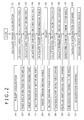
Fig. 2 is a flowchart illustrating how travel control is exercised by the vehicle travel control device according to the present invention. -
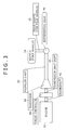
Fig. 3 is a diagram illustrating a driving scheme that uses an engine as a driving force source in the vehicle travel control device according to the present invention. -
Fig. 4 is a diagram illustrating a driving scheme that uses an electric motor as a driving force source in the vehicle travel control device according to the present invention. -
Fig. 5 is a diagram illustrating another driving scheme that uses an electric motor as a driving force source in the vehicle travel control device according to the present invention. - An embodiment of the present invention will now be described with reference to the accompanying drawings.
-
Fig. 1 is a schematic diagram illustrating the configuration of a vehicle travel control device according to the present embodiment. - The vehicle travel control device is mounted on an automobile or other vehicle. As shown in
Fig. 1 , the vehicle travel control device mainly includes atravel control section 1, avehicle speed sensor 6, an externalenvironment recognition device 7, a driving force distribution device 8, and a driving force source 9 (anengine control section 10, abrake control section 11, and an electric motor control section 12). - The
travel control section 1 is configured in an in-vehicle control unit that controls the travel of an automobile. When a memorized program is executed, thetravel control section 1 implements the internal functions of a target inter-vehicle distance computation section 2, a target vehiclespeed computation section 3, a targetacceleration computation section 4, and a drivingforce computation section 5. - Travel control by the
travel control section 1 can be either enabled or disabled automatically or in accordance with a user operation. - A user (driver) selects functional settings 14 (e.g., travel control mode, vehicle speed setting, and inter-vehicle distance setting) for travel control purposes. Various travel control modes are selectable. More specifically, the user can select, for example, a travel control mode (ACC (Adaptive Cruise Control) mode) that provides control over acceleration and deceleration of the vehicle to follow a preceding vehicle, a travel control mode that provides control over deceleration alone and accelerates the vehicle in accordance with a user operation, and a travel control mode that does not provide control over acceleration or deceleration but issues a warning to alert the user of an approaching preceding vehicle or obstacle. The vehicle speed setting can be increased or decreased in units, for instance, of 1 kilometer per hour. The inter-vehicle distance, which specifies the distance to a preceding vehicle, can be increased or decreased in units, for instance, of 10 meters.
- The
vehicle speed sensor 6 is a sensor that measures the traveling speed of the vehicle (actual vehicle speed 15). Thevehicle speed sensor 6 is configured so that thetravel control section 1 acquires information about the measured traveling speed. The externalenvironment recognition device 7 includes imaging means (e.g., camera) for acquiring an image ahead of the vehicle and object detection means (e.g., radar) for detecting an object ahead (preceding vehicle or obstacle). As regards a preceding vehicle traveling ahead of the local vehicle or an object stopped ahead of the local vehicle, the externalenvironment recognition device 7 calculates an inter-vehicle distance 16 (the distance to the preceding vehicle or to the object) and arelative speed 17 and outputs information about the calculatedinter-vehicle distance 16 andrelative speed 17 to thetravel control section 1. Thetravel control section 1 then acquires the information. Theinter-vehicle distance 16 andrelative speed 17 may be acquired by one unit of the externalenvironment recognition device 7 or by a plurality of units of the externalenvironment recognition device 7. - The target vehicle
speed computation section 3 calculates atarget vehicle speed 23 in accordance with thefunctional settings 14 by a user operation, theactual vehicle speed 15 acquired from thevehicle speed sensor 6, theinter-vehicle distance 16 andrelative speed 17 acquired from the externalenvironment recognition device 7, and a targetinter-vehicle distance 22 acquired from the target inter-vehicle distance computation section 2. The targetacceleration computation section 4 calculates atarget acceleration 24 that decreases the difference between theactual vehicle speed 15 and thetarget vehicle speed 23 calculated by the target vehiclespeed computation section 3, and outputs the calculatedtarget acceleration 24 to the drivingforce computation section 5. - The driving
force computation section 5 calculates adriving force command 18 from the calculatedtarget acceleration 24 in accordance with a vehicle weight and a driving force transmission configuration based on a plurality of conversion ratios (differential gear ratio, gear ratio, torque controller ratio, etc.), and outputs the calculateddriving force command 18 to the driving force distribution device 8. - In accordance with the
driving force command 18 calculated by thetravel control section 1, the driving force distribution device 8 outputs an enginedriving force command 19 to theengine control section 10, a brakedriving force command 20 to thebrake control section 11, and an electric motordriving force command 21 to the electricmotor control section 12. - The
engine control section 10 controls the acceleration of the vehicle by controlling the output of an engine in accordance with the enginedriving force command 19 from the driving force distribution device 8. Thebrake control section 11 controls the deceleration of the vehicle by braking the vehicle in accordance with the brakedriving force command 20 from the driving force distribution device 8. The electricmotor control section 12, which functions as an electric motor and as a power generator, controls the acceleration and deceleration of the vehicle in accordance with the electric motordriving force command 21 from the driving force distribution device 8. - A method of calculating the
driving force command 18, which is output from thetravel control section 1 according to the present embodiment, will now be described with reference to the flowchart ofFig. 2 and a driving force transmission configuration diagram ofFig. 3. Fig. 3 shows a driving scheme that uses theengine 42 as thedriving force source 9. - In step S1 of
Fig. 2 , the targetacceleration computation section 4 in thetravel control section 1 calculates thetarget acceleration 24. - In step S2 of
Fig. 2 , a target wheel driving force (for four wheels) 25 is calculated by multiplying thetarget acceleration 24, which is calculated by the targetacceleration computation section 4, by a memorized vehicle weight of the local vehicle as indicated in Equation (1). The target wheel driving force (for four wheels) 25 is a target driving force for wheels (four wheels) 34 or drive shafts (for four wheels) 35 shown inFig. 3 . -

Fig. 2 , a target propeller shaftdriving force 26 is calculated by dividing the target wheel driving force (for four wheels) 25, which is calculated in step S2, by a memorized differential gear ratio as indicated in Equation (2). The target propeller shaftdriving force 26 is a target driving force for apropeller shaft 37 shown inFig. 3 . The differential gear ratio indicated in Equation (2) is a ratio at which adifferential gear 36 shown inFig. 3 transmits a driving force from thepropeller shaft 37 shown inFig. 3 to the drive shafts (for four wheels) 35 shown inFig. 3 . -

input driving force 27 is calculated by dividing the target propellershaft driving force 26, which is calculated in step S3, by a memorized gear ratio as indicated in Equation (3). The target transmissioninput driving force 27 is a target driving force for atransmission input shaft 39 shown inFig. 3 . The gear ratio indicated in Equation (3) is a ratio at which a driving force is transmitted from atransmission 38 shown inFig. 3 to thepropeller shaft 37 shown inFig. 3 . -

engine driving force 28 is calculated by dividing the target transmissioninput driving force 27, which is calculated in step S4, by a memorized torque controller ratio as indicated in Equation (4). The targetengine driving force 28 is a target driving force for acrankshaft 41 shown inFig. 3 . The torque controller ratio indicated in Equation (4) is a ratio at which a driving force is transmitted from thecrankshaft 41 shown inFig. 3 to thetransmission input shaft 39 shown inFig. 3 . -

force command 29, which is a first driving force command, by adjusting the targetengine driving force 28 in accordance with memorized vehicle characteristics. The engine drivingforce command 29 is a driving force command for thecrankshaft 41 shown inFig. 3 . The vehicle characteristics are, for example, the vehicle weight, the radius of a tire, and the speed of vehicle operation response to at least one driving force command value. - In step S7, a transmission input driving
force command 30, which is a second driving force command, is calculated by multiplying the engine drivingforce command 29, which is the first driving force command calculated in step S6, by the memorized torque controller ratio, which is a first conversion ratio, as indicated in Equation (5). The transmission input drivingforce command 30 is a driving force command for thetransmission input shaft 39 shown inFig. 3 . The torque controller ratio indicated in Equation (5) is the same as the torque controller ratio indicated in Equation (4). -

force command 31, which is a third driving force command, is calculated by multiplying the transmission input drivingforce command 30, which is the second driving force command calculated in step S7, by the memorized gear ratio, which is a second conversion ratio, as indicated in Equation (6). The propeller shaft drivingforce command 31 is a driving force command for thepropeller shaft 37 shown inFig. 3 . The gear ratio indicated in Equation (6) is the same as the gear ratio indicated inFig. 3 . -

force command 31, which is the third driving force command calculated in step S8, by the memorized differential gear ratio, which is a third conversion ratio, as indicated in Equation (7). The wheel driving force command (for four wheels) 32 is a driving force command for the wheels (four wheels) 34 or drive shafts (for four wheels) 35 shown inFig. 3 . The differential gear ratio indicated in Equation (7) is the same as the differential gear ratio indicated in Equation (2). -

acceleration command 33, which is a fifth driving force command, is calculated by dividing the wheel driving force command (for four wheels) 32, which is the fourth driving force command calculated in step S9, by the memorized vehicle weight as indicated in Equation (8). The vehicle weight indicated in Equation (8) is the same as the vehicle weight indicated in Equation (1). -

- The same also holds true for a plurality of driving force commands such as the above-mentioned first to fifth driving force commands.
- Details of the embodiment of the vehicle travel control device will now be described.
- First of all, when, in a vehicle having a driving scheme that uses the
engine 42 as the drivingforce source 9 as shown inFig. 3 , the driving force distribution device 8 requests the engine drivingforce command 29 from thetravel control section 1, the output means of the drivingforce computation section 5 outputs the engine drivingforce command 29, which is calculated in step S6 ofFig. 2 , to the driving force distribution device 8 as the drivingforce command 18. - When the driving force distribution device 8 requests the transmission input driving
force command 30 from thetravel control section 1, the output means of the drivingforce computation section 5 outputs the transmission input drivingforce command 30, which is calculated in step S7 ofFig. 2 , to the driving force distribution device 8 as the drivingforce command 18. - When the driving force distribution device 8 requests the propeller shaft driving
force command 31 from thetravel control section 1, the output means of the drivingforce computation section 5 outputs the propeller shaft drivingforce command 31, which is calculated in step S8 ofFig. 2 , to the driving force distribution device 8 as the drivingforce command 18. - When the driving force distribution device 8 requests the wheel driving force command (for four wheels) 32 from the
travel control section 1, the output means of the drivingforce computation section 5 outputs the wheel driving force command (for four wheels) 32, which is calculated in step S9 ofFig. 2 , to the driving force distribution device 8 as the drivingforce command 18. - When the driving force distribution device 8 requests the
acceleration command 33 from thetravel control section 1, the output means of the drivingforce computation section 5 outputs theacceleration command 33, which is calculated in step S10 ofFig. 2 , to the driving force distribution device 8 as the drivingforce command 18. -
Fig. 4 shows a driving scheme that is not provided with an engine and uses anelectric motor 43 as the drivingforce source 9. More specifically,Fig. 4 shows a vehicle that is not equipped with thetransmission 38,transmission input shaft 39,torque controller 40,crankshaft 41, andengine 42 shown inFig. 3 and is provided with theelectric motor 43 connected to thepropeller shaft 37. - When the driving
force computation section 5 substitutes the value "1" for the gear ratio and for the torque controller ratio, the vehicle having the driving scheme shown inFig. 4 virtually has the driving scheme shown inFig. 3 . When thetravel control section 1 recognizes that the employed driving scheme connects theelectric motor 43 as the drivingforce source 9, the drivingforce computation section 5 may be adapted to automatically set the gear ratio and torque controller ratio to "1". An alternative is to allow, for instance, the user to set the gear ratio and torque controller ratio to "1" from the outside. Therefore, the driving force commands indicated in steps S6 to S10 ofFig. 2 can be selected and output in accordance with the request of the driving force distribution device 8 irrespective of the actual driving scheme indicated inFig. 4 . -
Fig. 5 shows a driving scheme in which electric motors (for four wheels) 44 are used as the drivingforce source 9 and the driving force of the drivingforce source 9 is equal to the driving force of the wheels (four wheels) 34 or of the drive shafts (for four wheels) 35. More specifically,Fig. 5 shows a vehicle in which the electric motors (for four wheels) 44 acting as the driving force source are connected to the wheels (four wheels) 34 through the drive shafts (for four wheels) 35. - When the driving
force computation section 5 substitutes the value "3.5" for the differential gear ratio, the vehicle having the driving scheme shown inFig. 5 virtually has the driving scheme shown inFig. 4 . In other words, when the drivingforce computation section 5 substitutes the value "1" for the gear ratio and for the torque controller ratio, and substitutes the value "3.5" for the differential gear ratio, the vehicle having the driving scheme shown inFig. 5 virtually has the driving scheme shown inFig. 3 . - When the
travel control section 1 recognizes that the employed driving scheme connects the drivingforce source 9 shown inFig. 5 , the drivingforce computation section 5 may be adapted to automatically set the gear ratio and torque controller ratio to "1" and the differential gear ratio to "3.5". An alternative is to allow, for instance, the user to set the gear ratio and torque controller ratio to "1" and the differential gear ratio to "3.5" from the outside. - Instead of the values "3.5" and "1", a value other than "0" may be substituted. In the present embodiment, the values "3.5" and "1" are substituted as examples. Any value other than "0" can be substituted because the substituted values offset each other in steps before and after step S6.
- Consequently, the driving force commands for steps S6 to S10 of
Fig. 2 can be selected and output in accordance with the request of the driving force distribution device 8 irrespective of the actual driving scheme indicated inFig. 5 . - More specifically, the driving
force computation section 5 in thetravel control section 1 shown inFig. 1 can output the engine drivingforce command 29, the transmission input drivingforce command 30, the propeller shaft drivingforce command 31, the wheel driving force command (for four wheels) 32, or theacceleration command 33 as the drivingforce command 18 in accordance with the request of the driving force distribution device 8 and with the connected drivingforce sources 9. - For example, the driving force command that can be output when an engine automobile having a driving scheme for using an engine as the driving force source is used differs from the driving force command that can be output when an electric automobile having a driving scheme for using an electric motor as the driving force source is used. When a hybrid automobile having a driving scheme for using both an engine and an electric motor as the driving force source is used, a plurality of driving force commands can be output.
- The vehicle travel control device according to the present invention, which has been described above, includes a target
acceleration computation section 4 and a drivingforce computation section 5. The targetacceleration computation section 4 calculates atarget acceleration 24 in accordance with a calculatedtarget vehicle speed 23 and with a detectedactual vehicle speed 15. The drivingforce computation section 5 calculates a drivingforce command 18 from thetarget acceleration 24 and outputs the calculated drivingforce command 18. The drivingforce computation section 5 includes adjustment means, first conversion means, second conversion means, and output means. The adjustment means adjusts a targetengine driving force 28 calculated from thetarget acceleration 24 in accordance with memorized vehicle characteristics and calculates a first driving force command. The first conversion means converts the first driving force command to a second driving force command in accordance with a predetermined first conversion ratio. The second conversion means converts the second driving force command to a third driving force command in accordance with a predetermined second conversion ratio. The output means outputs at least one of the first, second, and third driving force commands in accordance with a connected drivingforce source 9. When the employed configuration, which is described above, outputs at least one of a plurality of driving force commands, which are converted by using the predetermined conversion ratios in accordance with the connected drivingforce source 9, the configuration can be used without changing a driving force command calculation method even when the driving scheme is changed due to a change of the driving force source. Further, a conventional adjustment process can be used. -
- 1
- Travel control section
- 2
- Target inter-vehicle distance computation section
- 3
- Target vehicle speed computation section
- 4
- Target acceleration computation section
- 5
- Driving force computation section
- 6
- Vehicle speed sensor
- 7
- External environment recognition device
- 8
- Driving force distribution device
- 9
- Driving force source
- 10
- Engine control section
- 11
- Brake control section
- 12
- Electric motor control section
- 14
- Functional settings
- 15
- Actual vehicle speed
- 16
- Inter-vehicle distance
- 17
- Relative speed
- 18
- Driving force command
- 19
- Engine driving force command
- 20
- Brake driving force command
- 21
- Electric motor driving force command
- 22
- Target inter-vehicle distance
- 23
- Target vehicle speed
- 24
- Target acceleration
Claims (7)
- A vehicle travel control device comprising:a target acceleration computation section for calculating a target acceleration in accordance with a calculated target vehicle speed and with a detected actual vehicle speed; anda driving force computation section for calculating a driving force command from the target acceleration and outputting the calculated driving force command;wherein the driving force computation section includesadjustment means for adjusting a target engine driving force calculated from the target acceleration in accordance with memorized vehicle characteristics and calculating a first driving force command,first conversion means for converting the first driving force command to a second driving force command in accordance with a predetermined first conversion ratio,second conversion means for converting the second driving force command to a third driving force command in accordance with a predetermined second conversion ratio, andoutput means for outputting at least one of the first, second, and third driving force commands in accordance with a connected driving force source.
- The vehicle travel control device according to claim 1,
wherein the driving force computation section further includes
third conversion means for converting the third driving force command to a fourth driving force command in accordance with a predetermined third conversion ratio, and
driving force command calculation means for calculating a fifth driving force command in accordance with the fourth driving force command and with a memorized vehicle weight; and
wherein the output means outputs at least one of the first, second, third, fourth, and fifth driving force commands in accordance with the connected driving force source. - The vehicle travel control device according to claim 1,
wherein the driving force computation section further includes
target wheel driving force calculation means for generating a target wheel driving force in accordance with the target acceleration and with a predetermined vehicle weight,
first driving force conversion means for converting the target wheel driving force to a first target driving force in accordance with the first conversion ratio, and
second driving force conversion means for converting the first target driving force to a target engine driving force in accordance with the second conversion ratio. - The vehicle travel control device according to claim 2,
wherein the driving force computation section further includes
target wheel driving force calculation means for generating a target wheel driving force in accordance with the target acceleration and with a predetermined vehicle weight,
first driving force conversion means for converting the target wheel driving force to a first target driving force in accordance with the first conversion ratio,
second driving force conversion means for converting the first target driving force to a second target driving force in accordance with the second conversion ratio, and
third driving force conversion means for converting the second target driving force to a target engine driving force in accordance with the third conversion ratio. - The vehicle travel control device according to claim 1,
wherein the vehicle characteristics are a memorized vehicle weight, a memorized tire radius, and a memorized speed of vehicle operation response to at least one driving force command value. - The vehicle travel control device according to claim 1,
wherein the driving force command output from the output means varies depending on whether the employed driving scheme connects an engine or an electric motor as a driving force source. - The vehicle travel control device according to claim 1,
wherein the output means outputs a plurality of driving force commands when the employed driving scheme connects both an engine and an electric motor as a driving force source.
Applications Claiming Priority (2)
| Application Number | Priority Date | Filing Date | Title |
|---|---|---|---|
| JP2010218054A JP5520766B2 (en) | 2010-09-29 | 2010-09-29 | Vehicle travel control device |
| PCT/JP2011/069961 WO2012043132A1 (en) | 2010-09-29 | 2011-09-01 | Vehicle drive control device |
Publications (3)
| Publication Number | Publication Date |
|---|---|
| EP2623358A1 true EP2623358A1 (en) | 2013-08-07 |
| EP2623358A4 EP2623358A4 (en) | 2018-05-02 |
| EP2623358B1 EP2623358B1 (en) | 2021-11-17 |
Family
ID=45892605
Family Applications (1)
| Application Number | Title | Priority Date | Filing Date |
|---|---|---|---|
| EP11828693.9A Active EP2623358B1 (en) | 2010-09-29 | 2011-09-01 | Vehicle drive control device |
Country Status (4)
| Country | Link |
|---|---|
| US (1) | US9045133B2 (en) |
| EP (1) | EP2623358B1 (en) |
| JP (1) | JP5520766B2 (en) |
| WO (1) | WO2012043132A1 (en) |
Families Citing this family (4)
| Publication number | Priority date | Publication date | Assignee | Title |
|---|---|---|---|---|
| WO2015111341A1 (en) * | 2014-01-22 | 2015-07-30 | カルソニックカンセイ株式会社 | Driving force controller for electric vehicle |
| DE102014014241A1 (en) * | 2014-09-25 | 2016-03-31 | Audi Ag | Method for driver information and motor vehicle |
| KR102371248B1 (en) * | 2017-09-08 | 2022-03-04 | 현대자동차 주식회사 | Method for controlling e-4wd hybrid vehicle |
| JP7835200B2 (en) * | 2023-05-22 | 2026-03-25 | トヨタ自動車株式会社 | Vehicle information processing device and information processing system |
Family Cites Families (15)
| Publication number | Priority date | Publication date | Assignee | Title |
|---|---|---|---|---|
| JP3236344B2 (en) * | 1992-05-13 | 2001-12-10 | 本田技研工業株式会社 | Power source output control device for vehicle |
| JP3127350B2 (en) * | 1995-07-20 | 2001-01-22 | 本田技研工業株式会社 | Control device for lock-up clutch |
| US6066070A (en) * | 1998-04-28 | 2000-05-23 | Toyota Jidosha Kabushiki Kaisha | Control system of vehicle having continuously variable transmission |
| WO1999058359A1 (en) * | 1998-05-11 | 1999-11-18 | Hitachi, Ltd. | Vehicle and device and method for controlling running of the same |
| JP3811296B2 (en) * | 1998-09-09 | 2006-08-16 | 株式会社日立製作所 | Driving control device for automobile |
| JP3543678B2 (en) * | 1998-12-16 | 2004-07-14 | 日産自動車株式会社 | Vehicle driving force control device |
| JP3815111B2 (en) * | 1999-04-16 | 2006-08-30 | 日産自動車株式会社 | Vehicle driving force control device |
| JP3890847B2 (en) * | 2000-02-29 | 2007-03-07 | 株式会社日立製作所 | Automotive control device |
| JP3582462B2 (en) * | 2000-07-04 | 2004-10-27 | 日産自動車株式会社 | Vehicle speed control device |
| JP4857518B2 (en) * | 2003-12-24 | 2012-01-18 | トヨタ自動車株式会社 | Vehicle control device |
| JP2006298317A (en) * | 2005-04-25 | 2006-11-02 | Toyota Motor Corp | Driving force control device |
| JP2007232098A (en) * | 2006-03-01 | 2007-09-13 | Toyota Motor Corp | Vehicle control device |
| JP2007255382A (en) * | 2006-03-24 | 2007-10-04 | Toyota Motor Corp | Vehicle travel control device and vehicle travel control method |
| JP4377898B2 (en) | 2006-09-11 | 2009-12-02 | 本田技研工業株式会社 | Control device for hybrid vehicle |
| JP4862630B2 (en) * | 2006-11-27 | 2012-01-25 | 株式会社デンソー | Inter-vehicle distance control device |
-
2010
- 2010-09-29 JP JP2010218054A patent/JP5520766B2/en active Active
-
2011
- 2011-09-01 US US13/818,582 patent/US9045133B2/en active Active
- 2011-09-01 WO PCT/JP2011/069961 patent/WO2012043132A1/en not_active Ceased
- 2011-09-01 EP EP11828693.9A patent/EP2623358B1/en active Active
Non-Patent Citations (1)
| Title |
|---|
| See references of WO2012043132A1 * |
Also Published As
| Publication number | Publication date |
|---|---|
| EP2623358A4 (en) | 2018-05-02 |
| WO2012043132A1 (en) | 2012-04-05 |
| US20130211652A1 (en) | 2013-08-15 |
| JP2012071684A (en) | 2012-04-12 |
| EP2623358B1 (en) | 2021-11-17 |
| US9045133B2 (en) | 2015-06-02 |
| JP5520766B2 (en) | 2014-06-11 |
Similar Documents
| Publication | Publication Date | Title |
|---|---|---|
| EP2782083B1 (en) | Driving assistance device | |
| EP2782084B1 (en) | Driving support apparatus | |
| CN106163852B (en) | Method for driving an electric motor in a series hybrid vehicle or a fully electric vehicle with at least two separately driven axles | |
| US10293817B2 (en) | Control unit for a vehicle | |
| JP6304193B2 (en) | Vehicle control device | |
| EP3121423B1 (en) | Driving assistance apparatus for vehicle | |
| US20140288758A1 (en) | Electric vehicle control device | |
| US20180056811A1 (en) | Drive power control device for electric vehicle | |
| CN106515733B (en) | The control device of vehicle | |
| JP6265191B2 (en) | Vehicle control device | |
| EP3677481A1 (en) | System and method for torque split arbitration | |
| CN107021100B (en) | Systems and methods for uphill speed assist | |
| CN106976455A (en) | Vehicle speed control system | |
| CN115092137A (en) | Vehicle drive force control device | |
| US8996221B2 (en) | Method for traction control in a motor vehicle, and control system for carrying out the method | |
| EP2623358B1 (en) | Vehicle drive control device | |
| CN112399940A (en) | Driving control device, vehicle, driving assistance device, and driving control method | |
| JP7472892B2 (en) | Driving force control device | |
| CN116279419A (en) | Vehicle control device, vehicle control method, and non-transitory storage medium | |
| JP2021079746A (en) | Control device of vehicle | |
| JP2004299593A (en) | Inter-vehicle distance keeping automatic controller | |
| KR20120047522A (en) | System and the method of generating reference speed for automatic driving vehicle | |
| SE1251110A1 (en) | Apparatus and method for convenient and / or fuel saving driving of a motor vehicle | |
| JP2017047795A (en) | Vehicular travel control apparatus | |
| US20180281792A1 (en) | Method for automatically adjusting the vehicle speed |
Legal Events
| Date | Code | Title | Description |
|---|---|---|---|
| PUAI | Public reference made under article 153(3) epc to a published international application that has entered the european phase |
Free format text: ORIGINAL CODE: 0009012 |
|
| 17P | Request for examination filed |
Effective date: 20130429 |
|
| AK | Designated contracting states |
Kind code of ref document: A1 Designated state(s): AL AT BE BG CH CY CZ DE DK EE ES FI FR GB GR HR HU IE IS IT LI LT LU LV MC MK MT NL NO PL PT RO RS SE SI SK SM TR |
|
| DAX | Request for extension of the european patent (deleted) | ||
| RA4 | Supplementary search report drawn up and despatched (corrected) |
Effective date: 20180404 |
|
| RIC1 | Information provided on ipc code assigned before grant |
Ipc: B60K 31/00 20060101AFI20180327BHEP Ipc: B60W 30/14 20060101ALI20180327BHEP Ipc: B60W 10/06 20060101ALI20180327BHEP Ipc: B60L 15/20 20060101ALI20180327BHEP Ipc: B60K 6/48 20071001ALI20180327BHEP Ipc: B60W 20/11 20160101ALI20180327BHEP Ipc: B60W 30/16 20120101ALI20180327BHEP Ipc: B60W 10/08 20060101ALI20180327BHEP Ipc: B60W 20/00 20060101ALI20180327BHEP Ipc: B60K 6/54 20071001ALI20180327BHEP Ipc: B60L 11/14 20060101ALI20180327BHEP Ipc: B60W 30/18 20120101ALI20180327BHEP |
|
| RIC1 | Information provided on ipc code assigned before grant |
Ipc: B60W 10/08 20060101ALI20180327BHEP Ipc: B60W 10/06 20060101ALI20180327BHEP Ipc: B60W 30/16 20120101ALI20180327BHEP Ipc: B60W 30/14 20060101ALI20180327BHEP Ipc: B60W 20/11 20160101ALI20180327BHEP Ipc: B60W 20/00 20160101ALI20180327BHEP Ipc: B60L 11/14 20060101ALI20180327BHEP Ipc: B60K 31/00 20060101AFI20180327BHEP Ipc: B60K 6/48 20071001ALI20180327BHEP Ipc: B60W 30/18 20120101ALI20180327BHEP Ipc: B60K 6/54 20071001ALI20180327BHEP Ipc: B60L 15/20 20060101ALI20180327BHEP |
|
| REG | Reference to a national code |
Ref country code: DE Ref legal event code: R079 Ref document number: 602011072129 Country of ref document: DE Free format text: PREVIOUS MAIN CLASS: B60K0031000000 Ipc: B60K0006480000 |
|
| RIC1 | Information provided on ipc code assigned before grant |
Ipc: B60L 50/16 20190101ALI20210617BHEP Ipc: B60W 30/14 20060101ALI20210617BHEP Ipc: B60W 20/00 20160101ALI20210617BHEP Ipc: B60W 10/08 20060101ALI20210617BHEP Ipc: B60W 10/06 20060101ALI20210617BHEP Ipc: B60L 15/20 20060101ALI20210617BHEP Ipc: B60K 31/00 20060101ALI20210617BHEP Ipc: B60K 6/48 20071001AFI20210617BHEP |
|
| GRAP | Despatch of communication of intention to grant a patent |
Free format text: ORIGINAL CODE: EPIDOSNIGR1 |
|
| STAA | Information on the status of an ep patent application or granted ep patent |
Free format text: STATUS: GRANT OF PATENT IS INTENDED |
|
| INTG | Intention to grant announced |
Effective date: 20210802 |
|
| RAP3 | Party data changed (applicant data changed or rights of an application transferred) |
Owner name: HITACHI ASTEMO, LTD. |
|
| GRAS | Grant fee paid |
Free format text: ORIGINAL CODE: EPIDOSNIGR3 |
|
| GRAA | (expected) grant |
Free format text: ORIGINAL CODE: 0009210 |
|
| STAA | Information on the status of an ep patent application or granted ep patent |
Free format text: STATUS: THE PATENT HAS BEEN GRANTED |
|
| RIN1 | Information on inventor provided before grant (corrected) |
Inventor name: SHIBATA TAKEO |
|
| AK | Designated contracting states |
Kind code of ref document: B1 Designated state(s): AL AT BE BG CH CY CZ DE DK EE ES FI FR GB GR HR HU IE IS IT LI LT LU LV MC MK MT NL NO PL PT RO RS SE SI SK SM TR |
|
| REG | Reference to a national code |
Ref country code: GB Ref legal event code: FG4D |
|
| REG | Reference to a national code |
Ref country code: DE Ref legal event code: R096 Ref document number: 602011072129 Country of ref document: DE |
|
| REG | Reference to a national code |
Ref country code: IE Ref legal event code: FG4D |
|
| REG | Reference to a national code |
Ref country code: AT Ref legal event code: REF Ref document number: 1447761 Country of ref document: AT Kind code of ref document: T Effective date: 20211215 |
|
| REG | Reference to a national code |
Ref country code: LT Ref legal event code: MG9D |
|
| REG | Reference to a national code |
Ref country code: NL Ref legal event code: MP Effective date: 20211117 |
|
| REG | Reference to a national code |
Ref country code: AT Ref legal event code: MK05 Ref document number: 1447761 Country of ref document: AT Kind code of ref document: T Effective date: 20211117 |
|
| PG25 | Lapsed in a contracting state [announced via postgrant information from national office to epo] |
Ref country code: RS Free format text: LAPSE BECAUSE OF FAILURE TO SUBMIT A TRANSLATION OF THE DESCRIPTION OR TO PAY THE FEE WITHIN THE PRESCRIBED TIME-LIMIT Effective date: 20211117 Ref country code: LT Free format text: LAPSE BECAUSE OF FAILURE TO SUBMIT A TRANSLATION OF THE DESCRIPTION OR TO PAY THE FEE WITHIN THE PRESCRIBED TIME-LIMIT Effective date: 20211117 Ref country code: FI Free format text: LAPSE BECAUSE OF FAILURE TO SUBMIT A TRANSLATION OF THE DESCRIPTION OR TO PAY THE FEE WITHIN THE PRESCRIBED TIME-LIMIT Effective date: 20211117 Ref country code: BG Free format text: LAPSE BECAUSE OF FAILURE TO SUBMIT A TRANSLATION OF THE DESCRIPTION OR TO PAY THE FEE WITHIN THE PRESCRIBED TIME-LIMIT Effective date: 20220217 Ref country code: AT Free format text: LAPSE BECAUSE OF FAILURE TO SUBMIT A TRANSLATION OF THE DESCRIPTION OR TO PAY THE FEE WITHIN THE PRESCRIBED TIME-LIMIT Effective date: 20211117 |
|
| PG25 | Lapsed in a contracting state [announced via postgrant information from national office to epo] |
Ref country code: IS Free format text: LAPSE BECAUSE OF FAILURE TO SUBMIT A TRANSLATION OF THE DESCRIPTION OR TO PAY THE FEE WITHIN THE PRESCRIBED TIME-LIMIT Effective date: 20220317 Ref country code: SE Free format text: LAPSE BECAUSE OF FAILURE TO SUBMIT A TRANSLATION OF THE DESCRIPTION OR TO PAY THE FEE WITHIN THE PRESCRIBED TIME-LIMIT Effective date: 20211117 Ref country code: PT Free format text: LAPSE BECAUSE OF FAILURE TO SUBMIT A TRANSLATION OF THE DESCRIPTION OR TO PAY THE FEE WITHIN THE PRESCRIBED TIME-LIMIT Effective date: 20220317 Ref country code: PL Free format text: LAPSE BECAUSE OF FAILURE TO SUBMIT A TRANSLATION OF THE DESCRIPTION OR TO PAY THE FEE WITHIN THE PRESCRIBED TIME-LIMIT Effective date: 20211117 Ref country code: NO Free format text: LAPSE BECAUSE OF FAILURE TO SUBMIT A TRANSLATION OF THE DESCRIPTION OR TO PAY THE FEE WITHIN THE PRESCRIBED TIME-LIMIT Effective date: 20220217 Ref country code: NL Free format text: LAPSE BECAUSE OF FAILURE TO SUBMIT A TRANSLATION OF THE DESCRIPTION OR TO PAY THE FEE WITHIN THE PRESCRIBED TIME-LIMIT Effective date: 20211117 Ref country code: LV Free format text: LAPSE BECAUSE OF FAILURE TO SUBMIT A TRANSLATION OF THE DESCRIPTION OR TO PAY THE FEE WITHIN THE PRESCRIBED TIME-LIMIT Effective date: 20211117 Ref country code: HR Free format text: LAPSE BECAUSE OF FAILURE TO SUBMIT A TRANSLATION OF THE DESCRIPTION OR TO PAY THE FEE WITHIN THE PRESCRIBED TIME-LIMIT Effective date: 20211117 Ref country code: GR Free format text: LAPSE BECAUSE OF FAILURE TO SUBMIT A TRANSLATION OF THE DESCRIPTION OR TO PAY THE FEE WITHIN THE PRESCRIBED TIME-LIMIT Effective date: 20220218 Ref country code: ES Free format text: LAPSE BECAUSE OF FAILURE TO SUBMIT A TRANSLATION OF THE DESCRIPTION OR TO PAY THE FEE WITHIN THE PRESCRIBED TIME-LIMIT Effective date: 20211117 |
|
| PG25 | Lapsed in a contracting state [announced via postgrant information from national office to epo] |
Ref country code: SM Free format text: LAPSE BECAUSE OF FAILURE TO SUBMIT A TRANSLATION OF THE DESCRIPTION OR TO PAY THE FEE WITHIN THE PRESCRIBED TIME-LIMIT Effective date: 20211117 Ref country code: SK Free format text: LAPSE BECAUSE OF FAILURE TO SUBMIT A TRANSLATION OF THE DESCRIPTION OR TO PAY THE FEE WITHIN THE PRESCRIBED TIME-LIMIT Effective date: 20211117 Ref country code: RO Free format text: LAPSE BECAUSE OF FAILURE TO SUBMIT A TRANSLATION OF THE DESCRIPTION OR TO PAY THE FEE WITHIN THE PRESCRIBED TIME-LIMIT Effective date: 20211117 Ref country code: EE Free format text: LAPSE BECAUSE OF FAILURE TO SUBMIT A TRANSLATION OF THE DESCRIPTION OR TO PAY THE FEE WITHIN THE PRESCRIBED TIME-LIMIT Effective date: 20211117 Ref country code: DK Free format text: LAPSE BECAUSE OF FAILURE TO SUBMIT A TRANSLATION OF THE DESCRIPTION OR TO PAY THE FEE WITHIN THE PRESCRIBED TIME-LIMIT Effective date: 20211117 Ref country code: CZ Free format text: LAPSE BECAUSE OF FAILURE TO SUBMIT A TRANSLATION OF THE DESCRIPTION OR TO PAY THE FEE WITHIN THE PRESCRIBED TIME-LIMIT Effective date: 20211117 |
|
| REG | Reference to a national code |
Ref country code: DE Ref legal event code: R097 Ref document number: 602011072129 Country of ref document: DE |
|
| PLBE | No opposition filed within time limit |
Free format text: ORIGINAL CODE: 0009261 |
|
| STAA | Information on the status of an ep patent application or granted ep patent |
Free format text: STATUS: NO OPPOSITION FILED WITHIN TIME LIMIT |
|
| 26N | No opposition filed |
Effective date: 20220818 |
|
| PG25 | Lapsed in a contracting state [announced via postgrant information from national office to epo] |
Ref country code: AL Free format text: LAPSE BECAUSE OF FAILURE TO SUBMIT A TRANSLATION OF THE DESCRIPTION OR TO PAY THE FEE WITHIN THE PRESCRIBED TIME-LIMIT Effective date: 20211117 |
|
| PG25 | Lapsed in a contracting state [announced via postgrant information from national office to epo] |
Ref country code: SI Free format text: LAPSE BECAUSE OF FAILURE TO SUBMIT A TRANSLATION OF THE DESCRIPTION OR TO PAY THE FEE WITHIN THE PRESCRIBED TIME-LIMIT Effective date: 20211117 |
|
| PG25 | Lapsed in a contracting state [announced via postgrant information from national office to epo] |
Ref country code: MC Free format text: LAPSE BECAUSE OF FAILURE TO SUBMIT A TRANSLATION OF THE DESCRIPTION OR TO PAY THE FEE WITHIN THE PRESCRIBED TIME-LIMIT Effective date: 20211117 |
|
| REG | Reference to a national code |
Ref country code: CH Ref legal event code: PL |
|
| GBPC | Gb: european patent ceased through non-payment of renewal fee |
Effective date: 20220901 |
|
| REG | Reference to a national code |
Ref country code: BE Ref legal event code: MM Effective date: 20220930 |
|
| PG25 | Lapsed in a contracting state [announced via postgrant information from national office to epo] |
Ref country code: IT Free format text: LAPSE BECAUSE OF FAILURE TO SUBMIT A TRANSLATION OF THE DESCRIPTION OR TO PAY THE FEE WITHIN THE PRESCRIBED TIME-LIMIT Effective date: 20211117 |
|
| PG25 | Lapsed in a contracting state [announced via postgrant information from national office to epo] |
Ref country code: LU Free format text: LAPSE BECAUSE OF NON-PAYMENT OF DUE FEES Effective date: 20220901 |
|
| PG25 | Lapsed in a contracting state [announced via postgrant information from national office to epo] |
Ref country code: LI Free format text: LAPSE BECAUSE OF NON-PAYMENT OF DUE FEES Effective date: 20220930 Ref country code: IE Free format text: LAPSE BECAUSE OF NON-PAYMENT OF DUE FEES Effective date: 20220901 Ref country code: FR Free format text: LAPSE BECAUSE OF NON-PAYMENT OF DUE FEES Effective date: 20220930 Ref country code: CH Free format text: LAPSE BECAUSE OF NON-PAYMENT OF DUE FEES Effective date: 20220930 |
|
| PG25 | Lapsed in a contracting state [announced via postgrant information from national office to epo] |
Ref country code: BE Free format text: LAPSE BECAUSE OF NON-PAYMENT OF DUE FEES Effective date: 20220930 |
|
| PG25 | Lapsed in a contracting state [announced via postgrant information from national office to epo] |
Ref country code: GB Free format text: LAPSE BECAUSE OF NON-PAYMENT OF DUE FEES Effective date: 20220901 |
|
| PG25 | Lapsed in a contracting state [announced via postgrant information from national office to epo] |
Ref country code: HU Free format text: LAPSE BECAUSE OF FAILURE TO SUBMIT A TRANSLATION OF THE DESCRIPTION OR TO PAY THE FEE WITHIN THE PRESCRIBED TIME-LIMIT; INVALID AB INITIO Effective date: 20110901 |
|
| PG25 | Lapsed in a contracting state [announced via postgrant information from national office to epo] |
Ref country code: CY Free format text: LAPSE BECAUSE OF FAILURE TO SUBMIT A TRANSLATION OF THE DESCRIPTION OR TO PAY THE FEE WITHIN THE PRESCRIBED TIME-LIMIT Effective date: 20211117 |
|
| PG25 | Lapsed in a contracting state [announced via postgrant information from national office to epo] |
Ref country code: MK Free format text: LAPSE BECAUSE OF FAILURE TO SUBMIT A TRANSLATION OF THE DESCRIPTION OR TO PAY THE FEE WITHIN THE PRESCRIBED TIME-LIMIT Effective date: 20211117 |
|
| PG25 | Lapsed in a contracting state [announced via postgrant information from national office to epo] |
Ref country code: MT Free format text: LAPSE BECAUSE OF FAILURE TO SUBMIT A TRANSLATION OF THE DESCRIPTION OR TO PAY THE FEE WITHIN THE PRESCRIBED TIME-LIMIT Effective date: 20211117 |
|
| PGFP | Annual fee paid to national office [announced via postgrant information from national office to epo] |
Ref country code: DE Payment date: 20250730 Year of fee payment: 15 |
|
| PG25 | Lapsed in a contracting state [announced via postgrant information from national office to epo] |
Ref country code: TR Free format text: LAPSE BECAUSE OF FAILURE TO SUBMIT A TRANSLATION OF THE DESCRIPTION OR TO PAY THE FEE WITHIN THE PRESCRIBED TIME-LIMIT Effective date: 20211117 |