EP2623234A2 - A Bond Coating Powder, Method of Making, and a Method of Applying as Bond Coating - Google Patents
A Bond Coating Powder, Method of Making, and a Method of Applying as Bond Coating Download PDFInfo
- Publication number
- EP2623234A2 EP2623234A2 EP13153558.5A EP13153558A EP2623234A2 EP 2623234 A2 EP2623234 A2 EP 2623234A2 EP 13153558 A EP13153558 A EP 13153558A EP 2623234 A2 EP2623234 A2 EP 2623234A2
- Authority
- EP
- European Patent Office
- Prior art keywords
- dispersoids
- bond coating
- coating powder
- powder
- bond
- Prior art date
- Legal status (The legal status is an assumption and is not a legal conclusion. Google has not performed a legal analysis and makes no representation as to the accuracy of the status listed.)
- Granted
Links
Images


Classifications
-
- C—CHEMISTRY; METALLURGY
- C22—METALLURGY; FERROUS OR NON-FERROUS ALLOYS; TREATMENT OF ALLOYS OR NON-FERROUS METALS
- C22C—ALLOYS
- C22C1/00—Making non-ferrous alloys
- C22C1/10—Alloys containing non-metals
- C22C1/1084—Alloys containing non-metals by mechanical alloying (blending, milling)
-
- C—CHEMISTRY; METALLURGY
- C22—METALLURGY; FERROUS OR NON-FERROUS ALLOYS; TREATMENT OF ALLOYS OR NON-FERROUS METALS
- C22C—ALLOYS
- C22C32/00—Non-ferrous alloys containing at least 5% by weight but less than 50% by weight of oxides, carbides, borides, nitrides, silicides or other metal compounds, e.g. oxynitrides, sulfides, whether added as such or formed in situ
- C22C32/001—Non-ferrous alloys containing at least 5% by weight but less than 50% by weight of oxides, carbides, borides, nitrides, silicides or other metal compounds, e.g. oxynitrides, sulfides, whether added as such or formed in situ with only oxides
- C22C32/0015—Non-ferrous alloys containing at least 5% by weight but less than 50% by weight of oxides, carbides, borides, nitrides, silicides or other metal compounds, e.g. oxynitrides, sulfides, whether added as such or formed in situ with only oxides with only single oxides as main non-metallic constituents
- C22C32/0026—Matrix based on Ni, Co, Cr or alloys thereof
-
- C—CHEMISTRY; METALLURGY
- C22—METALLURGY; FERROUS OR NON-FERROUS ALLOYS; TREATMENT OF ALLOYS OR NON-FERROUS METALS
- C22C—ALLOYS
- C22C33/00—Making ferrous alloys
- C22C33/02—Making ferrous alloys by powder metallurgy
-
- C—CHEMISTRY; METALLURGY
- C23—COATING METALLIC MATERIAL; COATING MATERIAL WITH METALLIC MATERIAL; CHEMICAL SURFACE TREATMENT; DIFFUSION TREATMENT OF METALLIC MATERIAL; COATING BY VACUUM EVAPORATION, BY SPUTTERING, BY ION IMPLANTATION OR BY CHEMICAL VAPOUR DEPOSITION, IN GENERAL; INHIBITING CORROSION OF METALLIC MATERIAL OR INCRUSTATION IN GENERAL
- C23C—COATING METALLIC MATERIAL; COATING MATERIAL WITH METALLIC MATERIAL; SURFACE TREATMENT OF METALLIC MATERIAL BY DIFFUSION INTO THE SURFACE, BY CHEMICAL CONVERSION OR SUBSTITUTION; COATING BY VACUUM EVAPORATION, BY SPUTTERING, BY ION IMPLANTATION OR BY CHEMICAL VAPOUR DEPOSITION, IN GENERAL
- C23C24/00—Coating starting from inorganic powder
- C23C24/02—Coating starting from inorganic powder by application of pressure only
- C23C24/04—Impact or kinetic deposition of particles
-
- C—CHEMISTRY; METALLURGY
- C23—COATING METALLIC MATERIAL; COATING MATERIAL WITH METALLIC MATERIAL; CHEMICAL SURFACE TREATMENT; DIFFUSION TREATMENT OF METALLIC MATERIAL; COATING BY VACUUM EVAPORATION, BY SPUTTERING, BY ION IMPLANTATION OR BY CHEMICAL VAPOUR DEPOSITION, IN GENERAL; INHIBITING CORROSION OF METALLIC MATERIAL OR INCRUSTATION IN GENERAL
- C23C—COATING METALLIC MATERIAL; COATING MATERIAL WITH METALLIC MATERIAL; SURFACE TREATMENT OF METALLIC MATERIAL BY DIFFUSION INTO THE SURFACE, BY CHEMICAL CONVERSION OR SUBSTITUTION; COATING BY VACUUM EVAPORATION, BY SPUTTERING, BY ION IMPLANTATION OR BY CHEMICAL VAPOUR DEPOSITION, IN GENERAL
- C23C4/00—Coating by spraying the coating material in the molten state, e.g. by flame, plasma or electric discharge
- C23C4/04—Coating by spraying the coating material in the molten state, e.g. by flame, plasma or electric discharge characterised by the coating material
- C23C4/06—Metallic material
- C23C4/067—Metallic material containing free particles of non-metal elements, e.g. carbon, silicon, boron, phosphorus or arsenic
-
- C—CHEMISTRY; METALLURGY
- C23—COATING METALLIC MATERIAL; COATING MATERIAL WITH METALLIC MATERIAL; CHEMICAL SURFACE TREATMENT; DIFFUSION TREATMENT OF METALLIC MATERIAL; COATING BY VACUUM EVAPORATION, BY SPUTTERING, BY ION IMPLANTATION OR BY CHEMICAL VAPOUR DEPOSITION, IN GENERAL; INHIBITING CORROSION OF METALLIC MATERIAL OR INCRUSTATION IN GENERAL
- C23C—COATING METALLIC MATERIAL; COATING MATERIAL WITH METALLIC MATERIAL; SURFACE TREATMENT OF METALLIC MATERIAL BY DIFFUSION INTO THE SURFACE, BY CHEMICAL CONVERSION OR SUBSTITUTION; COATING BY VACUUM EVAPORATION, BY SPUTTERING, BY ION IMPLANTATION OR BY CHEMICAL VAPOUR DEPOSITION, IN GENERAL
- C23C4/00—Coating by spraying the coating material in the molten state, e.g. by flame, plasma or electric discharge
- C23C4/04—Coating by spraying the coating material in the molten state, e.g. by flame, plasma or electric discharge characterised by the coating material
- C23C4/06—Metallic material
- C23C4/073—Metallic material containing MCrAl or MCrAlY alloys, where M is nickel, cobalt or iron, with or without non-metal elements
-
- B—PERFORMING OPERATIONS; TRANSPORTING
- B22—CASTING; POWDER METALLURGY
- B22F—WORKING METALLIC POWDER; MANUFACTURE OF ARTICLES FROM METALLIC POWDER; MAKING METALLIC POWDER; APPARATUS OR DEVICES SPECIALLY ADAPTED FOR METALLIC POWDER
- B22F5/00—Manufacture of workpieces or articles from metallic powder characterised by the special shape of the product
- B22F5/04—Manufacture of workpieces or articles from metallic powder characterised by the special shape of the product of turbine blades
-
- B—PERFORMING OPERATIONS; TRANSPORTING
- B23—MACHINE TOOLS; METAL-WORKING NOT OTHERWISE PROVIDED FOR
- B23C—MILLING
- B23C2222/00—Materials of tools or workpieces composed of metals, alloys or metal matrices
- B23C2222/61—Metal matrices with metallic or non-metallic particles or fibres
-
- C—CHEMISTRY; METALLURGY
- C01—INORGANIC CHEMISTRY
- C01P—INDEXING SCHEME RELATING TO STRUCTURAL AND PHYSICAL ASPECTS OF SOLID INORGANIC COMPOUNDS
- C01P2004/00—Particle morphology
- C01P2004/80—Particles consisting of a mixture of two or more inorganic phases
-
- C—CHEMISTRY; METALLURGY
- C01—INORGANIC CHEMISTRY
- C01P—INDEXING SCHEME RELATING TO STRUCTURAL AND PHYSICAL ASPECTS OF SOLID INORGANIC COMPOUNDS
- C01P2004/00—Particle morphology
- C01P2004/90—Other morphology not specified above
-
- Y—GENERAL TAGGING OF NEW TECHNOLOGICAL DEVELOPMENTS; GENERAL TAGGING OF CROSS-SECTIONAL TECHNOLOGIES SPANNING OVER SEVERAL SECTIONS OF THE IPC; TECHNICAL SUBJECTS COVERED BY FORMER USPC CROSS-REFERENCE ART COLLECTIONS [XRACs] AND DIGESTS
- Y10—TECHNICAL SUBJECTS COVERED BY FORMER USPC
- Y10T—TECHNICAL SUBJECTS COVERED BY FORMER US CLASSIFICATION
- Y10T428/00—Stock material or miscellaneous articles
- Y10T428/12—All metal or with adjacent metals
- Y10T428/12014—All metal or with adjacent metals having metal particles
- Y10T428/12028—Composite; i.e., plural, adjacent, spatially distinct metal components [e.g., layers, etc.]
-
- Y—GENERAL TAGGING OF NEW TECHNOLOGICAL DEVELOPMENTS; GENERAL TAGGING OF CROSS-SECTIONAL TECHNOLOGIES SPANNING OVER SEVERAL SECTIONS OF THE IPC; TECHNICAL SUBJECTS COVERED BY FORMER USPC CROSS-REFERENCE ART COLLECTIONS [XRACs] AND DIGESTS
- Y10—TECHNICAL SUBJECTS COVERED BY FORMER USPC
- Y10T—TECHNICAL SUBJECTS COVERED BY FORMER US CLASSIFICATION
- Y10T428/00—Stock material or miscellaneous articles
- Y10T428/12—All metal or with adjacent metals
- Y10T428/12014—All metal or with adjacent metals having metal particles
- Y10T428/12028—Composite; i.e., plural, adjacent, spatially distinct metal components [e.g., layers, etc.]
- Y10T428/12049—Nonmetal component
- Y10T428/12056—Entirely inorganic
-
- Y—GENERAL TAGGING OF NEW TECHNOLOGICAL DEVELOPMENTS; GENERAL TAGGING OF CROSS-SECTIONAL TECHNOLOGIES SPANNING OVER SEVERAL SECTIONS OF THE IPC; TECHNICAL SUBJECTS COVERED BY FORMER USPC CROSS-REFERENCE ART COLLECTIONS [XRACs] AND DIGESTS
- Y10—TECHNICAL SUBJECTS COVERED BY FORMER USPC
- Y10T—TECHNICAL SUBJECTS COVERED BY FORMER US CLASSIFICATION
- Y10T428/00—Stock material or miscellaneous articles
- Y10T428/12—All metal or with adjacent metals
- Y10T428/12014—All metal or with adjacent metals having metal particles
- Y10T428/12028—Composite; i.e., plural, adjacent, spatially distinct metal components [e.g., layers, etc.]
- Y10T428/12063—Nonparticulate metal component
- Y10T428/12139—Nonmetal particles in particulate component
Definitions
- the present invention relates generally to coatings and more specifically to a bond coating powder and method of making the bond coating powder and method of applying the bond coating powder to components in gas turbines.
- TBC thermal barrier coating
- TBC systems often consist of four layers: the metal substrate, a McrAlY (where M is Ni, Co or a combination thereof) bond coat, a thin thermally grown oxide (TGO) formed during service, and ceramic topcoat.
- the ceramic topcoat is typically composed of yttria-stabilized zirconia (YSZ), which is desirable for having very low thermal conductivity while remaining stable at nominal operating temperatures typically seen in applications.
- YSZ yttria-stabilized zirconia
- TBCs experience degradation through various degradation modes that include mechanical rumpling of bond coat during thermal cyclic exposure, accelerated oxidation of bond coat, hot corrosion, and molten deposit degradation. With the loss of the TBC, the component experiences much higher temperatures and the component life is reduced dramatically.
- Typical MCrAlY bond coats have a 2-phase structure of fine ⁇ -(M) (face-center cubic) and ⁇ -(M)Al (body-center cubic).
- the ⁇ -(M)Al phase is the aluminum (Al) reservoir.
- Aluminum in the bond coat will be depleted during service by either diffusion to the bond coat/TBC interface forming ⁇ -Al 2 O 3 TGO or into the substrate. Spallation of the TBC will occur when the TGO layer is very thick or there is no more aluminum from the bond coat to form the adherent ⁇ -Al 2 O 3 scale.
- Aluminum diffusion and TGO growth depend on bond coat temperatures, i.e., higher bond coat temperatures will accelerate aluminum diffusion and TGO growth, and hence TBC spallation and reduce component service life.
- bond coat temperatures are limited due to oxidation, spallation, and depletion of the aluminum reservoir in the bond coating.
- Some standard bond coatings such as GT33 (available from Sulzer Metco, Westbury, New York) have operational temperature limits of about 1750°F. At temperature higher than the operational temperature limit, the bond coating will deteriorate much faster due to accelerated oxidation which increases the chances of spallation of the thermal barrier coating (TBC) applied to the bond coating and hence reduce the component service life.
- TBC thermal barrier coating
- a method of making a bond coating powder includes providing a powder including a plurality of parent particles.
- the method includes providing a plurality of dispersoids.
- the method includes mechanically alloying the powder and the plurality of dispersoids at ambient temperature. The mechanically alloying being operable to provide a selective occupation by the plurality of dispersoids in a grain boundary area of the plurality of parent particles of the bond coating powder.
- the plurality of dispersoids occupy about 18 percent to about 30 percent of the grain boundary area.
- a bond coating powder includes a plurality of parent particles having a plurality of dispersoids mechanically alloyed with the plurality of parent particles forming the bond coating powder.
- the plurality of dispersoids selectively occupy a grain boundary area of the plurality of parent particles of the bond coating powder.
- the plurality of dispersoids occupy from about 18 percent to about 30 percent of the grain boundary area.
- a method of applying a bond coating to a component includes providing a bond coating powder including a plurality of parent particles.
- the method includes providing a plurality of dispersoids.
- the method includes mechanically alloying the powder and the plurality of dispersoids at ambient temperature, the mechanically alloying being operable to provide a selective occupation by the plurality of dispersoids in a grain boundary area of the plurality of particles of the bond coating powder.
- the plurality of dispersoids occupy about 18 percent to about 30 percent of the grain boundary area.
- the method includes applying the bond coating powder to the component wherein a bond coating forms on the metallic component, wherein the plurality of dispersoids occupying the grain boundary area of the bond coating reduces the depletion rate of aluminum from the bond coating to an adjacent bond coat and thermal barrier coating interface.
- the bond coating powder and bond coating of the present disclosure provide heavily occupied grain boundaries.
- Another advantage of an embodiment of the present disclosure is that dispersoids occupying the grain boundaries of the bond coating inhibit volume and grain boundary diffusion of aluminum to the underlying superalloy component or to the bond coat/TBC interface thereby slowing alumina scale growth reducing spalling of the TBC from the bond coating.
- Yet another advantage of the present disclosure is a bond coating powder and bond coating that provides a slow formation of alumina in the bond coating.
- the bond coating powder and bond coating provide heavily occupied grain boundaries.
- the life of TBC of the present disclosure is greater than that of traditional TBC/bond coating systems.
- Systems used to generate power include, but are not limited to, gas turbines, steam turbines, and other turbine assemblies.
- the power generation systems including the turbomachinery therein (e.g., turbines, compressors, and pumps) and other machinery may include components that are exposed to heavy wear conditions.
- certain power generation system components such as blades, casings, rotor wheels, shafts, shrouds, nozzles, and so forth, may operate in high heat and high revolution environments.
- Materials for components are manufactured from nickel based superalloys, cobalt based superalloys, chromium based superalloys, and combinations thereof and include a bond coating and thermal barrier coating (TBC) generally manufactured from ceramics.
- TBC thermal barrier coating
- the present disclosure provides a durable and reliant bond coating between the base material and TBC of the gas turbine components.
- FIG. 1 is a schematic of a component 10 including a substrate 12 having a bond coating 14 and thermal barrier coating (TBC) 16 applied thereto.
- Component 10 can be any component of a power generation system such as, but not limited to, blades, casings, rotor wheels, shafts, shrouds, and nozzles.
- Substrate 12 of component 10 is generally selected from material that withstands high temperatures and harsh operating environments. Suitable examples of material for substrate 12 include, but are not limited to, erosion resistant materials including cobalt, chromium, tungsten, carbon, nickel, iron, silicon, molybdenum, manganese, alloys thereof and combinations thereof.
- Suitable examples of materials for TBC 16 include, but are not limited to, ceramics based on zirconium stabilized with an oxide or rare-earth oxide, such as yttrium oxide, magnesium oxide, or cerium oxide.
- Bond coating 14 is applied adjacent to or between substrate 12 and TBC 16 to provide a transition between the different coefficients of thermal expansion between the metallic material of substrate 12 and ceramic based material of TBC 16. Bond coating 14 provides oxidation resistance to substrate 12 and a rough surface for mechanical bonding of TBC 16 to substrate 12.
- Bond coating 14 includes bond coating powder 210 (see FIG. 2 ). Bond coating 14 of the present disclosure reduces the depletion rate of aluminum from bond coating 14 to adjacent bond coat and thermal barrier coating interface 20. Additionally, bond coating 14 reduces the depletion rate of aluminum from bond coating 14 to adjacent bond coat and substrate interface 22.
- FIG. 2 is a schematic time lapse at time zero, at the start of mechanically alloying, Time 1 (T 1 ), during mechanically alloying, Time 2 (T 2 ) and after mechanically alloying, Time 3 (T 3 ) of the manufacturing of bond coating powder 210 used to make bond coating 14 (see FIG. 1 ).
- Bond coating powder 210 (at Time T 3 >T 2 ) includes a plurality of parent particles 100 having a plurality of dispersoids 102 mechanically alloyed with plurality of parent particles 100 forming resulting in a somewhat modified bond coating powder 210.
- Bond coating powder 210 is modified because it contains plurality of dispersoids occupying grain boundary 104 of parent particles 100 (see FIG. 2 , Time 3).
- Mechanically alloying includes ball milling, high-energy ball milling, attritor milling, triaxial vibratory milling, and combinations thereof. Mechanical alloying is optionally conducted in an inert atmosphere, such as under argon, to minimize oxidation of active surfaces that are created when particles fracture during milling. Mechanical alloying is optionally performed at a reduced temperature to minimize excessive cold welding between particles. Mechanically alloying is conducted at ambient temperature of approximately 10°C to approximately 37.8°C (approximately 50°F to approximately 100°F). Mechanical alloying is conducted for a short period of time of approximately 2 hours to approximately 10 hours or alternatively approximately 3 hours to approximately 9 hours or alternatively approximately 4 hours to approximately 8 hours.
- plurality of parent particles 100 and plurality of dispersoids 102 are separate and form a powder 90.
- the size of the parent particles 100 and plurality of dispersoids is relatively the same.
- plurality of dispersoids 102 are beginning to occupy grain boundary 104 of plurality of parent particles 100 and size of plurality of dispersoids 102 is beginning to shrink.
- T 1 and before completing mechanical alloying at Time T 2 >T 1 more of grain boundary 104 of plurality of parent particles 100 is occupied by plurality of dispersoids 102.
- plurality of dispersoids 102 selectively occupy from approximately 18 percent to approximately 30 percent of grain boundary area 104 of plurality of parent particles 100 providing bond coating powder 210.
- mechanical alloying obtains sub-micron grain sizes and uniform distribution of dispersoids 102 along grain boundaries 104 of plurality of parent particles 100.
- plurality of dispersoids 102 occupying grain boundaries 104 limit volume and grain boundary diffusion and coarsening, thereby reducing the aluminum (Al) depletion rate and increased the TBC spallation life.
- FIG. 3 is a typical grain in a modified single particle 200 of bond coating powder 210.
- Modified single particle 200 includes plurality of dispersoids 102 occupying from approximately 18 percent to approximately 30 percent of grain boundary area 104 or alternatively approximately 22 percent to approximately 28 percent of grain boundary area 104 or alternatively approximately 23 percent to approximately 27 percent of grain boundary area 104 of bond coating powder 210.
- Plurality of dispersoids 102 are selected from particles, such as, but not limited to, zirconium-oxide (ZrO 2 ), aluminum-oxide (Al 2 O 3 ), yttrium-oxide (Y 2 O 3 ), magnesium-oxide (MgO), cerium-oxide (CeO), and combinations thereof.
- Particle size of plurality of dispersoids 102 after mechanical alloying is from approximately 0.010 micron to approximately 0.020 microns or alternatively from approximately 0.010 microns to approximately 0.018 microns or alternatively from approximately 0.010 microns to approximately 0.015 microns.
- Plurality of dispersoids 102 comprise from approximately 0.5% by weight to approximately 1% by weight or alternatively from approximately 0.5% by weight to approximately 0.9% by weight or alternatively approximately 0.5% by weight to approximately 0.8% by weight of bond coating powder 210. Plurality of dispersoids 102 have a hardness of greater than about 4 Mohs.
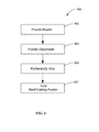
- FIG. 4 is a flow chart of method 400 of providing bond coating powder 210.
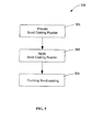
- FIG. 5 is a flow chart of method 500 of applying a bond coating 14 to a component 10 (see FIG. 1 ).
- bond coating powder 210 includes powder 90 including plurality of parent particles 100 and plurality of dispersoids 102 that are mechanically alloyed at ambient temperature. Mechanically alloying is operable to provide a selective occupation of plurality of dispersoids 102 in grain boundary area 104 of plurality of parent particles 100 providing bond coating powder 210.
- Method 500 include applying bond coating powder 210 to component 10 (see FIG. 1 ), step 503.
- Applying bond coating powder 210 is done using any suitable application method, such as but not limited to, thermal spraying processes including air plasma spraying, vacuum plasma spraying, high velocity oxy-fuel coating spraying (HVOF), warm spraying, and cold spraying processes.
- Method 500 includes forming bond coating 14 on component 10, see FIG. 1 , step 505. Bond coating 14 reduces the depletion rate of aluminum from bond coating 14 to adjacent bond coat and thermal barrier coating interface 20 and from bond coating 14 to adjacent bond coat and substrate 12 interface 22.
- the following assumptions have been made in calculating percentage of grain boundary area 104 occupied by dispersoids 102: (1) bond coat grains are generally 14-sided, truncated octahedra, which is the only space-filling shape that has all 3 grain boundaries meeting at a triple point at 120 degrees relative to each other, as required by the surface energy balance; (2) bond coat grain size is approximately 0.1 micron; (3) density of the bond coat alloy is approximately 8 g/cc; (4) spherical dispersoids 102 have a diameter of approximately 0.01 micron; (5) dispersoids 102 content is about 1 w% of bond coat 14; and (4) grain boundaries go through the center of dispersoids 102.
- the present disclosure provides that approximately 27% of grain boundary area 104 of parent particle 100 of bond coating powder 210 is occupied when dispersoid 102 is Al 2 O 3 .
- the present disclosure provides that approximately 25% of grain boundary area 104 of parent particle 100 of bond coating powder 210 occupied when dispersoid 102 is Y 2 O 3 .
- the present disclosure provides that approximately 18% of grain boundary area 104 of parent particle 100 of bond coating powder 210 is occupied when dispersoid 102 is ZrO 2 .
- the flux of atoms is proportional to the area normal to the flow direction. Aluminum will diffuse through the volume of the bond coat 14 by traversing the grains and crossing the boundaries whenever these boundaries are encountered. In the absence of any grain boundary dispersoids, the aluminum atoms can also travel along the boundaries of the bond coat, thereby allow the aluminum to diffuse of the bond coat and weaken the bond coat.
- there is little or no grain boundary diffusion of aluminum. This diffusion of aluminum is stopped by the plurality of dispersoids 102 in the grain boundaries 104 of the plurality of parent particles 100 (see FIG. 2 at Time T 2 >T1).
- the aluminum atoms When the aluminum atoms encounter a dispersoid while diffusing along grain boundary 104, the aluminum atoms will enter a grain and participate in volume diffusion.
- the lowest amount of reduction in diffusion will be for the case when D(gb) ⁇ D(v), such that the diffusion rate will be reduced by about 27 % when the dispersoids 102 are Al 2 O 3 . If D(gb) > D(v), the extent of reduction in diffusion rate of aluminum atoms will be even greater than 27 % when dispersoids 102 are Al 2 O 3 .
Landscapes
- Chemical & Material Sciences (AREA)
- Engineering & Computer Science (AREA)
- Materials Engineering (AREA)
- Mechanical Engineering (AREA)
- Metallurgy (AREA)
- Organic Chemistry (AREA)
- Chemical Kinetics & Catalysis (AREA)
- Physics & Mathematics (AREA)
- Plasma & Fusion (AREA)
- Turbine Rotor Nozzle Sealing (AREA)
- Application Of Or Painting With Fluid Materials (AREA)
Abstract
Description
- The present invention relates generally to coatings and more specifically to a bond coating powder and method of making the bond coating powder and method of applying the bond coating powder to components in gas turbines.
- Many of the cobalt and nickel based superalloy materials traditionally used to fabricate the majority of combustion turbine components used in the hot gas path section of the combustion turbine engine are insulated from the hot gas flow by coating the components with a thermal barrier coating (TBC) in order to survive long term operation in this aggressive high temperature combustion environment.
- TBC systems often consist of four layers: the metal substrate, a McrAlY (where M is Ni, Co or a combination thereof) bond coat, a thin thermally grown oxide (TGO) formed during service, and ceramic topcoat. The ceramic topcoat is typically composed of yttria-stabilized zirconia (YSZ), which is desirable for having very low thermal conductivity while remaining stable at nominal operating temperatures typically seen in applications. TBCs experience degradation through various degradation modes that include mechanical rumpling of bond coat during thermal cyclic exposure, accelerated oxidation of bond coat, hot corrosion, and molten deposit degradation. With the loss of the TBC, the component experiences much higher temperatures and the component life is reduced dramatically.
- Typical MCrAlY bond coats have a 2-phase structure of fine γ-(M) (face-center cubic) and β-(M)Al (body-center cubic). The β-(M)Al phase is the aluminum (Al) reservoir. Aluminum in the bond coat will be depleted during service by either diffusion to the bond coat/TBC interface forming α-Al2O3 TGO or into the substrate. Spallation of the TBC will occur when the TGO layer is very thick or there is no more aluminum from the bond coat to form the adherent α-Al2O3 scale. Aluminum diffusion and TGO growth depend on bond coat temperatures, i.e., higher bond coat temperatures will accelerate aluminum diffusion and TGO growth, and hence TBC spallation and reduce component service life.
- Therefore, bond coat temperatures are limited due to oxidation, spallation, and depletion of the aluminum reservoir in the bond coating. Some standard bond coatings, such as GT33 (available from Sulzer Metco, Westbury, New York) have operational temperature limits of about 1750°F. At temperature higher than the operational temperature limit, the bond coating will deteriorate much faster due to accelerated oxidation which increases the chances of spallation of the thermal barrier coating (TBC) applied to the bond coating and hence reduce the component service life.
- Therefore, a bond coating powder and method of making the bond coating powder and method of applying the bond coating powder to components in gas turbines that do not suffer from the above drawbacks is desirable in the art.
- Certain embodiments commensurate in scope with the originally claimed invention are summarized below. These embodiments are not intended to limit the scope of the claimed invention, but rather these embodiments are intended only to provide a brief summary of possible forms of the invention. Indeed, the invention may encompass a variety of forms that may be similar to or different from the embodiments set forth below.
- According to an exemplary embodiment of the present disclosure, a method of making a bond coating powder is provided. The method includes providing a powder including a plurality of parent particles. The method includes providing a plurality of dispersoids. The method includes mechanically alloying the powder and the plurality of dispersoids at ambient temperature. The mechanically alloying being operable to provide a selective occupation by the plurality of dispersoids in a grain boundary area of the plurality of parent particles of the bond coating powder. The plurality of dispersoids occupy about 18 percent to about 30 percent of the grain boundary area.
- According to another exemplary embodiment of the present disclosure, a bond coating powder is provided. The bond coating powder includes a plurality of parent particles having a plurality of dispersoids mechanically alloyed with the plurality of parent particles forming the bond coating powder. The plurality of dispersoids selectively occupy a grain boundary area of the plurality of parent particles of the bond coating powder. The plurality of dispersoids occupy from about 18 percent to about 30 percent of the grain boundary area.
- According to another exemplary embodiment of the present disclosure, a method of applying a bond coating to a component is provided. The method includes providing a bond coating powder including a plurality of parent particles. The method includes providing a plurality of dispersoids. The method includes mechanically alloying the powder and the plurality of dispersoids at ambient temperature, the mechanically alloying being operable to provide a selective occupation by the plurality of dispersoids in a grain boundary area of the plurality of particles of the bond coating powder. The plurality of dispersoids occupy about 18 percent to about 30 percent of the grain boundary area. The method includes applying the bond coating powder to the component wherein a bond coating forms on the metallic component, wherein the plurality of dispersoids occupying the grain boundary area of the bond coating reduces the depletion rate of aluminum from the bond coating to an adjacent bond coat and thermal barrier coating interface.
- Other features and advantages of the present invention will be apparent from the following more detailed description of the preferred embodiment, taken in conjunction with the accompanying drawings which illustrate, by way of example, the principles of the invention.
-
-
FIG. 1 is a sectional view of a component including a coating of the bond coating powder of the present disclosure. -
FIG. 2 is a time-lapsed schematic of a bond coating powder of the present disclosure. -
FIG. 3 is a schematic of a grain boundary in a single particle of the bond coating powder of the present disclosure. -
FIG. 4 is a flow chart a method of making a bond coating powder of the present disclosure. -
FIG. 5 is a flow chart of a method of applying a bond coating of the present disclosure. - Wherever possible, the same reference numbers will be used throughout the drawings to represent the same parts.
- Provided is an economically viable method of making a bond coating powder and method of applying the bond coating powder to components in gas turbines that do not suffer from the drawbacks in the prior art. One advantage of an embodiment of the present disclosure is that the bond coating powder and bond coating of the present disclosure provide heavily occupied grain boundaries. Another advantage of an embodiment of the present disclosure is that dispersoids occupying the grain boundaries of the bond coating inhibit volume and grain boundary diffusion of aluminum to the underlying superalloy component or to the bond coat/TBC interface thereby slowing alumina scale growth reducing spalling of the TBC from the bond coating. Yet another advantage of the present disclosure is a bond coating powder and bond coating that provides a slow formation of alumina in the bond coating. Another advantage of the present disclosure is that the bond coating powder and bond coating provide heavily occupied grain boundaries. Yet another advantage of the present disclosure is that the life of TBC of the present disclosure is greater than that of traditional TBC/bond coating systems.
- One or more specific embodiments of the present invention will be described below. In an effort to provide a concise description of these embodiments, all features of an actual implementation may not be described in the specification. It should be appreciated that in the development of any such actual implementation, as in any engineering or design project, numerous implementation-specific decisions must be made to achieve the developers' specific goals, such as compliance with system-related and business-related constraints, which may vary from one implementation to another. Moreover, it should be appreciated that such a development effort might be complex and time consuming, but would nevertheless be a routine undertaking of design, fabrication, and manufacture for those of ordinary skill having the benefit of this disclosure.
- When introducing elements of various embodiments of the present invention, the articles "a," "an," "the," and "said" are intended to mean that there are one or more of the elements. The terms "comprising," "including," and "having" are intended to be inclusive and mean that there may be additional elements other than the listed elements.
- Systems used to generate power include, but are not limited to, gas turbines, steam turbines, and other turbine assemblies. In certain applications, the power generation systems, including the turbomachinery therein (e.g., turbines, compressors, and pumps) and other machinery may include components that are exposed to heavy wear conditions. For example, certain power generation system components such as blades, casings, rotor wheels, shafts, shrouds, nozzles, and so forth, may operate in high heat and high revolution environments. Materials for components are manufactured from nickel based superalloys, cobalt based superalloys, chromium based superalloys, and combinations thereof and include a bond coating and thermal barrier coating (TBC) generally manufactured from ceramics. The present disclosure provides a durable and reliant bond coating between the base material and TBC of the gas turbine components.
-
FIG. 1 is a schematic of acomponent 10 including a substrate 12 having abond coating 14 and thermal barrier coating (TBC) 16 applied thereto.Component 10 can be any component of a power generation system such as, but not limited to, blades, casings, rotor wheels, shafts, shrouds, and nozzles. Substrate 12 ofcomponent 10 is generally selected from material that withstands high temperatures and harsh operating environments. Suitable examples of material for substrate 12 include, but are not limited to, erosion resistant materials including cobalt, chromium, tungsten, carbon, nickel, iron, silicon, molybdenum, manganese, alloys thereof and combinations thereof. Suitable examples of materials forTBC 16 include, but are not limited to, ceramics based on zirconium stabilized with an oxide or rare-earth oxide, such as yttrium oxide, magnesium oxide, or cerium oxide.Bond coating 14 is applied adjacent to or between substrate 12 andTBC 16 to provide a transition between the different coefficients of thermal expansion between the metallic material of substrate 12 and ceramic based material ofTBC 16.Bond coating 14 provides oxidation resistance to substrate 12 and a rough surface for mechanical bonding ofTBC 16 to substrate 12.Bond coating 14 includes bond coating powder 210 (seeFIG. 2 ).Bond coating 14 of the present disclosure reduces the depletion rate of aluminum frombond coating 14 to adjacent bond coat and thermalbarrier coating interface 20. Additionally,bond coating 14 reduces the depletion rate of aluminum frombond coating 14 to adjacent bond coat andsubstrate interface 22. -
FIG. 2 is a schematic time lapse at time zero, at the start of mechanically alloying, Time 1 (T1), during mechanically alloying, Time 2 (T2) and after mechanically alloying, Time 3 (T3) of the manufacturing ofbond coating powder 210 used to make bond coating 14 (seeFIG. 1 ). Bond coating powder 210 (at Time T3>T2) includes a plurality ofparent particles 100 having a plurality ofdispersoids 102 mechanically alloyed with plurality ofparent particles 100 forming resulting in a somewhat modifiedbond coating powder 210.Bond coating powder 210 is modified because it contains plurality of dispersoids occupyinggrain boundary 104 of parent particles 100 (seeFIG. 2 , Time 3). Mechanically alloying includes ball milling, high-energy ball milling, attritor milling, triaxial vibratory milling, and combinations thereof. Mechanical alloying is optionally conducted in an inert atmosphere, such as under argon, to minimize oxidation of active surfaces that are created when particles fracture during milling. Mechanical alloying is optionally performed at a reduced temperature to minimize excessive cold welding between particles. Mechanically alloying is conducted at ambient temperature of approximately 10°C to approximately 37.8°C (approximately 50°F to approximately 100°F). Mechanical alloying is conducted for a short period of time of approximately 2 hours to approximately 10 hours or alternatively approximately 3 hours to approximately 9 hours or alternatively approximately 4 hours to approximately 8 hours. - As shown in
FIG. 2 at time zero (Time = 0), prior to mechanically alloying, plurality ofparent particles 100 and plurality ofdispersoids 102 are separate and form apowder 90. At time zero (Time = 0) the size of theparent particles 100 and plurality of dispersoids is relatively the same. At the start of mechanically alloying, at Time = T1, plurality ofdispersoids 102 are beginning to occupygrain boundary 104 of plurality ofparent particles 100 and size of plurality ofdispersoids 102 is beginning to shrink. After T1 and before completing mechanical alloying at Time T2>T1, more ofgrain boundary 104 of plurality ofparent particles 100 is occupied by plurality of dispersoids 102. After mechanical allying at Time T3>T2 plurality ofdispersoids 102 selectively occupy from approximately 18 percent to approximately 30 percent ofgrain boundary area 104 of plurality ofparent particles 100 providingbond coating powder 210. Without being bound by theory, it is believed that mechanical alloying obtains sub-micron grain sizes and uniform distribution ofdispersoids 102 alonggrain boundaries 104 of plurality ofparent particles 100. It is also believed, without being bound by theory, that plurality ofdispersoids 102 occupyinggrain boundaries 104 limit volume and grain boundary diffusion and coarsening, thereby reducing the aluminum (Al) depletion rate and increased the TBC spallation life. -
FIG. 3 is a typical grain in a modifiedsingle particle 200 ofbond coating powder 210. Modifiedsingle particle 200 includes plurality ofdispersoids 102 occupying from approximately 18 percent to approximately 30 percent ofgrain boundary area 104 or alternatively approximately 22 percent to approximately 28 percent ofgrain boundary area 104 or alternatively approximately 23 percent to approximately 27 percent ofgrain boundary area 104 ofbond coating powder 210. - Plurality of
dispersoids 102 are selected from particles, such as, but not limited to, zirconium-oxide (ZrO2), aluminum-oxide (Al2O3), yttrium-oxide (Y2O3), magnesium-oxide (MgO), cerium-oxide (CeO), and combinations thereof. Particle size of plurality ofdispersoids 102 after mechanical alloying is from approximately 0.010 micron to approximately 0.020 microns or alternatively from approximately 0.010 microns to approximately 0.018 microns or alternatively from approximately 0.010 microns to approximately 0.015 microns. Plurality ofdispersoids 102 comprise from approximately 0.5% by weight to approximately 1% by weight or alternatively from approximately 0.5% by weight to approximately 0.9% by weight or alternatively approximately 0.5% by weight to approximately 0.8% by weight ofbond coating powder 210. Plurality ofdispersoids 102 have a hardness of greater than about 4 Mohs. -
FIG. 4 is a flow chart ofmethod 400 of providingbond coating powder 210.Method 400 includes providing apowder 90 including plurality ofparent particles 100,step 401, and providing a plurality of dispersoids 102 (seeFIG. 2 at Time =0),step 403.Method 400 includes mechanically alloyingpowder 90 and plurality ofdispersoids 102 at ambient temperature (seeFIG. 2 at Time = T1 and Time = T2>T1),step 405. Mechanical alloying is operable to provide a selective occupation of plurality ofdispersoids 102 ingrain boundary area 104 of plurality ofparent particles 100 providing bond coating powder 210 (seeFIG. 2 at Time = T3>T2),step 407. Plurality ofdispersoids 102 occupy about 18 percent to about 30 ofgrain boundary area 104 ofparent particles 100 of bond coating powder 210 (seeFIG. 2 at Time = T3>T2 andFIG. 3 ). -
FIG. 5 is a flow chart ofmethod 500 of applying abond coating 14 to a component 10 (seeFIG. 1 ).Method 500 includes providing bond coating powder 210 (seeFIG. 2 Time = T3>T2),step 501. As shown inFIGS. 2 and3 ,bond coating powder 210 includespowder 90 including plurality ofparent particles 100 and plurality ofdispersoids 102 that are mechanically alloyed at ambient temperature. Mechanically alloying is operable to provide a selective occupation of plurality ofdispersoids 102 ingrain boundary area 104 of plurality ofparent particles 100 providingbond coating powder 210.Method 500 include applyingbond coating powder 210 to component 10 (seeFIG. 1 ),step 503. Applyingbond coating powder 210 is done using any suitable application method, such as but not limited to, thermal spraying processes including air plasma spraying, vacuum plasma spraying, high velocity oxy-fuel coating spraying (HVOF), warm spraying, and cold spraying processes.Method 500 includes formingbond coating 14 oncomponent 10, seeFIG. 1 ,step 505.Bond coating 14 reduces the depletion rate of aluminum frombond coating 14 to adjacent bond coat and thermalbarrier coating interface 20 and frombond coating 14 to adjacent bond coat and substrate 12interface 22. - The following is an estimated calculation of the percentage
grain boundary area 104 occupied bydispersoids 102 inparent particles 100 after mechanically alloying at ambient temperature (seeFIG. 2 at Time = T2>T1). The following assumptions have been made in calculating percentage ofgrain boundary area 104 occupied by dispersoids 102: (1) bond coat grains are generally 14-sided, truncated octahedra, which is the only space-filling shape that has all 3 grain boundaries meeting at a triple point at 120 degrees relative to each other, as required by the surface energy balance; (2) bond coat grain size is approximately 0.1 micron; (3) density of the bond coat alloy is approximately 8 g/cc; (4)spherical dispersoids 102 have a diameter of approximately 0.01 micron; (5) dispersoids 102 content is about 1 w% ofbond coat 14; and (4) grain boundaries go through the center of dispersoids 102. - The present disclosure provides that approximately 27% of
grain boundary area 104 ofparent particle 100 ofbond coating powder 210 is occupied when dispersoid 102 is Al2O3. The present disclosure provides that approximately 25% ofgrain boundary area 104 ofparent particle 100 ofbond coating powder 210 occupied when dispersoid 102 is Y2O3. The present disclosure provides that approximately 18% ofgrain boundary area 104 ofparent particle 100 ofbond coating powder 210 is occupied when dispersoid 102 is ZrO2. Generally, it has been estimated thatlighter dispersoid 102 and higher dispersoid 102 content inparent particles 100, the higher percentage occupation ofgrain boundary area 104 inbond coating powder 210. - The following calculation was estimated for the reduction in the diffusion rate of the present disclosure. In the diffusion rate, the flux of atoms is proportional to the area normal to the flow direction. Aluminum will diffuse through the volume of the
bond coat 14 by traversing the grains and crossing the boundaries whenever these boundaries are encountered. In the absence of any grain boundary dispersoids, the aluminum atoms can also travel along the boundaries of the bond coat, thereby allow the aluminum to diffuse of the bond coat and weaken the bond coat. For unit area, the flux, expressed in arbitrary units, is given by the following equations:
where D(gb) is the diffusion coefficient for grain boundary; and D(v) is the is the diffusion coefficient for volume diffusion,
where f is the fraction of boundary area occupied; and D(v) is the is the diffusion coefficient for volume diffusion. In the present disclosure, there is little or no grain boundary diffusion of aluminum. This diffusion of aluminum is stopped by the plurality ofdispersoids 102 in thegrain boundaries 104 of the plurality of parent particles 100 (seeFIG. 2 at Time = T2>T1). When the aluminum atoms encounter a dispersoid while diffusing alonggrain boundary 104, the aluminum atoms will enter a grain and participate in volume diffusion. In the present disclosure, the lowest amount of reduction in diffusion will be for the case when D(gb) << D(v), such that the diffusion rate will be reduced by about 27 % when thedispersoids 102 are Al2O3. If D(gb) > D(v), the extent of reduction in diffusion rate of aluminum atoms will be even greater than 27 % when dispersoids 102 are Al2O3. - While the invention has been described with reference to a preferred embodiment, it will be understood by those skilled in the art that various changes may be made and equivalents may be substituted for elements thereof without departing from the scope of the invention. In addition, many modifications may be made to adapt a particular situation or material to the teachings of the invention without departing from the essential scope thereof. Therefore, it is intended that the invention not be limited to the particular embodiment disclosed as the best mode contemplated for carrying out this invention, but that the invention will include all embodiments falling within the scope of the appended claims.
Claims (15)
- A method (400) of making a bond coating powder (210) comprising:providing (401) a powder (90) including a plurality of parent particles (100);providing (403) a plurality of dispersoids (102); andmechanically alloying (405) the powder (90) and the plurality of dispersoids (102) at ambient temperature, the mechanical alloying (405) being operable to provide a selective occupation by the plurality of dispersoids (102) in a grain boundary area (104) of the plurality of parent particles (100) of the bond coating powder (210);wherein the plurality of dispersoids (102) occupy about 18 percent to about 30 percent of the grain boundary area (104).
- The method (400) of claim 1, wherein the plurality of dispersoids (102) are selected from the group consisting of zirconium-oxide (ZrO2), aluminum-oxide (Al2O3), yttrium-oxide (Y2O3), magnesium-oxide (MgO), cerium-oxide (CeO) and combinations thereof.
- The method (400) of claim 1 or claim 2, wherein the plurality of dispersoids (102) have a particle size from about 0.010 microns to about 0.020 microns after mechanically alloying.
- The method (400) of any preceding claim, wherein the plurality of dispersoids (102) comprise from about 0.5% by weight to about 1% by weight of the bond coating powder (210).
- The method (400) of any preceding claim, wherein the plurality of dispersoids (102) have a hardness of greater than about 4 Mohs.
- The method (400) of any preceding claim, wherein the powder (90) is selected from the group consisting of MCrAlY, wherein M is Ni, Fe, Co, and combinations thereof.
- The method (400) of any preceding claim, wherein the plurality of dispersoids (102) occupying the grain boundary area (104) hinders grain coarsening in a bond coat layer (14).
- The method (400) of any preceding claim, wherein the step of mechanically alloying (405) includes ball milling, high-energy ball milling, attritor milling, triaxial vibratory milling, and combinations thereof.
- A bond coating powder (210) comprising:a plurality of parent particles (100) having a plurality of dispersoids (102) mechanically alloyed with the plurality of parent particles (100) forming the bond coating powder (210), wherein the plurality of dispersoids (102) selectively occupy a grain boundary area (104) of the plurality of parent particles (100) providing a bond coating powder (210);wherein the plurality of dispersoids (102) occupy from about 18 percent to about 30 percent of the grain boundary area (104).
- The bond coating powder (210) of claim 9, wherein the plurality of dispersoids (102) are selected from the group consisting of zirconium-oxide (ZrO2), aluminium-oxide (Al2O3), yttrium-oxide (Y2O3), magnesium-oxide (MgO), cerium-oxide (CeO), and combinations thereof.
- The bond coating powder (210) of claim 9 or claim 10, wherein the plurality of dispersoids (102) have a particle size from about 0.010 microns to about 0.020 microns after mechanically alloying.
- The bond coating powder (210) of any one of claims 9 to 11, wherein the plurality of dispersoids (102) comprise from about 0.5% by weight to about 1% by weight of the bond coating powder (210).
- The bond coating powder (210) of any one of claims 9 to 12, wherein the plurality of dispersoids (102) have a hardness of greater than about 4 Mohs.
- A method (500) of applying a bond coating (14) to a component (10) comprising:providing (501) a bond coating powder (210) including a plurality of parent particles (100);providing a plurality of dispersoids (102);mechanically alloying the powder (90) and the plurality of dispersoids (102) at ambient temperature, the mechanically alloying being operable to provide a selective occupation by the plurality of dispersoids (102) in a grain boundary area (104) of the plurality of particles of the bond coating powder (210), the plurality of dispersoids (102) occupying about 18 percent to about 30 percent of the grain boundary area (104);applying (503) the bond coating powder (210) to the component (10), wherein a bond coating (14) forms on the metallic component (10), wherein the plurality of dispersoids (102) occupying the grain boundary area (104) of the bond coating (14) reduces the depletion rate of aluminum from the bond coating (14) to an adjacent bond coat and thermal barrier coating interface (20).
- The method (500) of claim 14, wherein the step of mechanically alloying includes ball milling, high-energy ball milling, attritor milling, triaxial vibratory milling, and combinations thereof.
Applications Claiming Priority (1)
| Application Number | Priority Date | Filing Date | Title |
|---|---|---|---|
| US13/366,048 US8999514B2 (en) | 2012-02-03 | 2012-02-03 | Bond coating powder comprising MCrAlY (M=Ni,Fe,Co), method of making, and a method of applying as bond coating |
Publications (3)
| Publication Number | Publication Date |
|---|---|
| EP2623234A2 true EP2623234A2 (en) | 2013-08-07 |
| EP2623234A3 EP2623234A3 (en) | 2017-02-01 |
| EP2623234B1 EP2623234B1 (en) | 2019-06-19 |
Family
ID=47713894
Family Applications (1)
| Application Number | Title | Priority Date | Filing Date |
|---|---|---|---|
| EP13153558.5A Active EP2623234B1 (en) | 2012-02-03 | 2013-01-31 | A bond coating powder, method of making, and a method of applying as bond coating |
Country Status (2)
| Country | Link |
|---|---|
| US (1) | US8999514B2 (en) |
| EP (1) | EP2623234B1 (en) |
Cited By (1)
| Publication number | Priority date | Publication date | Assignee | Title |
|---|---|---|---|---|
| CN111705252A (en) * | 2020-06-18 | 2020-09-25 | 西北工业大学 | A kind of Al2O3 nanoparticle reinforced CrCoNi medium entropy alloy matrix composite material and preparation method |
Families Citing this family (4)
| Publication number | Priority date | Publication date | Assignee | Title |
|---|---|---|---|---|
| JP6547209B2 (en) * | 2015-07-01 | 2019-07-24 | 国立大学法人東北大学 | Method of producing thermal barrier coating and powder for bond coat |
| US10731482B2 (en) | 2015-12-04 | 2020-08-04 | Raytheon Technologies Corporation | Enhanced adhesion thermal barrier coating |
| US20190316246A1 (en) | 2018-04-17 | 2019-10-17 | General Electric Company | Reactive phase spray formulation coatings |
| CN111299597A (en) * | 2020-03-26 | 2020-06-19 | 郑州大学 | A kind of preparation method of nanometer MgO particle reinforced magnesium matrix composite material |
Family Cites Families (13)
| Publication number | Priority date | Publication date | Assignee | Title |
|---|---|---|---|---|
| US3617358A (en) * | 1967-09-29 | 1971-11-02 | Metco Inc | Flame spray powder and process |
| US4101713A (en) * | 1977-01-14 | 1978-07-18 | General Electric Company | Flame spray oxidation and corrosion resistant superalloys |
| US5277936A (en) | 1987-11-19 | 1994-01-11 | United Technologies Corporation | Oxide containing MCrAlY-type overlay coatings |
| DE4208100C2 (en) | 1992-03-13 | 1994-05-26 | Mtu Muenchen Gmbh | Blank for the production of fiber-reinforced coatings or metal components |
| US5322666A (en) * | 1992-03-24 | 1994-06-21 | Inco Alloys International, Inc. | Mechanical alloying method of titanium-base metals by use of a tin process control agent |
| JP2796917B2 (en) * | 1993-02-02 | 1998-09-10 | 株式会社クボタ | Composite sintered alloy for non-ferrous metal melts with excellent corrosion resistance and wear resistance |
| US5879860A (en) * | 1993-12-08 | 1999-03-09 | Leica Microsystems Lithography Limited | Method of writing a pattern by an electron beam |
| US6277774B1 (en) * | 1997-08-22 | 2001-08-21 | Inframat Corporation | Grain growth inhibitor for superfine materials |
| CA2229124C (en) * | 1998-02-09 | 2001-08-14 | Pyrogenesis Inc. | Thermal barrier coating system having a top coat with a graded interface |
| US20030180571A1 (en) * | 1999-12-14 | 2003-09-25 | The Penn State Research Foundation | Microstructured coatings and materials |
| US20050133121A1 (en) * | 2003-12-22 | 2005-06-23 | General Electric Company | Metallic alloy nanocomposite for high-temperature structural components and methods of making |
| US20070151639A1 (en) * | 2006-01-03 | 2007-07-05 | Oruganti Ramkumar K | Nanostructured superalloy structural components and methods of making |
| US8449262B2 (en) * | 2009-12-08 | 2013-05-28 | Honeywell International Inc. | Nickel-based superalloys, turbine blades, and methods of improving or repairing turbine engine components |
-
2012
- 2012-02-03 US US13/366,048 patent/US8999514B2/en active Active
-
2013
- 2013-01-31 EP EP13153558.5A patent/EP2623234B1/en active Active
Non-Patent Citations (1)
| Title |
|---|
| None |
Cited By (1)
| Publication number | Priority date | Publication date | Assignee | Title |
|---|---|---|---|---|
| CN111705252A (en) * | 2020-06-18 | 2020-09-25 | 西北工业大学 | A kind of Al2O3 nanoparticle reinforced CrCoNi medium entropy alloy matrix composite material and preparation method |
Also Published As
| Publication number | Publication date |
|---|---|
| US8999514B2 (en) | 2015-04-07 |
| EP2623234B1 (en) | 2019-06-19 |
| EP2623234A3 (en) | 2017-02-01 |
| US20130202792A1 (en) | 2013-08-08 |
Similar Documents
| Publication | Publication Date | Title |
|---|---|---|
| Lee et al. | Concept of functionally graded materials for advanced thermal barrier coating applications | |
| US5780110A (en) | Method for manufacturing thermal barrier coated articles | |
| EP2521802B1 (en) | Coating system for clearance control in rotating machinery | |
| EP0909831B1 (en) | Process for depositing a bond coat for a thermal barrier coating system | |
| EP1640477B1 (en) | High temperature component with thermal barrier coating and gas turbine using the same | |
| US7326470B2 (en) | Thin 7YSZ, interfacial layer as cyclic durability (spallation) life enhancement for low conductivity TBCs | |
| EP2185742B1 (en) | Combustion turbine component having rare earth-containing coating and associated methods | |
| US20160333455A1 (en) | Thermal Barrier Coating with Lower Thermal Conductivity | |
| EP0979881A1 (en) | Thermal barrier and overlay coating systems comprising composite metal/metal oxide bond coating layers | |
| US9017792B2 (en) | Tri-barrier ceramic coating | |
| EP2108715A2 (en) | Thermal barrier coating system and coating methods for gas turbine engine shroud | |
| JP7232295B2 (en) | Adhesion-promoting layer for bonding high-temperature protective layer onto substrate, and method for producing same | |
| EP2191031B1 (en) | COMBUSTION TURBINE COMPONENT HAVING RARE EARTH NiCoCrAl COATING AND ASSOCIATED METHODS | |
| Zakeri et al. | Study on production of modified MCrAlY powder with nano oxide dispersoids as HVOF thermal spray feedstock using mechanical milling | |
| CN101133188A (en) | Substrates and Layering Systems | |
| CN101793195B (en) | Method and system for enhancing the heat transfer of turbine engine components | |
| EP1076727A1 (en) | Multilayer bond coat for a thermal barrier coating system and process therefor | |
| US8999514B2 (en) | Bond coating powder comprising MCrAlY (M=Ni,Fe,Co), method of making, and a method of applying as bond coating | |
| CN101522949B (en) | Pyrochlore materials and a thermal barrier coating with these pyrochlore materials | |
| US9139896B2 (en) | Heat-insulating protective layer for a component located within the hot gas zone of a gas turbine | |
| EP2690197A1 (en) | Turbine blade for industrial gas turbine and industrial gas turbine | |
| EP2636763A1 (en) | Method for applying a high-temperature stable coating layer on the surface of a component and component with such a coating layer | |
| EP2185741B1 (en) | Combustion turbine component having rare earth nicrai coating and associated methods | |
| WO2012029540A1 (en) | Heat-masking coating film, process for production thereof, and heat-resistant alloy members using the same | |
| JP2007239101A (en) | Bond coating method for thermal barrier coating |
Legal Events
| Date | Code | Title | Description |
|---|---|---|---|
| PUAI | Public reference made under article 153(3) epc to a published international application that has entered the european phase |
Free format text: ORIGINAL CODE: 0009012 |
|
| AK | Designated contracting states |
Kind code of ref document: A2 Designated state(s): AL AT BE BG CH CY CZ DE DK EE ES FI FR GB GR HR HU IE IS IT LI LT LU LV MC MK MT NL NO PL PT RO RS SE SI SK SM TR |
|
| AX | Request for extension of the european patent |
Extension state: BA ME |
|
| PUAL | Search report despatched |
Free format text: ORIGINAL CODE: 0009013 |
|
| AK | Designated contracting states |
Kind code of ref document: A3 Designated state(s): AL AT BE BG CH CY CZ DE DK EE ES FI FR GB GR HR HU IE IS IT LI LT LU LV MC MK MT NL NO PL PT RO RS SE SI SK SM TR |
|
| AX | Request for extension of the european patent |
Extension state: BA ME |
|
| RIC1 | Information provided on ipc code assigned before grant |
Ipc: C22C 1/10 20060101ALI20161223BHEP Ipc: B22F 9/04 20060101ALI20161223BHEP Ipc: B22F 5/04 20060101ALI20161223BHEP Ipc: B22F 1/02 20060101AFI20161223BHEP Ipc: C23C 24/04 20060101ALI20161223BHEP Ipc: C22C 33/02 20060101ALI20161223BHEP Ipc: C22C 32/00 20060101ALI20161223BHEP |
|
| STAA | Information on the status of an ep patent application or granted ep patent |
Free format text: STATUS: REQUEST FOR EXAMINATION WAS MADE |
|
| 17P | Request for examination filed |
Effective date: 20170801 |
|
| RBV | Designated contracting states (corrected) |
Designated state(s): AL AT BE BG CH CY CZ DE DK EE ES FI FR GB GR HR HU IE IS IT LI LT LU LV MC MK MT NL NO PL PT RO RS SE SI SK SM TR |
|
| GRAP | Despatch of communication of intention to grant a patent |
Free format text: ORIGINAL CODE: EPIDOSNIGR1 |
|
| STAA | Information on the status of an ep patent application or granted ep patent |
Free format text: STATUS: GRANT OF PATENT IS INTENDED |
|
| INTG | Intention to grant announced |
Effective date: 20190108 |
|
| RIC1 | Information provided on ipc code assigned before grant |
Ipc: B22F 1/02 20060101AFI20181217BHEP Ipc: C22C 33/02 20060101ALI20181217BHEP Ipc: C23C 4/067 20160101ALI20181217BHEP Ipc: B22F 9/04 20060101ALI20181217BHEP Ipc: C22C 32/00 20060101ALI20181217BHEP Ipc: C23C 24/04 20060101ALI20181217BHEP Ipc: C22C 1/10 20060101ALI20181217BHEP Ipc: C23C 4/073 20160101ALI20181217BHEP Ipc: B22F 5/04 20060101ALN20181217BHEP |
|
| GRAS | Grant fee paid |
Free format text: ORIGINAL CODE: EPIDOSNIGR3 |
|
| GRAA | (expected) grant |
Free format text: ORIGINAL CODE: 0009210 |
|
| STAA | Information on the status of an ep patent application or granted ep patent |
Free format text: STATUS: THE PATENT HAS BEEN GRANTED |
|
| AK | Designated contracting states |
Kind code of ref document: B1 Designated state(s): AL AT BE BG CH CY CZ DE DK EE ES FI FR GB GR HR HU IE IS IT LI LT LU LV MC MK MT NL NO PL PT RO RS SE SI SK SM TR |
|
| REG | Reference to a national code |
Ref country code: GB Ref legal event code: FG4D |
|
| REG | Reference to a national code |
Ref country code: CH Ref legal event code: EP |
|
| REG | Reference to a national code |
Ref country code: IE Ref legal event code: FG4D |
|
| REG | Reference to a national code |
Ref country code: DE Ref legal event code: R096 Ref document number: 602013056707 Country of ref document: DE |
|
| REG | Reference to a national code |
Ref country code: AT Ref legal event code: REF Ref document number: 1144845 Country of ref document: AT Kind code of ref document: T Effective date: 20190715 |
|
| REG | Reference to a national code |
Ref country code: NL Ref legal event code: MP Effective date: 20190619 |
|
| PG25 | Lapsed in a contracting state [announced via postgrant information from national office to epo] |
Ref country code: LT Free format text: LAPSE BECAUSE OF FAILURE TO SUBMIT A TRANSLATION OF THE DESCRIPTION OR TO PAY THE FEE WITHIN THE PRESCRIBED TIME-LIMIT Effective date: 20190619 Ref country code: SE Free format text: LAPSE BECAUSE OF FAILURE TO SUBMIT A TRANSLATION OF THE DESCRIPTION OR TO PAY THE FEE WITHIN THE PRESCRIBED TIME-LIMIT Effective date: 20190619 Ref country code: AL Free format text: LAPSE BECAUSE OF FAILURE TO SUBMIT A TRANSLATION OF THE DESCRIPTION OR TO PAY THE FEE WITHIN THE PRESCRIBED TIME-LIMIT Effective date: 20190619 Ref country code: FI Free format text: LAPSE BECAUSE OF FAILURE TO SUBMIT A TRANSLATION OF THE DESCRIPTION OR TO PAY THE FEE WITHIN THE PRESCRIBED TIME-LIMIT Effective date: 20190619 Ref country code: NO Free format text: LAPSE BECAUSE OF FAILURE TO SUBMIT A TRANSLATION OF THE DESCRIPTION OR TO PAY THE FEE WITHIN THE PRESCRIBED TIME-LIMIT Effective date: 20190919 Ref country code: HR Free format text: LAPSE BECAUSE OF FAILURE TO SUBMIT A TRANSLATION OF THE DESCRIPTION OR TO PAY THE FEE WITHIN THE PRESCRIBED TIME-LIMIT Effective date: 20190619 |
|
| REG | Reference to a national code |
Ref country code: LT Ref legal event code: MG4D |
|
| PG25 | Lapsed in a contracting state [announced via postgrant information from national office to epo] |
Ref country code: BG Free format text: LAPSE BECAUSE OF FAILURE TO SUBMIT A TRANSLATION OF THE DESCRIPTION OR TO PAY THE FEE WITHIN THE PRESCRIBED TIME-LIMIT Effective date: 20190919 Ref country code: GR Free format text: LAPSE BECAUSE OF FAILURE TO SUBMIT A TRANSLATION OF THE DESCRIPTION OR TO PAY THE FEE WITHIN THE PRESCRIBED TIME-LIMIT Effective date: 20190920 Ref country code: RS Free format text: LAPSE BECAUSE OF FAILURE TO SUBMIT A TRANSLATION OF THE DESCRIPTION OR TO PAY THE FEE WITHIN THE PRESCRIBED TIME-LIMIT Effective date: 20190619 Ref country code: LV Free format text: LAPSE BECAUSE OF FAILURE TO SUBMIT A TRANSLATION OF THE DESCRIPTION OR TO PAY THE FEE WITHIN THE PRESCRIBED TIME-LIMIT Effective date: 20190619 |
|
| REG | Reference to a national code |
Ref country code: AT Ref legal event code: MK05 Ref document number: 1144845 Country of ref document: AT Kind code of ref document: T Effective date: 20190619 |
|
| PG25 | Lapsed in a contracting state [announced via postgrant information from national office to epo] |
Ref country code: EE Free format text: LAPSE BECAUSE OF FAILURE TO SUBMIT A TRANSLATION OF THE DESCRIPTION OR TO PAY THE FEE WITHIN THE PRESCRIBED TIME-LIMIT Effective date: 20190619 Ref country code: AT Free format text: LAPSE BECAUSE OF FAILURE TO SUBMIT A TRANSLATION OF THE DESCRIPTION OR TO PAY THE FEE WITHIN THE PRESCRIBED TIME-LIMIT Effective date: 20190619 Ref country code: NL Free format text: LAPSE BECAUSE OF FAILURE TO SUBMIT A TRANSLATION OF THE DESCRIPTION OR TO PAY THE FEE WITHIN THE PRESCRIBED TIME-LIMIT Effective date: 20190619 Ref country code: PT Free format text: LAPSE BECAUSE OF FAILURE TO SUBMIT A TRANSLATION OF THE DESCRIPTION OR TO PAY THE FEE WITHIN THE PRESCRIBED TIME-LIMIT Effective date: 20191021 Ref country code: RO Free format text: LAPSE BECAUSE OF FAILURE TO SUBMIT A TRANSLATION OF THE DESCRIPTION OR TO PAY THE FEE WITHIN THE PRESCRIBED TIME-LIMIT Effective date: 20190619 Ref country code: CZ Free format text: LAPSE BECAUSE OF FAILURE TO SUBMIT A TRANSLATION OF THE DESCRIPTION OR TO PAY THE FEE WITHIN THE PRESCRIBED TIME-LIMIT Effective date: 20190619 Ref country code: SK Free format text: LAPSE BECAUSE OF FAILURE TO SUBMIT A TRANSLATION OF THE DESCRIPTION OR TO PAY THE FEE WITHIN THE PRESCRIBED TIME-LIMIT Effective date: 20190619 |
|
| PG25 | Lapsed in a contracting state [announced via postgrant information from national office to epo] |
Ref country code: IS Free format text: LAPSE BECAUSE OF FAILURE TO SUBMIT A TRANSLATION OF THE DESCRIPTION OR TO PAY THE FEE WITHIN THE PRESCRIBED TIME-LIMIT Effective date: 20191019 Ref country code: SM Free format text: LAPSE BECAUSE OF FAILURE TO SUBMIT A TRANSLATION OF THE DESCRIPTION OR TO PAY THE FEE WITHIN THE PRESCRIBED TIME-LIMIT Effective date: 20190619 Ref country code: ES Free format text: LAPSE BECAUSE OF FAILURE TO SUBMIT A TRANSLATION OF THE DESCRIPTION OR TO PAY THE FEE WITHIN THE PRESCRIBED TIME-LIMIT Effective date: 20190619 |
|
| PG25 | Lapsed in a contracting state [announced via postgrant information from national office to epo] |
Ref country code: TR Free format text: LAPSE BECAUSE OF FAILURE TO SUBMIT A TRANSLATION OF THE DESCRIPTION OR TO PAY THE FEE WITHIN THE PRESCRIBED TIME-LIMIT Effective date: 20190619 |
|
| PG25 | Lapsed in a contracting state [announced via postgrant information from national office to epo] |
Ref country code: DK Free format text: LAPSE BECAUSE OF FAILURE TO SUBMIT A TRANSLATION OF THE DESCRIPTION OR TO PAY THE FEE WITHIN THE PRESCRIBED TIME-LIMIT Effective date: 20190619 Ref country code: PL Free format text: LAPSE BECAUSE OF FAILURE TO SUBMIT A TRANSLATION OF THE DESCRIPTION OR TO PAY THE FEE WITHIN THE PRESCRIBED TIME-LIMIT Effective date: 20190619 |
|
| PG25 | Lapsed in a contracting state [announced via postgrant information from national office to epo] |
Ref country code: IS Free format text: LAPSE BECAUSE OF FAILURE TO SUBMIT A TRANSLATION OF THE DESCRIPTION OR TO PAY THE FEE WITHIN THE PRESCRIBED TIME-LIMIT Effective date: 20200224 |
|
| REG | Reference to a national code |
Ref country code: DE Ref legal event code: R097 Ref document number: 602013056707 Country of ref document: DE |
|
| PLBE | No opposition filed within time limit |
Free format text: ORIGINAL CODE: 0009261 |
|
| STAA | Information on the status of an ep patent application or granted ep patent |
Free format text: STATUS: NO OPPOSITION FILED WITHIN TIME LIMIT |
|
| PG2D | Information on lapse in contracting state deleted |
Ref country code: IS |
|
| 26N | No opposition filed |
Effective date: 20200603 |
|
| PG25 | Lapsed in a contracting state [announced via postgrant information from national office to epo] |
Ref country code: SI Free format text: LAPSE BECAUSE OF FAILURE TO SUBMIT A TRANSLATION OF THE DESCRIPTION OR TO PAY THE FEE WITHIN THE PRESCRIBED TIME-LIMIT Effective date: 20190619 Ref country code: MC Free format text: LAPSE BECAUSE OF FAILURE TO SUBMIT A TRANSLATION OF THE DESCRIPTION OR TO PAY THE FEE WITHIN THE PRESCRIBED TIME-LIMIT Effective date: 20190619 |
|
| REG | Reference to a national code |
Ref country code: BE Ref legal event code: MM Effective date: 20200131 |
|
| PG25 | Lapsed in a contracting state [announced via postgrant information from national office to epo] |
Ref country code: LU Free format text: LAPSE BECAUSE OF NON-PAYMENT OF DUE FEES Effective date: 20200131 Ref country code: FR Free format text: LAPSE BECAUSE OF NON-PAYMENT OF DUE FEES Effective date: 20200131 |
|
| PG25 | Lapsed in a contracting state [announced via postgrant information from national office to epo] |
Ref country code: BE Free format text: LAPSE BECAUSE OF NON-PAYMENT OF DUE FEES Effective date: 20200131 |
|
| PG25 | Lapsed in a contracting state [announced via postgrant information from national office to epo] |
Ref country code: IE Free format text: LAPSE BECAUSE OF NON-PAYMENT OF DUE FEES Effective date: 20200131 |
|
| REG | Reference to a national code |
Ref country code: DE Ref legal event code: R079 Ref document number: 602013056707 Country of ref document: DE Free format text: PREVIOUS MAIN CLASS: B22F0001020000 Ipc: B22F0001000000 |
|
| PG25 | Lapsed in a contracting state [announced via postgrant information from national office to epo] |
Ref country code: MT Free format text: LAPSE BECAUSE OF FAILURE TO SUBMIT A TRANSLATION OF THE DESCRIPTION OR TO PAY THE FEE WITHIN THE PRESCRIBED TIME-LIMIT Effective date: 20190619 Ref country code: CY Free format text: LAPSE BECAUSE OF FAILURE TO SUBMIT A TRANSLATION OF THE DESCRIPTION OR TO PAY THE FEE WITHIN THE PRESCRIBED TIME-LIMIT Effective date: 20190619 |
|
| PGFP | Annual fee paid to national office [announced via postgrant information from national office to epo] |
Ref country code: IT Payment date: 20220103 Year of fee payment: 10 |
|
| PG25 | Lapsed in a contracting state [announced via postgrant information from national office to epo] |
Ref country code: MK Free format text: LAPSE BECAUSE OF FAILURE TO SUBMIT A TRANSLATION OF THE DESCRIPTION OR TO PAY THE FEE WITHIN THE PRESCRIBED TIME-LIMIT Effective date: 20190619 |
|
| REG | Reference to a national code |
Ref country code: DE Ref legal event code: R082 Ref document number: 602013056707 Country of ref document: DE Ref country code: DE Ref legal event code: R081 Ref document number: 602013056707 Country of ref document: DE Owner name: GENERAL ELECTRIC TECHNOLOGY GMBH, CH Free format text: FORMER OWNER: GENERAL ELECTRIC COMPANY, SCHENECTADY, NY, US |
|
| PG25 | Lapsed in a contracting state [announced via postgrant information from national office to epo] |
Ref country code: IT Free format text: LAPSE BECAUSE OF NON-PAYMENT OF DUE FEES Effective date: 20230131 |
|
| REG | Reference to a national code |
Ref country code: GB Ref legal event code: 732E Free format text: REGISTERED BETWEEN 20240222 AND 20240228 |
|
| PGFP | Annual fee paid to national office [announced via postgrant information from national office to epo] |
Ref country code: GB Payment date: 20251217 Year of fee payment: 14 |
|
| REG | Reference to a national code |
Ref country code: CH Ref legal event code: U11 Free format text: ST27 STATUS EVENT CODE: U-0-0-U10-U11 (AS PROVIDED BY THE NATIONAL OFFICE) Effective date: 20260201 |
|
| PGFP | Annual fee paid to national office [announced via postgrant information from national office to epo] |
Ref country code: DE Payment date: 20251217 Year of fee payment: 14 |
|
| PGFP | Annual fee paid to national office [announced via postgrant information from national office to epo] |
Ref country code: CH Payment date: 20260201 Year of fee payment: 14 |