EP2623005A1 - Device for producing and method for producing wet wipes - Google Patents
Device for producing and method for producing wet wipes Download PDFInfo
- Publication number
- EP2623005A1 EP2623005A1 EP11828839.8A EP11828839A EP2623005A1 EP 2623005 A1 EP2623005 A1 EP 2623005A1 EP 11828839 A EP11828839 A EP 11828839A EP 2623005 A1 EP2623005 A1 EP 2623005A1
- Authority
- EP
- European Patent Office
- Prior art keywords
- sheets
- conveyance
- laminated body
- predetermined chemical
- predetermined
- Prior art date
- Legal status (The legal status is an assumption and is not a legal conclusion. Google has not performed a legal analysis and makes no representation as to the accuracy of the status listed.)
- Withdrawn
Links
Images



Classifications
-
- B—PERFORMING OPERATIONS; TRANSPORTING
- B65—CONVEYING; PACKING; STORING; HANDLING THIN OR FILAMENTARY MATERIAL
- B65H—HANDLING THIN OR FILAMENTARY MATERIAL, e.g. SHEETS, WEBS, CABLES
- B65H31/00—Pile receivers
- B65H31/30—Arrangements for removing completed piles
- B65H31/3027—Arrangements for removing completed piles by the nip between moving belts or rollers
-
- A—HUMAN NECESSITIES
- A47—FURNITURE; DOMESTIC ARTICLES OR APPLIANCES; COFFEE MILLS; SPICE MILLS; SUCTION CLEANERS IN GENERAL
- A47L—DOMESTIC WASHING OR CLEANING; SUCTION CLEANERS IN GENERAL
- A47L13/00—Implements for cleaning floors, carpets, furniture, walls, or wall coverings
- A47L13/10—Scrubbing; Scouring; Cleaning; Polishing
- A47L13/16—Cloths; Pads; Sponges
- A47L13/17—Cloths; Pads; Sponges containing cleaning agents
-
- B—PERFORMING OPERATIONS; TRANSPORTING
- B65—CONVEYING; PACKING; STORING; HANDLING THIN OR FILAMENTARY MATERIAL
- B65H—HANDLING THIN OR FILAMENTARY MATERIAL, e.g. SHEETS, WEBS, CABLES
- B65H29/00—Delivering or advancing articles from machines; Advancing articles to or into piles
- B65H29/24—Delivering or advancing articles from machines; Advancing articles to or into piles by air blast or suction apparatus
- B65H29/241—Suction devices
- B65H29/242—Suction bands or belts
-
- B—PERFORMING OPERATIONS; TRANSPORTING
- B65—CONVEYING; PACKING; STORING; HANDLING THIN OR FILAMENTARY MATERIAL
- B65H—HANDLING THIN OR FILAMENTARY MATERIAL, e.g. SHEETS, WEBS, CABLES
- B65H29/00—Delivering or advancing articles from machines; Advancing articles to or into piles
- B65H29/26—Delivering or advancing articles from machines; Advancing articles to or into piles by dropping the articles
- B65H29/32—Delivering or advancing articles from machines; Advancing articles to or into piles by dropping the articles from pneumatic, e.g. suction, carriers
-
- B—PERFORMING OPERATIONS; TRANSPORTING
- B65—CONVEYING; PACKING; STORING; HANDLING THIN OR FILAMENTARY MATERIAL
- B65H—HANDLING THIN OR FILAMENTARY MATERIAL, e.g. SHEETS, WEBS, CABLES
- B65H31/00—Pile receivers
- B65H31/04—Pile receivers with movable end support arranged to recede as pile accumulates
- B65H31/08—Pile receivers with movable end support arranged to recede as pile accumulates the articles being piled one above another
- B65H31/10—Pile receivers with movable end support arranged to recede as pile accumulates the articles being piled one above another and applied at the top of the pile
-
- B—PERFORMING OPERATIONS; TRANSPORTING
- B65—CONVEYING; PACKING; STORING; HANDLING THIN OR FILAMENTARY MATERIAL
- B65H—HANDLING THIN OR FILAMENTARY MATERIAL, e.g. SHEETS, WEBS, CABLES
- B65H31/00—Pile receivers
- B65H31/30—Arrangements for removing completed piles
- B65H31/3054—Arrangements for removing completed piles by moving the surface supporting the lowermost article of the pile, e.g. by using belts or rollers
-
- B—PERFORMING OPERATIONS; TRANSPORTING
- B65—CONVEYING; PACKING; STORING; HANDLING THIN OR FILAMENTARY MATERIAL
- B65H—HANDLING THIN OR FILAMENTARY MATERIAL, e.g. SHEETS, WEBS, CABLES
- B65H35/00—Delivering articles from cutting or line-perforating machines; Article or web delivery apparatus incorporating cutting or line-perforating devices, e.g. adhesive tape dispensers
- B65H35/04—Delivering articles from cutting or line-perforating machines; Article or web delivery apparatus incorporating cutting or line-perforating devices, e.g. adhesive tape dispensers from or with transverse cutters or perforators
- B65H35/08—Delivering articles from cutting or line-perforating machines; Article or web delivery apparatus incorporating cutting or line-perforating devices, e.g. adhesive tape dispensers from or with transverse cutters or perforators from or with revolving, e.g. cylinder, cutters or perforators
-
- B—PERFORMING OPERATIONS; TRANSPORTING
- B65—CONVEYING; PACKING; STORING; HANDLING THIN OR FILAMENTARY MATERIAL
- B65H—HANDLING THIN OR FILAMENTARY MATERIAL, e.g. SHEETS, WEBS, CABLES
- B65H39/00—Associating, collating, or gathering articles or webs
- B65H39/10—Associating articles from a single source, to form, e.g. a writing-pad
-
- B—PERFORMING OPERATIONS; TRANSPORTING
- B65—CONVEYING; PACKING; STORING; HANDLING THIN OR FILAMENTARY MATERIAL
- B65H—HANDLING THIN OR FILAMENTARY MATERIAL, e.g. SHEETS, WEBS, CABLES
- B65H45/00—Folding thin material
- B65H45/02—Folding limp material without application of pressure to define or form crease lines
- B65H45/06—Folding webs
- B65H45/08—Folding webs longitudinally
-
- B—PERFORMING OPERATIONS; TRANSPORTING
- B65—CONVEYING; PACKING; STORING; HANDLING THIN OR FILAMENTARY MATERIAL
- B65H—HANDLING THIN OR FILAMENTARY MATERIAL, e.g. SHEETS, WEBS, CABLES
- B65H2301/00—Handling processes for sheets or webs
- B65H2301/40—Type of handling process
- B65H2301/42—Piling, depiling, handling piles
- B65H2301/421—Forming a pile
- B65H2301/4213—Forming a pile of a limited number of articles, e.g. buffering, forming bundles
-
- B—PERFORMING OPERATIONS; TRANSPORTING
- B65—CONVEYING; PACKING; STORING; HANDLING THIN OR FILAMENTARY MATERIAL
- B65H—HANDLING THIN OR FILAMENTARY MATERIAL, e.g. SHEETS, WEBS, CABLES
- B65H2301/00—Handling processes for sheets or webs
- B65H2301/50—Auxiliary process performed during handling process
- B65H2301/51—Modifying a characteristic of handled material
- B65H2301/514—Modifying physical properties
- B65H2301/5142—Moistening
-
- B—PERFORMING OPERATIONS; TRANSPORTING
- B65—CONVEYING; PACKING; STORING; HANDLING THIN OR FILAMENTARY MATERIAL
- B65H—HANDLING THIN OR FILAMENTARY MATERIAL, e.g. SHEETS, WEBS, CABLES
- B65H2404/00—Parts for transporting or guiding the handled material
- B65H2404/20—Belts
- B65H2404/26—Particular arrangement of belt, or belts
- B65H2404/261—Arrangement of belts, or belt(s) / roller(s) facing each other for forming a transport nip
-
- B—PERFORMING OPERATIONS; TRANSPORTING
- B65—CONVEYING; PACKING; STORING; HANDLING THIN OR FILAMENTARY MATERIAL
- B65H—HANDLING THIN OR FILAMENTARY MATERIAL, e.g. SHEETS, WEBS, CABLES
- B65H2404/00—Parts for transporting or guiding the handled material
- B65H2404/20—Belts
- B65H2404/26—Particular arrangement of belt, or belts
- B65H2404/264—Arrangement of side-by-side belts
-
- B—PERFORMING OPERATIONS; TRANSPORTING
- B65—CONVEYING; PACKING; STORING; HANDLING THIN OR FILAMENTARY MATERIAL
- B65H—HANDLING THIN OR FILAMENTARY MATERIAL, e.g. SHEETS, WEBS, CABLES
- B65H2404/00—Parts for transporting or guiding the handled material
- B65H2404/60—Other elements in face contact with handled material
- B65H2404/64—Other elements in face contact with handled material reciprocating perpendicularly to face of material, e.g. pushing means
-
- B—PERFORMING OPERATIONS; TRANSPORTING
- B65—CONVEYING; PACKING; STORING; HANDLING THIN OR FILAMENTARY MATERIAL
- B65H—HANDLING THIN OR FILAMENTARY MATERIAL, e.g. SHEETS, WEBS, CABLES
- B65H2406/00—Means using fluid
- B65H2406/30—Suction means
- B65H2406/32—Suction belts
- B65H2406/323—Overhead suction belt, i.e. holding material against gravity
-
- B—PERFORMING OPERATIONS; TRANSPORTING
- B65—CONVEYING; PACKING; STORING; HANDLING THIN OR FILAMENTARY MATERIAL
- B65H—HANDLING THIN OR FILAMENTARY MATERIAL, e.g. SHEETS, WEBS, CABLES
- B65H2701/00—Handled material; Storage means
- B65H2701/10—Handled articles or webs
- B65H2701/18—Form of handled article or web
- B65H2701/182—Piled package
- B65H2701/18271—Piled package of folded sheet material
- B65H2701/18272—Z-folded
-
- B—PERFORMING OPERATIONS; TRANSPORTING
- B65—CONVEYING; PACKING; STORING; HANDLING THIN OR FILAMENTARY MATERIAL
- B65H—HANDLING THIN OR FILAMENTARY MATERIAL, e.g. SHEETS, WEBS, CABLES
- B65H2701/00—Handled material; Storage means
- B65H2701/10—Handled articles or webs
- B65H2701/18—Form of handled article or web
- B65H2701/182—Piled package
- B65H2701/1828—Parts concerned of piled package
- B65H2701/18282—Sides
-
- B—PERFORMING OPERATIONS; TRANSPORTING
- B65—CONVEYING; PACKING; STORING; HANDLING THIN OR FILAMENTARY MATERIAL
- B65H—HANDLING THIN OR FILAMENTARY MATERIAL, e.g. SHEETS, WEBS, CABLES
- B65H2701/00—Handled material; Storage means
- B65H2701/10—Handled articles or webs
- B65H2701/19—Specific article or web
- B65H2701/1924—Napkins or tissues, e.g. dressings, toweling, serviettes, kitchen paper and compresses
Definitions
- the present invention relates to a method and an apparatus for manufacturing wet wipes.
- Patent Literatures 1 and 2 As a method for manufacturing wet wipes formed of a laminated body of sheets impregnated with a predetermined chemical, there are known methods disclosed in Patent Literatures 1 and 2.
- a method disclosed in Patent Literature 1 has: a step of impregnating an original fabric with part of a predetermined chemical during conveyance of the original fabric before lamination; a step of squeezing out an excess of the predetermined chemical impregnated in the original fabric during conveyance of the original fabric; a step of laminating a plurality of original fabrics during conveyance of the original fabrics; and a step of impregnating the original fabrics with the rest of the predetermined chemical during conveyance of the original fabrics after lamination.
- a method disclosed in Patent Literature 2 has: a step of impregnating an original fabric with a predetermined chemical during conveyance of the original fabric before lamination; a step of laminating the original fabric while folding it back during conveyance of the original fabric; a step of conveying the original fabric after lamination while compressing it in a thickness direction and thereafter cutting the original fabric; and the like.
- Patent Literatures 1 and 2 have a configuration of a so-called pop-up type that when one sheet is taken out of a container, the next one is also pulled out together and protruded from an outlet of the container.
- the pop-up type wet wipes described above have a problem that if an impregnation rate of a predetermined chemical to an original fabric is increased, the original fabrics are interconnected by means of a water screen of the predetermined chemical, which makes it difficult to take sheets out of the container one by one, so that the impregnation rate of the predetermined chemical to the original fabric has to be kept relatively low.
- Patent Literature 1 has a problem that the impregnation step of a predetermined chemical requires two stages to be taken before and after lamination of the original fabric, thereby increasing the size of apparatus, and since the original fabric after lamination is impregnated with the predetermined chemical, the impregnation amount of the predetermined chemical has variability between the surface part and the center part of the laminated body of sheets.
- Patent Literature 2 has a problem that the predetermined chemical is squeezed out of the original fabric because the original fabric is folded back and compressed after impregnation with the predetermined chemical, thereby leading to a possibility that a product containing a desired amount of the predetermined chemical cannot be manufactured.
- the present invention has been achieved in view of the aforementioned problem, and an object thereof is to provide a method and an apparatus for manufacturing wet wipes, by which such wet wipes can be manufactured, that are capable of preventing variability in an impregnation amount of a predetermined chemical and reduction in the easiness of taking sheets out, which is caused by increasing an impregnation rate of the predetermined chemical.
- a fist feature of the present invention is summarized as a method for manufacturing wet wipes formed of a laminated body of sheets impregnated with a predetermined chemical, the method comprising: a step of cutting an original fabric of a plurality of sheets at a predetermined interval in a cross direction perpendicular to a conveyance direction, the plurality of sheets being continuously conveyed by a conveyance device in a laminated state while being impregnated with the predetermined chemical and folded back; and a step of conveying the laminated body of the cut-out sheets while pressing both ends in the conveyance direction of the laminated body from a side not in contact with the conveyance device.
- the feature of the present invention is summarized as a manufacturing device that manufactures wet wipes formed of a laminated body of sheets impregnated with a predetermined chemical
- the manufacturing device comprising: a cutting unit that cuts a plurality of sheets at a predetermined interval in a cross direction perpendicular to a conveyance direction, the plurality of sheets being continuously conveyed by a conveyance device in a laminated state while being impregnated with the predetermined chemical and folded back; and the conveyance device that conveys the laminated body of the cut-out sheets while pressing both ends in the conveyance direction of the laminated body by means of a pressing portion, from a side not in contact with the conveyance device.
- wet wipes manufactured by a manufacturing apparatus 10 are explained.
- Such wet wipes are formed of a laminated body of sheets 710, 720 impregnated with a predetermined chemical.
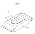
- a package body 100 of the wet wipes has: a package main body 20 having an opening portion 21; a label member 22 attached to the exterior face of the package main body 20 to cover the opening portion 21; and a laminated body of the sheets 710, 720 contained inside the package main body 20.
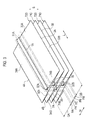
- Each of the sheets 710, 720 is contained inside the package main body 20 in a state where these sheets are folded back as shown in Figs. 2 and 3 .
- the sheet 720 has regions 31A, 32A, 33A, 34A, 35A, whereas the sheet 710 has regions 31B, 32B, 33B, 34B, 35B.
- the regions 31A, 32A are folded back along a folding line 1A; the regions 32A, 33A are folded back along a folding line 2A; the regions 33A, 34A are folded back along a folding line 3A; and the regions 34A, 35A are folded back along a folding line 4A.
- the regions 31B, 32B are folded back along a folding line 1B; the regions 32A, 33A are folded back along a folding line 2B; the regions 33A, 34A are folded back along a folding line 3B; and the regions 34A, 35A are folded back along a folding line 4B.
- the folding lines 1A, 2A are provided between the folding lines 3A, 4A in a widthwise direction W
- the folding lines 1B, 2B are provided between the folding lines 3B, 4B in the widthwise direction W.
- a region between the folding lines 1A, 2A in the widthwise direction W has a four-layered structure formed by folding back the regions 31A, 32A, 33A, 34A, whereas the other region has a two-layered structure formed by folding back the regions 33A, 34A.
- the regions 31A, 32A rise in a lamination direction S of the laminated body while extending in one direction L of the laminated body.
- the regions 31A, 32A are folded back along the folding lines 1A, 2A to thereby configure a rising region PA which is formed in the laminated body so as to rise in the lamination direction S while extending in the one direction L.
- a region between the folding lines 1B, B in the widthwise direction W has a four-layered structure formed by folding back the regions 31B, 32B, 33B, 34B, whereas the other region has a two-layered structure formed by folding back the regions 33B, 34B.
- the regions 31B, 32B rise in a lamination direction S of the laminated body while extending in the one direction L of the laminated body.
- the regions 31B, 32B are folded back along the folding lines 1B, 2B to thereby configure a rising region PB which is formed in the laminated body so as to rise in the lamination direction S while extending in the longitudinal direction L.
- one region (that is, the rising region PA) between the folding lines 1B, B in the widthwise direction W is arranged so as not to be overlapped with the other region (that is, the rising region PB) between the folding lines 1B, B in the direction W.
- the sheets 710, 720 adjacent to each other in the lamination direction S are laminated in close contact with each other with a predetermined chemical intervened therebetween.
- wet wipes manufactured with the manufacturing apparatus 10 according to the first embodiment of the present invention are not configured as the aforementioned pop-up type. Therefore, even in a case where the sheet 720 is taken out through the opening portion 21 of the package main body 20, the sheet 710 is not pulled up together to be protruded from the opening portion 21.
- step S101 the folding unit 5 folds respective sheets 71, 72 having been sent out from a wound state in a roller shape, into a predetermined shape (specifically, a shape shown in Figs. 2 and 3 ) on a side not in contact with a conveyance device.
- a predetermined shape specifically, a shape shown in Figs. 2 and 3
- the sheets 71, 72 have a basis weight of 25 g/m 2 to 100 g/m 2 , and are made of: fibers made of a hydrophilic fiber such as rayon, cotton, or pulp, and a simple substance such as PET, PP, PE, or acrylic; or hydrophobic composite fibers having a sheath-core structure or a side-by-side structure.
- a hydrophilic fiber such as rayon, cotton, or pulp
- a simple substance such as PET, PP, PE, or acrylic
- hydrophobic composite fibers having a sheath-core structure or a side-by-side structure.
- the sheets 71, 72 are a nonwoven fabric shaped in a sheet-like form by a spun lace method, an air-laid method, a direct spinning method, or the like, and these sheets are required to include a hydrophilic fiber in terms of permeability of the predetermined chemical at the time of impregnation of the predetermined chemical.
- step S102 an impregnating unit 1 impregnates each of the folded sheets 71, 72 with a predetermined amount of predetermined chemical from a side in contact with the conveyance device (a side of a conveyance roller 2).
- step S103 each of the sheets 71, 72 impregnated with the predetermined chemical is conveyed in contact with the surface of the conveyance roller 2.
- step S104 a conveyer 3 laminates each of the sheets 71, 72 impregnated with the predetermined chemical.
- the sheet 72 with its surface impregnated with the predetermined chemical being faced to the side in contact with the conveyance device is laminated from the side not in contact with the conveyance device, on the sheet 71 with its surface impregnated with the predetermined chemical being faced to the side in contact with the conveyance device.
- a cutting unit 4 cuts the sheets 71, 72 conveyed by the conveyer 3, into the sheets 710, 720 with a predetermined size.
- the laminated body 800 is conveyed in pressing step S107 while both outer end portions in the widthwise direction of the laminated body 800 formed of the cut-out sheets 710, 720 are pressed from a side not in contact with the conveyer 14.
- packaging step S108 the laminated body 800 is packaged in the package main body 20.
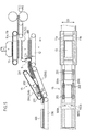
- the manufacturing apparatus 10 has: the folding unit 5; the impregnating unit 1; the conveyance roller 2; conveyors 3, 9, 11, 12; the cutting unit 4; the pusher 13; and a pressing device 15.
- the conveyance roller 2 and the conveyors 3, 9 make up a conveyance device configured to continuously convey the plurality of sheets 71, 72.
- the conveyers 11, 12, 14 make up a conveyance device configured to continuously convey the laminated body 800.
- the folding unit 5 is configured to fold back each of the sheets 71, 72 on a side not in contact with the conveyance device. Specifically, the folding unit 5 is configured to fold back each of the sheets 71, 72 so that the sheets 71, 72 are formed in a shape shown in Figs. 2 and 3 .
- the folding unit 5 is configured so that: the regions 31A, 32A, 33A (or 31B, 32B, 33B) including one side edge of the sheet 72 (or 71) are folded back on a side not in contact with the conveyance device, along the folding line 3A (or 3B) in a conveyance direction MD; thereafter the regions 31A, 32A (or 31B, 32B) including one side edge of the sheet 72 (or 71) are folded back on the side not in contact with the conveyance device, along the folding line 2A (or 2B) in the conveyance direction MD; and thereafter, the region 31A (or 31B) including one side edge of the sheet 72 (or 71) is folded back on the side not in contact with the conveyance device, along the folding line 1A (or 1B) in the conveyance direction MD.
- the folding unit 5 is configured so that the region 35A (or 35B) including the other side edge of the sheet 72 (or 71) is folded back on a side in contact with the conveyance device, along the folding line 4A (or 4B) in the conveyance direction MD.
- the impregnating unit 1 is configured to impregnate each of the folded sheets 71, 72 with the predetermined chemical, from the side in contact with the conveyance device.
- the impregnating unit 1 may be configured to push out the predetermined chemical by a predetermined amount from a chemical tank by using a proportioning pump.
- the predetermined amount of predetermined chemical is discharged from a pore provided in the impregnating unit 1 and comes in contact with the sheets 71, 72, so that each of the sheets 71, 72 is impregnated with the predetermined amount of predetermined chemical.
- the impregnating unit 1 may be configured to impregnate the sheets 71, 72 with the predetermined chemical having weight of 3.5 (between 3 and 4) times heavier than the sheets 71, 72, for example.
- a weight rate (that is, an impregnation rate) of the predetermined chemical to be impregnated, with respect to the sheets 71, 72 is appropriately adjustable by the impregnating unit 1.
- an impregnation rate required for the sheets 71, 72 to adhere to the surface of the conveyance roller 2 and for the sheet 72 to adhere to the top of the sheet 71 is 1.5 times or more in a case of using as the sheets 71, 72, a spun lace nonwoven fabric of 38 g/m 2 having a rayon fiber as a main constituent, for example.
- the impregnating unit 1 may adopt a method for attaching a predetermined chemical in a droplet form or in a mist form to the sheets 71, 72.
- the above-described method is preferable in consideration of impregnation efficiency and process pollution of chemical at the time when surfaces of the sheets 71, 72, which are impregnated with the predetermined chemical, are brought in contact with the surface of the conveyance roller 2.
- the conveyance roller 2 is connected to a driving source and is a driving roller with a smooth surface, configured to rotate by itself.
- the conveyor 3 is configured to convey each of the sheets 71, 72 at an approximately equal conveyance speed to the conveyance roller 2.
- the cutting unit 4 is configured to cut the laminated body formed by laminating the plurality of sheets 71, 72 in a state where the sheets 71, 72 impregnated with the predetermined chemical are folded back.
- the cutting unit 4 is configured so that a cutter roller having a cutting blade on its surface and an anvil roller having a smooth surface cut the plurality of continuously-conveyed sheets at a predetermined interval in a direction perpendicular to the conveyance direction.
- the conveyor 9 may be provided at both the upside and downside.
- the laminated body of the sheets 710, 720 is conveyed while being sandwiched between an upper conveyer arranged at the upside and a lower conveyer arranged at the downside.
- This upper conveyor may be provided with a concave portion and a convex portion.
- the laminated body of the sheets 710, 720 after being cut by the cutting unit 4 is improved in its transfer ability and conveyance stability with respect to the conveyer 9.
- a conveyance speed of the conveyor 9 is 3% higher than the conveyor 3 and the cutting unit 4.
- the conveyer 11 has conveyers 11a, 11b arranged at a predetermined interval in a cross direction CD intersecting with the conveyance direction MD.
- the conveyers 11a, 11b are provided with a suction mechanism (not shown) to enable the cut-out sheets 710, 720 conveyed by the conveyer 9 to be conveyed with their outer ends in the widthwise direction being adsorbed to the conveyance surface.
- the pusher 13 is arranged between the conveyers 11a, 11b.
- the pusher 13 is arranged movably in a direction of pushing down the sheets 710, 720 conveyed by the conveyer 11, that is, in a direction of detaching the sheets 710, 720 from the conveyance surfaces of the conveyers 11a, 11b.
- the laminated body 800 is formed by laminating the predetermined number of sheets 710, 720 detached from the conveyers 11a, 11b, a stopper S is released and the laminated body 800 is conveyed by the conveyer 12 toward the pressing device 15.
- the pressing device 15 is configured so that the laminated body 800 formed by laminating the cut-out sheets 710, 720 is conveyed while both end portions in the conveyance direction of the laminated body 800 are pressed by a pressing portion from a side not in contact with the conveyer 14.
- the pressing device 15 has a plurality of rollers 201, 202, 203; press belts 204a, 204b wound around the plurality of rollers 201, 202, 203; and conveyance belts 205, 206 for conveying the laminated body 800.
- Any one of the plural rollers 201, 202, 203 is connected to a driving source and controlled so as to drive the press belts 204a, 204b at a predetermined speed in the conveyance direction.
- the conveyance belt 205 corresponds to the conveyance belt 14.
- the press belts 204a, 204b are wound around the rollers 201, 202, 203 and configured to be driven in association with the conveyance speed and the conveyance direction of the laminated body 800.
- the press belts 204a, 204b are arranged to be interspaced from each other at a predetermined interval in the cross direction CD intersecting with the conveyance direction MD.
- the predetermined interval is an interval that allows the press belts 204a, 204b to come in contact with both end portions 800A, 800B in the cross direction CD of the laminated body 800.
- the press belts 204a, 204b according to the present embodiment are formed in a round tubular shape. That is, the press belts 204, 204b have a cross section in a substantially circular shape.
- Interval D2 between the outermost periphery of the press belts 204a, 204b wound around the rollers 201, 202, 203, the outer most periphery which is most distant from the rotation axes of the rollers 201, 202, 203, and the conveyance surface of the conveyance belt 205 is made shorter than lamination height D1 of the laminated body 800.
- the interval D2 is adjusted to a height that the chemical is prevented from being squeezed out more than necessary.
- the press belts 204a, 204b are inclined so as to gradually decrease the interval from D1 to D2, between the outermost periphery of the press belts 204a, 204b and the conveyance belt 205. Accordingly, a force is gradually applied to the both outer end portions 800A, 800B in the widthwise direction of the laminated body 800 to be conveyed.
- the laminated body 800 can be conveyed while pressing the both end portions 800A, 800B, other than a central region 800C, of the laminated body 800.
- the sheets 71, 72 are conveyed in a stacked state, and after cutting, the predetermined number of sheets are laminated.
- the sheets 71, 72 which are stacked during conveyance are pressed against each other by means of the conveyer 3.
- a force of pressing in the laminating step S106 after cutting is smaller than a force of pressing by the conveyer 3 during conveyance.
- the plurality of sheets pressed strongly may possibly be taken out all stuck together.
- the laminated body 800 formed by laminating the predetermined number of sheets is pressed not by uniformly pressing the entire surface but pressing the both end portions 800A, 800B.
- adhesion between the sheets 710, 720 of the laminated body 800 after lamination of the plural sheets is not increased more than necessary, and adhesion to the sheet 710 subsequent to the sheet 720 can be maintained, thereby being able to avoid the situation that a plurality of sheets is undesirably taken out all stuck together.
- the surface of the laminated body 800 is not entirely pressed, it is possible to prevent variability in an impregnation amount which is caused by the fact that the chemical is shifted from sheets in the upper layer to sheets in the lower layer of the laminated body 800.
- the amount of predetermined chemical to be impregnated in the sheets can be uniformed between sheets in the upper layer side and sheets in the lower layer side. Furthermore, it is also possible to prevent reduction in the easiness of taking sheets out, which is caused by increase of the amount of predetermined chemical to be impregnated in the sheets.
- the press belts 204a, 204b are formed in a round tubular shape. This allows release between sheets in the upper surface side making up the laminated body 800 and the rollers 202, 203 making up the pressing device 15, thereby being able to prevent the sheets in the upper surface side from being wound around the rollers 202, 203.
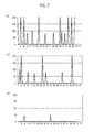
- a take-out test was performed by packaging the laminated body formed of seventy-two sheets in the package main body and taking sheets out one by one. The results are shown in Figs. 7(a) to 7(c) . Specifically, a manufacturing line that one set was formed by stacking four sheets was made. That is, the laminated body formed of eighteen sets was produced and sealed in the package body.
- Fig. 7(a) shows the results of a take-out test performed to the laminated body to which the pressing step was not performed.
- Fig. 7(b) shows the results of a take-out test performed to the laminated body in which the entire surface was pressed.
- Fig. 7(c) shows the results of a take-out performed to the laminated body to which the pressing step was performed by the pressing device according to the embodiment.
- the vertical axis shows the amount of a pulled-out portion of subsequent sheet in the event of pop-up (a phenomenon that a subsequent sheet is pulled out in association with a prior sheet).
- a portion is length (mm).
- the laminated body to which the pressing step was not performed has a strong tendency that four sheets are taken out at one time. That is, it turned out that one set of sheets stacked in the manufacturing line is prone to be taken out all stuck together. Furthermore, it turned out that even in a case of a laminated body with its entire surface being pressed, one set of sheets stacked in the manufacturing line is prone to be taken out all together.
- the present invention it is possible to provide a method and an apparatus for manufacturing wet wipes, by which such wet wipes can be manufactured, that are capable of preventing variability in an impregnation amount of a predetermined chemical and reduction in the easiness of taking sheets out, which is caused by increasing an impregnation rate of the predetermined chemical.
Landscapes
- Engineering & Computer Science (AREA)
- Mechanical Engineering (AREA)
- Sanitary Thin Papers (AREA)
- Laminated Bodies (AREA)
- Cleaning Implements For Floors, Carpets, Furniture, Walls, And The Like (AREA)
- Body Washing Hand Wipes And Brushes (AREA)
- Treatment Of Fiber Materials (AREA)
- Paper (AREA)
Abstract
Description
- The present invention relates to a method and an apparatus for manufacturing wet wipes.
- As a method for manufacturing wet wipes formed of a laminated body of sheets impregnated with a predetermined chemical, there are known methods disclosed in
Patent Literatures 1 and 2. - A method disclosed in
Patent Literature 1 has: a step of impregnating an original fabric with part of a predetermined chemical during conveyance of the original fabric before lamination; a step of squeezing out an excess of the predetermined chemical impregnated in the original fabric during conveyance of the original fabric; a step of laminating a plurality of original fabrics during conveyance of the original fabrics; and a step of impregnating the original fabrics with the rest of the predetermined chemical during conveyance of the original fabrics after lamination. - Further, a method disclosed in Patent Literature 2 has: a step of impregnating an original fabric with a predetermined chemical during conveyance of the original fabric before lamination; a step of laminating the original fabric while folding it back during conveyance of the original fabric; a step of conveying the original fabric after lamination while compressing it in a thickness direction and thereafter cutting the original fabric; and the like.
- The wet wipes manufactured by the methods disclosed in
Patent Literatures 1 and 2 have a configuration of a so-called pop-up type that when one sheet is taken out of a container, the next one is also pulled out together and protruded from an outlet of the container. -
- Patent Literature 1: Japanese Patent Publication No.
H7-204118 - Patent Literature 2: Japanese Patent Publication No.
2007-144053 - However, the pop-up type wet wipes described above have a problem that if an impregnation rate of a predetermined chemical to an original fabric is increased, the original fabrics are interconnected by means of a water screen of the predetermined chemical, which makes it difficult to take sheets out of the container one by one, so that the impregnation rate of the predetermined chemical to the original fabric has to be kept relatively low.
- Furthermore, the method disclosed in
Patent Literature 1 has a problem that the impregnation step of a predetermined chemical requires two stages to be taken before and after lamination of the original fabric, thereby increasing the size of apparatus, and since the original fabric after lamination is impregnated with the predetermined chemical, the impregnation amount of the predetermined chemical has variability between the surface part and the center part of the laminated body of sheets. - Furthermore, the method disclosed in Patent Literature 2 has a problem that the predetermined chemical is squeezed out of the original fabric because the original fabric is folded back and compressed after impregnation with the predetermined chemical, thereby leading to a possibility that a product containing a desired amount of the predetermined chemical cannot be manufactured.
- Thus, the present invention has been achieved in view of the aforementioned problem, and an object thereof is to provide a method and an apparatus for manufacturing wet wipes, by which such wet wipes can be manufactured, that are capable of preventing variability in an impregnation amount of a predetermined chemical and reduction in the easiness of taking sheets out, which is caused by increasing an impregnation rate of the predetermined chemical.
- A fist feature of the present invention is summarized as a method for manufacturing wet wipes formed of a laminated body of sheets impregnated with a predetermined chemical, the method comprising: a step of cutting an original fabric of a plurality of sheets at a predetermined interval in a cross direction perpendicular to a conveyance direction, the plurality of sheets being continuously conveyed by a conveyance device in a laminated state while being impregnated with the predetermined chemical and folded back; and a step of conveying the laminated body of the cut-out sheets while pressing both ends in the conveyance direction of the laminated body from a side not in contact with the conveyance device.
- Moreover, the feature of the present invention is summarized as a manufacturing device that manufactures wet wipes formed of a laminated body of sheets impregnated with a predetermined chemical, the manufacturing device comprising: a cutting unit that cuts a plurality of sheets at a predetermined interval in a cross direction perpendicular to a conveyance direction, the plurality of sheets being continuously conveyed by a conveyance device in a laminated state while being impregnated with the predetermined chemical and folded back; and the conveyance device that conveys the laminated body of the cut-out sheets while pressing both ends in the conveyance direction of the laminated body by means of a pressing portion, from a side not in contact with the conveyance device.
-
- [
Fig. 1] Fig. 1 is a perspective view of a package body of wet wipes manufactured by a manufacturing apparatus according to a first embodiment of the present invention. - [
Fig. 2] Fig. 2 is a view for showing a state in which the wet wipes manufactured by the manufacturing apparatus according to the first embodiment of the present invention are contained inside the package body. - [
Fig. 3] Fig. 3 is a view for showing a state in which the wet wipes manufactured by the manufacturing apparatus according to the first embodiment of the present invention are contained inside the package body. - [
Fig. 4] Fig. 4 is a schematic view of the manufacturing apparatus according to the first embodiment of the present invention. - [
Fig. 5] Fig. 5 is a view for illustrating devices used in a laminating step and a pressing step of the manufacturing apparatus according to the first embodiment of the present invention. - [
Fig. 6] Fig. 6 is a view for illustrating a configuration of a pressing device according to the first embodiment of the present invention. - [
Fig. 7] Fig. 7(a) shows results of a taking-out test for a package body to which a pressing step was not performed by the pressing device;Fig. 7(b) shows results of a taking-out test for a package body in which the entire surface of a laminated body was pressed; andFig. 7(c) shows results of a taking-out test for a package body to which the pressing step was performed by the pressing device according to the embodiment. - With reference to
Figs. 1 to 3 , wet wipes manufactured by amanufacturing apparatus 10 according to a first embodiment of the present invention are explained. Such wet wipes are formed of a laminated body ofsheets - As shown in
Fig. 1 , apackage body 100 of the wet wipes has: a packagemain body 20 having anopening portion 21; alabel member 22 attached to the exterior face of the packagemain body 20 to cover theopening portion 21; and a laminated body of thesheets main body 20. - Each of the
sheets main body 20 in a state where these sheets are folded back as shown inFigs. 2 and3 . - As shown in
Figs. 2 and3 , thesheet 720 hasregions sheet 710 hasregions - Herein, in the
sheet 720, theregions folding line 1A; theregions folding line 2A; theregions folding line 3A; and theregions folding line 4A. - Similarly, in the
sheet 710, theregions folding line 1B; theregions folding line 2B; theregions folding line 3B; and theregions folding line 4B. - Note that in the
sheet 720, thefolding lines folding lines sheet 710, thefolding lines folding lines - That is, in the
sheet 720, a region between thefolding lines regions regions - Therefore, the
regions - That is, the
regions folding lines - Similarly, in the
sheet 710, a region between thefolding lines 1B, B in the widthwise direction W has a four-layered structure formed by folding back theregions regions - Therefore, the
regions - That is, the
regions folding lines - Furthermore, one region (that is, the rising region PA) between the
folding lines 1B, B in the widthwise direction W is arranged so as not to be overlapped with the other region (that is, the rising region PB) between thefolding lines 1B, B in the direction W. - Furthermore, in the rising regions PA, PB, the
sheets - Herein, in regions RA, RB, RC adjacent to the rising regions PA, PB, since a gap is formed between the
sheets - Note that the wet wipes manufactured with the
manufacturing apparatus 10 according to the first embodiment of the present invention are not configured as the aforementioned pop-up type. Therefore, even in a case where thesheet 720 is taken out through theopening portion 21 of the packagemain body 20, thesheet 710 is not pulled up together to be protruded from theopening portion 21. - That is, after taking out the
sheet 720 through theopening portion 21 of the packagemain body 20 by grabbing and pulling up theregions sheet 710 by grabbing and pulling up theregions - Hereinafter, with reference to
Fig. 4 , a method for manufacturing wet wipes according to the present embodiment is briefly explained. - As shown in
Fig. 4 , in step S101, thefolding unit 5 foldsrespective sheets Figs. 2 and3 ) on a side not in contact with a conveyance device. - For example, the
sheets - Furthermore, the
sheets - In step S102, an impregnating
unit 1 impregnates each of the foldedsheets - In step S103, each of the
sheets - In step S104, a
conveyer 3 laminates each of thesheets - Specifically, with the
conveyer 3, thesheet 72 with its surface impregnated with the predetermined chemical being faced to the side in contact with the conveyance device is laminated from the side not in contact with the conveyance device, on thesheet 71 with its surface impregnated with the predetermined chemical being faced to the side in contact with the conveyance device. - In step S105, a
cutting unit 4 cuts thesheets conveyer 3, into thesheets - Thereafter, after a laminated
body 800 formed by laminating a predetermined number of the cut-outsheets body 800 is conveyed in pressing step S107 while both outer end portions in the widthwise direction of the laminatedbody 800 formed of the cut-outsheets conveyer 14. In packaging step S108, the laminatedbody 800 is packaged in the packagemain body 20. - Hereinafter, with reference to
Figs. 4 to 6 , each function of themanufacturing apparatus 10 according to the present embodiment is explained. - As shown in
Fig. 4 , themanufacturing apparatus 10 has: thefolding unit 5; the impregnatingunit 1; the conveyance roller 2;conveyors cutting unit 4; thepusher 13; and apressing device 15. Herein, in themanufacturing apparatus 10, the conveyance roller 2 and theconveyors sheets conveyers body 800. - The
folding unit 5 is configured to fold back each of thesheets folding unit 5 is configured to fold back each of thesheets sheets Figs. 2 and3 . - Specifically, the
folding unit 5 is configured so that: theregions folding line 3A (or 3B) in a conveyance direction MD; thereafter theregions folding line 2A (or 2B) in the conveyance direction MD; and thereafter, theregion 31A (or 31B) including one side edge of the sheet 72 (or 71) is folded back on the side not in contact with the conveyance device, along thefolding line 1A (or 1B) in the conveyance direction MD. - Furthermore, the
folding unit 5 is configured so that theregion 35A (or 35B) including the other side edge of the sheet 72 (or 71) is folded back on a side in contact with the conveyance device, along thefolding line 4A (or 4B) in the conveyance direction MD. - The impregnating
unit 1 is configured to impregnate each of the foldedsheets - For example, the impregnating
unit 1 may be configured to push out the predetermined chemical by a predetermined amount from a chemical tank by using a proportioning pump. As a result, the predetermined amount of predetermined chemical is discharged from a pore provided in theimpregnating unit 1 and comes in contact with thesheets sheets - Furthermore, the impregnating
unit 1 may be configured to impregnate thesheets sheets - Note that a weight rate (that is, an impregnation rate) of the predetermined chemical to be impregnated, with respect to the
sheets unit 1. - Herein, an impregnation rate required for the
sheets sheet 72 to adhere to the top of thesheet 71 is 1.5 times or more in a case of using as thesheets - Furthermore, as a method for applying a predetermined chemical, the impregnating
unit 1 may adopt a method for attaching a predetermined chemical in a droplet form or in a mist form to thesheets sheets - The conveyance roller 2 is connected to a driving source and is a driving roller with a smooth surface, configured to rotate by itself.
- The
conveyor 3 is configured to convey each of thesheets - The
cutting unit 4 is configured to cut the laminated body formed by laminating the plurality ofsheets sheets cutting unit 4 is configured so that a cutter roller having a cutting blade on its surface and an anvil roller having a smooth surface cut the plurality of continuously-conveyed sheets at a predetermined interval in a direction perpendicular to the conveyance direction. - Furthermore, like the
conveyor 3, theconveyor 9 may be provided at both the upside and downside. In such a case, the laminated body of thesheets - As a result, the laminated body of the
sheets cutting unit 4 is improved in its transfer ability and conveyance stability with respect to theconveyer 9. - Herein, a conveyance speed of the
conveyor 9 is 3% higher than theconveyor 3 and thecutting unit 4. - The
conveyer 11 hasconveyers conveyers sheets conveyer 9 to be conveyed with their outer ends in the widthwise direction being adsorbed to the conveyance surface. Thepusher 13 is arranged between theconveyers - The
pusher 13 is arranged movably in a direction of pushing down thesheets conveyer 11, that is, in a direction of detaching thesheets conveyers - After the
laminated body 800 is formed by laminating the predetermined number ofsheets conveyers laminated body 800 is conveyed by theconveyer 12 toward thepressing device 15. - The
pressing device 15 is configured so that thelaminated body 800 formed by laminating the cut-outsheets laminated body 800 are pressed by a pressing portion from a side not in contact with theconveyer 14. - The
pressing device 15 has a plurality ofrollers press belts rollers conveyance belts laminated body 800. - Any one of the
plural rollers press belts conveyance belt 205 corresponds to theconveyance belt 14. - The
press belts rollers laminated body 800. Thepress belts press belts end portions laminated body 800. - The
press belts press belts 204, 204b have a cross section in a substantially circular shape. - Interval D2 between the outermost periphery of the
press belts rollers rollers conveyance belt 205 is made shorter than lamination height D1 of thelaminated body 800. The interval D2 is adjusted to a height that the chemical is prevented from being squeezed out more than necessary. - The
press belts press belts conveyance belt 205. Accordingly, a force is gradually applied to the bothouter end portions laminated body 800 to be conveyed. - With the manufacturing method and the
manufacturing apparatus 10 according to the present embodiment, by means of thepressing device 15 configured as described above, thelaminated body 800 can be conveyed while pressing the bothend portions central region 800C, of thelaminated body 800. - In the manufacturing method according to the present embodiment, the
sheets sheets conveyer 3. However, a force of pressing in the laminating step S106 after cutting is smaller than a force of pressing by theconveyer 3 during conveyance. - This is partially because the pressing force cannot be increased for the reason that the entire surface of the
laminated body 800 could be pressed after the laminating step S106 but in such a case, the chemical would be undesirably shifted to the lower layer side of thelaminated body 800 to cause the shortage of the chemical amount in sheets at the upper layer side. - As described above, if there is a difference between an adhesion force between the sheets which are stacked during conveyance and an adhesion force between the sheets which are stacked in the laminating step S106, the plurality of sheets pressed strongly may possibly be taken out all stuck together.
- On the other hand, in the manufacturing method according to the present embodiment, after the laminating step S107, the
laminated body 800 formed by laminating the predetermined number of sheets is pressed not by uniformly pressing the entire surface but pressing the bothend portions - Therefore, adhesion between the
sheets laminated body 800 after lamination of the plural sheets is not increased more than necessary, and adhesion to thesheet 710 subsequent to thesheet 720 can be maintained, thereby being able to avoid the situation that a plurality of sheets is undesirably taken out all stuck together. - Furthermore, since the surface of the
laminated body 800 is not entirely pressed, it is possible to prevent variability in an impregnation amount which is caused by the fact that the chemical is shifted from sheets in the upper layer to sheets in the lower layer of thelaminated body 800. - With the manufacturing method and the
manufacturing apparatus 10 according to the present embodiment, the amount of predetermined chemical to be impregnated in the sheets can be uniformed between sheets in the upper layer side and sheets in the lower layer side. Furthermore, it is also possible to prevent reduction in the easiness of taking sheets out, which is caused by increase of the amount of predetermined chemical to be impregnated in the sheets. - In the
manufacturing apparatus 10 according to the present embodiment, thepress belts laminated body 800 and therollers pressing device 15, thereby being able to prevent the sheets in the upper surface side from being wound around therollers - Thus, the present invention has been explained in detail by using the above-described embodiments; however, it is obvious that for persons skilled in the art, the present invention is not limited to the embodiments explained herein. The present invention can be implemented as corrected and modified modes without departing from the gist and the scope of the present invention defined by the claims. Therefore, the description of the specification is intended for explaining the example only and does not impose any limited meaning to the present invention.
- A take-out test was performed by packaging the laminated body formed of seventy-two sheets in the package main body and taking sheets out one by one. The results are shown in
Figs. 7(a) to 7(c) . Specifically, a manufacturing line that one set was formed by stacking four sheets was made. That is, the laminated body formed of eighteen sets was produced and sealed in the package body. -
Fig. 7(a) shows the results of a take-out test performed to the laminated body to which the pressing step was not performed.Fig. 7(b) shows the results of a take-out test performed to the laminated body in which the entire surface was pressed.Fig. 7(c) shows the results of a take-out performed to the laminated body to which the pressing step was performed by the pressing device according to the embodiment. InFigs. 7(a) to 7(c) , the vertical axis shows the amount of a pulled-out portion of subsequent sheet in the event of pop-up (a phenomenon that a subsequent sheet is pulled out in association with a prior sheet). A portion is length (mm). - According to the results, it turned out that the laminated body to which the pressing step was not performed has a strong tendency that four sheets are taken out at one time. That is, it turned out that one set of sheets stacked in the manufacturing line is prone to be taken out all stuck together. Furthermore, it turned out that even in a case of a laminated body with its entire surface being pressed, one set of sheets stacked in the manufacturing line is prone to be taken out all together.
- On the other hand, it turned out that a laminated body to which the pressing step is performed by the pressing device according to the embodiment hardly causes the pop-up and has a strong tendency that all of sheets can be taken out one by one.
- In addition, the entire content of
Japanese Patent Application No. 2010-222541 - According to the present invention, it is possible to provide a method and an apparatus for manufacturing wet wipes, by which such wet wipes can be manufactured, that are capable of preventing variability in an impregnation amount of a predetermined chemical and reduction in the easiness of taking sheets out, which is caused by increasing an impregnation rate of the predetermined chemical.
- 1...Impregnating unit, 2...Conveyance roller, 3...Conveyer, 4...Cutting unit, 5...Folding unit, 9...Conveyer, 10...Manufacturing apparatus, 11...Conveyer, 11a, 11b...Conveyer, 12...Conveyer, 13...Pusher, 14...Conveyance belt, 15...Pressing device, 20...Package main body, 21...Opening portion, 22...Label member, 70...Sheet, 71, 72...Sheet, 100...Package body, 201, 202, 203...Roller, 204a, 204b...Press belt, 205, 206...Conveyance belt, 710, 720...Sheet, 800...Laminated body, 800A, 800B...Both end portions, 800C ... Central region
Claims (3)
- A method for manufacturing wet wipes formed of a laminated body of sheets impregnated with a predetermined chemical, the method comprising:a step of cutting an original fabric of a plurality of sheets at a predetermined interval in a cross direction perpendicular to a conveyance direction, the plurality of sheets being continuously conveyed by a conveyance device in a laminated state while being impregnated with the predetermined chemical and folded back; anda step of conveying the laminated body of the cut-out sheets while pressing both ends in the conveyance direction of the laminated body from a side not in contact with the conveyance device.
- A manufacturing device that manufactures wet wipes formed of a laminated body of sheets impregnated with a predetermined chemical, the manufacturing device comprising:a cutting unit that cuts a plurality of sheets at a predetermined interval in a cross direction perpendicular to a conveyance direction, the plurality of sheets being continuously conveyed by a conveyance device in a laminated state while being impregnated with the predetermined chemical and folded back; andthe conveyance device that conveys the laminated body of the cut-out sheets while pressing both ends in the conveyance direction of the laminated body by means of a pressing portion, from a side not in contact with the conveyance device.
- The manufacturing device according to claim 2, wherein the pressing portion is formed in a round tubular shape and configured to be driven in association with a conveyance speed and a conveyance direction of the sheets.
Applications Claiming Priority (2)
| Application Number | Priority Date | Filing Date | Title |
|---|---|---|---|
| JP2010222541A JP5635353B2 (en) | 2010-09-30 | 2010-09-30 | Wet wipes manufacturing method and manufacturing apparatus |
| PCT/JP2011/071227 WO2012043279A1 (en) | 2010-09-30 | 2011-09-16 | Device for producing and method for producing wet wipes |
Publications (2)
| Publication Number | Publication Date |
|---|---|
| EP2623005A1 true EP2623005A1 (en) | 2013-08-07 |
| EP2623005A4 EP2623005A4 (en) | 2016-08-10 |
Family
ID=45892746
Family Applications (1)
| Application Number | Title | Priority Date | Filing Date |
|---|---|---|---|
| EP11828839.8A Withdrawn EP2623005A4 (en) | 2010-09-30 | 2011-09-16 | Device for producing and method for producing wet wipes |
Country Status (9)
| Country | Link |
|---|---|
| US (1) | US20130267401A1 (en) |
| EP (1) | EP2623005A4 (en) |
| JP (1) | JP5635353B2 (en) |
| CN (1) | CN102525319B (en) |
| AU (1) | AU2011309414A1 (en) |
| BR (1) | BR112013007193A2 (en) |
| MY (1) | MY164167A (en) |
| TW (1) | TWI531347B (en) |
| WO (1) | WO2012043279A1 (en) |
Cited By (2)
| Publication number | Priority date | Publication date | Assignee | Title |
|---|---|---|---|---|
| IT202100016211A1 (en) * | 2021-06-21 | 2022-12-21 | Tecnau Srl | SHEET STACKING EQUIPMENT |
| IT202100016238A1 (en) * | 2021-06-21 | 2022-12-21 | Tecnau Srl | EQUIPMENT FOR HIGH SPEED STACKING OF PAPER SHEETS |
Families Citing this family (5)
| Publication number | Priority date | Publication date | Assignee | Title |
|---|---|---|---|---|
| CN106006148B (en) * | 2016-05-19 | 2017-07-18 | 合肥博玛机械自动化有限公司 | A kind of shawl paper subpackage arranging machine |
| JP2018042957A (en) * | 2016-09-18 | 2018-03-22 | 勝 南野 | Wet cloth and cloth set |
| CN112960461B (en) * | 2021-02-04 | 2022-09-23 | 山东洁雅卫生用品有限公司 | Preparation and processing technology of infant wet tissue |
| CN113978860B (en) * | 2021-10-23 | 2023-05-02 | 郑州维普斯机械设备有限公司 | Wet piece of cloth automatic production lamination equipment |
| CN115285771B (en) * | 2022-08-04 | 2023-06-27 | 杭州国光旅游用品有限公司 | Circulating folding equipment for manufacturing makeup removing wet tissues and folding method thereof |
Family Cites Families (9)
| Publication number | Priority date | Publication date | Assignee | Title |
|---|---|---|---|---|
| JP2971315B2 (en) * | 1994-01-14 | 1999-11-02 | ユニ・チャーム株式会社 | Manufacturing method of wet tissue |
| JP2777871B2 (en) * | 1994-09-22 | 1998-07-23 | 大王製紙株式会社 | Manufacturing method of superimposed wet tissue |
| SE512760C2 (en) * | 1997-06-25 | 2000-05-08 | Sca Hygiene Prod Ab | Method and apparatus for moist compression of absorbent products |
| JP2001286410A (en) * | 2000-04-06 | 2001-10-16 | Fukuyoo Kosan Kk | Method for producing wet tissue package and variable folding plate apparatus used for the same |
| CN1130155C (en) * | 2001-03-22 | 2003-12-10 | 元山科技工业股份有限公司 | Manufacturing equipment for wet wipes |
| CN2488453Y (en) * | 2001-06-18 | 2002-05-01 | 元山科技工业股份有限公司 | Wet Wipe Manufacturing Device |
| JP4390212B2 (en) * | 2005-11-30 | 2009-12-24 | ピジョン株式会社 | Wet tissue and wet tissue manufacturing method |
| JP5130029B2 (en) * | 2007-11-20 | 2013-01-30 | ツインバード工業株式会社 | Rolling hand towel manufacturing equipment |
| JP2010222541A (en) | 2009-03-25 | 2010-10-07 | Asahi Kasei E-Materials Corp | Resin sealing sheet |
-
2010
- 2010-09-30 JP JP2010222541A patent/JP5635353B2/en not_active Expired - Fee Related
-
2011
- 2011-09-16 US US13/877,044 patent/US20130267401A1/en not_active Abandoned
- 2011-09-16 MY MYPI2013001121A patent/MY164167A/en unknown
- 2011-09-16 EP EP11828839.8A patent/EP2623005A4/en not_active Withdrawn
- 2011-09-16 WO PCT/JP2011/071227 patent/WO2012043279A1/en not_active Ceased
- 2011-09-16 BR BR112013007193A patent/BR112013007193A2/en not_active Application Discontinuation
- 2011-09-16 AU AU2011309414A patent/AU2011309414A1/en not_active Abandoned
- 2011-09-30 CN CN201110303829.5A patent/CN102525319B/en active Active
- 2011-09-30 TW TW100135593A patent/TWI531347B/en not_active IP Right Cessation
Cited By (4)
| Publication number | Priority date | Publication date | Assignee | Title |
|---|---|---|---|---|
| IT202100016211A1 (en) * | 2021-06-21 | 2022-12-21 | Tecnau Srl | SHEET STACKING EQUIPMENT |
| IT202100016238A1 (en) * | 2021-06-21 | 2022-12-21 | Tecnau Srl | EQUIPMENT FOR HIGH SPEED STACKING OF PAPER SHEETS |
| EP4108616A1 (en) * | 2021-06-21 | 2022-12-28 | Tecnau S.R.L. | Sheet stacking equipment |
| US12503330B2 (en) | 2021-06-21 | 2025-12-23 | Tecnau S.R.L. | Sheet stacking equipment |
Also Published As
| Publication number | Publication date |
|---|---|
| JP5635353B2 (en) | 2014-12-03 |
| AU2011309414A1 (en) | 2013-05-30 |
| US20130267401A1 (en) | 2013-10-10 |
| TWI531347B (en) | 2016-05-01 |
| TW201228626A (en) | 2012-07-16 |
| JP2012075591A (en) | 2012-04-19 |
| MY164167A (en) | 2017-11-30 |
| BR112013007193A2 (en) | 2016-06-14 |
| EP2623005A4 (en) | 2016-08-10 |
| CN102525319A (en) | 2012-07-04 |
| WO2012043279A1 (en) | 2012-04-05 |
| CN102525319B (en) | 2015-08-12 |
Similar Documents
| Publication | Publication Date | Title |
|---|---|---|
| EP2623004A1 (en) | Packaging structure | |
| EP2623448B1 (en) | Method and apparatus for producing wet wipes | |
| US20130267401A1 (en) | Method and apparatus for manufacturing wet wipes | |
| EP2554083B1 (en) | Method and apparatus for manufacturing wet wipes | |
| US9340002B2 (en) | Method of manufacturing wet wipes, manufacturing apparatus, and wet wipes | |
| KR20180016770A (en) | Mask pack manufacturing system |
Legal Events
| Date | Code | Title | Description |
|---|---|---|---|
| PUAI | Public reference made under article 153(3) epc to a published international application that has entered the european phase |
Free format text: ORIGINAL CODE: 0009012 |
|
| 17P | Request for examination filed |
Effective date: 20130422 |
|
| AK | Designated contracting states |
Kind code of ref document: A1 Designated state(s): AL AT BE BG CH CY CZ DE DK EE ES FI FR GB GR HR HU IE IS IT LI LT LU LV MC MK MT NL NO PL PT RO RS SE SI SK SM TR |
|
| DAX | Request for extension of the european patent (deleted) | ||
| RA4 | Supplementary search report drawn up and despatched (corrected) |
Effective date: 20160713 |
|
| RIC1 | Information provided on ipc code assigned before grant |
Ipc: B65H 31/10 20060101ALI20160707BHEP Ipc: A47L 13/17 20060101ALI20160707BHEP Ipc: B65H 29/24 20060101ALI20160707BHEP Ipc: B65H 29/32 20060101ALI20160707BHEP Ipc: B65H 39/10 20060101ALI20160707BHEP Ipc: A47K 10/16 20060101ALI20160707BHEP Ipc: A47K 7/00 20060101AFI20160707BHEP Ipc: B65H 45/08 20060101ALI20160707BHEP Ipc: B65H 35/08 20060101ALI20160707BHEP Ipc: B65H 31/30 20060101ALI20160707BHEP |
|
| GRAP | Despatch of communication of intention to grant a patent |
Free format text: ORIGINAL CODE: EPIDOSNIGR1 |
|
| INTG | Intention to grant announced |
Effective date: 20181002 |
|
| STAA | Information on the status of an ep patent application or granted ep patent |
Free format text: STATUS: THE APPLICATION IS DEEMED TO BE WITHDRAWN |
|
| 18D | Application deemed to be withdrawn |
Effective date: 20190213 |