EP2622957B1 - Binder for horticultural use - Google Patents
Binder for horticultural use Download PDFInfo
- Publication number
- EP2622957B1 EP2622957B1 EP11829474.3A EP11829474A EP2622957B1 EP 2622957 B1 EP2622957 B1 EP 2622957B1 EP 11829474 A EP11829474 A EP 11829474A EP 2622957 B1 EP2622957 B1 EP 2622957B1
- Authority
- EP
- European Patent Office
- Prior art keywords
- tape
- case
- heating cable
- guide
- binder
- Prior art date
- Legal status (The legal status is an assumption and is not a legal conclusion. Google has not performed a legal analysis and makes no representation as to the accuracy of the status listed.)
- Active
Links
Images










Classifications
-
- A—HUMAN NECESSITIES
- A01—AGRICULTURE; FORESTRY; ANIMAL HUSBANDRY; HUNTING; TRAPPING; FISHING
- A01G—HORTICULTURE; CULTIVATION OF VEGETABLES, FLOWERS, RICE, FRUIT, VINES, HOPS OR SEAWEED; FORESTRY; WATERING
- A01G17/00—Cultivation of hops, vines, fruit trees, or like trees
- A01G17/04—Supports for hops, vines, or trees
- A01G17/06—Trellis-work
- A01G17/08—Tools e.g. clips for attaching hops, vines, or boughs to trellis-work; Tying devices
-
- A—HUMAN NECESSITIES
- A01—AGRICULTURE; FORESTRY; ANIMAL HUSBANDRY; HUNTING; TRAPPING; FISHING
- A01G—HORTICULTURE; CULTIVATION OF VEGETABLES, FLOWERS, RICE, FRUIT, VINES, HOPS OR SEAWEED; FORESTRY; WATERING
- A01G17/00—Cultivation of hops, vines, fruit trees, or like trees
- A01G17/04—Supports for hops, vines, or trees
- A01G17/06—Trellis-work
- A01G17/08—Tools e.g. clips for attaching hops, vines, or boughs to trellis-work; Tying devices
- A01G17/085—Espalier machines; Tying machines
Definitions
- the present invention relates to a binder for horticultural use, which is to be used to tie stems and branches to a prop or a guiding string such that garden or agricultural products can be properly grown up, and more particularly, to a binder for horticultural use that, instead of a stapler for supplying staples, includes: a taper frame having a holder groove disposed at one side thereof; a binding heating cable unit having a binding heating cable for receiving electric current of a predetermined amount from a power supply unit; and a holder to which the binding heating cable unit is detachably attached, the holder being inserted into the holder groove, so that the binder for horticultural use can bind both ends of a tape together by partially melting the tape made of synthetic resin material by heat without using the staples.
- the present invention relates to a binder for horticultural use, in which a hook lever is smoothly operated in a head step by step to catch and draw out the tape and a push lever protrudes outwardly and presses the tape to a cutter blade so as to cut the tape, thereby reducing a damage of the tape and securely catching and drawing out the tape through the smooth operation of the hook lever, and providing a smooth cutting of the tape and enhancing durability by preventing a damage and transformation of the push lever while working because the push lever protrudes outwardly from the head and presses the tape to the cutter blade only when the tape is cut.
- stems or branches are broken or drop down onto the ground due to weight of the branches and fruits or due to a rainstorm while gradually growing up from young seedlings, and hence, in order to prevent the above problems, props are set up at predetermined intervals, guiding strings are mounted thereto, and then, the stems or branches are tied and fixed to the props and guiding strings.
- stems and branches are tied to props and guiding strings to fix them to grow straight.
- the conventional horticultural binder which is one of the prior arts includes: a handle frame 10' having pins 11' protrudingly formed at both sides of the middle part and a stopper 12' disposed at a front end portion; a tape guide 20' attached to a lower face of the handle frame 10' and having a tape case 21'; a stapler 30 rotatably mounted inside the handle frame 10' and having staples therein; an arm 40' rotatably mounted to the handle frame 10' and having a clincher 41' opposed to the stapler 30; a head 50' mounted inside the arm 40' to catch and draw out a tape; and a link 60' rotatably mounted to the arm 40' and having a handle 61' mounted at one side thereof and a hook 62' mounted at the other side.
- both ends of the tape wound on the branches of the crops and the props or the guiding strings are bound by staples of the stapler 30, and at the same time, cut by a cutter blade mounted on the handle frame 10'.
- the conventional horticultural binder has various problems due to the staples used in the stapler method because the stapler 30 is used to bind both ends of the tape, and hence, there is a demand to continuously study and develop the horticultural binder.
- Chinese utility model CN201341351Y discloses a bundling machine structure comprising a handle frame having pins protrudingly formed on both sides in the middle of the handle frame and a stopper outwardly protruding from a front end portion thereof; a tape guide attached to a lower face of the handle frame and having a tape case; a taper rotatably mounted inside the handle frame; an arm rotatably mounted on the handle frame and having a clincher at an end portion opposed to the taper; a head mounted inside the arm for catching and drawing out a tape; and a link rotatably mounted on the arm and having a handle disposed at one side thereof and a hook disposed at the other side thereof, wherein the taper comprises a binding heating cable which is disposed so as to receive an electric current from a power supply unit; wherein the binding heating cable is opposed to the clincher for binding both ends of a tape, which is interposed between the binding heating cable and the clincher, by heat.
- the present invention has been made in an effort to solve the above-mentioned problems occurring in the conventional binder for horticultural use which binds stems and branches to props and guiding strings in order to let garden products or crops grow properly.
- the conventional binder for horticultural use according to the prior art having the stapler using staples has several problems in that the staples must be continuously supplied for a continuous use of the binder, in that the staples supplied from the stapler are exactly coincided with the staple grooves of the clincher of the arm to properly bind both ends of the tape by the staples, in that the user has to stop work in the case that the staples are fit into the stapler in a bent state or are exhausted, in that the binder cannot catch and cut the tape smoothly, and in that the tape is not securely caught because the front end of the tape is damaged or torn.
- the present invention provides a binder for horticultural use comprising: a handle frame having pins protrudingly formed on both sides in the middle of the handle frame and a stopper outwardly protruding from a front end portion thereof; a tape guide attached to a lower face of the handle frame and having a tape case; a taper rotatably mounted inside the handle frame; an arm rotatably mounted on the handle frame and having a clincher at an end portion opposed to the taper; a head mounted inside the arm for catching and drawing out a tape; and a link rotatably mounted on the arm and having a handle disposed at one side thereof and a hook disposed at the other side thereof, wherein the taper comprises: a taper frame; and a binding heating cable unit having a binding heating cable which is disposed so as to receive an electric current from a power supply unit; wherein the binding heating cable is opposed to the clincher for binding both ends of a tape, which is interposed
- the head of the binder can include: a case having an upper case and a lower case; a hook lever mounted inside the case and fit to a tension spring in such a way as to be operated rotatably; a cam plate mounted inside the case and having a cam hole; a first guide mounted inside the case and having a retainer to which a cam hole and a spring are fit; a second guide mounted inside the case and having a retainer to which a cam hole and a spring are fit; a support mounted inside the case; a rotational lever mounted inside the case and rotated by operation of the first guide and the second guide; and a push lever mounted inside the case and going into and out of the case by operation of the rotational lever.
- the binder for horticultural use according to the present invention can bind both ends of the tape together by heat by partially melting the tape made of synthetic resin material without using staples because using the taper instead of the stapler. Therefore, the binder for horticultural use according to the present invention can prevent the problems of the conventional binder that the staples must be continuously supplied for a continuous use of the binder, that the staples supplied from the stapler are exactly coincided with the staple grooves of the clincher of the arm to properly bind both ends of the tape by the staples, that the user has to stop work in the case that the staples are fit into the stapler in a bent state or are exhausted.
- the binder for horticultural use according to the present invention can firmly bind both ends of the tape together by heat.
- the hook lever is smoothly operated step by step to catch and draw out the tape, and the push lever protrudes outwardly and presses the tape to the cutter blade so as to cut the tape, so that the binder for horticultural use can reduce a damage of the tape and securely catch and draw out the tape through the smooth operation of the hook lever, and can provide a smooth cutting of the tape and enhance durability by preventing a damage and transformation of the push lever while working because the push lever protrudes outwardly from the head and presses the tape to the cutter blade only when the tape is cut.
- the present invention relates to a binder for horticultural use, which is to be used to bind stems and branches to props or guiding strings such that a garden or agricultural product can be properly grown.
- the binder for horticultural use which is to be used to bind stems and branches to props or guiding strings such that a garden or agricultural product can be properly grown, includes a handle frame 10, a tape guide 20, a taper 31, an arm 40, a head 50, and a link 60.
- the taper 31 includes: a taper frame 32 to which a cover is attached and which has a holder groove 33 disposed at one side thereof; a binding heating cable unit 35 having a binding heating cable 34 which is disposed so as to receive an electric current from a power supply unit 70; and a holder 36 to which the binding heating cable unit 35 is detachably attached, the holder 36 being inserted into the holder groove 33.
- the binding heating cable 34 is opposed to a clincher 41 for binding both ends of a tape T, which is interposed between the binding heating cable 34 and the clincher 41, by heat.
- FIGS. 1 to 31 the preferred embodiment of the present invention will be described in detail as follows.
- the handle frame 10 of the binder for horticultural use includes pins 11 protrudingly formed on both sides in the middle of the handle frame 10 and a stopper 12 outwardly protruding from a front end portion thereof.
- the tape guide 20 has a tape case 21 disposed at one side thereof, is attached to a lower face of the handle frame 10, and is disposed in such a fashion that the tape T is released from a tape reel accommodated in the tape case 21 and drawn out through the inside of the tape guide 20.
- the arm 40 has the clincher 41 mounted at an upper end portion opposed to the taper 31 and a lower end portion of the arm 40 is rotatably mounted on a lower portion of the handle frame 10.
- the head 50 is mounted inside an upper part of the arm 40, and a front end portion of the head 50 is caught and drawn out by a hook lever which is rotatably operated.
- the link 60 is rotatably mounted on the arm 40, and includes: a handle 61 disposed at one side so that a user can grasp it with the hand; and a hook 62 disposed at the other side joined to the pin 11 of the handle frame 10.
- both ends of the tape T wound on the branches of the crops and the props or the guiding strings are bound together by heat generated from the taper 31 while the clincher 41 is pressurized to the taper 31, and at the same time, a cutter blade C mounted on the handle frame 10 cuts the tape T.
- the binder for horticultural use according to the present invention binds the branches of the crops to the props or the guiding strings with the tape T so that the crops grow properly, because the tape T is wound onto the branches of the crops and the props or the guiding strings, both ends of the tape T are bound together by heat generated from the taper 31 and the tape T is cut by the cutter blade C.
- the taper 31 which is one of essential parts of the present invention includes: a taper frame 32 rotatably mounted inside the handle frame 10 and having a holder groove 33 disposed at one side; a binding heating cable unit 35 having a binding heating cable 34 which is disposed so as to receive an electric current from a power supply unit 70; and a holder 36 to which the binding heating cable unit 35 is detachably attached, the holder 36 being inserted into the holder groove 33.
- the binding heating cable 34 is opposed to the clincher 41 for binding both ends of a tape T, which is interposed between the binding heating cable 34 and the clincher 41, by heat.
- the binder for horticultural use according to the prior art binds both ends of the tape T winding the branches of the crops and the props or the guiding strings by bending the staples of the stapler 30 with the clincher 41
- the binder for horticultural use according to the present invention has the taper 31 instead of the stapler 30 providing the staples so as to partially melt the tape T made of synthetic resin material by heat to thereby bind both ends of the tape T together without using the staples.
- the holder groove 33 formed in one side (in direction that the head 50 is disposed) of the taper frame 32 is formed at the position, to which the staples of the stapler 30 of the conventional binder for horticultural use are provided, so as to supply an electric current to the heating unit which supplies not the staples but heat, and the holder 36 is inserted into the holder groove 33 in such a way as to detachably mount the heating unit.
- a head corresponding unit 63 which has an auxiliary blade 13 and a tape leading portion 64 is joined to an outer face of the holder groove 33 of the taper frame 32 so that a hook 53-2 of the hook lever of the head 50 surely catches the tape T supplied from the tape leading portion 64 and the cutter blade T which is the auxiliary blade 13 easily cuts the tape T.
- the binding heating cable unit 35 having the binding heating cable 34 which receives the electric current of a predetermined amount from the power supply unit 70 has a predetermined resistance
- the binding heating cable unit 35 partially melts the tape T made of synthetic resin material using the heating cable which generates heat, and hence, both ends of the tape T are bound together by a binding force of the synthetic resin material generated from the melted portion.
- the binding heating cable unit 35 having the binding heating cable 34 is detachably attached to the holder 36.
- the binder can simply receive electric power from the holder 36, and shows an effect that the binding heating cable 34 is replaced with a new one by separating the binding heating cable unit 35 from the holder 36 like a fuse in the case that the binding heating cable 35 is broken during use (In this instance, it is obvious that those skilled in the art can unite the binding heating cable unit 35 and the holder 36 on their judgment.).
- the binder having the binding heating cable 34 can solve the problems of the conventional binder using the stapler 30 having the staples, that continuously supplies the staples for a continuous use and that the user must stop work when the staples are fit into the stapler 30 in a bent state or are exhausted.
- the bind for horticultural use according to the present invention binds both ends of the tape T together by partially melting the tape T made of synthetic resin material not by the staples but by heat, it can use the tape T which is thinner than that of the conventional binder using the staples.
- both ends of the tape T can be bound together smoothly without regard to volume of the electric current applied to the binding heating cable 34 or temperature of heat generated from the binding heating cable 34 due to resistance of the binding heating cable 34.
- the clincher 41 can apply a pressurizing force of a predetermined amount to both ends of the tape T when the binding heating cable 34 is located just on the corresponding face of the binding heating cable 34, it can solve the problem of the conventional binder that the staples can bind both ends of the tape T properly only when the staples supplied from the stapler 30 and the staple grooves of the clincher 41 of the arm are exactly coincided with each other.
- the clincher 41 partially accommodates the both ends of the tape T and the binding heating cable 34 corresponding in a direction of the clincher 41 and being pressurized by the clincher 41 when pressurizing the handle 61 to tighten the arm 40 because the clincher 41 has an elastic force of a predetermined amount at the face opposed to the binding heating cable 34 of the taper 31, and may further include a nonflammable elastic body 42 with minor transformation and damage even by heat generated from the binding heating cable 34.
- the binder further includes a cutting heating cable unit 35' having a cutting heating cable 34' which receives an electric current of a predetermined amount from the power supply unit 70.
- the holder 36 can detachably hold the cutting heating cable unit 35' as well as the binding heating cable unit 35, and the clincher 41 is also opposed to the cutting heating cable 34' so as to cut both ends of the tape T introduced between the cutting heating cable 34' and the clincher 41.
- electrodes of the cutting heating cable unit 35' are respectively put into the anode and cathode of the power socket of the holder 36 for connecting the electrodes of the binding heating cable unit 35 and the electrodes of the cutting heating cable unit 35', so that the binder can easily receive electric power from the holder 36, and the cutting heating cable 34' is replaced with a new one by separating the cutting heating cable unit 35' from the holder 36 in the case that the cutting heating cable 35' is broken during use.
- the binder according to the present invention needs a smaller power than the conventional binder when the user grasps and pressurizes the handle 61.
- the power supply unit 70 supplies the electric current of a predetermined amount to the holder 36 to which the electrodes of the binding heating cable unit 35 having the binding heating cable 34 or the cutting heating cable unit 35' having the cutting heating cable 34' in order to supply electric power of the predetermined amount to the binding heating cable 34 or the cutting heating cable 34' .
- the supplied electric current may be supplied through any part of the binder for horticultural use according to the present invention, but it is preferable that an electric wire is disposed inside the taper frame 32 so that electric current is safely supplied to the holder from the power supply unit 70 which is disposed outside the binder for horticultural use according to the present invention.
- the power supply unit 70 disposed outside the binder uses a primary cell or a secondary cell so that the user can work smoothly and the electric wire 71 is elongated as long as the user can hold it.
- the power supply unit 70 may be disposed at one side of the tape case 21 in such a way as to be formed integrally with the binder for horticultural use, and hence, it can enhance workability through the simplified power supply unit 70.
- a control module (not shown in the drawings) is mounted at a position of the power supply unit 70 or the binder for horticultural use, and then, the binder for horticultural use according to the present invention can supply a proper amount of electric current to the binding heating cable 34 for a proper period of time so as to firmly bind the tape T and can supply a proper amount of electric current to the cutting heating cable 34' for a proper period of time so as to cut a predetermined position of the tape T bound by the binding heating cable 34.
- the control module can control the electric voltage.
- the binder for horticultural use according to the present invention may further include an operation sensor 37 which is mounted between the taper frame 32 and the handle frame 10 to control supply of the electric current to the binding heating cable 34 or the cutting heating cable 34'.
- an operation sensor 37 which is mounted between the taper frame 32 and the handle frame 10 to control supply of the electric current to the binding heating cable 34 or the cutting heating cable 34'.
- electric current is excessively consumed and the lifespan of the binding heating cable 34 or the cutting heating cable 34' may be reduced if the electric current supplied from the power supply unit 70 is always supplied to the binding heating cable 34 or the cutting heating cable 34' during work. Therefore, it is preferable that the operation sensor 37 for controlling the supply of the electric current from the power supply unit 70 is disposed in link with any part of the binder.
- the operation sensor 37 is interposed between the taper frame 32 and the handle frame 10 so as to be operated by the user's pressing force applied to the handle 61 to bind both ends of the tape T together.
- the binder may further include an elastic member 38 disposed between the taper frame 32 and the handle frame 10.
- the elastic member 38 buffs some of the user's pressing force applied to the handle 61 to bind both ends of the tape T together, such that it can prevent the clincher 41 and the binding heating cable unit 35 or the clincher 41 and the cutting heating cable unit 35' from being damaged due to an excessive pressing force and that it makes the operation sensor 37 be operated by not only a sensor-operation method but also a switching method in the case that the operation sensor 37 is disposed between the taper frame 32 and the handle frame 10.
- the head 50 is embedded in an upper portion of the arm 40, and the hook lever 53 is rotatably operated to catch and draw out the front end portion of the tape T.
- the link 60 is rotatably mounted on the arm 40, has the handle 61 disposed at one side thereof for allowing the user to grasp it with then hand and the hook 62 disposed at the other side so as to be joined to the pin 11 of the handle frame 10.
- the tape T is wound on the branches of the crops and the props or the guiding strings, the tape T is bound by the binding heating cable 34 and the clincher 41 and is cut by the cutter blade C, and hence, the branches of the crops are bound to the props or the guiding strings by the tape T so that the crops can grow properly.
- the head 50 of the binder includes: a case having an upper case 51 and a lower case 52; a hook lever 53 mounted inside the case and fit to a tension spring 53-5 in such a way as to be operated rotatably; a cam plate 54 mounted inside the case and having a cam hole 54-1; a first guide 55 mounted inside the case and having a retainer 55-3 to which a cam hole 55-1 and a spring 55-5 are fit; a second guide 56 mounted inside the case and having a retainer 56-3 to which a cam hole 56-1 and a spring 56-5 are fit; a support 57 mounted inside the case; a rotational lever 58 mounted inside the case and rotated by operation of the first guide 55 and the second guide 56; and a push lever 59 mounted inside the case and going into and out of the case by operation of the rotational lever 58.
- the case of the head 50 has the upper case 51 and the lower case 52, a pin 51-1 is fit to the upper case 51 and the lower case 52, and the hook lever 53, the cam plate 54, the first guide 55, the second guide 56, the support 57, the rotational lever 58 and the push lever 59 are mounted inside the upper case 51 and the lower case 52.
- the hook lever 53 includes: an elongated hole 53-1, which is formed at one side thereof, and, to which the pin 51-1 is fit; a hook 53-2 formed at a front end of the opposite side; an operation pin 53-3 and a fixing shaft 53-4 formed symmetrically to each other at the central portion; and the tension spring 53-5 fit onto the fixing shaft 53-4.
- the cam plate 54 is arranged below the hook lever 53, and includes: the cam hole 54-1 formed at one side in a shape of " ", to which the operation pin 53-3 is fit; and a joining hole 54-2 formed at the other side, to which the pin 51-1 is fit.
- the first guide 55 is arranged below the cam plate 54, and includes: the cam hole 55-1 formed at the central portion thereof in a shape of " ", to which the operation pin 53-3 of the hook lever 53 is fit; an elongated hole 55-2 formed in one side thereof, to which the pin 51-1 is fit; the retainer 55-3 formed below the cam hole 55-1 and supported by the spring 55-5 fit thereto; and a recess 55-4 formed in the opposite side of the elongated hole 55-2.
- the second guide 56 is arranged below the first guide 55, and includes: the cam hole 56-1 formed at the central portion thereof in a shape of " ", to which the operation pin 53-3 of the hook lever 53 is fit; an elongated hole 56-2 formed in one side thereof, to which the pin 51-1 is fit; the retainer 56-3 formed above the cam hole 56-1 and supported by the spring 56-5 fit thereto; and a recess 56-4 formed in the opposite side of the elongated hole 56-2.
- the support 57 serves to catch the tape T by engaging with the hook lever 53, and is mounted and fixed inside the front end portion of the case in such a way as to be opposed to the stopper 12 of the handle frame 10 and the binding heating cable 34.
- the rotational lever 58 is rotated according to the operations of the first guide 55 and the second guide 56, and includes: a first rotational pin 58-1 formed at the bottom face of the central portion thereof and rotatably assembled to the case; and a second rotational pin 58-2 formed at the bottom face of one side in such a way as to be inserted into the recesses 55-4 and 56-4 of the first guide 55 and the second guide 56.
- the push lever 59 serves to go into and out of the case according to the operation of the rotational lever 58, and includes the retainer 59-1 movably fit between the front end portion of the case and the upper portion of the support 57 and supported by the spring 59-2 fit at the rear end portion thereof.
- the pin 51-1 is fit into the elongated hole 56-2 in such a fashion that the second guide 56 is mounted inside the lower case 52, and the first guide 55 is put on the second guide 56 and the pin 51-1 is fit into the elongated hole 55-2.
- the springs 55-5 and 56-5 are respectively fit to the retainers 55-3 and 56-3 of the first guide 55 and the second guide 56 so as to elastically support the retainers 55-3 and 56-3, and then, the rotational lever 58 is fit to the lower case 52 in such a fashion that the rotational pin 58-2 is inserted into the recesses 55-4 and 56-4 of the first guide 55 and the second guide 56.
- the cam plate 54 is put on the first guide 55 and the pin 51-1 is inserted into the joining hole 54-2, and the hook lever 53 is elastically mounted on the cam plate 54 in such a fashion that the pin 51-1 is fit into the elongated hole 53-1, the operation pin 53-3 is fit into the cam holes 54-1, 55-1 and 56-1 formed in the cam plate 54, the first guide 55 and the second guide 56, and the tension spring 53-5 is fit to the fixing shaft 53-4.
- the support 57 is mounted below the front end portions of the upper case 51 and the lower case 52, and then, the push lever 59 is movably fit on the support 57 in such a way as to receive the elastic force of the spring 59-2.
- the arm 40 is in an opened state, and as shown in FIGS. 18 and 19 , the operation pin 53-3 of the hook lever 53 is caught to an upper stepped jaw of the cam hole 55-1 of the first guide 55, so that the hook lever 53 is in a upwardly rotated state.
- first guide 55 and the second guide 56 are pressurized to the stopper 12 of the handle frame 10 and pushed backward, and hence, the operation pin 53-3 of the hook lever 53 is ascended from the cam hole 54-1 of the cam plate 54 to the upper stepped jaw. Then, the hook lever 53 is separated from the tape T while rotating upward, and at the same time, the rotational lever 58 is rotated by the operation of the first guide 55 and the second guide 56 to thereby push out the push lever 59, and then, the front end portion of the push lever 59 presses the tape T to the cutter blade C to thereby cut the tape T.
- the rotational lever 58 pulls the push lever 59 to the inside of the case so that the push lever 59 is located in the initial state while being rotated by the operation of the first guide 55 and the second guide 56 so as to be located in the initial state.
- the binder for horticultural use according to the present invention can reduce a damage of the tape and securely catch and draw out the tape through a smooth operation of the hook lever because the hook lever is smoothly operated in the head step by step to catch and draw out the tape, and provide a smooth cutting of the tape and enhance durability by preventing a damage and transformation of the push lever while working because the push lever protrudes outwardly from the head and presses the tape to the cutter blade only when the tape is cut.
Landscapes
- Life Sciences & Earth Sciences (AREA)
- Botany (AREA)
- Environmental Sciences (AREA)
- Supports For Plants (AREA)
- Basic Packing Technique (AREA)
Description
- The present invention relates to a binder for horticultural use, which is to be used to tie stems and branches to a prop or a guiding string such that garden or agricultural products can be properly grown up, and more particularly, to a binder for horticultural use that, instead of a stapler for supplying staples, includes: a taper frame having a holder groove disposed at one side thereof; a binding heating cable unit having a binding heating cable for receiving electric current of a predetermined amount from a power supply unit; and a holder to which the binding heating cable unit is detachably attached, the holder being inserted into the holder groove, so that the binder for horticultural use can bind both ends of a tape together by partially melting the tape made of synthetic resin material by heat without using the staples. More particularly, the present invention relates to a binder for horticultural use, in which a hook lever is smoothly operated in a head step by step to catch and draw out the tape and a push lever protrudes outwardly and presses the tape to a cutter blade so as to cut the tape, thereby reducing a damage of the tape and securely catching and drawing out the tape through the smooth operation of the hook lever, and providing a smooth cutting of the tape and enhancing durability by preventing a damage and transformation of the push lever while working because the push lever protrudes outwardly from the head and presses the tape to the cutter blade only when the tape is cut.
- In general, in the case of garden products or climbing crops, such as cucumbers, grapes, melons, tomatoes, and so on, stems or branches are broken or drop down onto the ground due to weight of the branches and fruits or due to a rainstorm while gradually growing up from young seedlings, and hence, in order to prevent the above problems, props are set up at predetermined intervals, guiding strings are mounted thereto, and then, the stems or branches are tied and fixed to the props and guiding strings.
- In other words, if the garden products or climbing crops which grow with stems and branches stretching out long and narrowly are left as they are, because the stems and branches are broken and drop down onto the ground due to weight of the branches and fruits or due to a rainstorm, the stems and branches are tied to props and guiding strings to fix them to grow straight.
- For this, conventionally, props and branches of crops are bound to props or guiding strings by tapes using a horticultural binder to fix them to grow properly, and as an example, Korean Patent Nos.
10-0347635 10-0779500 - As shown in
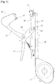
FIG. 1 , the conventional horticultural binder which is one of the prior arts includes: a handle frame 10' having pins 11' protrudingly formed at both sides of the middle part and a stopper 12' disposed at a front end portion; a tape guide 20' attached to a lower face of the handle frame 10' and having a tape case 21'; astapler 30 rotatably mounted inside the handle frame 10' and having staples therein; an arm 40' rotatably mounted to the handle frame 10' and having a clincher 41' opposed to thestapler 30; a head 50' mounted inside the arm 40' to catch and draw out a tape; and a link 60' rotatably mounted to the arm 40' and having ahandle 61' mounted at one side thereof and a hook 62' mounted at the other side. - In the case of the conventional horticultural binder, when a user presses the
handle 61' and tightens the arm 40' once in a state where he or she grasps the tape guide 20' and thehandle 61', a front end of the tape drawn out from the tape case 21' through the tape guide 20' is caught to a hook lever and a pressurizing lever of the head 50' mounted in the arm 40'. In the above state, when the user opens the tape guide 20' and the arm 40', the tape is drawn out in a state where it is caught to the hook lever and the pressurizing lever. After that, when the user winds the tape on the branches of the crops and the props or the guiding strings and pressurizes the tape guide 20' and thehandle 61' with a stronger power to tighten the arm 40', both ends of the tape wound on the branches of the crops and the props or the guiding strings are bound by staples of thestapler 30, and at the same time, cut by a cutter blade mounted on the handle frame 10'. However, the conventional horticultural binder has various problems due to the staples used in the stapler method because thestapler 30 is used to bind both ends of the tape, and hence, there is a demand to continuously study and develop the horticultural binder. - Chinese utility model
CN201341351Y discloses a bundling machine structure comprising a handle frame having pins protrudingly formed on both sides in the middle of the handle frame and a stopper outwardly protruding from a front end portion thereof; a tape guide attached to a lower face of the handle frame and having a tape case; a taper rotatably mounted inside the handle frame; an arm rotatably mounted on the handle frame and having a clincher at an end portion opposed to the taper; a head mounted inside the arm for catching and drawing out a tape; and a link rotatably mounted on the arm and having a handle disposed at one side thereof and a hook disposed at the other side thereof, wherein the taper comprises a binding heating cable which is disposed so as to receive an electric current from a power supply unit; wherein the binding heating cable is opposed to the clincher for binding both ends of a tape, which is interposed between the binding heating cable and the clincher, by heat. - Accordingly, the present invention has been made in an effort to solve the above-mentioned problems occurring in the conventional binder for horticultural use which binds stems and branches to props and guiding strings in order to let garden products or crops grow properly. The conventional binder for horticultural use according to the prior art having the stapler using staples has several problems in that the staples must be continuously supplied for a continuous use of the binder, in that the staples supplied from the stapler are exactly coincided with the staple grooves of the clincher of the arm to properly bind both ends of the tape by the staples, in that the user has to stop work in the case that the staples are fit into the stapler in a bent state or are exhausted, in that the binder cannot catch and cut the tape smoothly, and in that the tape is not securely caught because the front end of the tape is damaged or torn.
- To achieve the above objects, the present invention according to claim 1 provides a binder for horticultural use comprising: a handle frame having pins protrudingly formed on both sides in the middle of the handle frame and a stopper outwardly protruding from a front end portion thereof; a tape guide attached to a lower face of the handle frame and having a tape case; a taper rotatably mounted inside the handle frame; an arm rotatably mounted on the handle frame and having a clincher at an end portion opposed to the taper; a head mounted inside the arm for catching and drawing out a tape; and a link rotatably mounted on the arm and having a handle disposed at one side thereof and a hook disposed at the other side thereof, wherein the taper comprises: a taper frame; and a binding heating cable unit having a binding heating cable which is disposed so as to receive an electric current from a power supply unit; wherein the binding heating cable is opposed to the clincher for binding both ends of a tape, which is interposed between the binding heating cable and the clincher, by heat; the binder for horticultural use being characterized in that: the taper frame has a holder groove disposed at one side thereof; and the taper further comprises a holder to which the binding heating cable unit is detachably attached, the holder being inserted into the holder groove.
- The head of the binder can include: a case having an upper case and a lower case; a hook lever mounted inside the case and fit to a tension spring in such a way as to be operated rotatably; a cam plate mounted inside the case and having a cam hole; a first guide mounted inside the case and having a retainer to which a cam hole and a spring are fit; a second guide mounted inside the case and having a retainer to which a cam hole and a spring are fit; a support mounted inside the case; a rotational lever mounted inside the case and rotated by operation of the first guide and the second guide; and a push lever mounted inside the case and going into and out of the case by operation of the rotational lever.
- The binder for horticultural use according to the present invention can bind both ends of the tape together by heat by partially melting the tape made of synthetic resin material without using staples because using the taper instead of the stapler. Therefore, the binder for horticultural use according to the present invention can prevent the problems of the conventional binder that the staples must be continuously supplied for a continuous use of the binder, that the staples supplied from the stapler are exactly coincided with the staple grooves of the clincher of the arm to properly bind both ends of the tape by the staples, that the user has to stop work in the case that the staples are fit into the stapler in a bent state or are exhausted. Moreover, the binder for horticultural use according to the present invention can firmly bind both ends of the tape together by heat. Furthermore, in the head of the binder for horticultural use, the hook lever is smoothly operated step by step to catch and draw out the tape, and the push lever protrudes outwardly and presses the tape to the cutter blade so as to cut the tape, so that the binder for horticultural use can reduce a damage of the tape and securely catch and draw out the tape through the smooth operation of the hook lever, and can provide a smooth cutting of the tape and enhance durability by preventing a damage and transformation of the push lever while working because the push lever protrudes outwardly from the head and presses the tape to the cutter blade only when the tape is cut.
-
-
FIG. 1 is a side view of a binder for horticultural use according to a prior art. -
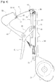
FIGS. 2 to 5 are side view of a binder for horticultural use according to a preferred embodiment of the present invention. -
FIG. 6 is a partially perspective view showing a joined state of a taper and a handle frame of the binder for horticultural use according to the present invention. -
FIGS. 8(a) to 8(c) are partially perspective view of a binding heating cable of the binder for horticultural use according to the present invention. -
FIG. 9 is a partially perspective view showing an operational state of the taper of the binder for horticultural use according to the present invention. -
FIG. 10 is a partially perspective view showing the taper of the binder for horticultural use according to the present invention (in the case that the binding heating cable is disposed). -
FIG. 11 is a partially perspective view showing the operational state of the taper of the binder for horticultural use according to the present invention (in the case that the binding heating cable is disposed). -
FIG. 12 is a side view of the binder for horticultural use according to the present invention (in the case that the binding heating cable is disposed). -
FIG. 13 is a side view showing the operational state of the binder for horticultural use according to the present invention (in the case that the binding heating cable is disposed). -
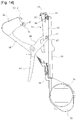
FIG. 14 is a side view of the binder for horticultural use according to the present invention (in the case that a power supply unit is mounted on a tape case). -
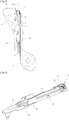
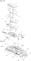
FIG. 15 is an exploded perspective view of a head of the binder for horticultural use according to the present invention. -
FIG. 16 is a perspective view showing an assembled state of the head of the binder for horticultural use according to the present invention. -
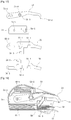
FIG. 17 is a side view showing essential components of the head of the binder for horticultural use according to the present invention. -
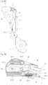
FIGS. 18 and19 are views showing an initially operational state of the head of the binder for horticultural use according to the present invention. -
FIGS. 20 and 21 are views showing the first stage operational state of the head of the binder for horticultural use according to the present invention. -
FIG. 22 is a side view showing the first stage operational state of the binder for horticultural use according to the present invention. -
FIGS. 23 and24 are views showing the second stage operational state of the head of the binder for horticultural use according to the present invention. -
FIG. 25 is a side view showing the second stage operational state of the binder for horticultural use according to the present invention. -
FIGS. 26 and 27 are views showing the third stage operational state of the head of the binder for horticultural use according to the present invention. -
FIG. 28 is a side view showing the third stage operational state of the binder for horticultural use according to the present invention. -
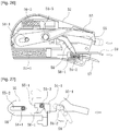
FIG. 29 is a side view of essential parts showing the third stage operational state of the binder for horticultural use according to the present invention. -
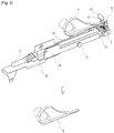
FIGS. 30 and 31 are views showing the fourth stage operational state of the head of the binder for horticultural use according to the present invention. - The present invention relates to a binder for horticultural use, which is to be used to bind stems and branches to props or guiding strings such that a garden or agricultural product can be properly grown. The binder for horticultural use, which is to be used to bind stems and branches to props or guiding strings such that a garden or agricultural product can be properly grown, includes a
handle frame 10, atape guide 20, ataper 31, anarm 40, ahead 50, and alink 60. Thetaper 31 includes: ataper frame 32 to which a cover is attached and which has aholder groove 33 disposed at one side thereof; a bindingheating cable unit 35 having a bindingheating cable 34 which is disposed so as to receive an electric current from apower supply unit 70; and aholder 36 to which the bindingheating cable unit 35 is detachably attached, theholder 36 being inserted into theholder groove 33. Thebinding heating cable 34 is opposed to aclincher 41 for binding both ends of a tape T, which is interposed between thebinding heating cable 34 and theclincher 41, by heat. - Hereinafter, referring to
FIGS. 1 to 31 , the preferred embodiment of the present invention will be described in detail as follows. - Concretely, the
handle frame 10 of the binder for horticultural use according to the present invention includespins 11 protrudingly formed on both sides in the middle of thehandle frame 10 and astopper 12 outwardly protruding from a front end portion thereof. Moreover, thetape guide 20 has atape case 21 disposed at one side thereof, is attached to a lower face of thehandle frame 10, and is disposed in such a fashion that the tape T is released from a tape reel accommodated in thetape case 21 and drawn out through the inside of thetape guide 20. - Furthermore, the
arm 40 has theclincher 41 mounted at an upper end portion opposed to thetaper 31 and a lower end portion of thearm 40 is rotatably mounted on a lower portion of thehandle frame 10. Additionally, thehead 50 is mounted inside an upper part of thearm 40, and a front end portion of thehead 50 is caught and drawn out by a hook lever which is rotatably operated. In addition, thelink 60 is rotatably mounted on thearm 40, and includes: ahandle 61 disposed at one side so that a user can grasp it with the hand; and ahook 62 disposed at the other side joined to thepin 11 of thehandle frame 10. - As shown in
FIG. 3 , when the user grasps thetape guide 20 and thehandle 61 with the hand and pressurizes thehandle 61 once to tighten thearm 40 slightly, the front end of the tape T drawn out from thetape case 21 through thetape guide 20 is caught to the hook lever and a support of thehead 50 mounted on thearm 40, and in the above state, when the user opens thearm 40 while releasing the pressurizing force of thehandle 61, the tape T is drawn out in the state where it is caught to the hook lever and the support of thehead 50. Next, as shown inFIG. 5 , when the user winds the tape T onto branches of crops and props or guiding strings and pressurizes thehandle 61 with a stronger power to tighten thearm 40, both ends of the tape T wound on the branches of the crops and the props or the guiding strings are bound together by heat generated from thetaper 31 while theclincher 41 is pressurized to thetaper 31, and at the same time, a cutter blade C mounted on thehandle frame 10 cuts the tape T. Accordingly, the binder for horticultural use according to the present invention binds the branches of the crops to the props or the guiding strings with the tape T so that the crops grow properly, because the tape T is wound onto the branches of the crops and the props or the guiding strings, both ends of the tape T are bound together by heat generated from thetaper 31 and the tape T is cut by the cutter blade C. - The
taper 31 which is one of essential parts of the present invention includes: ataper frame 32 rotatably mounted inside thehandle frame 10 and having aholder groove 33 disposed at one side; a bindingheating cable unit 35 having abinding heating cable 34 which is disposed so as to receive an electric current from apower supply unit 70; and aholder 36 to which the bindingheating cable unit 35 is detachably attached, theholder 36 being inserted into theholder groove 33. Thebinding heating cable 34 is opposed to theclincher 41 for binding both ends of a tape T, which is interposed between thebinding heating cable 34 and theclincher 41, by heat. - In detail, the binder for horticultural use according to the prior art binds both ends of the tape T winding the branches of the crops and the props or the guiding strings by bending the staples of the
stapler 30 with theclincher 41, however, the binder for horticultural use according to the present invention has thetaper 31 instead of thestapler 30 providing the staples so as to partially melt the tape T made of synthetic resin material by heat to thereby bind both ends of the tape T together without using the staples. In other words, theholder groove 33 formed in one side (in direction that thehead 50 is disposed) of thetaper frame 32 is formed at the position, to which the staples of thestapler 30 of the conventional binder for horticultural use are provided, so as to supply an electric current to the heating unit which supplies not the staples but heat, and theholder 36 is inserted into theholder groove 33 in such a way as to detachably mount the heating unit. - In this instance, it is natural that a
head corresponding unit 63 which has anauxiliary blade 13 and atape leading portion 64 is joined to an outer face of theholder groove 33 of thetaper frame 32 so that a hook 53-2 of the hook lever of thehead 50 surely catches the tape T supplied from thetape leading portion 64 and the cutter blade T which is theauxiliary blade 13 easily cuts the tape T. - Moreover, when an electric current of a predetermined amount is supplied, because the binding
heating cable unit 35 having thebinding heating cable 34 which receives the electric current of a predetermined amount from thepower supply unit 70 has a predetermined resistance, the bindingheating cable unit 35 partially melts the tape T made of synthetic resin material using the heating cable which generates heat, and hence, both ends of the tape T are bound together by a binding force of the synthetic resin material generated from the melted portion. Furthermore, the bindingheating cable unit 35 having thebinding heating cable 34 is detachably attached to theholder 36. Therefore, when electrodes of the bindingheating cable unit 35 are respectively put into the anode and cathode of a power socket disposed on theholder 36, the binder can simply receive electric power from theholder 36, and shows an effect that thebinding heating cable 34 is replaced with a new one by separating the bindingheating cable unit 35 from theholder 36 like a fuse in the case that thebinding heating cable 35 is broken during use (In this instance, it is obvious that those skilled in the art can unite the bindingheating cable unit 35 and theholder 36 on their judgment.). - Accordingly, the binder having the
binding heating cable 34 can solve the problems of the conventional binder using thestapler 30 having the staples, that continuously supplies the staples for a continuous use and that the user must stop work when the staples are fit into thestapler 30 in a bent state or are exhausted. Moreover, because the bind for horticultural use according to the present invention binds both ends of the tape T together by partially melting the tape T made of synthetic resin material not by the staples but by heat, it can use the tape T which is thinner than that of the conventional binder using the staples. - Furthermore, as shown in
FIGS. 8(a) to 8(c) , because thebinding heating cable 34 is formed in a shape of "- - -" or " | | | " and the bound portion of the tape T bound by heat generated from thebinding heating cable 34 is partially melted, both ends of the tape T can be bound together smoothly without regard to volume of the electric current applied to thebinding heating cable 34 or temperature of heat generated from thebinding heating cable 34 due to resistance of thebinding heating cable 34. - Additionally, because the
clincher 41 can apply a pressurizing force of a predetermined amount to both ends of the tape T when thebinding heating cable 34 is located just on the corresponding face of thebinding heating cable 34, it can solve the problem of the conventional binder that the staples can bind both ends of the tape T properly only when the staples supplied from thestapler 30 and the staple grooves of theclincher 41 of the arm are exactly coincided with each other. In connection with the above, theclincher 41 according to the present invention partially accommodates the both ends of the tape T and thebinding heating cable 34 corresponding in a direction of theclincher 41 and being pressurized by theclincher 41 when pressurizing thehandle 61 to tighten thearm 40 because theclincher 41 has an elastic force of a predetermined amount at the face opposed to thebinding heating cable 34 of thetaper 31, and may further include a nonflammableelastic body 42 with minor transformation and damage even by heat generated from thebinding heating cable 34. - In addition, besides the binding
heating cable unit 35 having thebinding heating cable 34 for thermally binding both ends of the tape T, which are introduced between thebinding heating cable 34 and theclincher 41 and are wound on the branches of the crops and the props and the guiding strings, as shown inFIGS. 10 to 13 , instead of the cutter blade C disposed at the end of thehandle frame 10, the binder further includes a cuttingheating cable unit 35' having a cutting heating cable 34' which receives an electric current of a predetermined amount from thepower supply unit 70. In this instance, theholder 36 can detachably hold the cuttingheating cable unit 35' as well as the bindingheating cable unit 35, and theclincher 41 is also opposed to the cutting heating cable 34' so as to cut both ends of the tape T introduced between the cutting heating cable 34' and theclincher 41. In other words, electrodes of the cuttingheating cable unit 35' are respectively put into the anode and cathode of the power socket of theholder 36 for connecting the electrodes of the bindingheating cable unit 35 and the electrodes of the cuttingheating cable unit 35', so that the binder can easily receive electric power from theholder 36, and the cutting heating cable 34' is replaced with a new one by separating the cuttingheating cable unit 35' from theholder 36 in the case that the cuttingheating cable 35' is broken during use. In comparison with the conventional binder which cuts both ends of the tape T using the cutter blade C, the binder according to the present invention needs a smaller power than the conventional binder when the user grasps and pressurizes thehandle 61. - In relation with the above, the
power supply unit 70 according to the present invention supplies the electric current of a predetermined amount to theholder 36 to which the electrodes of the bindingheating cable unit 35 having thebinding heating cable 34 or the cuttingheating cable unit 35' having the cutting heating cable 34' in order to supply electric power of the predetermined amount to thebinding heating cable 34 or the cutting heating cable 34' . In this instance, the supplied electric current may be supplied through any part of the binder for horticultural use according to the present invention, but it is preferable that an electric wire is disposed inside thetaper frame 32 so that electric current is safely supplied to the holder from thepower supply unit 70 which is disposed outside the binder for horticultural use according to the present invention. Moreover, it is preferable that thepower supply unit 70 disposed outside the binder uses a primary cell or a secondary cell so that the user can work smoothly and theelectric wire 71 is elongated as long as the user can hold it. As shown inFIG. 14 , thepower supply unit 70 may be disposed at one side of thetape case 21 in such a way as to be formed integrally with the binder for horticultural use, and hence, it can enhance workability through the simplifiedpower supply unit 70. - Furthermore, in order to control the amount and the supply period of time of the electric current supplied to the
binding heating cable 34 or the cutting heating cable 34', a control module (not shown in the drawings) is mounted at a position of thepower supply unit 70 or the binder for horticultural use, and then, the binder for horticultural use according to the present invention can supply a proper amount of electric current to thebinding heating cable 34 for a proper period of time so as to firmly bind the tape T and can supply a proper amount of electric current to the cutting heating cable 34' for a proper period of time so as to cut a predetermined position of the tape T bound by thebinding heating cable 34. - In this instance, in order to prevent that both ends of the tape T are bound weakly by the
binding heating cable 34 or imperfectly cut by the cutting heating cable 34' when the electric voltage stored in the primary cell or the secondary cell is decreased due to a continuous use of the binder for horticultural use, the control module can control the electric voltage. - The binder for horticultural use according to the present invention may further include an
operation sensor 37 which is mounted between thetaper frame 32 and thehandle frame 10 to control supply of the electric current to thebinding heating cable 34 or the cutting heating cable 34'. Concretely, electric current is excessively consumed and the lifespan of thebinding heating cable 34 or the cutting heating cable 34' may be reduced if the electric current supplied from thepower supply unit 70 is always supplied to thebinding heating cable 34 or the cutting heating cable 34' during work. Therefore, it is preferable that theoperation sensor 37 for controlling the supply of the electric current from thepower supply unit 70 is disposed in link with any part of the binder. In the binder for horticultural use according to the present invention, theoperation sensor 37 is interposed between thetaper frame 32 and thehandle frame 10 so as to be operated by the user's pressing force applied to thehandle 61 to bind both ends of the tape T together. - Additionally, as shown in
FIG. 7 , the binder may further include anelastic member 38 disposed between thetaper frame 32 and thehandle frame 10. Theelastic member 38 buffs some of the user's pressing force applied to thehandle 61 to bind both ends of the tape T together, such that it can prevent theclincher 41 and the bindingheating cable unit 35 or theclincher 41 and the cuttingheating cable unit 35' from being damaged due to an excessive pressing force and that it makes theoperation sensor 37 be operated by not only a sensor-operation method but also a switching method in the case that theoperation sensor 37 is disposed between thetaper frame 32 and thehandle frame 10. - In addition, the
head 50 is embedded in an upper portion of thearm 40, and thehook lever 53 is rotatably operated to catch and draw out the front end portion of the tape T. Moreover, thelink 60 is rotatably mounted on thearm 40, has thehandle 61 disposed at one side thereof for allowing the user to grasp it with then hand and thehook 62 disposed at the other side so as to be joined to thepin 11 of thehandle frame 10. - In the binder for horticultural use having the above structure, when the user grasps the
tape guide 20 and thehandle 61 with the hand and pressurizes thehandle 61 to tighten thearm 40 slightly once, the front end of the tape T drawn out from thetape case 21 through thetape guide 20 is caught to thehook lever 53 and thesupport 57 of thehead 50 mounted on thearm 40, and in this condition, when the user releases the pressurizing force to thehandle 61 to open thearm 40, the tape T is drawn out in the state where the tape T is caught to thehook lever 53 and thesupport 57 of thehead 50. After that, when the user winds the tape T onto the branches of the crops and the props or the guiding strings and pressurizes thehandle 61 with a stronger power to tighten thearm 40, while theclincher 41 is pressed to thebinding heating cable 34, both ends of the tape T wound on the branches of the crops and the props or the guiding strings are bound together by heat, and at the same time, the tape T is cut by the cutter blade C mounted on thehandle frame 10. (In the case that the cutting heating cable 34' is mounted instead of the cutter blade, it is obvious that the tape is cut by the cutting heating cable, and hereinafter, 'cutter blade' means that it contains the cutting heating cable.) - Accordingly, after the tape T is wound on the branches of the crops and the props or the guiding strings, the tape T is bound by the
binding heating cable 34 and theclincher 41 and is cut by the cutter blade C, and hence, the branches of the crops are bound to the props or the guiding strings by the tape T so that the crops can grow properly. - Next, essential parts of the
head 50 of the binder for horticultural use according to the present invention will be described. Thehead 50 of the binder includes: a case having anupper case 51 and alower case 52; ahook lever 53 mounted inside the case and fit to a tension spring 53-5 in such a way as to be operated rotatably; acam plate 54 mounted inside the case and having a cam hole 54-1; afirst guide 55 mounted inside the case and having a retainer 55-3 to which a cam hole 55-1 and a spring 55-5 are fit; asecond guide 56 mounted inside the case and having a retainer 56-3 to which a cam hole 56-1 and a spring 56-5 are fit; asupport 57 mounted inside the case; arotational lever 58 mounted inside the case and rotated by operation of thefirst guide 55 and thesecond guide 56; and apush lever 59 mounted inside the case and going into and out of the case by operation of therotational lever 58. - As shown in
FIGS. 15 to 17 , the case of thehead 50 has theupper case 51 and thelower case 52, a pin 51-1 is fit to theupper case 51 and thelower case 52, and thehook lever 53, thecam plate 54, thefirst guide 55, thesecond guide 56, thesupport 57, therotational lever 58 and thepush lever 59 are mounted inside theupper case 51 and thelower case 52. - The
hook lever 53 includes: an elongated hole 53-1, which is formed at one side thereof, and, to which the pin 51-1 is fit; a hook 53-2 formed at a front end of the opposite side; an operation pin 53-3 and a fixing shaft 53-4 formed symmetrically to each other at the central portion; and the tension spring 53-5 fit onto the fixing shaft 53-4. - Moreover, the
cam plate 54 is arranged below thehook lever 53, and includes: the cam hole 54-1 formed at one side in a shape of "", to which the operation pin 53-3 is fit; and a joining hole 54-2 formed at the other side, to which the pin 51-1 is fit.
- Furthermore, the
first guide 55 is arranged below thecam plate 54, and includes: the cam hole 55-1 formed at the central portion thereof in a shape of "", to which the operation pin 53-3 of the
hook lever 53 is fit; an elongated hole 55-2 formed in one side thereof, to which the pin 51-1 is fit; the retainer 55-3 formed below the cam hole 55-1 and supported by the spring 55-5 fit thereto; and a recess 55-4 formed in the opposite side of the elongated hole 55-2. - Additionally, the
second guide 56 is arranged below thefirst guide 55, and includes: the cam hole 56-1 formed at the central portion thereof in a shape of "", to which the operation pin 53-3 of the
hook lever 53 is fit; an elongated hole 56-2 formed in one side thereof, to which the pin 51-1 is fit; the retainer 56-3 formed above the cam hole 56-1 and supported by the spring 56-5 fit thereto; and a recess 56-4 formed in the opposite side of the elongated hole 56-2. - Moreover, the
support 57 serves to catch the tape T by engaging with thehook lever 53, and is mounted and fixed inside the front end portion of the case in such a way as to be opposed to thestopper 12 of thehandle frame 10 and thebinding heating cable 34. - Furthermore, the
rotational lever 58 is rotated according to the operations of thefirst guide 55 and thesecond guide 56, and includes: a first rotational pin 58-1 formed at the bottom face of the central portion thereof and rotatably assembled to the case; and a second rotational pin 58-2 formed at the bottom face of one side in such a way as to be inserted into the recesses 55-4 and 56-4 of thefirst guide 55 and thesecond guide 56. - Additionally, the
push lever 59 serves to go into and out of the case according to the operation of therotational lever 58, and includes the retainer 59-1 movably fit between the front end portion of the case and the upper portion of thesupport 57 and supported by the spring 59-2 fit at the rear end portion thereof. - Now, an assembling process of the
head 50 having the above structure will be described. First, the pin 51-1 is fit into the elongated hole 56-2 in such a fashion that thesecond guide 56 is mounted inside thelower case 52, and thefirst guide 55 is put on thesecond guide 56 and the pin 51-1 is fit into the elongated hole 55-2. After that, the springs 55-5 and 56-5 are respectively fit to the retainers 55-3 and 56-3 of thefirst guide 55 and thesecond guide 56 so as to elastically support the retainers 55-3 and 56-3, and then, therotational lever 58 is fit to thelower case 52 in such a fashion that the rotational pin 58-2 is inserted into the recesses 55-4 and 56-4 of thefirst guide 55 and thesecond guide 56. - Next, the
cam plate 54 is put on thefirst guide 55 and the pin 51-1 is inserted into the joining hole 54-2, and thehook lever 53 is elastically mounted on thecam plate 54 in such a fashion that the pin 51-1 is fit into the elongated hole 53-1, the operation pin 53-3 is fit into the cam holes 54-1, 55-1 and 56-1 formed in thecam plate 54, thefirst guide 55 and thesecond guide 56, and the tension spring 53-5 is fit to the fixing shaft 53-4. - Moreover, the
support 57 is mounted below the front end portions of theupper case 51 and thelower case 52, and then, thepush lever 59 is movably fit on thesupport 57 in such a way as to receive the elastic force of the spring 59-2. - Now, an operation process of the
head 50 will be described. First, in the initial state of thehead 50, thearm 40 is in an opened state, and as shown inFIGS. 18 and19 , the operation pin 53-3 of thehook lever 53 is caught to an upper stepped jaw of the cam hole 55-1 of thefirst guide 55, so that thehook lever 53 is in a upwardly rotated state. - In the above initial state, when the user pressurizes the
handle 61 of the binder to slightly tighten thearm 40 once, as shown inFIGS. 20 to 22 , thefirst guide 55 and thesecond guide 56 are pressurized to thestopper 12 of thehandle frame 10 and pushed backward, and then, the operation pin 53-3 of thehook lever 53 lowers and is first rotated while being caught to a lower stepped jaw of the cam hole 56-1 of thesecond guide 56. - Next, when the user releases the pressurizing force to the
handle 61, as shown inFIGS. 23 to 25 , the pressurizing force is disappeared because thestopper 12 of thehandle frame 10 is spaced away from thefirst guide 55 and thesecond guide 56, and hence, thefirst guide 55 and thesecond guide 56 are pushed forward by the elastic force of the springs 55-5 and 56-5. Then, the operation pin 53-3 of thehook lever 53 lowers from the cam holes 55-1 and 56-1 of thefirst guide 55 and thesecond guide 56 to a lower space. When thehook lever 53 is second rotated, the hook 53-2 sticks the front end portion of the tape T so that the tape T is caught to thesupport 57. After that, because thearm 40 is opened to drag the tape T, the tape T is drawn out from thetape case 21 through thetape guide 20. - Next, as shown in
FIGS. 26 to 29 , when the user winds the drawn tape T onto the branches of the crops and the props or the guiding strings and pressurizes thehandle 61 of the binder with a stronger power to tighten thearm 40, theclincher 41 is pressurized to thebinding heating cable 34 and both ends of the tape T wound on the branches of the crops and the props or the guiding strings are bound together by heat. - Furthermore, the
first guide 55 and thesecond guide 56 are pressurized to thestopper 12 of thehandle frame 10 and pushed backward, and hence, the operation pin 53-3 of thehook lever 53 is ascended from the cam hole 54-1 of thecam plate 54 to the upper stepped jaw. Then, thehook lever 53 is separated from the tape T while rotating upward, and at the same time, therotational lever 58 is rotated by the operation of thefirst guide 55 and thesecond guide 56 to thereby push out thepush lever 59, and then, the front end portion of thepush lever 59 presses the tape T to the cutter blade C to thereby cut the tape T. - Next, when the user releases the pressurizing power to the
handle 61, while thearm 40 is opened, as shown inFIGS. 30 and 31 , because thestopper 12 is separated from thefirst guide 55 and thesecond guide 56 and the pressurizing power is disappeared, thefirst guide 55 and thesecond guide 56 is pushed forward while receiving the elastic force of the springs 55-5 and 56-5, and then, the operation pin 53-3 of thehook lever 53 is caught to the upper stepped jaw of the cam hole 55-1 of thefirst guide 55 and is positioned in the initial state. At the same time, therotational lever 58 pulls thepush lever 59 to the inside of the case so that thepush lever 59 is located in the initial state while being rotated by the operation of thefirst guide 55 and thesecond guide 56 so as to be located in the initial state. - Accordingly, the binder for horticultural use according to the present invention can reduce a damage of the tape and securely catch and draw out the tape through a smooth operation of the hook lever because the hook lever is smoothly operated in the head step by step to catch and draw out the tape, and provide a smooth cutting of the tape and enhance durability by preventing a damage and transformation of the push lever while working because the push lever protrudes outwardly from the head and presses the tape to the cutter blade only when the tape is cut.
- While the present invention has been particularly shown and described with reference to exemplary embodiment thereof, it will be understood by those of ordinary skill in the art that various changes in form and details may be made therein without departing from the scope of the present invention as defined by the following claims.
| 10: handle frame | 11: pin | |
| 12: stopper | 13: auxiliary blade | |
| 20: tape guide | 21: tape case | |
| 31: taper | 32: taper frame | |
| 33: holder groove | 34: binding heating cable | |
| 34': binding heating cable | ||
| 35: binding |
||
| 35': cutting heating cable unit | ||
| 36: holder | 37: operation sensor | |
| 38: elastic member | 40: arm | |
| 41: clincher | 42: nonflammable elastic body | |
| 50: head | 51: upper case | 52: lower case |
| 53: hook lever | 54: cam plate | |
| 55: first guide | 56: second guide | |
| 57: support | 58: rotational lever | |
| 59: push lever | 60: link | |
| 61: handle | 62: hook | |
| 63: | 64: | |
| 70: power supply unit | 71: electric wire | |
| C: cutter blade | T: tape | |
Claims (11)
- A binder for horticultural use comprising: a handle frame (10) having pins (11) protrudingly formed on both sides in the middle of the handle frame (10) and a stopper (12) outwardly protruding from a front end portion thereof; a tape guide (20) attached to a lower face of the handle frame (10) and having a tape case (21); a taper (31) rotatably mounted inside the handle frame (10); an arm (40) rotatably mounted on the handle frame (10) and having a clincher (41) at an end portion opposed to the taper (31); a head (50) mounted inside the arm (40) for catching and drawing out a tape (T); and a link (60) rotatably mounted on the arm (40) and having a handle (61) disposed at one side thereof and a hook (62) disposed at the other side thereof,
wherein the taper (31) comprises:a taper frame (32); anda binding heating cable unit (35) having a binding heating cable (34) which is disposed so as to receive an electric current from a power supply unit (70);wherein the binding heating cable (34) is opposed to the clincher (41) for binding both ends of a tape (T), which is interposed between the binding heating cable (34) and the clincher (41), by heat;the binder for horticultural use being characterized in that:the taper frame (32) has a holder groove (33) disposed at one side thereof; andthe taper (31) further comprises a holder (36) to which the binding heating cable unit (35) is detachably attached, the holder (36) being inserted into the holder groove (33). - The binder according to claim 1, wherein the handle frame (10) does not have a cutter blade (C), the taper (31) further comprises a cutting heating cable unit (35') having a cutting heating cable (34') receiving an electric current of a predetermined amount from the power supply unit (70), the holder (36) can detachably mount not only the binding heating cable unit (35) but also the cutting heating cable unit (35'), and the clincher (41) is also opposed to the cutting heat cable (34') to cut both ends of the tape (T), which is interposed between the cutting heating cable (34') and the clincher (41), by heat.
- The binder according to claim 1 or 2, wherein the clincher (41) further comprises a nonflammable elastic body (42).
- The binder according to claim 1, wherein the power supply unit (70) is disposed at one side of the tape case (21).
- The binder according to claim 1 or 4, wherein the power supply unit (70) comprises a control module for controlling an amount and a supply period of time of the supplied electric current.
- The binder according to claim 1, wherein the taper frame (32) further comprises an operation sensor (37) disposed between the taper frame (32) and the handle frame (10).
- The binder according to claim 1, wherein the taper frame (32) further comprises an elastic member (38) disposed between the taper frame (32) and the handle frame (10).
- The binder according to claim 1, wherein the head (50) comprises:a case having an upper case (51) and a lower case (52) and a pin (51-1) fit to the upper case (51) and the lower case (52);a hook lever (53) mounted inside the case, the hook lever (53) having an elongated hole (53-1) formed in one side to which the pin (51-1) is inserted, a hook (53-2) formed in a front end of the other side, an operation pin (53-3) and a fixing shaft (53-4) formed at the central portion thereof, and a tension spring (53-5) fit onto the operation pin and the fixing shaft;a cam plate (54) mounted inside the case and arranged below the hook lever (53), the cam plate having a cam hole (54-1) formed in one side thereof and a joining hole (54-2) formed in the other side to which the pin (51-1) is inserted;a first guide (55) mounted inside the case and arranged below the cam plate (54), the first guide (55) having a cam hole (55-1) formed at the central portion thereof, an elongated hole (55-2) formed at one side thereof to which the pin (51-1) is inserted, a retainer (55-3) to which a spring (55-5) is fit, and a recess (55-4);a second guide (56) mounted inside the case and arranged below the first guide (55), the second guide (56) having a cam hole (56-1) formed at the central portion thereof, an elongated hole (56-2) formed at one side thereof to which the pin (51-1) is inserted, a retainer (56-3) to which a spring (56-5) is fit, and a recess (56-4);a support (57) mounted inside a front end portion of the case;a rotational lever (58) mounted inside the case, the rotational lever (58) having a first rotational pin (58-1) formed at the bottom face of the central portion thereof and rotatably assembled to the case and a second rotational pin (58-2) rotating by operation of the first guide (55) and the second guide (56), the rotational lever (58) being rotated by the first and second rotational pins; anda push lever (59) movably fit and mounted from the front end portion of the case to an upper portion of the support.
- The binder according to claim 8, wherein the rotational lever (58) is rotatably operated by the rotational pin (58-2) which is inserted into the recesses (55-4) (56-4) respectively formed in the first guide (55) and the second guide (56).
- The binder according to claim 8, wherein the push lever (59) has the retainer (59-1) formed at a rear end portion thereof and supported by the spring (59-2) fit thereto, so that the push lever (59) goes into and out of the front end portion of the case by operation of the rotational lever (58).
- The binder according to claim 8, wherein operation pin (53-3) formed on the hook lever (53) is operably fit into the cam holes (54-1) (55-1) (56-1) respectively formed in the cam plate (54), the first guide (55), and the second guide (56).
Applications Claiming Priority (2)
| Application Number | Priority Date | Filing Date | Title |
|---|---|---|---|
| KR1020100093627A KR101027960B1 (en) | 2010-09-28 | 2010-09-28 | Gardening binding machine |
| PCT/KR2011/004542 WO2012043968A1 (en) | 2010-09-28 | 2011-06-22 | Binder for horticultural use |
Publications (3)
| Publication Number | Publication Date |
|---|---|
| EP2622957A1 EP2622957A1 (en) | 2013-08-07 |
| EP2622957A4 EP2622957A4 (en) | 2017-11-01 |
| EP2622957B1 true EP2622957B1 (en) | 2019-11-20 |
Family
ID=44049832
Family Applications (1)
| Application Number | Title | Priority Date | Filing Date |
|---|---|---|---|
| EP11829474.3A Active EP2622957B1 (en) | 2010-09-28 | 2011-06-22 | Binder for horticultural use |
Country Status (8)
| Country | Link |
|---|---|
| US (1) | US9060471B2 (en) |
| EP (1) | EP2622957B1 (en) |
| JP (1) | JP5530033B2 (en) |
| KR (1) | KR101027960B1 (en) |
| CN (1) | CN103025148B (en) |
| BR (1) | BR112013004025A2 (en) |
| ES (1) | ES2770574T3 (en) |
| WO (1) | WO2012043968A1 (en) |
Families Citing this family (29)
| Publication number | Priority date | Publication date | Assignee | Title |
|---|---|---|---|---|
| KR101347856B1 (en) * | 2011-12-26 | 2014-01-07 | 서해영 | Binding machine for gardening |
| KR101347857B1 (en) * | 2011-12-30 | 2014-01-07 | 서해영 | Binding machine of gardening with structure for preventing unwind |
| KR101509623B1 (en) * | 2013-11-12 | 2015-04-07 | 조남선 | A binding machine for gardening |
| US9736997B2 (en) * | 2014-01-02 | 2017-08-22 | Nam Sun CHO | Binding machine for agriculture |
| JP6285744B2 (en) * | 2014-02-21 | 2018-02-28 | ニチバン株式会社 | Tape presser mechanism in bundling device |
| EP3133913B1 (en) | 2014-04-24 | 2020-02-26 | Cruzzolin, Andrea | Apparatus and corresponding operative method to automatically bind at least two elements to each other |
| CN105076106A (en) * | 2014-05-20 | 2015-11-25 | 黄茗清 | Method for killing vine |
| CN104170697A (en) * | 2014-08-18 | 2014-12-03 | 池昭瑞 | Novel fruit and vegetable branch binding machine |
| JP6677091B2 (en) * | 2016-06-15 | 2020-04-08 | マックス株式会社 | Gardening binding machine |
| JP1572313S (en) * | 2016-06-15 | 2017-03-27 | ||
| JP6677089B2 (en) * | 2016-06-15 | 2020-04-08 | マックス株式会社 | Gardening binding machine |
| JP6638568B2 (en) * | 2016-06-15 | 2020-01-29 | マックス株式会社 | Gardening binding machine |
| KR101789433B1 (en) * | 2016-07-14 | 2017-10-23 | 장병호 | Support frame for agriculture plantlet and manufacturing method of bracket for the support frame |
| CN106818391A (en) * | 2017-02-21 | 2017-06-13 | 方培锵 | One kind ties up a machine |
| CN107962524A (en) * | 2017-12-07 | 2018-04-27 | 国网山东省电力公司烟台供电公司 | A kind of reflective tape reinforces specific purpose tool |
| KR101982706B1 (en) * | 2018-01-22 | 2019-05-27 | 조남선 | A binding machine for gardening |
| CN110337941B (en) * | 2019-07-08 | 2021-05-25 | 丰县领发农机有限公司 | Agricultural is grown seedlings and is binded ware |
| JP7324400B2 (en) * | 2019-08-23 | 2023-08-10 | マックス株式会社 | binding machine |
| CN111030667B (en) * | 2019-12-23 | 2024-12-20 | 山东农业大学 | Multifunctional mechanical switch for automatic grape vine binding machine and its use method |
| KR102299513B1 (en) | 2019-12-30 | 2021-09-07 | 서해영 | Binding Machine for gardening |
| KR102527806B1 (en) | 2020-10-22 | 2023-05-02 | 서해영 | Heat fusion-type binding machine and method thereof for gardening |
| JP1695943S (en) | 2020-11-30 | 2021-09-27 | ||
| KR102521001B1 (en) | 2020-12-11 | 2023-04-12 | 서해영 | Binding machine for gardening |
| KR102534219B1 (en) | 2020-12-17 | 2023-05-18 | 서해영 | Electric bindidn machine for gardening |
| KR20220087287A (en) | 2020-12-17 | 2022-06-24 | 서해영 | Binding machine for gardening |
| KR102717151B1 (en) | 2021-04-26 | 2024-10-15 | 서해영 | Binding machine for gardening |
| CN116918600A (en) * | 2022-04-01 | 2023-10-24 | 深圳市农科创网络有限公司 | Electric branch binding machine and branch binding method |
| ES2957737B2 (en) * | 2022-06-17 | 2024-06-03 | Desarrollos Especiales De Sist De Anclaje S A | TYING TOOL |
| KR20240161283A (en) | 2023-05-04 | 2024-11-12 | 주식회사 우바툴스 | Automatic system heat fusion-type binding machine and method thereof for gardening |
Family Cites Families (20)
| Publication number | Priority date | Publication date | Assignee | Title |
|---|---|---|---|---|
| US3368323A (en) * | 1964-10-12 | 1968-02-13 | Fmc Corp | Strap sealing method and apparatus |
| GB1107904A (en) * | 1964-12-04 | 1968-03-27 | Akio Nakano | A thermo-plastic tape or band bonding machine |
| US3755045A (en) * | 1971-05-07 | 1973-08-28 | M Takami | Packing tape binding machine |
| US3944460A (en) * | 1972-12-14 | 1976-03-16 | Interlake, Inc. | Combination strapping tool for plastic strap |
| US4063985A (en) * | 1976-06-30 | 1977-12-20 | Interlake, Inc. | Heat-sealing strapping tool and temperature regulator therefor |
| CH665604A5 (en) * | 1985-01-23 | 1988-05-31 | Strapex Ag | TENSIONING AND LOCKING DEVICE FOR PLASTIC TAPE. |
| US4945674A (en) * | 1990-02-08 | 1990-08-07 | Alexandrian Karen V | Appliance for tying up plants |
| US5858164A (en) * | 1997-06-18 | 1999-01-12 | Midwest Industrial Packaging, Inc. | Apparatus for heat sealing plastic strapping |
| US5863378A (en) * | 1997-06-18 | 1999-01-26 | Midwest Industrial Packaging, Inc. | Apparatus for heat sealing plastic strapping |
| CN2374453Y (en) * | 1999-04-14 | 2000-04-19 | 吴长生 | Automatic bander |
| KR100347635B1 (en) * | 1999-06-04 | 2002-08-07 | 조남선 | A binding machine for gardening |
| CN2378293Y (en) * | 1999-06-21 | 2000-05-17 | 霍劲汉 | Electric soldering tongs for bundling without buckling |
| AU732515B2 (en) * | 1999-07-20 | 2001-04-26 | Nam-Sun Jho | A binding machine for gardening |
| CN1239070C (en) | 2001-07-11 | 2006-02-01 | 美克司公司 | Binding machine for gardening |
| JP2006050913A (en) * | 2004-08-10 | 2006-02-23 | Omura Kogyo Kk | Binding device |
| EP1840031A1 (en) * | 2004-12-20 | 2007-10-03 | Aglis Co., Ltd. | Binding device and binding method for horticulture |
| JP2007117055A (en) * | 2005-10-31 | 2007-05-17 | Max Co Ltd | Mechanism of restoring slack of binding tape in gardening binder |
| JP2008072928A (en) * | 2006-09-20 | 2008-04-03 | Nagashima Junichi | Binding machine |
| KR100779500B1 (en) | 2007-03-05 | 2007-11-28 | 조남선 | Gardening binding machine |
| CN201341351Y (en) * | 2008-12-12 | 2009-11-11 | 金翔发有限公司 | Improved bundler structure |
-
2010
- 2010-09-28 KR KR1020100093627A patent/KR101027960B1/en active Active
-
2011
- 2011-06-22 ES ES11829474T patent/ES2770574T3/en active Active
- 2011-06-22 JP JP2013523078A patent/JP5530033B2/en not_active Expired - Fee Related
- 2011-06-22 BR BR112013004025A patent/BR112013004025A2/en not_active Application Discontinuation
- 2011-06-22 US US13/813,395 patent/US9060471B2/en active Active
- 2011-06-22 CN CN201180036807.5A patent/CN103025148B/en not_active Expired - Fee Related
- 2011-06-22 EP EP11829474.3A patent/EP2622957B1/en active Active
- 2011-06-22 WO PCT/KR2011/004542 patent/WO2012043968A1/en not_active Ceased
Non-Patent Citations (1)
| Title |
|---|
| None * |
Also Published As
| Publication number | Publication date |
|---|---|
| JP2013538049A (en) | 2013-10-10 |
| BR112013004025A2 (en) | 2016-06-28 |
| EP2622957A4 (en) | 2017-11-01 |
| JP5530033B2 (en) | 2014-06-25 |
| KR101027960B1 (en) | 2011-04-13 |
| WO2012043968A1 (en) | 2012-04-05 |
| ES2770574T3 (en) | 2020-07-02 |
| EP2622957A1 (en) | 2013-08-07 |
| US20130125461A1 (en) | 2013-05-23 |
| CN103025148A (en) | 2013-04-03 |
| US9060471B2 (en) | 2015-06-23 |
| CN103025148B (en) | 2014-06-18 |
Similar Documents
| Publication | Publication Date | Title |
|---|---|---|
| EP2622957A1 (en) | Binder for horticultural use | |
| KR101347857B1 (en) | Binding machine of gardening with structure for preventing unwind | |
| CN109964696B (en) | Binding machine for gardening | |
| CN205455006U (en) | Vine binding machine | |
| JP2021031124A (en) | Binding machine | |
| JP2007117055A (en) | Mechanism of restoring slack of binding tape in gardening binder | |
| JP3467684B2 (en) | Gardening binding machine | |
| KR101347856B1 (en) | Binding machine for gardening | |
| CN206821494U (en) | Tendril strapper | |
| KR102521001B1 (en) | Binding machine for gardening | |
| EP3292752A1 (en) | Binding machine for gardening | |
| KR102717151B1 (en) | Binding machine for gardening | |
| CN201821712U (en) | Tape tool | |
| CN216219051U (en) | Tie up branch machine head assembly and tie up branch machine | |
| CN214608274U (en) | Vegetable binding machine | |
| KR100990852B1 (en) | Garden taping machine head | |
| KR102888615B1 (en) | Binding machine | |
| KR102299513B1 (en) | Binding Machine for gardening | |
| CN217038034U (en) | Ytterbium pressing strip seedling growing and twisting pliers | |
| CN216982780U (en) | Branch binding machine and binding nail | |
| KR101098388B1 (en) | Tape Guide of Gardening Strapping Machine | |
| KR20220087287A (en) | Binding machine for gardening | |
| US20230276745A1 (en) | Thermally bonding type horticultural binder and control method therefor | |
| CN216775660U (en) | Bundle equipment based on gardens ribbon | |
| CN209234437U (en) | A kind of planting fast branching device |
Legal Events
| Date | Code | Title | Description |
|---|---|---|---|
| PUAI | Public reference made under article 153(3) epc to a published international application that has entered the european phase |
Free format text: ORIGINAL CODE: 0009012 |
|
| 17P | Request for examination filed |
Effective date: 20130426 |
|
| AK | Designated contracting states |
Kind code of ref document: A1 Designated state(s): AL AT BE BG CH CY CZ DE DK EE ES FI FR GB GR HR HU IE IS IT LI LT LU LV MC MK MT NL NO PL PT RO RS SE SI SK SM TR |
|
| DAX | Request for extension of the european patent (deleted) | ||
| RA4 | Supplementary search report drawn up and despatched (corrected) |
Effective date: 20170928 |
|
| RIC1 | Information provided on ipc code assigned before grant |
Ipc: A01G 17/08 20060101AFI20170922BHEP |
|
| STAA | Information on the status of an ep patent application or granted ep patent |
Free format text: STATUS: EXAMINATION IS IN PROGRESS |
|
| 17Q | First examination report despatched |
Effective date: 20181106 |
|
| GRAP | Despatch of communication of intention to grant a patent |
Free format text: ORIGINAL CODE: EPIDOSNIGR1 |
|
| STAA | Information on the status of an ep patent application or granted ep patent |
Free format text: STATUS: GRANT OF PATENT IS INTENDED |
|
| INTG | Intention to grant announced |
Effective date: 20190611 |
|
| GRAS | Grant fee paid |
Free format text: ORIGINAL CODE: EPIDOSNIGR3 |
|
| GRAA | (expected) grant |
Free format text: ORIGINAL CODE: 0009210 |
|
| STAA | Information on the status of an ep patent application or granted ep patent |
Free format text: STATUS: THE PATENT HAS BEEN GRANTED |
|
| AK | Designated contracting states |
Kind code of ref document: B1 Designated state(s): AL AT BE BG CH CY CZ DE DK EE ES FI FR GB GR HR HU IE IS IT LI LT LU LV MC MK MT NL NO PL PT RO RS SE SI SK SM TR |
|
| REG | Reference to a national code |
Ref country code: GB Ref legal event code: FG4D |
|
| REG | Reference to a national code |
Ref country code: CH Ref legal event code: EP |
|
| REG | Reference to a national code |
Ref country code: IE Ref legal event code: FG4D |
|
| REG | Reference to a national code |
Ref country code: DE Ref legal event code: R096 Ref document number: 602011063547 Country of ref document: DE |
|
| REG | Reference to a national code |
Ref country code: AT Ref legal event code: REF Ref document number: 1203101 Country of ref document: AT Kind code of ref document: T Effective date: 20191215 |
|
| REG | Reference to a national code |
Ref country code: NL Ref legal event code: MP Effective date: 20191120 |
|
| REG | Reference to a national code |
Ref country code: LT Ref legal event code: MG4D |
|
| PG25 | Lapsed in a contracting state [announced via postgrant information from national office to epo] |
Ref country code: NO Free format text: LAPSE BECAUSE OF FAILURE TO SUBMIT A TRANSLATION OF THE DESCRIPTION OR TO PAY THE FEE WITHIN THE PRESCRIBED TIME-LIMIT Effective date: 20200220 Ref country code: BG Free format text: LAPSE BECAUSE OF FAILURE TO SUBMIT A TRANSLATION OF THE DESCRIPTION OR TO PAY THE FEE WITHIN THE PRESCRIBED TIME-LIMIT Effective date: 20200220 Ref country code: GR Free format text: LAPSE BECAUSE OF FAILURE TO SUBMIT A TRANSLATION OF THE DESCRIPTION OR TO PAY THE FEE WITHIN THE PRESCRIBED TIME-LIMIT Effective date: 20200221 Ref country code: FI Free format text: LAPSE BECAUSE OF FAILURE TO SUBMIT A TRANSLATION OF THE DESCRIPTION OR TO PAY THE FEE WITHIN THE PRESCRIBED TIME-LIMIT Effective date: 20191120 Ref country code: LT Free format text: LAPSE BECAUSE OF FAILURE TO SUBMIT A TRANSLATION OF THE DESCRIPTION OR TO PAY THE FEE WITHIN THE PRESCRIBED TIME-LIMIT Effective date: 20191120 Ref country code: SE Free format text: LAPSE BECAUSE OF FAILURE TO SUBMIT A TRANSLATION OF THE DESCRIPTION OR TO PAY THE FEE WITHIN THE PRESCRIBED TIME-LIMIT Effective date: 20191120 Ref country code: LV Free format text: LAPSE BECAUSE OF FAILURE TO SUBMIT A TRANSLATION OF THE DESCRIPTION OR TO PAY THE FEE WITHIN THE PRESCRIBED TIME-LIMIT Effective date: 20191120 Ref country code: NL Free format text: LAPSE BECAUSE OF FAILURE TO SUBMIT A TRANSLATION OF THE DESCRIPTION OR TO PAY THE FEE WITHIN THE PRESCRIBED TIME-LIMIT Effective date: 20191120 |
|
| PG25 | Lapsed in a contracting state [announced via postgrant information from national office to epo] |
Ref country code: IS Free format text: LAPSE BECAUSE OF FAILURE TO SUBMIT A TRANSLATION OF THE DESCRIPTION OR TO PAY THE FEE WITHIN THE PRESCRIBED TIME-LIMIT Effective date: 20200320 Ref country code: RS Free format text: LAPSE BECAUSE OF FAILURE TO SUBMIT A TRANSLATION OF THE DESCRIPTION OR TO PAY THE FEE WITHIN THE PRESCRIBED TIME-LIMIT Effective date: 20191120 Ref country code: HR Free format text: LAPSE BECAUSE OF FAILURE TO SUBMIT A TRANSLATION OF THE DESCRIPTION OR TO PAY THE FEE WITHIN THE PRESCRIBED TIME-LIMIT Effective date: 20191120 |
|
| PG25 | Lapsed in a contracting state [announced via postgrant information from national office to epo] |
Ref country code: AL Free format text: LAPSE BECAUSE OF FAILURE TO SUBMIT A TRANSLATION OF THE DESCRIPTION OR TO PAY THE FEE WITHIN THE PRESCRIBED TIME-LIMIT Effective date: 20191120 |
|
| REG | Reference to a national code |
Ref country code: ES Ref legal event code: FG2A Ref document number: 2770574 Country of ref document: ES Kind code of ref document: T3 Effective date: 20200702 |
|
| PG25 | Lapsed in a contracting state [announced via postgrant information from national office to epo] |
Ref country code: EE Free format text: LAPSE BECAUSE OF FAILURE TO SUBMIT A TRANSLATION OF THE DESCRIPTION OR TO PAY THE FEE WITHIN THE PRESCRIBED TIME-LIMIT Effective date: 20191120 Ref country code: DK Free format text: LAPSE BECAUSE OF FAILURE TO SUBMIT A TRANSLATION OF THE DESCRIPTION OR TO PAY THE FEE WITHIN THE PRESCRIBED TIME-LIMIT Effective date: 20191120 Ref country code: PT Free format text: LAPSE BECAUSE OF FAILURE TO SUBMIT A TRANSLATION OF THE DESCRIPTION OR TO PAY THE FEE WITHIN THE PRESCRIBED TIME-LIMIT Effective date: 20200412 Ref country code: RO Free format text: LAPSE BECAUSE OF FAILURE TO SUBMIT A TRANSLATION OF THE DESCRIPTION OR TO PAY THE FEE WITHIN THE PRESCRIBED TIME-LIMIT Effective date: 20191120 Ref country code: CZ Free format text: LAPSE BECAUSE OF FAILURE TO SUBMIT A TRANSLATION OF THE DESCRIPTION OR TO PAY THE FEE WITHIN THE PRESCRIBED TIME-LIMIT Effective date: 20191120 |
|
| REG | Reference to a national code |
Ref country code: AT Ref legal event code: MK05 Ref document number: 1203101 Country of ref document: AT Kind code of ref document: T Effective date: 20191120 |
|
| REG | Reference to a national code |
Ref country code: DE Ref legal event code: R097 Ref document number: 602011063547 Country of ref document: DE |
|
| PG25 | Lapsed in a contracting state [announced via postgrant information from national office to epo] |
Ref country code: SM Free format text: LAPSE BECAUSE OF FAILURE TO SUBMIT A TRANSLATION OF THE DESCRIPTION OR TO PAY THE FEE WITHIN THE PRESCRIBED TIME-LIMIT Effective date: 20191120 Ref country code: SK Free format text: LAPSE BECAUSE OF FAILURE TO SUBMIT A TRANSLATION OF THE DESCRIPTION OR TO PAY THE FEE WITHIN THE PRESCRIBED TIME-LIMIT Effective date: 20191120 |
|
| PLBE | No opposition filed within time limit |
Free format text: ORIGINAL CODE: 0009261 |
|
| STAA | Information on the status of an ep patent application or granted ep patent |
Free format text: STATUS: NO OPPOSITION FILED WITHIN TIME LIMIT |
|
| 26N | No opposition filed |
Effective date: 20200821 |
|
| PG25 | Lapsed in a contracting state [announced via postgrant information from national office to epo] |
Ref country code: AT Free format text: LAPSE BECAUSE OF FAILURE TO SUBMIT A TRANSLATION OF THE DESCRIPTION OR TO PAY THE FEE WITHIN THE PRESCRIBED TIME-LIMIT Effective date: 20191120 Ref country code: PL Free format text: LAPSE BECAUSE OF FAILURE TO SUBMIT A TRANSLATION OF THE DESCRIPTION OR TO PAY THE FEE WITHIN THE PRESCRIBED TIME-LIMIT Effective date: 20191120 Ref country code: SI Free format text: LAPSE BECAUSE OF FAILURE TO SUBMIT A TRANSLATION OF THE DESCRIPTION OR TO PAY THE FEE WITHIN THE PRESCRIBED TIME-LIMIT Effective date: 20191120 |
|
| PG25 | Lapsed in a contracting state [announced via postgrant information from national office to epo] |
Ref country code: MC Free format text: LAPSE BECAUSE OF FAILURE TO SUBMIT A TRANSLATION OF THE DESCRIPTION OR TO PAY THE FEE WITHIN THE PRESCRIBED TIME-LIMIT Effective date: 20191120 |
|
| REG | Reference to a national code |
Ref country code: CH Ref legal event code: PL |
|
| GBPC | Gb: european patent ceased through non-payment of renewal fee |
Effective date: 20200622 |
|
| PG25 | Lapsed in a contracting state [announced via postgrant information from national office to epo] |
Ref country code: LU Free format text: LAPSE BECAUSE OF NON-PAYMENT OF DUE FEES Effective date: 20200622 |
|
| REG | Reference to a national code |
Ref country code: BE Ref legal event code: MM Effective date: 20200630 |
|
| PG25 | Lapsed in a contracting state [announced via postgrant information from national office to epo] |
Ref country code: IE Free format text: LAPSE BECAUSE OF NON-PAYMENT OF DUE FEES Effective date: 20200622 Ref country code: LI Free format text: LAPSE BECAUSE OF NON-PAYMENT OF DUE FEES Effective date: 20200630 Ref country code: CH Free format text: LAPSE BECAUSE OF NON-PAYMENT OF DUE FEES Effective date: 20200630 Ref country code: GB Free format text: LAPSE BECAUSE OF NON-PAYMENT OF DUE FEES Effective date: 20200622 |
|
| PG25 | Lapsed in a contracting state [announced via postgrant information from national office to epo] |
Ref country code: BE Free format text: LAPSE BECAUSE OF NON-PAYMENT OF DUE FEES Effective date: 20200630 |
|
| PG25 | Lapsed in a contracting state [announced via postgrant information from national office to epo] |
Ref country code: TR Free format text: LAPSE BECAUSE OF FAILURE TO SUBMIT A TRANSLATION OF THE DESCRIPTION OR TO PAY THE FEE WITHIN THE PRESCRIBED TIME-LIMIT Effective date: 20191120 Ref country code: MT Free format text: LAPSE BECAUSE OF FAILURE TO SUBMIT A TRANSLATION OF THE DESCRIPTION OR TO PAY THE FEE WITHIN THE PRESCRIBED TIME-LIMIT Effective date: 20191120 Ref country code: CY Free format text: LAPSE BECAUSE OF FAILURE TO SUBMIT A TRANSLATION OF THE DESCRIPTION OR TO PAY THE FEE WITHIN THE PRESCRIBED TIME-LIMIT Effective date: 20191120 |
|
| PG25 | Lapsed in a contracting state [announced via postgrant information from national office to epo] |
Ref country code: MK Free format text: LAPSE BECAUSE OF FAILURE TO SUBMIT A TRANSLATION OF THE DESCRIPTION OR TO PAY THE FEE WITHIN THE PRESCRIBED TIME-LIMIT Effective date: 20191120 |
|
| PGFP | Annual fee paid to national office [announced via postgrant information from national office to epo] |
Ref country code: DE Payment date: 20230627 Year of fee payment: 13 |
|
| PGFP | Annual fee paid to national office [announced via postgrant information from national office to epo] |
Ref country code: IT Payment date: 20230626 Year of fee payment: 13 Ref country code: ES Payment date: 20230711 Year of fee payment: 13 |
|
| REG | Reference to a national code |
Ref country code: DE Ref legal event code: R119 Ref document number: 602011063547 Country of ref document: DE |
|
| PG25 | Lapsed in a contracting state [announced via postgrant information from national office to epo] |
Ref country code: DE Free format text: LAPSE BECAUSE OF NON-PAYMENT OF DUE FEES Effective date: 20250101 |
|
| PG25 | Lapsed in a contracting state [announced via postgrant information from national office to epo] |
Ref country code: IT Free format text: LAPSE BECAUSE OF NON-PAYMENT OF DUE FEES Effective date: 20240622 |
|
| PGFP | Annual fee paid to national office [announced via postgrant information from national office to epo] |
Ref country code: FR Payment date: 20250624 Year of fee payment: 15 |
|
| REG | Reference to a national code |
Ref country code: ES Ref legal event code: FD2A Effective date: 20250801 |
|
| PG25 | Lapsed in a contracting state [announced via postgrant information from national office to epo] |
Ref country code: ES Free format text: LAPSE BECAUSE OF NON-PAYMENT OF DUE FEES Effective date: 20240623 |