EP2622112B1 - Apparatus and process for evaporation of material from a metal melt - Google Patents
Apparatus and process for evaporation of material from a metal melt Download PDFInfo
- Publication number
- EP2622112B1 EP2622112B1 EP12791755.7A EP12791755A EP2622112B1 EP 2622112 B1 EP2622112 B1 EP 2622112B1 EP 12791755 A EP12791755 A EP 12791755A EP 2622112 B1 EP2622112 B1 EP 2622112B1
- Authority
- EP
- European Patent Office
- Prior art keywords
- crucible
- metal melt
- crucible portion
- metal
- susceptor material
- Prior art date
- Legal status (The legal status is an assumption and is not a legal conclusion. Google has not performed a legal analysis and makes no representation as to the accuracy of the status listed.)
- Active
Links
- 229910052751 metal Inorganic materials 0.000 title claims description 95
- 239000002184 metal Substances 0.000 title claims description 95
- 239000000463 material Substances 0.000 title claims description 66
- 238000001704 evaporation Methods 0.000 title claims description 31
- 238000000034 method Methods 0.000 title claims description 21
- 230000008020 evaporation Effects 0.000 title description 19
- 230000008569 process Effects 0.000 title description 13
- 239000012159 carrier gas Substances 0.000 claims description 29
- 238000010438 heat treatment Methods 0.000 claims description 27
- 239000000203 mixture Substances 0.000 claims description 10
- 230000008878 coupling Effects 0.000 claims description 8
- 238000010168 coupling process Methods 0.000 claims description 8
- 238000005859 coupling reaction Methods 0.000 claims description 8
- GYHNNYVSQQEPJS-UHFFFAOYSA-N Gallium Chemical compound [Ga] GYHNNYVSQQEPJS-UHFFFAOYSA-N 0.000 claims description 7
- 229910052782 aluminium Inorganic materials 0.000 claims description 7
- XAGFODPZIPBFFR-UHFFFAOYSA-N aluminium Chemical compound [Al] XAGFODPZIPBFFR-UHFFFAOYSA-N 0.000 claims description 7
- 229910052733 gallium Inorganic materials 0.000 claims description 7
- 229910052738 indium Inorganic materials 0.000 claims description 6
- APFVFJFRJDLVQX-UHFFFAOYSA-N indium atom Chemical compound [In] APFVFJFRJDLVQX-UHFFFAOYSA-N 0.000 claims description 6
- 230000005674 electromagnetic induction Effects 0.000 claims description 5
- 238000009792 diffusion process Methods 0.000 claims description 3
- PZNSFCLAULLKQX-UHFFFAOYSA-N Boron nitride Chemical compound N#B PZNSFCLAULLKQX-UHFFFAOYSA-N 0.000 claims description 2
- 230000001939 inductive effect Effects 0.000 claims description 2
- 239000004411 aluminium Substances 0.000 claims 1
- 238000004891 communication Methods 0.000 claims 1
- 239000003989 dielectric material Substances 0.000 claims 1
- 238000000926 separation method Methods 0.000 claims 1
- 239000000155 melt Substances 0.000 description 31
- 239000007789 gas Substances 0.000 description 13
- 230000006698 induction Effects 0.000 description 13
- 230000005670 electromagnetic radiation Effects 0.000 description 11
- 238000002844 melting Methods 0.000 description 9
- 230000000694 effects Effects 0.000 description 7
- 230000005855 radiation Effects 0.000 description 7
- 230000008018 melting Effects 0.000 description 6
- VYPSYNLAJGMNEJ-UHFFFAOYSA-N Silicium dioxide Chemical compound O=[Si]=O VYPSYNLAJGMNEJ-UHFFFAOYSA-N 0.000 description 5
- 230000015572 biosynthetic process Effects 0.000 description 5
- 150000002739 metals Chemical class 0.000 description 5
- 241000894007 species Species 0.000 description 5
- 238000000576 coating method Methods 0.000 description 4
- 239000000843 powder Substances 0.000 description 4
- 239000002994 raw material Substances 0.000 description 4
- 239000000126 substance Substances 0.000 description 4
- 238000011109 contamination Methods 0.000 description 3
- 239000010408 film Substances 0.000 description 3
- 238000004519 manufacturing process Methods 0.000 description 3
- 230000035515 penetration Effects 0.000 description 3
- 238000002207 thermal evaporation Methods 0.000 description 3
- QGZKDVFQNNGYKY-UHFFFAOYSA-N Ammonia Chemical compound N QGZKDVFQNNGYKY-UHFFFAOYSA-N 0.000 description 2
- XKRFYHLGVUSROY-UHFFFAOYSA-N Argon Chemical compound [Ar] XKRFYHLGVUSROY-UHFFFAOYSA-N 0.000 description 2
- IJGRMHOSHXDMSA-UHFFFAOYSA-N Atomic nitrogen Chemical compound N#N IJGRMHOSHXDMSA-UHFFFAOYSA-N 0.000 description 2
- 230000008901 benefit Effects 0.000 description 2
- 238000006243 chemical reaction Methods 0.000 description 2
- 150000001875 compounds Chemical class 0.000 description 2
- 239000008187 granular material Substances 0.000 description 2
- 239000011261 inert gas Substances 0.000 description 2
- 239000007788 liquid Substances 0.000 description 2
- 239000007769 metal material Substances 0.000 description 2
- 230000004048 modification Effects 0.000 description 2
- 238000012986 modification Methods 0.000 description 2
- 238000003786 synthesis reaction Methods 0.000 description 2
- 239000010409 thin film Substances 0.000 description 2
- 230000007723 transport mechanism Effects 0.000 description 2
- 230000008016 vaporization Effects 0.000 description 2
- 229910052582 BN Inorganic materials 0.000 description 1
- OKTJSMMVPCPJKN-UHFFFAOYSA-N Carbon Chemical compound [C] OKTJSMMVPCPJKN-UHFFFAOYSA-N 0.000 description 1
- ZOKXTWBITQBERF-UHFFFAOYSA-N Molybdenum Chemical compound [Mo] ZOKXTWBITQBERF-UHFFFAOYSA-N 0.000 description 1
- 230000009471 action Effects 0.000 description 1
- 230000002411 adverse Effects 0.000 description 1
- 229910052783 alkali metal Inorganic materials 0.000 description 1
- 150000001340 alkali metals Chemical class 0.000 description 1
- 229910052784 alkaline earth metal Inorganic materials 0.000 description 1
- 150000001342 alkaline earth metals Chemical class 0.000 description 1
- 229910021529 ammonia Inorganic materials 0.000 description 1
- 229910052786 argon Inorganic materials 0.000 description 1
- 230000005250 beta ray Effects 0.000 description 1
- 238000009529 body temperature measurement Methods 0.000 description 1
- 239000000919 ceramic Substances 0.000 description 1
- 239000011248 coating agent Substances 0.000 description 1
- 238000010276 construction Methods 0.000 description 1
- 230000003111 delayed effect Effects 0.000 description 1
- 210000003298 dental enamel Anatomy 0.000 description 1
- 230000001419 dependent effect Effects 0.000 description 1
- 238000000151 deposition Methods 0.000 description 1
- 230000008021 deposition Effects 0.000 description 1
- 238000010790 dilution Methods 0.000 description 1
- 239000012895 dilution Substances 0.000 description 1
- 230000005672 electromagnetic field Effects 0.000 description 1
- 238000005516 engineering process Methods 0.000 description 1
- -1 for example Chemical class 0.000 description 1
- 230000005251 gamma ray Effects 0.000 description 1
- 239000010439 graphite Substances 0.000 description 1
- 229910002804 graphite Inorganic materials 0.000 description 1
- 150000002366 halogen compounds Chemical class 0.000 description 1
- 239000001257 hydrogen Substances 0.000 description 1
- 229910052739 hydrogen Inorganic materials 0.000 description 1
- 125000004435 hydrogen atom Chemical class [H]* 0.000 description 1
- 229910052500 inorganic mineral Inorganic materials 0.000 description 1
- 230000001788 irregular Effects 0.000 description 1
- 239000011707 mineral Substances 0.000 description 1
- 229910052750 molybdenum Inorganic materials 0.000 description 1
- 239000011733 molybdenum Substances 0.000 description 1
- 150000004767 nitrides Chemical class 0.000 description 1
- 229910052757 nitrogen Inorganic materials 0.000 description 1
- 239000011368 organic material Substances 0.000 description 1
- 239000002245 particle Substances 0.000 description 1
- 238000005240 physical vapour deposition Methods 0.000 description 1
- 238000002360 preparation method Methods 0.000 description 1
- 230000001105 regulatory effect Effects 0.000 description 1
- 238000002202 sandwich sublimation Methods 0.000 description 1
- 239000004065 semiconductor Substances 0.000 description 1
- 230000035939 shock Effects 0.000 description 1
- 239000007787 solid Substances 0.000 description 1
- 238000001228 spectrum Methods 0.000 description 1
- 238000005507 spraying Methods 0.000 description 1
- 229910001220 stainless steel Inorganic materials 0.000 description 1
- 239000010935 stainless steel Substances 0.000 description 1
- 239000007858 starting material Substances 0.000 description 1
- 239000000758 substrate Substances 0.000 description 1
- 229910052723 transition metal Inorganic materials 0.000 description 1
- 150000003624 transition metals Chemical class 0.000 description 1
- 238000007738 vacuum evaporation Methods 0.000 description 1
- 239000011364 vaporized material Substances 0.000 description 1
Images


Classifications
-
- C—CHEMISTRY; METALLURGY
- C23—COATING METALLIC MATERIAL; COATING MATERIAL WITH METALLIC MATERIAL; CHEMICAL SURFACE TREATMENT; DIFFUSION TREATMENT OF METALLIC MATERIAL; COATING BY VACUUM EVAPORATION, BY SPUTTERING, BY ION IMPLANTATION OR BY CHEMICAL VAPOUR DEPOSITION, IN GENERAL; INHIBITING CORROSION OF METALLIC MATERIAL OR INCRUSTATION IN GENERAL
- C23C—COATING METALLIC MATERIAL; COATING MATERIAL WITH METALLIC MATERIAL; SURFACE TREATMENT OF METALLIC MATERIAL BY DIFFUSION INTO THE SURFACE, BY CHEMICAL CONVERSION OR SUBSTITUTION; COATING BY VACUUM EVAPORATION, BY SPUTTERING, BY ION IMPLANTATION OR BY CHEMICAL VAPOUR DEPOSITION, IN GENERAL
- C23C14/00—Coating by vacuum evaporation, by sputtering or by ion implantation of the coating forming material
- C23C14/22—Coating by vacuum evaporation, by sputtering or by ion implantation of the coating forming material characterised by the process of coating
- C23C14/24—Vacuum evaporation
- C23C14/26—Vacuum evaporation by resistance or inductive heating of the source
-
- C—CHEMISTRY; METALLURGY
- C23—COATING METALLIC MATERIAL; COATING MATERIAL WITH METALLIC MATERIAL; CHEMICAL SURFACE TREATMENT; DIFFUSION TREATMENT OF METALLIC MATERIAL; COATING BY VACUUM EVAPORATION, BY SPUTTERING, BY ION IMPLANTATION OR BY CHEMICAL VAPOUR DEPOSITION, IN GENERAL; INHIBITING CORROSION OF METALLIC MATERIAL OR INCRUSTATION IN GENERAL
- C23C—COATING METALLIC MATERIAL; COATING MATERIAL WITH METALLIC MATERIAL; SURFACE TREATMENT OF METALLIC MATERIAL BY DIFFUSION INTO THE SURFACE, BY CHEMICAL CONVERSION OR SUBSTITUTION; COATING BY VACUUM EVAPORATION, BY SPUTTERING, BY ION IMPLANTATION OR BY CHEMICAL VAPOUR DEPOSITION, IN GENERAL
- C23C14/00—Coating by vacuum evaporation, by sputtering or by ion implantation of the coating forming material
- C23C14/22—Coating by vacuum evaporation, by sputtering or by ion implantation of the coating forming material characterised by the process of coating
- C23C14/228—Gas flow assisted PVD deposition
-
- C—CHEMISTRY; METALLURGY
- C23—COATING METALLIC MATERIAL; COATING MATERIAL WITH METALLIC MATERIAL; CHEMICAL SURFACE TREATMENT; DIFFUSION TREATMENT OF METALLIC MATERIAL; COATING BY VACUUM EVAPORATION, BY SPUTTERING, BY ION IMPLANTATION OR BY CHEMICAL VAPOUR DEPOSITION, IN GENERAL; INHIBITING CORROSION OF METALLIC MATERIAL OR INCRUSTATION IN GENERAL
- C23C—COATING METALLIC MATERIAL; COATING MATERIAL WITH METALLIC MATERIAL; SURFACE TREATMENT OF METALLIC MATERIAL BY DIFFUSION INTO THE SURFACE, BY CHEMICAL CONVERSION OR SUBSTITUTION; COATING BY VACUUM EVAPORATION, BY SPUTTERING, BY ION IMPLANTATION OR BY CHEMICAL VAPOUR DEPOSITION, IN GENERAL
- C23C14/00—Coating by vacuum evaporation, by sputtering or by ion implantation of the coating forming material
- C23C14/22—Coating by vacuum evaporation, by sputtering or by ion implantation of the coating forming material characterised by the process of coating
- C23C14/24—Vacuum evaporation
- C23C14/243—Crucibles for source material
-
- C—CHEMISTRY; METALLURGY
- C23—COATING METALLIC MATERIAL; COATING MATERIAL WITH METALLIC MATERIAL; CHEMICAL SURFACE TREATMENT; DIFFUSION TREATMENT OF METALLIC MATERIAL; COATING BY VACUUM EVAPORATION, BY SPUTTERING, BY ION IMPLANTATION OR BY CHEMICAL VAPOUR DEPOSITION, IN GENERAL; INHIBITING CORROSION OF METALLIC MATERIAL OR INCRUSTATION IN GENERAL
- C23C—COATING METALLIC MATERIAL; COATING MATERIAL WITH METALLIC MATERIAL; SURFACE TREATMENT OF METALLIC MATERIAL BY DIFFUSION INTO THE SURFACE, BY CHEMICAL CONVERSION OR SUBSTITUTION; COATING BY VACUUM EVAPORATION, BY SPUTTERING, BY ION IMPLANTATION OR BY CHEMICAL VAPOUR DEPOSITION, IN GENERAL
- C23C14/00—Coating by vacuum evaporation, by sputtering or by ion implantation of the coating forming material
- C23C14/22—Coating by vacuum evaporation, by sputtering or by ion implantation of the coating forming material characterised by the process of coating
- C23C14/24—Vacuum evaporation
- C23C14/246—Replenishment of source material
Definitions
- susceptor and crucible are designed as separate components (RR Phinney et al., Aa0 , A. Kuzmichev et al (2008), supra ).
- the heat transfer to the melt takes place by means of heat conduction and radiation. Due to the shielding effect of the susceptor, the intensity of the electromagnetically induced flow in the melt is drastically reduced, which has an advantageous effect on the stability of the evaporation (A. Kuzmichev et al. (2011), supra ).
- Fig. 3 shows a perspective view of the in Fig. 2 shown in cross-section and described above double-chamber crucible system for illustrating the concentric arrangement of the crucible elements.
- the crucible element 4 also delimits the central channel 28 for the axially upward or downward flow of the carrier gas 8.
- the heating of the crucible system up to the setting of a defined partial pressure of the vaporized from the molten metal 6 species corresponds to those in the second embodiment ( Fig. 2 . 3 ) detailed principles. Furthermore, the statements made for the second exemplary embodiment regarding the selection of the materials 5, 6 as well as for the crucible elements also apply without restriction to the fourth exemplary embodiment described here.
Description
Die Erfindung betrifft eine induktiv geheizte Vorrichtung zum thermischen Verdampfen von Material aus einer Schmelze mit hoher elektrischer Leitfähigkeit (nachfolgend Metallschmelze oder metallische Schmelze) sowie ein entsprechendes Verfahren. Die Vorrichtung kann als Materialquelle zur Herstellung von Beschichtungen und Materialien in einem weiten Druckbereich vom Hochvakuum bis hin zu Atmosphärendruck verwendet werden. Bei dem Material der Metallschmelze kann es sich insbesondere auch um die niedrig schmelzenden Metalle, wie z.B. Gallium, Indium, Aluminium oder Mischungen derselben handeln.The invention relates to an inductively heated device for the thermal evaporation of material from a melt with high electrical conductivity (hereinafter molten metal or metallic melt) and a corresponding method. The device can be used as a material source for the production of coatings and materials in a wide pressure range from high vacuum to atmospheric pressure. The material of the molten metal may in particular also be the low-melting metals, such as e.g. Gallium, indium, aluminum or mixtures thereof.
Die thermische Verdampfung von metallischen Schmelzen besitzt ein breites industrielles Anwendungsspektrum, das von der Herstellung von Funktionsbeschichtungen bis zur Materialsynthese aus der Gasphase reicht (
Durch induktives Heizen der Schmelze können Temperaturen größer als 2000°C erzielt werden, vgl.
Verdampfungsvorrichtungen werden überwiegend unter Hochvakuumbedingungen eingesetzt (S. Shah et al., a.a.O.; A. Kuzmichev et al. (2011), a.a.O.), wobei die Molekularströmung den dominierenden Transportmechanismus für die verdampften Spezies darstellt. Bei bestimmten Verfahren zur Herstellung von Verbindungshalbleitern erfolgt die Verdampfung auch im Grobvakuum und der Transport in der Gasphase durch Konvektion und Diffusion (vgl.:
Der Induktor kann unmittelbar am Schmelztiegel (vg.:
Die Verdampfungstemperatur kann durch direkte oder indirekte, elektro-magnetische Kopplung zwischen der Schmelze und Induktor eingestellt werden. Im ersten Fall wird die Wärme bei minimalen Verlusten direkt in der Schmelze induziert. Durch starke Lorentzkräfte entsteht dabei jedoch häufig eine instabile hydrodynamische Situation, die z.B. mit dem Auftreten von irregulären Fluktationen der Schmelzoberfläche (A. Kuzmichev et al. (2011), a.a.O.) oder sogar mit der Emission von Schmelztropfen in die Gasphase ( A. Kuzmichev et al. (2011), a.a.O.) verbunden ist und sich damit nachteilig auf den Verdampfungsprozess auswirkt. Die indirekte Variante basiert auf der Einkopplung der Wärme in einem bei Arbeitstemperatur festen Suszeptor. Der Suszeptor fungiert dabei entweder gleichzeitig als Schmelztiegel (I. Ames et al., a.a.O.) oder Suszeptor und Tiegel sind als separate Komponenten ausgeführt (R.R. Phinney et al., a.a.0.; A. Kuzmichev et al (2008), a.a.O.). Die Wärmeübertragung zur Schmelze erfolgt mittels Wärmeleitung und -Strahlung. Aufgrund der abschirmenden Wirkung des Suszeptors wird die Intensität der elektro-magnetisch induzierten Strömung in der Schmelze drastisch reduziert, was sich vorteilhaft auf die Stabilität der Verdampfung auswirkt (A. Kuzmichev et al. (2011), a.a.O.).The evaporation temperature can be adjusted by direct or indirect, electro-magnetic coupling between the melt and the inductor. In the first case, the heat is induced directly in the melt with minimal losses. Strong Lorentz forces, however, often lead to an unstable hydrodynamic situation, eg, with the occurrence of irregular fluctuations of the enamel surface (A. Kuzmichev et al. (2011), loc . Cit .) Or even with the emission of melt droplets in the gas phase (A. Kuzmichev et al. (2011), supra ) and thus adversely affects the evaporation process. The indirect version is based on the coupling of heat in a susceptor fixed at working temperature. The susceptor acts either simultaneously as a crucible (I. Ames et al., Supra ) or susceptor and crucible are designed as separate components (RR Phinney et al., Aa0 , A. Kuzmichev et al (2008), supra ). The heat transfer to the melt takes place by means of heat conduction and radiation. Due to the shielding effect of the susceptor, the intensity of the electromagnetically induced flow in the melt is drastically reduced, which has an advantageous effect on the stability of the evaporation (A. Kuzmichev et al. (2011), supra ).
Kriterien für die Auswahl des Suszeptormaterials sind ein hoher Schmelzpunkt und eine hohe elektrische Leitfähigkeit sowie eine hohe Temperaturwechselbeständigkeit und möglichst inertes Verhalten gegenüber der im konkreten Einsatzfall vorliegenden Schmelze und Gasatmosphäre. Bevorzugtes Material ist Graphit (R.R. Phinney et al., a.a.O.; A. Kuzmichev et al (2008), a.a.O.), teilweise kommen auch leitfähige Spezialkeramiken (I. Ames et al., a.a.O.) oder Molybdän (R.R. Phinney et al., a.a.O.) zum Einsatz. Ein wesentlicher Nachteil bei der Verwendung eines Suszeptors ist, dass dieser unabhängig vom Material und von der Ausführungsform immer eine signifikante Verunreinigungsquelle im System darstellt.Criteria for the selection of the susceptor material are a high melting point and a high electrical conductivity as well as a high resistance to thermal shock and the most inert behavior possible with respect to the melt and gas atmosphere present in the specific application. Preferred material is graphite (RR Phinney et al, supra;.. A. Kuzmichev et al (2008), supra), sometimes special conductive ceramics (I. Ames et al., Supra.) Or molybdenum come (RR Phinney et al. , supra ). A major drawback to using a susceptor is that it is always a significant source of contamination in the system regardless of the material and embodiment.
Es ist eine Aufgabe der Erfindung, ein verbessertes Verfahren sowie eine entsprechende Vorrichtung für das Verdampfen einer Metallschmelze anzubieten.It is an object of the invention to provide an improved method and apparatus for vaporizing a molten metal.
Diese und weitere Aufgaben der Erfindung werden gelöst durch eine Vorrichtung zum Verdampfen eines Metalls aus einer Schmelze mit den Merkmalen des Anspruchs 1 (Vorrichtung) sowie durch ein entsprechendes Verfahren mit den Merkmalen des Anspruchs 11 (Verfahren). Bevorzugte Ausgestaltungen der Erfindung sind den abhängigen Ansprüchen zu entnehmen.These and other objects of the invention are achieved by a device for evaporating a metal from a melt with the features of claim 1 (device) and by a corresponding method having the features of claim 11 (method). Preferred embodiments of the invention can be found in the dependent claims.
Ein Aspekt der Erfindung sieht eine Vorrichtung vor, die einen ersten Tiegel oder Tiegelbereich sowie einen zweiten Tiegel oder Tiegelbereich umfasst. Der erste Tiegel oder Tiegelbereich ist zur Aufnahme der zu verdampfenden Metallschmelze vorgesehen, der zweite Tiegel oder Tiegelbereich ist zur Aufnahme eines Suszeptormaterials vorgesehen. Der erste Tiegel oder Tiegelbereich und der zweite Tiegel oder Tiegelbereich definieren voneinander räumlich verschiedene Innenräume - einer zur Aufnahme der Metallschmelze und der andere zur Aufnahme des Suszeptormaterials - wobei diese Innenräume gemäß einer Ausführungsform voneinander getrennt, gemäß einer anderen Ausführungsform aber auch miteinander verbunden sein können (z.B. nach Art eines Siphons).One aspect of the invention provides a device comprising a first crucible or crucible region and a second crucible or crucible region. The first crucible or crucible region is provided for receiving the molten metal to be evaporated, the second crucible or crucible region is provided for receiving a susceptor material. The first pot or crucible region and the second crucible or crucible region define spatially different interior spaces - one for receiving the molten metal and the other for receiving the susceptor material - these interiors may be separated according to one embodiment, but also connected to each other according to one embodiment (eg, according to Art a siphon).
Unter dem Begriff Tiegel ist hier ein eigenständiger Behälter zu verstehen, während der Begriff Tiegelbereich einen tiegel- oder behälterartigen Abschnitt einer zusammenhängenden Anordnung bezeichnet, die auch aus einer Vielzahl von Einzelkomponenten oder -wänden zusammengesetzt sein kann. Insbesondere kann bei diesem Aspekt eine solche gemeinsame Anordnung die zwei oder mehr Tiegelbereiche umfassen.The term crucible is to be understood here as an independent container, while the term crucible region refers to a crucible or container-like section of a contiguous arrangement, which is also composed of a large number of individual components or walls can be. In particular, in this aspect such a common arrangement may comprise the two or more crucible regions.
Bei der Metallschmelze kann es sich um die Schmelze eines beliebigen Stoffs, insbesondere eines Metalls, handeln. Besonders vorteilhafte Ausführungsformen werden im Hinblick auf eine Eignung des Tiegel oder Tiegelbereichs (bzw. der Tiegel oder der Tiegelbereiche) für Schmelzen aus Gallium, Indium und/oder Aluminium erreicht. Die Eignung beinhaltet unter anderem die entsprechende chemische, Wärme- und/oder mechanische Druckbeständigkeit des Tiegel- oder Tiegelbereichs gegenüber diesen Stoffen.The molten metal may be the melt of any substance, in particular a metal. Particularly advantageous embodiments are achieved with regard to suitability of the crucible or crucible region (or the crucible or crucible regions) for melts of gallium, indium and / or aluminum. The suitability includes, among other things, the corresponding chemical, thermal and / or mechanical pressure resistance of the crucible or crucible region in relation to these substances.
Das Suszeptormaterial besitzt die Eigenschaft, einwirkende elektromagnetische Strahlung über Induktion in Wärme umzuwandeln. Bei dem Suszeptormaterial handelt es sich um die schmelzflüssige Phase des gleichen oder zumindest eines ähnlichen Materials wie dasjenige der zu verdampfenden Metallschmelze.The susceptor material has the property of converting applied electromagnetic radiation into heat via induction. The susceptor material is the molten phase of the same or at least a similar material to that of the molten metal to be evaporated.
Die durch Induktion in Wärme umzuwandelnde elektromagnetische Strahlung wird durch eine aufgrund dieser Wirkung so bezeichnete Heizungsquelle erzeugt. Bei der zu erzeugenden elektro-magnetischen Strahlung handelt es sich insbesondere um eine für diese Zwecke und vorzugsweise an das Suszeptormaterial angepasste geeignete Radiofrequenz- oder Mikrowellenstrahlung, z.B. aus dem Frequenzbereich zwischen 0,1 kHz und 300 GHz, andere - insbesondere angrenzende - Wellenlängenbereiche sind aber gemäß den Ausführungsformen nicht ausgeschlossen.The electromagnetic radiation to be converted into heat by induction is generated by a heating source so designated by virtue of this effect. The electro-magnetic radiation to be generated is in particular a suitable radio-frequency or microwave radiation adapted for this purpose and preferably to the susceptor material, e.g. from the frequency range between 0.1 kHz and 300 GHz, other - especially adjacent - wavelength ranges are not excluded according to the embodiments.
Die Heizungsquelle ist nun derart in Bezug auf den ersten Tiegel oder Tiegelbereich und den zweiten Tiegel oder Tiegelbereich angeordnet, dass sie das Suszeptormaterial in dem zweiten Tiegel oder Tiegelbereich aufgrund elektromagnetischer Induktion aufheizt, während sich die Metallschmelze in dem ersten Tiegel oder Tiegelbereich nicht oder nur unerheblich aufheizt. "Unerheblich" bedeutet hier, dass die Heizung der Metallschmelze aufgrund der elektromagnetischen Induktion unmittelbar durch die Heizungsquelle nicht ausreicht, um den Verdampfungsprozess zu erreichen oder zumindest aufrecht zu erhalten.The heating source is now arranged with respect to the first crucible or crucible region and the second crucible or crucible region to heat the susceptor material in the second crucible or crucible region due to electromagnetic induction, while the molten metal in the first crucible or crucible region does not or only insignificantly heating up. "Irrelevant" here means that the heating of the molten metal due to the electromagnetic induction directly through the heating source is not sufficient to achieve the evaporation process or at least maintain.
Eine Wirkung dieser Anordnung besteht demnach darin, dass der erste Tiegel oder Tiegelbereich (oder genauer: die darin enthaltene Metallschmelze) beispielsweise durch den zweiten Tiegel oder Tiegelbereich (oder genauer: durch das darin enthaltene Suszeptormaterial) oder andere Mittel von der Einwirkung der elektromagnetischen Strahlung bzw. Induktion abgeschirmt wird. Die gegenseitige Anordnung der beiden Tiegel bzw. Tiegelbereiche in bezug auf die Heizungsquelle spielt hierbei eine Rolle, sowie der Effekt, dass die eingesetzte elektromagnetische Strahlung dabei eine nur begrenzte Eindringtiefe besitzt.An effect of this arrangement is therefore that the first crucible or crucible region (or more precisely: the molten metal contained therein), for example, by the second Crucible or crucible region (or more precisely, by the susceptor material contained therein) or other means from the action of electromagnetic radiation or induction is shielded. The mutual arrangement of the two crucible or crucible regions with respect to the heating source plays a role here, as well as the effect that the electromagnetic radiation used has only a limited penetration depth.
Die für die Verdampfung erforderliche Wärmezufuhr wird über eine thermische Kopplung zwischen den ersten und zweiten Tiegeln oder Tiegelbereichen bewerkstelligt.The heat required for the evaporation of heat is accomplished via a thermal coupling between the first and second crucible or crucible areas.
Es wurde herausgefunden, dass durch diese Ausführungsform ein ansonsten auftretendes Spritzen der Metallschmelze an deren Oberfläche vermieden werden kann, das stattfinden würde, wenn die Metallschmelze direkt der magnetischen Induktion ausgesetzt wäre.It has been found that by this embodiment an otherwise occurring splashing of the molten metal at its surface can be avoided, which would take place if the molten metal were exposed directly to the magnetic induction.
In dem speziellen Beispiel einer Gallium-, Indium und/oder Aluminiumschmelze kann folglich die unerwünschte Bildung von Tröpfchen zumindest reduziert, wenn nicht sogar ganz vermieden werden.Thus, in the particular example of a gallium, indium and / or molten aluminum melt, the undesirable formation of droplets can be at least reduced, if not avoided altogether.
Bei dem erfindungsgemäßen Verfahren wird ein in einem zweiten Tiegel oder Tiegelbereich vorgesehenes Suszeptormaterial bereitgestellt und Wärme durch induktives Heizen des Suszeptormaterials zugeführt. Ferner wird eine Metallschmelze bzw. ein entsprechendes noch nicht geschmolzenes Ausgangsmaterial in einem mit dem zweiten Tiegel oder Tiegelbereich durch thermische Kopplung verbundenen ersten Tiegel oder Tiegelbereich bereitgestellt. Die Wärme wird durch die thermische Kopplung von dem Suszeptormaterial in dem zweiten Tiegel oder Tiegelbereich auf die Metallschmelze in dem ersten Tiegel oder Tiegelbereich übertragen, so dass die Metallschmelze eine gewünschte Temperatur erreicht. Die Metallschmelze in dem ersten Tiegel oder Tiegelbereich wird bei der gewünschten Temperatur verdampft.In the method according to the invention, a susceptor material provided in a second crucible or crucible region is provided and heat is supplied by inductive heating of the susceptor material. Further, a molten metal or a corresponding unmelted starting material is provided in a first crucible or crucible region connected to the second crucible or crucible region by thermal coupling. The heat is transferred by the thermal coupling from the susceptor material in the second crucible or crucible region to the molten metal in the first crucible or crucible region so that the molten metal reaches a desired temperature. The molten metal in the first crucible or crucible region is evaporated at the desired temperature.
Nachfolgend wird die Erfindung anhand mehrerer Ausführungsbeispiele näher erläutert. Zur Illustration der Ausführungsbeispiele dienen folgende Abbildungen:
-
Fig. 1 zeigt einer erste Vorrichtung zum Verdampfen einer Metallschmelze. -
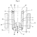
Fig. 2 zeigt ein zweites Ausführungsbeispiel einer erfindungsgemäßen Vorrichtung zum Verdampfen einer Metallschmelze. -
Fig. 3 zeigt ein perspektivisches Schnittbild der Vorrichtung gemäß dem zweiten Ausführungsbeispiel ausFig. 2 . -
Fig. 4 zeigt eine dritte Vorrichtung zum Verdampfen einer Metallschmelze. -
Fig. 5 zeigt ein viertes Ausführungsbeispiel einer erfindungsgemäßen Vorrichtung zum Verdampfen einer Metallschmelze.
-
Fig. 1 shows a first apparatus for evaporating a molten metal. -
Fig. 2 shows a second embodiment of a device according to the invention for evaporating a molten metal. -
Fig. 3 shows a perspective sectional view of the device according to the second embodimentFig. 2 , -
Fig. 4 shows a third apparatus for evaporating a molten metal. -
Fig. 5 shows a fourth embodiment of a device according to the invention for evaporating a molten metal.
In
Die Heizwirkung wird in diesem nicht einschränkenden Beispiel durch eine elektromagnetische Strahlung 115 bewirkt, wobei die Quelle 110 beispielsweise eine die Strahlung erzeugende Hochfrequenzspule aufweisen kann. Die Strahlung bzw. ihre Wellenlänge oder ihr Wellenlängenspektrum ist auf das Material der Metallschmelze 105 abgestimmt, so dass sich dieses über elektromagnetische Induktion aufheizt. Die Metallschmelze 105 dient hier entsprechend als Suszeptormaterial. Die Induktionsleistung kann durch eine Steuerung der Quelle 110 eingestellt werden. Die maximale Leistung reicht aus, das Metallmaterial zu schmelzen.The heating effect is effected in this non-limiting example by
Der Tiegel kann beispielsweise aus einem nicht leitendem, thermisch und chemisch beständigen, wie z.B. pyrolytisch abgeschiedenes Bornitrid (pBN) oder anderen geeigneten Materialien gebildet sein, und ist hier durch einen Deckel 119 abgeschlossen, um ein Entweichen des verdampfenden Metallgases zu verhindern.For example, the crucible may be made of a nonconductive, thermally and chemically resistant, such as pyrolytically deposited boron nitride (pBN) or other suitable materials be formed, and is hereby closed by a
Der erste Tiegel 103 und der zweite Tiegel 102 sind über eine Wärmekopplung 112 thermisch miteinander gekoppelt. Es kann sich dabei um ein Material mit hoher Wärmeleitfähigkeit handeln, so dass eine Schmelze 106, die im ersten Tiegel 103 vorgesehen ist und beispielsweise auch das gleiche oder eines ähnlichen Material wie in der Schmelze 105 umfasst, insbesondere auch niedrig schmelzende Metalle wie z.B. Gallium, Indium, Aluminium oder Mischungen derselben etc., auf nahezu die gleiche Temperatur gebracht wird, wie die Metallschmelze 105 in dem zweiten Tiegel 102.The
Andererseits findet kein oder nur ein unwesentlicher, vernachlässigbarer direkter Wärmeeintrag durch die Quelle 110 in das im ersten Tiegel 103 enthaltene Material 106 statt. Dies liegt daran, dass die Metallschmelze 105 im zweiten Tiegel 102 das Material oder die Metallschmelze 106 im ersten Tiegel von der elektromagnetischen Strahlung 115 abschirmt, welche den Wärmeeintrag über Induktion 116 bewirkt. Die Eindringtiefe in der Metallschmelze 116 ist dabei vergleichsweise gering, die Induktion bleibt im Wesentlichen oberflächlich.On the other hand, no or only an insignificant, negligible direct heat input through the
Die Abschirmung tritt deshalb ein, weil der zweite Tiegel 102 von der Heizungsquelle 110 aus betrachtet räumlich vor dem ersten Tiegel 103 angeordnet ist und die die Induktion 116 bewirkende elektromagnetische Strahlung 115 von der Metallschmelze 105 im zweiten Tiegel 102 absorbiert wird.The shielding occurs because, viewed from the
Infolge der indirekten Erwärmung über die Wärmeleitung aus dem zweiten Tiegel vermittels der Wärmekopplung 112 wird der flüssige Zustand der Metallschmelze aufrecht erhalten, wobei das Metall aus der Schmelze verdampft, welches in
Optional können die beiden Tiegel 103 und 102 auch durch eine Leitung 114 verbunden sein, die einem Austausch zwischen den beiden Schmelzen oder einem Nachfließen zum Ersatz verdampfter Schmelze im ersten Tiegel dienen kann. Am zweiten Tiegel kann dazu auch eine Nachfüllvorrichtung für das Material der Schmelze vorgesehen sein (nicht dargestellt).Optionally, the two
Der Metalldampf bzw. das Metallgas 109 wird gemäß diesem Ausführungsbeispiel entweder aufgefangen und in einer Transportleitung 111 von einem Trägergas 108 mitgeführt, um im weiteren einer gewünschten Verwendung zugeführt zu werden oder im Vakuum als Partikelstrahl (ohne Transportleitung 111) abtransportiert.The metal vapor or the
Die Vorrichtung befindet sich in einem Quarzglasreaktor 16, der mit einem Vakuumsystem (nicht gezeigt) verbunden ist, mit welchem ein definierter Arbeitsdruck zwischen 1 und 1000 mbar eingestellt werden kann. Die Erfindung ist aber keines falls auf solche Druckbereiche begrenzt und höhere Drücke sind ebenso möglich.The device is located in a
Die Vorrichtung umfasst ein konzentrisch angeordnetes, zylindrisches DoppelkammerTiegelsystem in vertikaler Aufstellung mit einem ersten Tiegelbereich 26 und einem zweiten Tiegelbereich 25. Der zweite Tiegelbereich 25 umschließt den ersten Tiegelbereich 26 zylindermantelförmig und schirmt ihn nach außen ab. Der erste Tiegelbereich 26 umschließt einen Kanal 28, der sich entlang der in diesem speziellen Beispiel vertikalen Symmetrieachse der Vorrichtung erstreckt. Der erste Tiegelbereich 26 ist mit dem Kanal 28 über eine Öffnung verbunden, um das verdampfte Material abgeben zu können. Im Beispiel besteht die Öffnung in einem ringförmigen Gebiet des nach oben hin offenen ersten Tiegelbereichs 26. Die Öffnungen können selbstverständlich auch seitlich gerichtet sein. Außerdem kann der Durchmesser der Öffnungen von außen steuerbar eingerichtet sein.The device comprises a concentrically arranged, cylindrical, double-chamber crucible system in a vertical position with a
Der erste, innere Tiegelbereich 26 wird in diesem Ausführungsbeispiel durch die Wand eines nach unten geöffneten, trichterförmigen Elements 4 und durch die innere Wand 3 des zweiten, äußeren Tiegelbereiches 25 gebildet. Der Tiegel kann wiederum aus einem nicht leitendem, thermisch und chemisch beständigen, wie z.B. pBN oder anderen geeigneten Materialien bestehen.The first,
Der erste Tiegelbereich 26 enthält die zu verdampfende Metallschmelze 6. Durch eine geeignete Nachfülleinrichtung, z.B. eine Kapillare (nicht in
Der zweite Tiegelbereich 25 wird durch das Tiegelelement 3 (Innenwand), durch den sich aufweitenden Teil des umgedrehten trichterförmigen Elements 4 (Boden) und durch einen äußeren Tiegel 2 (Außenwand) gebildet. Die den ersten und zweiten Tiegelbereichen 25, 26 gemeinsame Wand 3 kann Öffnungen enthalten (nicht dargestellt), um einen Materialaustausch zwischen den beiden Tiegelbereichen zu ermöglichen. Die Öffnungen können insbesondere im unteren Bereich der Tiegel oder Tiegelbereiche nach Art eines Siphons ausgebildet sein , wobei dann die Schmelzoberflächen in den beiden Tiegeln gleich hoch sind..The
Im zweiten Tiegelbereich 25 ist eine gleiche oder eine ähnliche Metallschmelze (Suszeptor 5, beispielsweise ein ähnlich niedrig schmelzendes Metall) wie im inneren Tiegelbereich 26 eingebracht. Der zweite Tiegelbereich 25 ist im oberen Bereich durch einen Deckel 27 verschlossen, um das Verdampfen des Materials zu verhindern. Für Nachfüll- oder Messzwecke befindet sich im Deckel die Bohrung 34, die ansonsten mit der Schraube 35 verschlossen ist.In the
Im Bereich des Doppelkammer-Tiegelsystems 25, 26 ist außerhalb des Quarzglas-Reaktors 16 eine Heizungsquelle 10 in Form einer Hochfrequenzspule angeordnet. Die Spule (Heizungsquelle 10) erzeugt eine auf die Metallschmelze des äußeren Tiegelbereiches 25 abgestimmte Strahlung, so dass diese durch Induktion erhitzt werden kann. Die Metallschmelze im äußeren Tiegelbereich 26 wirkt damit als Suszeptor 5 für die elektro-magnetische Strahlung.In the region of the double-
Die Dicke des Suszeptors, d.h. der innere Abstand zwischen den Tiegelelementen 2 und 3 des äußeren Tiegelbereiches ist größer als die Eindringtiefe der elektromagnetischen Strahlung der Hochfrequenzspule (Heizungsquelle 10). Damit wird gewährleistet, dass die Metallschmelze 6 im inneren Tiegelbereich 26 nicht oder nicht wesentlich durch die Strahlung der Spule beeinflusst wird.The thickness of the susceptor, ie the inner distance between the
Die Schmelze 6 im inneren Tiegelbereich 26 wird vielmehr durch Wärmeleitung aus dem zweiten Tiegelbereich 25 über die Wand des Tiegelelements 3 geheizt. Durch die konzentrische Anordnung der Tiegelbereiche ist die Grenzfläche zwischen den Tiegelbereichen 25, 26 im Verhältnis zum Volumeninhalt besonders groß, was eine effiziente Wärmeübertragung begünstigt.Rather, the
Für die Angleichung der Temperaturen in den Metallschmelzen 5 und 6 muss das Tiegelmaterial des Tiegelelementes 3 die Wärmeübertragung ermöglichen, was z.B. bei der Verwendung von pBN gegeben ist. Die Erfindung ist aber nicht auf diese Materialauswahl beschränkt.For the adjustment of the temperatures in the metal melts 5 and 6, the crucible material of the
Die Temperatur in der Metallschmelze (Suszeptormaterial 5) und/oder in der Metallschmelze 6 kann mit Hilfe von Thermoelementen (in
Ein Vorteil entsteht bei diesem Aufbau dadurch, dass negative Auswirkungen der mit der Induktionsheizung verbundenen elektromagnetischen Felder, wie das Spritzen bzw. die Tröpfchenbildung an der Oberfläche einer Schmelze, auf den äußeren, abgeschlossenen Tiegelbereich 25 beschränkt bleiben. Die Metallschmelze im inneren Tiegelbereich 26 kann dagegen ohne Tröpfchenbildung stabil und homogen verdampfen, was eine wesentliche Voraussetzung für eine verbesserte Qualität der nachfolgenden Prozesse darstellt.An advantage of this construction is that negative effects of the electromagnetic fields associated with the induction heating, such as spraying or droplet formation on the surface of a melt, are limited to the outer, closed
Ein weiterer Vorteil bei diesem Aufbau entsteht dadurch, dass der Suszeptor 5 als wesentliche Kontaminationsquelle im System entfällt, was ebenfalls eine wesentliche Voraussetzung für eine verbesserte Qualität der nachfolgenden Prozesse darstellt.Another advantage of this structure arises from the fact that the
Der vom Tiegelelement 4 des inneren Tiegels begrenzte zentrale Kanal 28 wird vom Trägergas 8 durchströmt. Das Trägergas 8 dient der Einstellung des Gesamtdruckes im Reaktor 16 sowie dem Transport und der Verdünnung der aus dem Schmelzvorrat 33 des inneren Tiegelbereiches 26 verdampften Metallspezies in der Gasphase.The limited by the crucible 4 of the inner crucible
Das Trägergas 8 kann aus einem beliebigen Inertgas, z.B. Argon, Wasserstoff, Stickstoff oder geeigneten Mischungen von Inertgasen gebildet sein. Je nach Strömungsrichtung des Trägergases 8 axial nach oben oder nach unten werden die verdampften Metallspezies nach oben oder nach unten aus dem Bereich des Tiegelsystems heraus transportiert. Die möglichen Strömungsrichtungen des Trägergases 8 sind in
Neben dem Gesamtdruck im Reaktor stellt der Trägergasfluss 8 einen weiteren wesentlichen Parameter für die flexible Einstellung der Transportrate und -richtung der verdampften Metallspezies im System dar.In addition to the total pressure in the reactor, the
Die Trichterform des den Kanal 28 begrenzenden Tiegelelementes 4 ermöglicht zusammen mit einer geeignet gewählten, konstanten Strömungsgeschwindigkeit eine im Wesentlichen wirbelfreie Trägergasströmung und damit einen stationären Transport der verdampften Metallspezies mit konstanter Transportrate, was wiederum eine wesentliche Voraussetzung für eine verbesserte Qualität der nachfolgenden Prozesse darstellt.The funnel shape of the crucible element 4 delimiting the
Die Vorrichtung gemäß dem zweiten Ausführungsbeispiel ist jedoch nicht auf die in
Die Vorrichtung gemäß dem zweiten Ausführungsbeispiel ist ferner nicht auf die Verwendung eines Trägergases beschränkt. Die Verdampfung der Metallschmelze im Hochvakuum ist ebenfalls möglich. Dann ist jedoch der zentrale Kanal 28 ohne Funktion, weshalb in diesem Fall die Verwendung der Vorrichtung in der unten beschriebenen dritten Ausführungsform (vgl.
Für den Betrieb der Vorrichtung gemäß
Die Vorrichtung befindet sich in einer Vakuumkammer aus Edelstahl oder einem anderen vakuumfesten Material (nicht gezeigt), die mit einem Vakuumsystem (nicht gezeigt) verbunden ist, mit welchem ein Druck von weniger als 10-4 mbar eingestellt werden kann.The device is housed in a vacuum chamber of stainless steel or other vacuum-resistant material (not shown) connected to a vacuum system (not shown) with which a pressure of less than 10 -4 mbar can be set.
Die Vorrichtung umfasst ein konzentrisch angeordnetes, zylindrisches Doppelkammer-Tiegelsystem in vertikaler Aufstellung, welches analog zum zweiten Ausführungsbeispiel (
Der äußere Tiegelbereich 26 wird in diesem Ausführungsbeispiel durch einen zylindrischen Tiegel mit geschlossenem Boden 2, durch ein beiderseits offenes, zylindrisches Tiegelelement 3 mit kleinerem Durchmesser als der Tiegel 2 und durch ein kreisförmiges Deckelelement 27 gebildet. Für Nachfüll- und Messzwecke enthält das Deckelelement eine Bohrung 34, die mit einer Schraube 35 verschlossen werden kann.The
Der innere Tiegelbereich 25 wird durch das innere Tiegelelement 3 und den Boden des Tiegelelementes 2 seitlich und nach unten hin begrenzt. Der Aufbau der Heizung, d.h. der Spule als Heizungsquelle 10 (in
Die Heizung des Tiegelsystems bis hin zur Einstellung eines definierten Partialdrucks der aus der Metallschmelze 6 verdampften Spezies entspricht den im zweiten Ausführungsbeispiel (
Im Unterschied zum zweiten Ausführungsbeispiel (
Die Vorrichtung befindet sich in einem Quarzglasreaktor (nicht gezeigt), der mit einem Vakuumsystem (nicht gezeigt) verbunden ist, mit welchem genau wie im zweiten Ausführungsbeispiel (
Die Vorrichtung umfasst ein horizontal angeordnetes Doppelkammer-Tiegelsystem, welches einen oberen Tiegelbereich und einen unteren Tiegelbereich umfasst.The apparatus comprises a horizontally arranged dual-chamber crucible system comprising an upper crucible region and a lower crucible region.
Der obere Tiegelbereich wird in diesem Ausführungsbeispiel durch einen Behälter 2a mit einem rechteckigen Querschnitt und einem passenden Deckel 27 gebildet. Der untere Tiegelbereich wird durch einen weiteren Behälter 2 mit rechteckigem Querschnitt und einen passenden Deckel 3 gebildet. Die Deckelelemente 3, 27 enthalten Öffnungen 34 für Nachfüllzwecke, die mit Schrauben 35 verschlossen werden können. Im Fall des Deckelelementes 27 des oberen Behälters 2a kann die Öffnung 34 auch für die Temperaturmessung während des Prozesses benutzt werden.The upper crucible region is formed in this embodiment by a
Im Boden des oberen Tiegelbehälters 2a ist eine ausgedehnte Vertiefung ausgebildet, die einen Großteil der gesamten Bodenfläche umfasst. Im Deckelelement 3 des unteren Tiegelbehälters 2 ist eine zur Vertiefung des oberen Behälterbodens konforme Vertiefung ausgebildet.In the bottom of the
Die Tiegelbehälter 2, 2a dienen der Aufnahme des Suszeptormaterials 5. Das zu verdampfende Metall (Metallschmelze 6) ist in der Vertiefung des Deckelelementes 3 des unteren Tiegelbehälters 2 eingebracht.The
An den gegenüberliegenden Stirnflächen des oberen Tiegelbehälters 2a sind flache, rechteckige Aussparungen vorhanden, so dass sich bei der Anordnung der Tiegelelemente gemäß
Der Kanal 28, der sich zwischen den gegenüberliegenden Stirnflächen des Tiegelsystems erstreckt, wird vom Trägergas 8 durchströmt. Durch den flachen Kanalquerschnitt wird eine große Kontaktfläche zwischen dem Trägergas und der zu verdampfenden Metallschmelze 6 bei gleichzeitig weitgehend laminarer Strömung des Trägergases 8 erreicht, wodurch ein effektiver und stationärer Transport der verdampften Metallspezies gewährleistet wird.The
Im Übrigen gelten die für das zweite Ausführungsbeispiel (
Die Vorrichtung gemäß dem vierten Ausführungsbeispiel ist jedoch nicht auf die in
Die Vorrichtung gemäß dem vierten Ausführungsbeispiel ist ferner nicht auf die Verwendung eines Trägergases beschränkt. Die Verdampfung der Metallschmelze im Hochvakuum ist ebenfalls möglich.The device according to the fourth embodiment is further not limited to the use of a carrier gas. The evaporation of the molten metal in a high vacuum is also possible.
Die Heizung des Tiegelsystems bis hin zur Einstellung eines definierten Partialdrucks der aus der Metallschmelze 6 verdampften Spezies entspricht den im zweiten Ausführungsbeispiel (
Claims (13)
- Device for evaporating a metal melt (6), comprising:a first crucible or crucible portion (2, 2a; 26) configured to receive the metal melt (6, 106), comprising at least one aperture, through which the evaporated metal may pass off;a second crucible or crucible portion (25, 102) configured to receive a susceptor material (5, 105);a heating source (10), which is arranged such that it heats the susceptor material (5, 105) in the second crucible or crucible portion (25, 102) by means of incident electromagnetic induction, wherein it does not or only negligibly heat the metal melt (6, 106) in the first crucible or crucible portion (2, 2a; 26);wherein the first crucible or crucible portion (2, 2a; 26) and the second crucible or crucible portion (25, 102) are thermally coupled, such that the metal melt (6, 106) can attain a desired temperature;wherein the first crucible or crucible portion (2, 2a; 26) comprises an inner channel (28) towards which the at least one aperture extends; wherein there is further provided an arrangement for forming a flow of a carrier gas (8) directed through the channel (28) in order to carry the evaporated metal passed off from the at least one aperture.
- Device according to claim 1, wherein the first crucible or crucible portion (2, 2a; 26) and the second crucible or crucible portion (25) include a common crucible wall (3).
- Device according to claim 1 or 2, wherein
the susceptor material (5, 105) also is a metal melt; and/or
the metal melt (6, 106) and the susceptor material (5, 105) include the same or a similar material, in particular one or correspondingly two out of gallium, indium or aluminium, or mixtures of the same. - Device according to claim 3, wherein the content of each of the first crucible or crucible portion (2, 2a; 26) and the second crucible or crucible portion (25, 102) are in communication with each other via a conduit (114) or an opening in a common separation wall (17).
- Device according to claim 4, wherein the connection between the first crucible or crucible portion (2, 2a; 26) and the second crucible or crucible portion (25, 102) is formed in the manner of a siphon.
- Device according to one of claims 1 through 5, wherein the first crucible or crucible portion (26) is formed substantially cylindrical or at least as one or more corresponding segments, and wherein the second crucible or crucible portion (25) encloses the first crucible or crucible portion (25) at least like a cylinder shell.
- Device according to one of claims 1 through 6, comprising a thermal element, which is provided in the first crucible or crucible portion (2, 2a; 26) for detecting the temperature; and/or a replenishment element, which is configured to replenish the material of the metal melt in a first crucible or crucible portion (2, 2a; 26) or in the case of claim 4 in the first or second crucible or crucible portion (25, 102).
- Device according to one of claims 1 through 7, wherein the first crucible or crucible portion (2, 2a; 26) and/or the second crucible or crucible portion (25, 102) is formed from a dielectric material, in particular pyrolytic boron nitride.
- Device according to claim 6, or one of claims 7 through 8 when depending on claim 6, wherein the cylinder symmetric first crucible or crucible portion (26) comprises the inner channel (28) along its longitudinal axis, towards which the at least one opening extends.
- Device according to claim 9, wherein the inner channel (28) opens at its one end in the flow direction in the form of a funnel.
- Method of evaporating a material from a metal melt (6, 106), comprising:providing a susceptor material (5) in the second crucible or crucible portion (25, 102);supplying heat by means of inductive heating of the susceptor material (5, 105);providing the metal melt (6, 106) in a first crucible or crucible portion (2, 2a; 26, 103) being thermally coupled with the second crucible or crucible portion (25, 102), wherein the first crucible or crucible portion (2, 2a; 26) encloses an inner channel (28);transferring the heat from the susceptor material (5, 105) in the second crucible or crucible portion onto the metal melt (6, 106) in the first crucible or crucible portion (2, 2a; 26, 103) via thermal coupling, such that the metal melt (6, 106) reaches a desired temperature;evaporating the metal melt (6, 106) in the first crucible or crucible portion (2, 2a; 26, 103) at the desired temperature including the dispense of the evaporated material from the metal melt (6) in the first crucible or crucible portion (26) via one or more apertures into the inner channel (28);supplying a flow of a carrier gas (8) into the inner channel (28) for carrying the evaporated material.
- Method according to claim 11, wherein, in the steps of providing the susceptor material and the metal melt, the metal melt (6, 106) and the susceptor material (5, 105) comprise the same material.
- Method according to claim 12, wherein the metal melt (6, 106) and the susceptor material (5, 105) are brought into connection with each other via an opening or a conduit (114) between the crucibles or crucible portions, such that the heat transfer is effected also by convection, diffusion and/or direct heat transfer.
Priority Applications (1)
| Application Number | Priority Date | Filing Date | Title |
|---|---|---|---|
| PL12791755T PL2622112T3 (en) | 2011-12-21 | 2012-11-27 | Apparatus and process for evaporation of material from a metal melt |
Applications Claiming Priority (2)
| Application Number | Priority Date | Filing Date | Title |
|---|---|---|---|
| DE102011089501A DE102011089501B4 (en) | 2011-12-21 | 2011-12-21 | Apparatus and method for vaporizing material from a molten metal |
| PCT/EP2012/073677 WO2013092124A1 (en) | 2011-12-21 | 2012-11-27 | Apparatus and process for evaporation of material from a metal melt |
Publications (2)
| Publication Number | Publication Date |
|---|---|
| EP2622112A1 EP2622112A1 (en) | 2013-08-07 |
| EP2622112B1 true EP2622112B1 (en) | 2015-01-07 |
Family
ID=47257799
Family Applications (1)
| Application Number | Title | Priority Date | Filing Date |
|---|---|---|---|
| EP12791755.7A Active EP2622112B1 (en) | 2011-12-21 | 2012-11-27 | Apparatus and process for evaporation of material from a metal melt |
Country Status (5)
| Country | Link |
|---|---|
| US (1) | US10767255B2 (en) |
| EP (1) | EP2622112B1 (en) |
| DE (1) | DE102011089501B4 (en) |
| PL (1) | PL2622112T3 (en) |
| WO (1) | WO2013092124A1 (en) |
Cited By (1)
| Publication number | Priority date | Publication date | Assignee | Title |
|---|---|---|---|---|
| DE102021200421A1 (en) | 2021-01-18 | 2022-07-21 | Alethia-Group Gmbh | Spray unit and method for spraying a solid-derived material |
Families Citing this family (6)
| Publication number | Priority date | Publication date | Assignee | Title |
|---|---|---|---|---|
| DE102013108997A1 (en) * | 2013-08-20 | 2015-02-26 | Von Ardenne Gmbh | Crucible arrangement and vacuum coating system |
| DE102013224319A1 (en) * | 2013-11-27 | 2015-06-11 | Eos Gmbh Electro Optical Systems | Method and device for the generative production of at least one component region of a component |
| CN104726828B (en) * | 2015-03-26 | 2017-06-06 | 青州市宝丰镀膜科技有限公司 | Double-open type sensing heating coating machine |
| CN111278770B (en) | 2017-10-27 | 2023-04-21 | 凯文艾伦杜利股份有限公司 | System and method for producing high purity silicon |
| JP7018816B2 (en) * | 2018-04-26 | 2022-02-14 | 昭和電工株式会社 | Crucible and SiC single crystal growth device |
| GB2586634B (en) * | 2019-08-30 | 2022-04-20 | Dyson Technology Ltd | Multizone crucible apparatus |
Family Cites Families (25)
| Publication number | Priority date | Publication date | Assignee | Title |
|---|---|---|---|---|
| NL6917398A (en) * | 1969-03-18 | 1970-09-22 | ||
| CH564393A5 (en) * | 1973-11-05 | 1975-07-31 | Bbc Brown Boveri & Cie | |
| CH613129A5 (en) * | 1975-06-11 | 1979-09-14 | Prolizenz Ag | |
| US3980438A (en) * | 1975-08-28 | 1976-09-14 | Arthur D. Little, Inc. | Apparatus for forming semiconductor crystals of essentially uniform diameter |
| US4036595A (en) * | 1975-11-06 | 1977-07-19 | Siltec Corporation | Continuous crystal growing furnace |
| US4125086A (en) * | 1977-01-06 | 1978-11-14 | The United States Of America As Represented By The Secretary Of The Army | Nozzle beam type metal vapor source |
| US4352784A (en) * | 1979-05-25 | 1982-10-05 | Western Electric Company, Inc. | Double crucible Czochralski crystal growth apparatus |
| US4246064A (en) * | 1979-07-02 | 1981-01-20 | Western Electric Company, Inc. | Double crucible crystal growing process |
| JPS58197270A (en) * | 1982-05-12 | 1983-11-16 | Mitsubishi Electric Corp | Crucible for evaporating source |
| US4791261A (en) | 1987-09-23 | 1988-12-13 | International Business Machines Corporation | Crucible for evaporation of metallic film |
| JPH10158088A (en) * | 1996-11-25 | 1998-06-16 | Ebara Corp | Production of solid material and device therefor |
| US6649888B2 (en) * | 1999-09-23 | 2003-11-18 | Codaco, Inc. | Radio frequency (RF) heating system |
| US6279352B1 (en) * | 1999-12-30 | 2001-08-28 | Corning Incorporated | Long hot zone furnace element and optical fiber drawing method practiced therewith |
| US6550279B1 (en) * | 2000-09-01 | 2003-04-22 | Corning Incorporated | Process for drawing optical fiber from a multiple crucible apparatus with a thermal gradient |
| JP3864696B2 (en) * | 2000-11-10 | 2007-01-10 | 株式会社デンソー | Method and apparatus for producing silicon carbide single crystal |
| JP2003074828A (en) * | 2001-08-29 | 2003-03-12 | Hikari Tekku Kk | Melting device for ash |
| US6588235B2 (en) * | 2001-08-30 | 2003-07-08 | Corning Incorporated | Method of centering a fiber core in a multiple-crucible method |
| US7361220B2 (en) * | 2003-03-26 | 2008-04-22 | Matsushita Electric Industrial Co., Ltd. | Method of manufacturing group III nitride single crystal, device used for the method and group III nitride single crystal obtained by the method |
| JP2005336558A (en) * | 2004-05-27 | 2005-12-08 | Konica Minolta Medical & Graphic Inc | Vapor deposition system and vapor deposition method |
| US7691199B2 (en) * | 2004-06-18 | 2010-04-06 | Memc Electronic Materials, Inc. | Melter assembly and method for charging a crystal forming apparatus with molten source material |
| US7161126B2 (en) * | 2004-11-10 | 2007-01-09 | Bwxt Y-12, Llc | Microwave heat treating of manufactured components |
| US8361227B2 (en) * | 2006-09-26 | 2013-01-29 | Ii-Vi Incorporated | Silicon carbide single crystals with low boron content |
| EP1967604A1 (en) * | 2007-03-08 | 2008-09-10 | Applied Materials, Inc. | Evaporation crucible and evaporation apparatus with directional evaporation |
| US7862656B2 (en) * | 2007-07-03 | 2011-01-04 | Siemens Medical Solutions Usa, Inc. | Apparatus and method for growing a crystal and heating an annular channel circumscribing the crystal |
| US8784559B2 (en) * | 2010-09-09 | 2014-07-22 | Siemens Medical Solutions Usa, Inc. | Method and apparatus for continuous crystal growth |
-
2011
- 2011-12-21 DE DE102011089501A patent/DE102011089501B4/en active Active
-
2012
- 2012-11-27 PL PL12791755T patent/PL2622112T3/en unknown
- 2012-11-27 EP EP12791755.7A patent/EP2622112B1/en active Active
- 2012-11-27 WO PCT/EP2012/073677 patent/WO2013092124A1/en active Application Filing
- 2012-12-20 US US13/721,086 patent/US10767255B2/en active Active
Cited By (1)
| Publication number | Priority date | Publication date | Assignee | Title |
|---|---|---|---|---|
| DE102021200421A1 (en) | 2021-01-18 | 2022-07-21 | Alethia-Group Gmbh | Spray unit and method for spraying a solid-derived material |
Also Published As
| Publication number | Publication date |
|---|---|
| DE102011089501A1 (en) | 2013-06-27 |
| US20130163967A1 (en) | 2013-06-27 |
| PL2622112T3 (en) | 2015-06-30 |
| WO2013092124A1 (en) | 2013-06-27 |
| EP2622112A1 (en) | 2013-08-07 |
| DE102011089501B4 (en) | 2013-10-10 |
| US10767255B2 (en) | 2020-09-08 |
Similar Documents
| Publication | Publication Date | Title |
|---|---|---|
| EP2622112B1 (en) | Apparatus and process for evaporation of material from a metal melt | |
| WO2006040359A1 (en) | Method for producing gan or algan crystals | |
| WO2012175334A2 (en) | Method and device for depositing oleds, in particular evaporation device therefor | |
| DE112017002153T5 (en) | EFFUSION CELLS, SEPARATION SYSTEMS WITH EFFUSION CELLS AND ASSOCIATED METHODS | |
| DE4310744A1 (en) | Device for producing SiC single crystals | |
| EP0213556A2 (en) | Apparatus for the continuous evaporation of inorganic compounds using a photon-producing thermal-radiation source | |
| WO2003048406A2 (en) | Coating method and coating | |
| EP3610050B1 (en) | Coating apparatus and method for reactive vapor phase deposition on a substrate under vacuum | |
| DE10224908A1 (en) | Device for coating a flat substrate used in the production of flat TV screens with organic illuminating diodes comprises a fixed vaporizer source for vaporizing materials | |
| EP3523466B1 (en) | Device and method for applying a carbon layer | |
| DE102007020852A1 (en) | Gas supply system and method for providing a gaseous deposition medium | |
| EP3209809B1 (en) | Temperature-controlled gas supply line with dilution gas flows supplied at multiple locations | |
| EP1422313A1 (en) | Apparatus and method for vacuum vapor deposition of a coating material with continuated material replenishment | |
| DE102005049906B4 (en) | Method and apparatus for evaporating evaporation material | |
| WO2013097842A2 (en) | Device for evaporating a substance for evaporation | |
| WO2021115904A1 (en) | Method and device for producing a single crystal of silicon, which single crystal is doped with n-type dopant | |
| DE69634071T2 (en) | Method and device for coating a substrate | |
| DE10319742A1 (en) | Powdered organic semiconductors and methods for vapor deposition on a carrier | |
| DE1621295C3 (en) | Method and device for covering substrates by vapor deposition | |
| DE102012022744B4 (en) | Device for adjusting a gas phase in a reaction chamber | |
| DE1521174B2 (en) | METHOD FOR THERMAL EVAPORATION OF A MIXTURE OF SUBSTANCES IN A VACUUM | |
| DE102011016814B4 (en) | Evaporator cell closure device for a coating system | |
| DE102004046279B4 (en) | Steam source and coating part of a plant for producing thin layers under vacuum conditions of at least two different coating components with respect to their vapor pressure | |
| DE102009004502A1 (en) | Evaporating an evaporation material in the form of organic material, comprises heating the evaporation material in a process chamber of an evaporating device, evaporating over an evaporating surface and then depositing on a substrate | |
| WO2013038023A1 (en) | Vapor source for depositing thin films |
Legal Events
| Date | Code | Title | Description |
|---|---|---|---|
| PUAI | Public reference made under article 153(3) epc to a published international application that has entered the european phase |
Free format text: ORIGINAL CODE: 0009012 |
|
| 17P | Request for examination filed |
Effective date: 20130409 |
|
| AK | Designated contracting states |
Kind code of ref document: A1 Designated state(s): AL AT BE BG CH CY CZ DE DK EE ES FI FR GB GR HR HU IE IS IT LI LT LU LV MC MK MT NL NO PL PT RO RS SE SI SK SM TR |
|
| GRAP | Despatch of communication of intention to grant a patent |
Free format text: ORIGINAL CODE: EPIDOSNIGR1 |
|
| DAX | Request for extension of the european patent (deleted) | ||
| INTG | Intention to grant announced |
Effective date: 20140620 |
|
| RIN1 | Information on inventor provided before grant (corrected) |
Inventor name: PAETZOLD, OLF Inventor name: LUKIN, GLEB Inventor name: STELTER, MICHAEL |
|
| GRAS | Grant fee paid |
Free format text: ORIGINAL CODE: EPIDOSNIGR3 |
|
| GRAA | (expected) grant |
Free format text: ORIGINAL CODE: 0009210 |
|
| AK | Designated contracting states |
Kind code of ref document: B1 Designated state(s): AL AT BE BG CH CY CZ DE DK EE ES FI FR GB GR HR HU IE IS IT LI LT LU LV MC MK MT NL NO PL PT RO RS SE SI SK SM TR |
|
| REG | Reference to a national code |
Ref country code: GB Ref legal event code: FG4D Free format text: NOT ENGLISH |
|
| REG | Reference to a national code |
Ref country code: CH Ref legal event code: EP |
|
| REG | Reference to a national code |
Ref country code: IE Ref legal event code: FG4D Free format text: LANGUAGE OF EP DOCUMENT: GERMAN |
|
| REG | Reference to a national code |
Ref country code: AT Ref legal event code: REF Ref document number: 705806 Country of ref document: AT Kind code of ref document: T Effective date: 20150215 |
|
| REG | Reference to a national code |
Ref country code: DE Ref legal event code: R096 Ref document number: 502012002063 Country of ref document: DE Effective date: 20150226 |
|
| REG | Reference to a national code |
Ref country code: NL Ref legal event code: VDEP Effective date: 20150107 |
|
| REG | Reference to a national code |
Ref country code: LT Ref legal event code: MG4D |
|
| REG | Reference to a national code |
Ref country code: PL Ref legal event code: T3 |
|
| PG25 | Lapsed in a contracting state [announced via postgrant information from national office to epo] |
Ref country code: BG Free format text: LAPSE BECAUSE OF FAILURE TO SUBMIT A TRANSLATION OF THE DESCRIPTION OR TO PAY THE FEE WITHIN THE PRESCRIBED TIME-LIMIT Effective date: 20150407 Ref country code: NO Free format text: LAPSE BECAUSE OF FAILURE TO SUBMIT A TRANSLATION OF THE DESCRIPTION OR TO PAY THE FEE WITHIN THE PRESCRIBED TIME-LIMIT Effective date: 20150407 Ref country code: ES Free format text: LAPSE BECAUSE OF FAILURE TO SUBMIT A TRANSLATION OF THE DESCRIPTION OR TO PAY THE FEE WITHIN THE PRESCRIBED TIME-LIMIT Effective date: 20150107 Ref country code: LT Free format text: LAPSE BECAUSE OF FAILURE TO SUBMIT A TRANSLATION OF THE DESCRIPTION OR TO PAY THE FEE WITHIN THE PRESCRIBED TIME-LIMIT Effective date: 20150107 Ref country code: FI Free format text: LAPSE BECAUSE OF FAILURE TO SUBMIT A TRANSLATION OF THE DESCRIPTION OR TO PAY THE FEE WITHIN THE PRESCRIBED TIME-LIMIT Effective date: 20150107 Ref country code: SE Free format text: LAPSE BECAUSE OF FAILURE TO SUBMIT A TRANSLATION OF THE DESCRIPTION OR TO PAY THE FEE WITHIN THE PRESCRIBED TIME-LIMIT Effective date: 20150107 Ref country code: HR Free format text: LAPSE BECAUSE OF FAILURE TO SUBMIT A TRANSLATION OF THE DESCRIPTION OR TO PAY THE FEE WITHIN THE PRESCRIBED TIME-LIMIT Effective date: 20150107 |
|
| PG25 | Lapsed in a contracting state [announced via postgrant information from national office to epo] |
Ref country code: RS Free format text: LAPSE BECAUSE OF FAILURE TO SUBMIT A TRANSLATION OF THE DESCRIPTION OR TO PAY THE FEE WITHIN THE PRESCRIBED TIME-LIMIT Effective date: 20150107 Ref country code: LV Free format text: LAPSE BECAUSE OF FAILURE TO SUBMIT A TRANSLATION OF THE DESCRIPTION OR TO PAY THE FEE WITHIN THE PRESCRIBED TIME-LIMIT Effective date: 20150107 Ref country code: IS Free format text: LAPSE BECAUSE OF FAILURE TO SUBMIT A TRANSLATION OF THE DESCRIPTION OR TO PAY THE FEE WITHIN THE PRESCRIBED TIME-LIMIT Effective date: 20150507 Ref country code: NL Free format text: LAPSE BECAUSE OF FAILURE TO SUBMIT A TRANSLATION OF THE DESCRIPTION OR TO PAY THE FEE WITHIN THE PRESCRIBED TIME-LIMIT Effective date: 20150107 Ref country code: GR Free format text: LAPSE BECAUSE OF FAILURE TO SUBMIT A TRANSLATION OF THE DESCRIPTION OR TO PAY THE FEE WITHIN THE PRESCRIBED TIME-LIMIT Effective date: 20150408 |
|
| REG | Reference to a national code |
Ref country code: DE Ref legal event code: R097 Ref document number: 502012002063 Country of ref document: DE |
|
| PG25 | Lapsed in a contracting state [announced via postgrant information from national office to epo] |
Ref country code: CZ Free format text: LAPSE BECAUSE OF FAILURE TO SUBMIT A TRANSLATION OF THE DESCRIPTION OR TO PAY THE FEE WITHIN THE PRESCRIBED TIME-LIMIT Effective date: 20150107 Ref country code: DK Free format text: LAPSE BECAUSE OF FAILURE TO SUBMIT A TRANSLATION OF THE DESCRIPTION OR TO PAY THE FEE WITHIN THE PRESCRIBED TIME-LIMIT Effective date: 20150107 Ref country code: SK Free format text: LAPSE BECAUSE OF FAILURE TO SUBMIT A TRANSLATION OF THE DESCRIPTION OR TO PAY THE FEE WITHIN THE PRESCRIBED TIME-LIMIT Effective date: 20150107 Ref country code: EE Free format text: LAPSE BECAUSE OF FAILURE TO SUBMIT A TRANSLATION OF THE DESCRIPTION OR TO PAY THE FEE WITHIN THE PRESCRIBED TIME-LIMIT Effective date: 20150107 Ref country code: RO Free format text: LAPSE BECAUSE OF FAILURE TO SUBMIT A TRANSLATION OF THE DESCRIPTION OR TO PAY THE FEE WITHIN THE PRESCRIBED TIME-LIMIT Effective date: 20150107 |
|
| PLBE | No opposition filed within time limit |
Free format text: ORIGINAL CODE: 0009261 |
|
| STAA | Information on the status of an ep patent application or granted ep patent |
Free format text: STATUS: NO OPPOSITION FILED WITHIN TIME LIMIT |
|
| REG | Reference to a national code |
Ref country code: FR Ref legal event code: PLFP Year of fee payment: 4 |
|
| 26N | No opposition filed |
Effective date: 20151008 |
|
| PG25 | Lapsed in a contracting state [announced via postgrant information from national office to epo] |
Ref country code: IT Free format text: LAPSE BECAUSE OF FAILURE TO SUBMIT A TRANSLATION OF THE DESCRIPTION OR TO PAY THE FEE WITHIN THE PRESCRIBED TIME-LIMIT Effective date: 20150107 |
|
| PG25 | Lapsed in a contracting state [announced via postgrant information from national office to epo] |
Ref country code: SI Free format text: LAPSE BECAUSE OF FAILURE TO SUBMIT A TRANSLATION OF THE DESCRIPTION OR TO PAY THE FEE WITHIN THE PRESCRIBED TIME-LIMIT Effective date: 20150107 |
|
| PG25 | Lapsed in a contracting state [announced via postgrant information from national office to epo] |
Ref country code: MC Free format text: LAPSE BECAUSE OF FAILURE TO SUBMIT A TRANSLATION OF THE DESCRIPTION OR TO PAY THE FEE WITHIN THE PRESCRIBED TIME-LIMIT Effective date: 20150107 Ref country code: LU Free format text: LAPSE BECAUSE OF FAILURE TO SUBMIT A TRANSLATION OF THE DESCRIPTION OR TO PAY THE FEE WITHIN THE PRESCRIBED TIME-LIMIT Effective date: 20151127 |
|
| REG | Reference to a national code |
Ref country code: CH Ref legal event code: PL |
|
| PG25 | Lapsed in a contracting state [announced via postgrant information from national office to epo] |
Ref country code: CH Free format text: LAPSE BECAUSE OF NON-PAYMENT OF DUE FEES Effective date: 20151130 Ref country code: LI Free format text: LAPSE BECAUSE OF NON-PAYMENT OF DUE FEES Effective date: 20151130 |
|
| REG | Reference to a national code |
Ref country code: IE Ref legal event code: MM4A |
|
| PG25 | Lapsed in a contracting state [announced via postgrant information from national office to epo] |
Ref country code: IE Free format text: LAPSE BECAUSE OF NON-PAYMENT OF DUE FEES Effective date: 20151127 |
|
| REG | Reference to a national code |
Ref country code: FR Ref legal event code: PLFP Year of fee payment: 5 |
|
| PG25 | Lapsed in a contracting state [announced via postgrant information from national office to epo] |
Ref country code: SM Free format text: LAPSE BECAUSE OF FAILURE TO SUBMIT A TRANSLATION OF THE DESCRIPTION OR TO PAY THE FEE WITHIN THE PRESCRIBED TIME-LIMIT Effective date: 20150107 Ref country code: HU Free format text: LAPSE BECAUSE OF FAILURE TO SUBMIT A TRANSLATION OF THE DESCRIPTION OR TO PAY THE FEE WITHIN THE PRESCRIBED TIME-LIMIT; INVALID AB INITIO Effective date: 20121127 |
|
| PG25 | Lapsed in a contracting state [announced via postgrant information from national office to epo] |
Ref country code: CY Free format text: LAPSE BECAUSE OF FAILURE TO SUBMIT A TRANSLATION OF THE DESCRIPTION OR TO PAY THE FEE WITHIN THE PRESCRIBED TIME-LIMIT Effective date: 20150107 |
|
| PG25 | Lapsed in a contracting state [announced via postgrant information from national office to epo] |
Ref country code: BE Free format text: LAPSE BECAUSE OF NON-PAYMENT OF DUE FEES Effective date: 20151130 |
|
| PG25 | Lapsed in a contracting state [announced via postgrant information from national office to epo] |
Ref country code: MT Free format text: LAPSE BECAUSE OF FAILURE TO SUBMIT A TRANSLATION OF THE DESCRIPTION OR TO PAY THE FEE WITHIN THE PRESCRIBED TIME-LIMIT Effective date: 20150107 |
|
| REG | Reference to a national code |
Ref country code: FR Ref legal event code: PLFP Year of fee payment: 6 |
|
| PG25 | Lapsed in a contracting state [announced via postgrant information from national office to epo] |
Ref country code: TR Free format text: LAPSE BECAUSE OF FAILURE TO SUBMIT A TRANSLATION OF THE DESCRIPTION OR TO PAY THE FEE WITHIN THE PRESCRIBED TIME-LIMIT Effective date: 20150107 Ref country code: MK Free format text: LAPSE BECAUSE OF FAILURE TO SUBMIT A TRANSLATION OF THE DESCRIPTION OR TO PAY THE FEE WITHIN THE PRESCRIBED TIME-LIMIT Effective date: 20150107 Ref country code: PT Free format text: LAPSE BECAUSE OF FAILURE TO SUBMIT A TRANSLATION OF THE DESCRIPTION OR TO PAY THE FEE WITHIN THE PRESCRIBED TIME-LIMIT Effective date: 20150107 |
|
| PG25 | Lapsed in a contracting state [announced via postgrant information from national office to epo] |
Ref country code: AL Free format text: LAPSE BECAUSE OF FAILURE TO SUBMIT A TRANSLATION OF THE DESCRIPTION OR TO PAY THE FEE WITHIN THE PRESCRIBED TIME-LIMIT Effective date: 20150107 |
|
| REG | Reference to a national code |
Ref country code: AT Ref legal event code: MM01 Ref document number: 705806 Country of ref document: AT Kind code of ref document: T Effective date: 20171127 |
|
| PG25 | Lapsed in a contracting state [announced via postgrant information from national office to epo] |
Ref country code: AT Free format text: LAPSE BECAUSE OF NON-PAYMENT OF DUE FEES Effective date: 20171127 |
|
| PGFP | Annual fee paid to national office [announced via postgrant information from national office to epo] |
Ref country code: PL Payment date: 20221116 Year of fee payment: 11 |
|
| PGFP | Annual fee paid to national office [announced via postgrant information from national office to epo] |
Ref country code: GB Payment date: 20231123 Year of fee payment: 12 |
|
| PGFP | Annual fee paid to national office [announced via postgrant information from national office to epo] |
Ref country code: FR Payment date: 20231122 Year of fee payment: 12 Ref country code: DE Payment date: 20231128 Year of fee payment: 12 |
|
| PGFP | Annual fee paid to national office [announced via postgrant information from national office to epo] |
Ref country code: PL Payment date: 20231115 Year of fee payment: 12 |