EP2621827B1 - Food dispenser - Google Patents
Food dispenser Download PDFInfo
- Publication number
- EP2621827B1 EP2621827B1 EP11757597.7A EP11757597A EP2621827B1 EP 2621827 B1 EP2621827 B1 EP 2621827B1 EP 11757597 A EP11757597 A EP 11757597A EP 2621827 B1 EP2621827 B1 EP 2621827B1
- Authority
- EP
- European Patent Office
- Prior art keywords
- cap
- collar
- spout
- spout member
- dispenser according
- Prior art date
- Legal status (The legal status is an assumption and is not a legal conclusion. Google has not performed a legal analysis and makes no representation as to the accuracy of the status listed.)
- Active
Links
Images


Classifications
-
- B—PERFORMING OPERATIONS; TRANSPORTING
- B65—CONVEYING; PACKING; STORING; HANDLING THIN OR FILAMENTARY MATERIAL
- B65D—CONTAINERS FOR STORAGE OR TRANSPORT OF ARTICLES OR MATERIALS, e.g. BAGS, BARRELS, BOTTLES, BOXES, CANS, CARTONS, CRATES, DRUMS, JARS, TANKS, HOPPERS, FORWARDING CONTAINERS; ACCESSORIES, CLOSURES, OR FITTINGS THEREFOR; PACKAGING ELEMENTS; PACKAGES
- B65D47/00—Closures with filling and discharging, or with discharging, devices
- B65D47/04—Closures with discharging devices other than pumps
- B65D47/06—Closures with discharging devices other than pumps with pouring spouts or tubes; with discharge nozzles or passages
- B65D47/08—Closures with discharging devices other than pumps with pouring spouts or tubes; with discharge nozzles or passages having articulated or hinged closures
-
- B—PERFORMING OPERATIONS; TRANSPORTING
- B65—CONVEYING; PACKING; STORING; HANDLING THIN OR FILAMENTARY MATERIAL
- B65D—CONTAINERS FOR STORAGE OR TRANSPORT OF ARTICLES OR MATERIALS, e.g. BAGS, BARRELS, BOTTLES, BOXES, CANS, CARTONS, CRATES, DRUMS, JARS, TANKS, HOPPERS, FORWARDING CONTAINERS; ACCESSORIES, CLOSURES, OR FITTINGS THEREFOR; PACKAGING ELEMENTS; PACKAGES
- B65D47/00—Closures with filling and discharging, or with discharging, devices
- B65D47/04—Closures with discharging devices other than pumps
- B65D47/20—Closures with discharging devices other than pumps comprising hand-operated members for controlling discharge
- B65D47/2018—Closures with discharging devices other than pumps comprising hand-operated members for controlling discharge comprising a valve or like element which is opened or closed by deformation of the container or closure
- B65D47/2031—Closures with discharging devices other than pumps comprising hand-operated members for controlling discharge comprising a valve or like element which is opened or closed by deformation of the container or closure the element being formed by a slit, narrow opening or constrictable spout, the size of the outlet passage being able to be varied by increasing or decreasing the pressure
-
- B—PERFORMING OPERATIONS; TRANSPORTING
- B65—CONVEYING; PACKING; STORING; HANDLING THIN OR FILAMENTARY MATERIAL
- B65D—CONTAINERS FOR STORAGE OR TRANSPORT OF ARTICLES OR MATERIALS, e.g. BAGS, BARRELS, BOTTLES, BOXES, CANS, CARTONS, CRATES, DRUMS, JARS, TANKS, HOPPERS, FORWARDING CONTAINERS; ACCESSORIES, CLOSURES, OR FITTINGS THEREFOR; PACKAGING ELEMENTS; PACKAGES
- B65D51/00—Closures not otherwise provided for
- B65D51/24—Closures not otherwise provided for combined or co-operating with auxiliary devices for non-closing purposes
- B65D51/249—Closures not otherwise provided for combined or co-operating with auxiliary devices for non-closing purposes the closure being specifically formed for supporting the container
Definitions
- the invention is related to the field of food dispensers of the bottom opening type.
- the invention is specifically related to a bottom opening dispenser which comprises a squeeze container holding a viscous food product and a cap stand by means of which the dispenser can be positioned according to an inverted posture, with the discharge spout pointing downwards.
- the container is squeezable, in such a way that the contents can be expelled by exerting a pressure on the container.
- the cap stand of the present dispenser comprises a collar located around the spout, a cap and a hinge that connects said cap to said collar, wherein at least a part of said collar is transparent.
- Dispensers of the bottom opening type are positioned with the discharge opening pointing downwards.
- Such design has several advantages over the other type of dispensers, the so-called top opening dispensers.
- the contents of the bottom opening dispenser are held near the discharge opening under the influence of gravity, which has the advantage that the dispenser can be emptied almost completely.
- the viscosity of a viscous food product such as ketchup, mustard, mayonnaise and the like will not hamper the discharge because the contents are readily available for dispensing.
- the dispenser for liquid detergents has a cover cap, the purpose of which is to dose a predetermined quantity of detergent therein.
- the dispenser may be positioned upside down on said cap.
- the cap is not carried out as a cap stand having a collar and an openable cap or lid, nor has a spout been provided.
- WO-A-2007/130563 is related to a bottom opening dispenser for gel compositions.
- the dispenser has a transparent dispensing cap for supporting the dispenser. There is no cap stand having a collar and a lid or cap which can be opened or closed.
- US 4,723,671 relates to a bottle cap stand for supporting a bottle in an inverted position.
- US 2008/035668 A1 relates to a container for storing, mixing, and dispensing measured volumes of liquid
- US 2003/0121876 A1 relates to a tube container that is resistant to water infiltration into the cavity between the shoulder and the cap.
- the cap stand of dispensers of the bottom opening type provides a stable position of the dispenser on a surface, such as a shelf or table.
- the cap stand usually has considerable cross dimensions which allow the stable position to be obtained.
- the view on the spout is hampered.
- the object of the invention is therefore to provide a food dispenser which allows an improved control of the discharge of the product in question from the container. This object is achieved by means of a food dispenser comprising:
- the stable support of the dispenser in inverted position is still obtained by the cap stand.
- the spout member may be observed by the consumer and thus also the amount of food product which emanates from the spout.
- the cap may be transparent as well.
- the spout member protrudes from the container into the cap stand, whereby good visibility of the spout member is obtained.
- the consumer is now in a position to better control the amount of food product which is discharged from the container through the free opening of the spout member.
- the consumer is able to squeeze the container in a better controlled way so as to obtain the desired amount of food product.
- a food dispenser comprising:
- annular chamber is defined between the spout member and the collar.
- the spout member is thus clearly visible within the annular chamber, whereby the egress of the food product is easily observed.
- a proper chamber is obtained in case the internal diameter of the bottom end of the collar is at least 2 times larger than the external diameter of the bottom end of the spout member.
- the spout member itself is non-transparent.
- the container may be either transparent or non-transparent.
- the collar may be partly transparent; for instance, at least 50% of the collar may be transparent.
- at least 80% of the collar is transparent, more preferably at least 90% of the collar is transparent and most preferably the complete collar is transparent.
- the cap stand including collar, cap and hinge, is transparent
- the spout opening preferably has an internal diameter of less than 1 cm, even more preferably of less than 6 mm, most preferably of less than 4 mm.
- the spout opening has a diameter of at least 0.3 mm, even more preferably of at least 0.5 mm.
- a shield may provided within the annular chamber. This shield extends between the outside of the spout member and the inside of the collar, in such a way that possible drippings are prevented from entering the chamber.
- the shield may be located at the lowermost end of the collar and the spout, so as to achieve a maximal effect.
- the shield is transparent as well.
- the container may comprise a neck surrounding the bottom opening thereof, in such a way that spout member and/or the collar may be detachably connected to the neck, e.g. by means of a screw connection.
- the cap stand may be connected to the container according to several possibilities.
- the cap stand is connected to the spout member, such as by molding.
- the cap stand may be formed in one piece, such as by injection molding.
- the cap stand may be assembled from distinct parts, e.g. by gluing, welding and the like.
- the quality of the food product in the flexible container can be guaranteed by providing the bottom opening with a releasable seal.
- the seal is located between the neck and the spout member. The consumer removes this seal before use; to that end, the cap stand comprising the spout and cap can be removed from the container. After the seal has been released, the cap stand is put back on the flexible container.
- the cap stand may have any shape, for instance a cylindrical shape.
- the cap stand may have a non-cylindrical shape defined by mutually perpendicular top width dimensions T1, T2 and mutually perpendicular bottom width dimensions B1, B2, at least one of said top width dimensions being smaller than a corresponding one of said bottom width dimensions.
- the relatively wide bottom end of the cap stand and the correspondingly wide support face of the cap provide a stable support of the dispenser.
- the ratio of a bottom width dimension B1, B2 to a corresponding top width dimension T1, T2 is in the range of 2:1 to 1.1:1.
- the ratio of the top diameter and of the bottom diameter may be in the same range of 2:1 to 1.1:1.
- the bottom of the cap stand may also have a non-circular shape, such as oval or elliptical.
- the top of the cap stand may have a non-circular shape, e.g. an oval shape or elliptical shape etc.
- the ratio of a bottom width dimension B1, B2 to height dimension H of the cap stand may be in the range of 1:1 to 3:1.
- the collar may have similar shapes as well.
- the top end of the collar may be narrower than the bottom end thereof.
- the collar may have a circular or non-circular top end and bottom end.
- the cap may comprise an annular flange or rim that engages the bottom end of the collar in the closed position of the cap. Furthermore, the cap may comprise a stop that engages the spout opening in the closed position of said cap. The spout is thus closed as soon as the cap is transferred to the closed position.
- the food dispenser is preferably manufactured from a plastics material.
- the cap stand and the spout member consist of plastic material.
- the expression "transparent” as used before refers to the light transferring capacity of the material from which the collar has been manufactured. It will be understood that the best result for viewing the discharge of the food product is obtained in case said material is highly transparent.
- the cap stand material may transmit at least 60% or even at least 80% of the incident light. More preferably, at least 90 % of the incident light is transmitted, even more preferably at least 95% of the incident light is transmitted and most preferable at least 99% of the incident light is transmitted.
- the bottom opening dispenser as discussed before may have text and image imprints on the outside thereof for customer information. Such imprints will be readily discernible in case the dispenser is oriented according to the nominal position with the bottom opening pointing downward. However, it is not excluded that the dispenser may also be oriented with the bottom opening pointing upward, for instance during transport or even in store or on display at the location of the retailer.
- the viscous food product comprised by the squeeze container typically has a viscosity at 20°C and a shear rate of 10 s -1 of at least 1.0 Pa.s. More preferably, the food product has viscosity under these conditions of at least 5.0 Pa.s, even more preferably of at least 8.0 Pa.s and most preferably of at least 10.0 Pa.s.
- Examples of viscous food products that may advantageously be packaged in the present dispenser include mayonnaise, ketchup and mustard.
- the food dispenser as shown in the figures comprises a squeeze container 1, preferably of a flexible plastic material, which has an upper wall 2 and a container neck 3 at the lower end.
- a spout member 4 is mounted by means of screw threads 16 as shown in the section of figure 4 .
- Said spout member 4 has a through going channel which at the upper end connects to an opening 14 in the container neck 3 and which at the lower end has a spout opening 5.
- a plastic valve 18, e.g. from silicone is applied on the spout opening 5.
- the valve 18 has a slit 19, which may be carried out as a cross shaped slit, through which the food product is discharged.
- a cap stand 6 is provided around the spout member 4.
- This cap stand 6 is transparent and consists of the collar 7 and the cap 8.
- the collar 7 has an upper end which is connected to the spout member 4 through the mould seam 17, and a lower end.
- the spout member 4 protrudes downwardly into the cap stand 6, and in particular into the collar 7 thereof.
- the cap 8 is suspended from the lower end of the collar 7.
- the cap 8 has a cap wall 11 and an upper circumferential rim 10, which, in the closed position of the cap 8, engages the lower end of the collar 7, e.g. by a click or snap fit connection.
- the lower circumferential rim 23 of the cap forms a flat support of the dispenser, in the closed condition of the cap 8.
- the cap has a stop 12 at its inner surface. In the closed position of the cap 8, said stop 12 engages the spout opening 5 of the spout member 6 so as to close the spout member and prevent the egress of the food product from the container.
- a seal 15 has been applied for protection of the food product (not shown) in the container 1 against quality loss, tampering etc.
- the seal has to be removed from the neck.
- the cap stand 6 together with the spout member 4 are unscrewed from the neck 3; after removal of the seal, the cap stand and spout member 4 are refitted onto the neck 3.
- a chamber 13 is defined between the spout member 4 and the collar 7.
- the consumer may easily observe the spout member 4 and the food product which is discharged from the spout member 4, thereby enabling a better control of the dispensing function.
- the cap stand may be carried out in several shapes.
- the cap stand may for instance have a non-circular shape, with mutually perpendicular top dimensions T1 and T2 which are different from each other.
- the top may be for instance elliptical or oval and the like.
- the top dimensions T1 and T2 may be equal, such that the top of the cap stand is circular (see figure 5 ).
- the mutually perpendicular bottom dimensions B1 and B2 may be different, for instance elliptical or oval and the like, or equal.
- the collar 7, as part of the cap stand 6, may have corresponding circular or non-circular shapes at its top end and bottom end as well. Furthermore, the top end of the collar may be narrower than the bottom end thereof.
- a transparent shield 20 stretches between the spout member 4 and the collar 7.
- the outer boundary 22 of the shield 20 adjoins the inside of the collar 7, and the inner boundary 21 of the shield 20 adjoins the outside of the spout member 4. Any drippings which might be collected near the spout opening 5 are thus prevented from entering the chamber 13 between the spout member 4 and the collar 7.
- the overall appearance of the food dispenser will not be spoiled by rests of the food product which adhere to the outside of the spout member.
- the spout member 4 is non transparent, the drippings will hardly be noticed near the spout opening 5.
Landscapes
- Engineering & Computer Science (AREA)
- Mechanical Engineering (AREA)
- Closures For Containers (AREA)
- Containers And Packaging Bodies Having A Special Means To Remove Contents (AREA)
Description
- The invention is related to the field of food dispensers of the bottom opening type. The invention is specifically related to a bottom opening dispenser which comprises a squeeze container holding a viscous food product and a cap stand by means of which the dispenser can be positioned according to an inverted posture, with the discharge spout pointing downwards. The container is squeezable, in such a way that the contents can be expelled by exerting a pressure on the container.
- The cap stand of the present dispenser comprises a collar located around the spout, a cap and a hinge that connects said cap to said collar, wherein at least a part of said collar is transparent.
- Dispensers of the bottom opening type are positioned with the discharge opening pointing downwards. Such design has several advantages over the other type of dispensers, the so-called top opening dispensers. For instance, the contents of the bottom opening dispenser are held near the discharge opening under the influence of gravity, which has the advantage that the dispenser can be emptied almost completely. Moreover, the viscosity of a viscous food product such as ketchup, mustard, mayonnaise and the like will not hamper the discharge because the contents are readily available for dispensing.
- Reference is made to the food dispenser as disclosed in
US-A-5460298 , comprising a transparent stand which is detachably connected to the container thereof. Said container has a bottom opening which is closed by means of a separate screw cap or click cap. The stand itself does not have a cap. - The dispenser for liquid detergents according to
EP-A-391688 -
WO-A-2007/130563 is related to a bottom opening dispenser for gel compositions. The dispenser has a transparent dispensing cap for supporting the dispenser. There is no cap stand having a collar and a lid or cap which can be opened or closed. -
US 4,723,671 relates to a bottle cap stand for supporting a bottle in an inverted position. -
US 2008/035668 A1 relates to a container for storing, mixing, and dispensing measured volumes of liquid -
US 2003/0121876 A1 relates to a tube container that is resistant to water infiltration into the cavity between the shoulder and the cap. - The cap stand of dispensers of the bottom opening type provides a stable position of the dispenser on a surface, such as a shelf or table. In this connection, the cap stand usually has considerable cross dimensions which allow the stable position to be obtained. As a result of the considerable dimensions of the collar however, the view on the spout is hampered. The consumer, while using the food dispenser for applying the food product, lacks therefore proper control over the discharge of said product. This may result in an uncontrolled release of the food product, in particular in case the container is squeezed too strongly.
- The object of the invention is therefore to provide a food dispenser which allows an improved control of the discharge of the product in question from the container. This object is achieved by means of a food dispenser comprising:
- a squeeze container holding a viscous food product, said squeeze container comprising a bottom opening;
- a non-transparent spout member connected to the lower end of the container over the bottom opening thereof, said spout member having a spout opening through which the viscous food product is discharged;
- a cap stand comprising a collar located around the spout member, a cap and a hinge that connects said cap to said collar, said cap stand being transferrable between a closed position in which the spout opening and the cap are closed, and an open position in which the spout opening and the cap are open for discharge of the viscous product, said cap having a foot so that a stable support is provided for the dispenser in the closed position of the cap;
- In the food dispenser according to the invention, the stable support of the dispenser in inverted position is still obtained by the cap stand. However, as at least part of the collar of the cap is transparent, the spout member may be observed by the consumer and thus also the amount of food product which emanates from the spout. The cap may be transparent as well. The spout member protrudes from the container into the cap stand, whereby good visibility of the spout member is obtained. As a result, the consumer is now in a position to better control the amount of food product which is discharged from the container through the free opening of the spout member. In particular, the consumer is able to squeeze the container in a better controlled way so as to obtain the desired amount of food product.
-
-
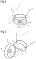
Figure 1 shows a view in perspective of the lower part of the food dispenser in closed condition. -
Figure 2 shows the lower part of the food dispenser in open position. -
Figure 3 shows a side view of the open food dispenser. -
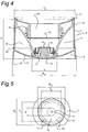
Figure 4 shows a section through the cap stand. -
Figure 5 shows a bottom view of the cap stand with dimensional details. -
Figure 6 shows a further embodiment of the cap stand. - Accordingly, the present invention provides a food dispenser comprising:
- a squeeze container holding a viscous food product, said squeeze container comprising a bottom opening;
- a non-transparent spout member connected to the lower end of the container over the bottom opening thereof, said spout member having a spout opening through which the viscous food product is discharged;
- a cap stand comprising a collar located around the spout member, a cap and a hinge that connects said cap to said collar, said cap stand being transferrable between a closed position in which the spout opening and the cap are closed, and an open position in which the spout opening and the cap are open for discharge of the viscous product, said cap having a foot so that a stable support is provided for the dispenser in the closed position of the cap;
- Usually, an annular chamber is defined between the spout member and the collar. The spout member is thus clearly visible within the annular chamber, whereby the egress of the food product is easily observed. For instance, a proper chamber is obtained in case the internal diameter of the bottom end of the collar is at least 2 times larger than the external diameter of the bottom end of the spout member. The spout member itself is non-transparent. The container may be either transparent or non-transparent.
- The collar may be partly transparent; for instance, at least 50% of the collar may be transparent. Preferably, at least 80% of the collar is transparent, more preferably at least 90% of the collar is transparent and most preferably the complete collar is transparent.
- In accordance with another preferred embodiment, the cap stand, including collar, cap and hinge, is transparent,
- In order to enable careful dosing of the viscous food product that is contained within the squeeze container the spout opening preferably has an internal diameter of less than 1 cm, even more preferably of less than 6 mm, most preferably of less than 4 mm. Typically, the spout opening has a diameter of at least 0.3 mm, even more preferably of at least 0.5 mm.
- After the food dispenser has been used several times, tiny rests of the food product might adhere to the outside of the spout opening. Such tiny amounts usually do not detract from the overall appearance of the food dispenser. However, it would be quite undesirable in case such amounts would drip further into the chamber and along the outside of the spout member, for instance as a result of an inverted position of the food dispenser. For the purpose of preventing such dripping to occur, a shield may provided within the annular chamber. This shield extends between the outside of the spout member and the inside of the collar, in such a way that possible drippings are prevented from entering the chamber. The shield may be located at the lowermost end of the collar and the spout, so as to achieve a maximal effect. Preferably, the shield is transparent as well.
- The container may comprise a neck surrounding the bottom opening thereof, in such a way that spout member and/or the collar may be detachably connected to the neck, e.g. by means of a screw connection. The cap stand may be connected to the container according to several possibilities. Preferably, the cap stand is connected to the spout member, such as by molding. The cap stand may be formed in one piece, such as by injection molding. Alternatively, the cap stand may be assembled from distinct parts, e.g. by gluing, welding and the like.
- The quality of the food product in the flexible container can be guaranteed by providing the bottom opening with a releasable seal. Preferably the seal is located between the neck and the spout member. The consumer removes this seal before use; to that end, the cap stand comprising the spout and cap can be removed from the container. After the seal has been released, the cap stand is put back on the flexible container.
- The cap stand may have any shape, for instance a cylindrical shape. In particular, the cap stand may have a non-cylindrical shape defined by mutually perpendicular top width dimensions T1, T2 and mutually perpendicular bottom width dimensions B1, B2, at least one of said top width dimensions being smaller than a corresponding one of said bottom width dimensions. The relatively wide bottom end of the cap stand and the correspondingly wide support face of the cap provide a stable support of the dispenser. Preferably, the ratio of a bottom width dimension B1, B2 to a corresponding top width dimension T1, T2 is in the range of 2:1 to 1.1:1. In case the top and bottom of the cap stand are circular (B1=B2, respectively T1=T2), the ratio of the top diameter and of the bottom diameter may be in the same range of 2:1 to 1.1:1. Alternatively, the bottom of the cap stand may also have a non-circular shape, such as oval or elliptical. Also, the top of the cap stand may have a non-circular shape, e.g. an oval shape or elliptical shape etc. The ratio of a bottom width dimension B1, B2 to height dimension H of the cap stand may be in the range of 1:1 to 3:1.
- The collar may have similar shapes as well. The top end of the collar may be narrower than the bottom end thereof. Also, the collar may have a circular or non-circular top end and bottom end.
- For the purpose of providing a proper connection between the cap, in the closed position thereof, and the collar, the cap may comprise an annular flange or rim that engages the bottom end of the collar in the closed position of the cap. Furthermore, the cap may comprise a stop that engages the spout opening in the closed position of said cap. The spout is thus closed as soon as the cap is transferred to the closed position.
- The food dispenser is preferably manufactured from a plastics material. In particular, the cap stand and the spout member consist of plastic material. The expression "transparent" as used before refers to the light transferring capacity of the material from which the collar has been manufactured. It will be understood that the best result for viewing the discharge of the food product is obtained in case said material is highly transparent. As an example, the cap stand material may transmit at least 60% or even at least 80% of the incident light. More preferably, at least 90 % of the incident light is transmitted, even more preferably at least 95% of the incident light is transmitted and most preferable at least 99% of the incident light is transmitted.
- It is pointed out that the bottom opening dispenser as discussed before may have text and image imprints on the outside thereof for customer information. Such imprints will be readily discernible in case the dispenser is oriented according to the nominal position with the bottom opening pointing downward. However, it is not excluded that the dispenser may also be oriented with the bottom opening pointing upward, for instance during transport or even in store or on display at the location of the retailer.
- The viscous food product comprised by the squeeze container typically has a viscosity at 20°C and a shear rate of 10 s-1 of at least 1.0 Pa.s. More preferably, the food product has viscosity under these conditions of at least 5.0 Pa.s, even more preferably of at least 8.0 Pa.s and most preferably of at least 10.0 Pa.s. Examples of viscous food products that may advantageously be packaged in the present dispenser include mayonnaise, ketchup and mustard.
- The invention will now be described further with reference to the embodiment of the food dispenser as shown in the drawings.
- The food dispenser as shown in the figures comprises a
squeeze container 1, preferably of a flexible plastic material, which has anupper wall 2 and acontainer neck 3 at the lower end. Onto theneck 3, aspout member 4 is mounted by means ofscrew threads 16 as shown in the section offigure 4 . Saidspout member 4 has a through going channel which at the upper end connects to anopening 14 in thecontainer neck 3 and which at the lower end has aspout opening 5. As shown infigure 4 , aplastic valve 18, e.g. from silicone, is applied on thespout opening 5. Thevalve 18 has aslit 19, which may be carried out as a cross shaped slit, through which the food product is discharged. - A
cap stand 6 is provided around thespout member 4. This cap stand 6 is transparent and consists of thecollar 7 and thecap 8. Thecollar 7 has an upper end which is connected to thespout member 4 through themould seam 17, and a lower end. Thespout member 4 protrudes downwardly into thecap stand 6, and in particular into thecollar 7 thereof. By means of theelastic hinge 9, thecap 8 is suspended from the lower end of thecollar 7. Thecap 8 has acap wall 11 and an uppercircumferential rim 10, which, in the closed position of thecap 8, engages the lower end of thecollar 7, e.g. by a click or snap fit connection. The lowercircumferential rim 23 of the cap forms a flat support of the dispenser, in the closed condition of thecap 8. - Furthermore, the cap has a
stop 12 at its inner surface. In the closed position of thecap 8, saidstop 12 engages thespout opening 5 of thespout member 6 so as to close the spout member and prevent the egress of the food product from the container. - At the free end of the
neck 3, aseal 15 has been applied for protection of the food product (not shown) in thecontainer 1 against quality loss, tampering etc. Before use, the seal has to be removed from the neck. To that end, thecap stand 6 together with thespout member 4 are unscrewed from theneck 3; after removal of the seal, the cap stand and spoutmember 4 are refitted onto theneck 3. - A
chamber 13 is defined between thespout member 4 and thecollar 7. Through the transparent material of thecollar 7, the consumer may easily observe thespout member 4 and the food product which is discharged from thespout member 4, thereby enabling a better control of the dispensing function. - The cap stand may be carried out in several shapes. The cap stand may for instance have a non-circular shape, with mutually perpendicular top dimensions T1 and T2 which are different from each other. Thus, the top may be for instance elliptical or oval and the like. Alternatively, the top dimensions T1 and T2 may be equal, such that the top of the cap stand is circular (see
figure 5 ). Furthermore, the mutually perpendicular bottom dimensions B1 and B2 may be different, for instance elliptical or oval and the like, or equal. Thecollar 7, as part of thecap stand 6, may have corresponding circular or non-circular shapes at its top end and bottom end as well. Furthermore, the top end of the collar may be narrower than the bottom end thereof. - In the embodiment of
figure 6 , atransparent shield 20 stretches between thespout member 4 and thecollar 7. Theouter boundary 22 of theshield 20 adjoins the inside of thecollar 7, and theinner boundary 21 of theshield 20 adjoins the outside of thespout member 4. Any drippings which might be collected near thespout opening 5 are thus prevented from entering thechamber 13 between thespout member 4 and thecollar 7. Thus, the overall appearance of the food dispenser will not be spoiled by rests of the food product which adhere to the outside of the spout member. In particular in case thespout member 4 is non transparent, the drippings will hardly be noticed near the spout
opening 5.
Claims (14)
- A food dispenser comprising:• a squeeze container (1) holding a viscous food product, said squeeze container (1) having a bottom opening (14);• a spout member (4) connected to the container (1) over the bottom opening (14) thereof, said spout member having a spout opening (5) through which the viscous food product is discharged;• a cap stand (6) comprising a collar (7) which is located around the spout member (4) and which is connected to the container (1) and/or the spout member (4), a cap (8) and a hinge (9) that connects said cap to said collar, said cap stand (6) being transferrable between a closed position in which the spout opening (5) and the cap (8) are closed, and an open position in which the spout opening (5) and the cap (8) are open for discharge of the viscous food product, and said cap (7) having a foot (11) so that a stable support is provided for the dispenser in the closed position of the cap (8),characterized in that at least a part of said collar (7) is transparent and the spout member is non-transparent so that a user can observe said discharge of viscous food product from the spout member (4).
- Food dispenser according to claim 1, wherein an annular chamber (13) is defined between the spout member (4) and the collar (7).
- Food dispenser according to claim 2, wherein a shield (20) is provided which extends between the spout member (4) and the collar (7).
- Food dispenser according to claim 3, wherein the shield (20) is located near or at the lower end of the collar (7), and the lower end of the spout member (4) protrudes through the shield.
- Food dispenser according to claim 3 or 4, wherein the shield (20) is transparent.
- Food dispenser according to claim 1, wherein the container (1) comprises a neck (3), the spout member (4) and/ or the collar (7) being detachably connected to the neck (3).
- Food dispenser according to claim 1, wherein the bottom opening (14) is closed by means of a releasable seal (15).
- Food dispenser according to claim 1, wherein the container (1) is non-transparent.
- Food dispenser according to claim 1, wherein at least 80% of the collar (7) is transparent.
- Food dispenser according to claim 1, wherein the cap stand (6) has mutually perpendicular top width dimensions T1, T2 and mutually perpendicular bottom width dimensions B1, B2, at least one of said top width dimensions being smaller than the corresponding bottom width dimension.
- Food dispenser according to claim 1, wherein the cap (8) comprises an annular flange or rim (10) that engages the bottom end of the collar (7) in the closed position of the cap (8).
- Food dispenser according to claim 1, wherein the cap (8) comprises a stop (12) that engages the spout opening in (5) the closed position of said cap (8).
- Food dispenser according to claim 1, wherein the spout member (4) protrudes beyond the bottom end of the collar (7).
- Food dispenser according to claim 1, wherein the light transfer capacity of the cap stand material is at least 90%, preferably at least 95%, most preferably at least 99%.
Applications Claiming Priority (2)
| Application Number | Priority Date | Filing Date | Title |
|---|---|---|---|
| US12/896,298 US20120080450A1 (en) | 2010-10-01 | 2010-10-01 | Food dispenser |
| PCT/EP2011/065745 WO2012041688A1 (en) | 2010-10-01 | 2011-09-12 | Food dispenser |
Publications (2)
| Publication Number | Publication Date |
|---|---|
| EP2621827A1 EP2621827A1 (en) | 2013-08-07 |
| EP2621827B1 true EP2621827B1 (en) | 2016-05-11 |
Family
ID=44651755
Family Applications (1)
| Application Number | Title | Priority Date | Filing Date |
|---|---|---|---|
| EP11757597.7A Active EP2621827B1 (en) | 2010-10-01 | 2011-09-12 | Food dispenser |
Country Status (12)
| Country | Link |
|---|---|
| US (1) | US20120080450A1 (en) |
| EP (1) | EP2621827B1 (en) |
| AR (1) | AR083265A1 (en) |
| BR (1) | BR112013007619B1 (en) |
| CA (1) | CA2812880C (en) |
| CL (1) | CL2013000867A1 (en) |
| DE (1) | DE202011106496U1 (en) |
| EA (1) | EA025312B1 (en) |
| ES (1) | ES2585327T3 (en) |
| MX (1) | MX2013003316A (en) |
| PL (1) | PL2621827T3 (en) |
| WO (1) | WO2012041688A1 (en) |
Families Citing this family (28)
| Publication number | Priority date | Publication date | Assignee | Title |
|---|---|---|---|---|
| US9433960B2 (en) * | 2008-09-01 | 2016-09-06 | Rieke Corporation | Liquid dosing devices |
| EP2475584A2 (en) * | 2009-09-11 | 2012-07-18 | Kraft Foods Global Brands LLC | Containers and methods for dispensing multiple doses of a concentrated liquid, and shelf stable concentrated liquids |
| BR112013004938B8 (en) | 2010-09-02 | 2020-10-13 | Kraft Foods Group Brands Llc | containers for dispensing beverage concentrates |
| US11013248B2 (en) | 2012-05-25 | 2021-05-25 | Kraft Foods Group Brands Llc | Shelf stable, concentrated, liquid flavorings and methods of preparing beverages with the concentrated liquid flavorings |
| AU346532S (en) | 2012-06-18 | 2013-01-23 | Unilever Plc | Bottle |
| AU347521S (en) * | 2012-06-18 | 2013-03-13 | Unilever Plc | Bottle cap |
| US20140263436A1 (en) * | 2013-03-15 | 2014-09-18 | Tc Heartland Llc | Container |
| US10518943B2 (en) | 2013-03-15 | 2019-12-31 | Tc Heartland Llc | Container with valve |
| EA029657B1 (en) | 2013-05-20 | 2018-04-30 | Юнилевер Н.В. | Process for coating containers |
| NL2011828C2 (en) * | 2013-11-21 | 2015-05-26 | Louis Rinze Henricus Adrianus Willemsen | CONTAINER FOR FISH SELECTION LIQUIDS, AND A METHOD FOR MANUFACTURING THEM. |
| USD742229S1 (en) * | 2014-03-19 | 2015-11-03 | Aptargroup, Inc. | Flared lid closure |
| GB201414603D0 (en) * | 2014-08-18 | 2014-10-01 | Obrist Closures Switzerland | Improvements in or relating to closures |
| US10131473B2 (en) * | 2015-02-23 | 2018-11-20 | Henkel IP & Holding GmbH | Inverted bottle dispensing systems and methods |
| GB201516189D0 (en) * | 2015-09-14 | 2015-10-28 | Obrist Closures Switzerland | Head stand closure with a tamper-evident seal |
| US10494164B2 (en) | 2016-03-09 | 2019-12-03 | Fifth Third Bank, an Ohio Banking | Dispensable containment vessel and dispensing system |
| NL2017159B1 (en) * | 2016-07-13 | 2018-01-18 | Weener Plastics Netherlands B V | Dispensing closure |
| USD871904S1 (en) | 2017-01-05 | 2020-01-07 | Silgan White Cap LLC | Closure |
| USD858307S1 (en) | 2018-05-21 | 2019-09-03 | Chobani, LLC | Squeezable container |
| US10399750B1 (en) | 2018-05-21 | 2019-09-03 | Chobani, LLC | Squeezable container |
| US11292642B2 (en) | 2018-12-21 | 2022-04-05 | H. J. Heinz Company Brands Llc | Container, closure, and methods for manufacture |
| MX2021007360A (en) | 2018-12-21 | 2021-12-15 | Heinz Co Brands H J Llc | Container, closure, and methods for manufacture. |
| USD889260S1 (en) | 2018-12-21 | 2020-07-07 | H.J. Heinz Company Brands Llc | Closure for a container |
| ES2900462T3 (en) * | 2019-01-24 | 2022-03-17 | Procter & Gamble | Inverted non-drip bottles |
| KR102848926B1 (en) | 2019-09-20 | 2025-08-20 | 에이치.제이.헤인즈 컴퍼니 브랜즈 엘엘씨 | Containers, closures, and methods of manufacturing |
| USD1095234S1 (en) | 2019-12-19 | 2025-09-30 | The Procter & Gamble Company | Bottom dispensing container |
| USD909878S1 (en) * | 2020-06-16 | 2021-02-09 | The Procter & Gamble Company | Bottom dispensing container |
| EP4217290A4 (en) | 2020-10-19 | 2024-03-13 | AptarGroup, Inc. | VALVE |
| FR3166617A1 (en) * | 2024-09-23 | 2026-03-27 | L'oreal | A sealing device for a product packaging and dispensing assembly, and a sealing assembly comprising such a device |
Citations (1)
| Publication number | Priority date | Publication date | Assignee | Title |
|---|---|---|---|---|
| US20030121876A1 (en) * | 2001-12-31 | 2003-07-03 | Pechiney Plastic Packaging, Inc. | Waterguard tube |
Family Cites Families (27)
| Publication number | Priority date | Publication date | Assignee | Title |
|---|---|---|---|---|
| US4723671A (en) * | 1986-10-01 | 1988-02-09 | Mears Gary L | Bottle cap stand |
| US4895282A (en) * | 1988-08-01 | 1990-01-23 | Owens-Illinois Closure Inc. | Dispensing closure with pull tab for enlarging orifice |
| GB8907814D0 (en) | 1989-04-06 | 1989-05-17 | Unilever Plc | Dispensing means |
| US5271531A (en) * | 1991-01-14 | 1993-12-21 | Seaquist Closures, A Division Of Pittway Corp. | Dispensing closure with pressure-actuated flexible valve |
| US5169035A (en) * | 1991-05-21 | 1992-12-08 | Seaquist Closures A Division Of Pittway Corporation | Squeeze bottle dispensing closure with vent valve |
| US5263787A (en) * | 1992-05-22 | 1993-11-23 | The Flagship Group, Inc. | Inverted cap for craft paint applicators |
| US5460298A (en) * | 1992-12-28 | 1995-10-24 | Dibiase; Anthony E. | Stand for container inversion |
| US5292035A (en) * | 1993-02-22 | 1994-03-08 | Millar David R | Reusable dispensing cap |
| US5386918A (en) * | 1993-04-22 | 1995-02-07 | Colgate-Palmolive Co. | Closure with tamper evidence structure |
| US5626262A (en) * | 1995-06-07 | 1997-05-06 | Redmond Products, Inc. | Dispensing container with drainage passages |
| US5680969A (en) * | 1995-12-18 | 1997-10-28 | Aptargroup, Inc. | Closure with dispensing valve and separate releasable internal shipping seal |
| US5927566A (en) * | 1996-07-11 | 1999-07-27 | Aptargroup, Inc. | One-piece dispensing system and method for making same |
| US6045004A (en) * | 1998-03-20 | 2000-04-04 | Aptargroup, Inc. | Dispensing structure with dispensing valve and barrier penetrator |
| FR2810641B1 (en) * | 2000-06-21 | 2002-10-18 | Cebal | FLEXIBLE TUBE PROVIDED WITH A LARGE DIAMETER NECK AND RIGID TIP TO BE FIXED ON SAID TUBE |
| US6705492B2 (en) * | 2002-06-27 | 2004-03-16 | Method Products, Inc. | Bottom-dispensing liquid soap dispenser |
| CA2406986A1 (en) * | 2002-10-08 | 2004-04-08 | Garth Rowswell | Inverted bottle cap |
| PL1622814T3 (en) * | 2003-05-07 | 2008-07-31 | Obrist Closures Switzerland | Valve closure |
| DE10327974A1 (en) * | 2003-06-21 | 2005-01-13 | Alfred Von Schuckmann | Dispenser for liquid adhesive has squeeze container with mouth opening and applicator surface covered by movable membrane moving back from wide surface application to spot application position |
| KR100561958B1 (en) * | 2003-06-30 | 2006-03-21 | 주식회사 종우실업 | Dispensing enclosure with integral self-sealing valve |
| US7255250B2 (en) * | 2004-06-22 | 2007-08-14 | Owens-Illinois Closure Inc. | Dispensing closure, package and method of manufacture |
| CN101119900A (en) * | 2004-12-23 | 2008-02-06 | 爱博克斯(C.I.)有限公司(湾景信托公司托管人) | Flanges for tamper evident closures and container necks |
| US7503469B2 (en) * | 2005-03-09 | 2009-03-17 | Rexam Closure Systems Inc. | Integrally molded dispensing valve and method of manufacture |
| US7195138B2 (en) * | 2005-08-25 | 2007-03-27 | Continental Afa Dispensing Company | Container closure with biased closed valve |
| US20080029548A1 (en) * | 2006-05-05 | 2008-02-07 | Ann De Wree | Fabric treatment dispensing package |
| US20070270325A1 (en) | 2006-05-05 | 2007-11-22 | De Buzzaccarini Francesco | Gel compositions contained in bottom dispensing containers |
| US7850043B2 (en) * | 2006-08-09 | 2010-12-14 | Replenish Bottling, Llc | Refillable/reusable mixer container and method of using same |
| US8397956B2 (en) * | 2007-03-27 | 2013-03-19 | Aptargroup, Inc. | Dispensing valve with improved dispensing |
-
2010
- 2010-10-01 US US12/896,298 patent/US20120080450A1/en not_active Abandoned
-
2011
- 2011-09-12 BR BR112013007619-4A patent/BR112013007619B1/en active IP Right Grant
- 2011-09-12 MX MX2013003316A patent/MX2013003316A/en unknown
- 2011-09-12 EA EA201390502A patent/EA025312B1/en not_active IP Right Cessation
- 2011-09-12 ES ES11757597.7T patent/ES2585327T3/en active Active
- 2011-09-12 EP EP11757597.7A patent/EP2621827B1/en active Active
- 2011-09-12 CA CA2812880A patent/CA2812880C/en active Active
- 2011-09-12 PL PL11757597.7T patent/PL2621827T3/en unknown
- 2011-09-12 WO PCT/EP2011/065745 patent/WO2012041688A1/en not_active Ceased
- 2011-09-29 DE DE202011106496U patent/DE202011106496U1/en not_active Expired - Lifetime
- 2011-09-30 AR ARP110103628A patent/AR083265A1/en active IP Right Grant
-
2013
- 2013-03-28 CL CL2013000867A patent/CL2013000867A1/en unknown
Patent Citations (1)
| Publication number | Priority date | Publication date | Assignee | Title |
|---|---|---|---|---|
| US20030121876A1 (en) * | 2001-12-31 | 2003-07-03 | Pechiney Plastic Packaging, Inc. | Waterguard tube |
Also Published As
| Publication number | Publication date |
|---|---|
| AR083265A1 (en) | 2013-02-13 |
| PL2621827T3 (en) | 2016-11-30 |
| CA2812880A1 (en) | 2012-04-05 |
| CL2013000867A1 (en) | 2013-12-20 |
| BR112013007619A2 (en) | 2018-05-02 |
| MX2013003316A (en) | 2013-04-29 |
| ES2585327T3 (en) | 2016-10-05 |
| WO2012041688A1 (en) | 2012-04-05 |
| DE202011106496U1 (en) | 2011-11-11 |
| CA2812880C (en) | 2019-08-20 |
| EA025312B1 (en) | 2016-12-30 |
| BR112013007619B1 (en) | 2021-03-02 |
| EA201390502A1 (en) | 2013-07-30 |
| EP2621827A1 (en) | 2013-08-07 |
| US20120080450A1 (en) | 2012-04-05 |
Similar Documents
| Publication | Publication Date | Title |
|---|---|---|
| CA2812880C (en) | Food dispenser | |
| US5667107A (en) | Cover and stand for squeeze container with bottom outlet for dispensing viscous fluids | |
| US5131566A (en) | Flowable product package incorporating a refill facilitating pouring spout | |
| US20090242588A1 (en) | Squeeze bottle and pump combination | |
| EP0591601A1 (en) | Squirt dispenser for toilet bowl cleaner with improved coverage under the toilet bowl rim | |
| MX2014010900A (en) | Container closure for vented pouring through a curved aperture. | |
| EP3507204B1 (en) | A bottle pourer | |
| US8020696B2 (en) | Device and method for storing and mixing at least two materials | |
| US9452868B2 (en) | Device for pouring liquid contained in a container | |
| US4003503A (en) | Dispensing device for highly viscous liquids supported in inclined position | |
| US20140299629A1 (en) | Condiment dispener | |
| GB2333086A (en) | Liquid dispenser | |
| EP2043923B1 (en) | Liquid container system | |
| US12534246B2 (en) | Refill system and spout and methods of using the same | |
| JP2013071744A (en) | Dripping container with applicator | |
| US20050194398A1 (en) | Container fitment comprising a dispensing orifice, and method of making the same | |
| EP4605143A1 (en) | Fluid transfer device | |
| EP1535854A1 (en) | Cap for containers with cover lid rotating on a transverse horizontal axis snap activated by pushing with a finger or thumb | |
| JP6108456B2 (en) | Hinge cap with weighing function | |
| JP6777424B2 (en) | Container with weighing device | |
| GB2344808A (en) | Container with a dispensing opening | |
| EP2857328B1 (en) | Small food storage container | |
| WO2006079771A1 (en) | Gravity fuelled fluid dispenser | |
| CA3039002C (en) | Plastic container with integrated spout for directional pour | |
| CA3025984C (en) | Controllable power and lighting system |
Legal Events
| Date | Code | Title | Description |
|---|---|---|---|
| PUAI | Public reference made under article 153(3) epc to a published international application that has entered the european phase |
Free format text: ORIGINAL CODE: 0009012 |
|
| 17P | Request for examination filed |
Effective date: 20130307 |
|
| AK | Designated contracting states |
Kind code of ref document: A1 Designated state(s): AL AT BE BG CH CY CZ DE DK EE ES FI FR GB GR HR HU IE IS IT LI LT LU LV MC MK MT NL NO PL PT RO RS SE SI SK SM TR |
|
| DAX | Request for extension of the european patent (deleted) | ||
| 17Q | First examination report despatched |
Effective date: 20150513 |
|
| GRAP | Despatch of communication of intention to grant a patent |
Free format text: ORIGINAL CODE: EPIDOSNIGR1 |
|
| INTG | Intention to grant announced |
Effective date: 20160111 |
|
| RIN1 | Information on inventor provided before grant (corrected) |
Inventor name: SHOEMAKER, JAMES, A Inventor name: DZIERSK, MARK, DIETER Inventor name: CURRAT, OLIVIER, FRANCK Inventor name: BOER, HARRY, EVERT |
|
| GRAS | Grant fee paid |
Free format text: ORIGINAL CODE: EPIDOSNIGR3 |
|
| GRAA | (expected) grant |
Free format text: ORIGINAL CODE: 0009210 |
|
| AK | Designated contracting states |
Kind code of ref document: B1 Designated state(s): AL AT BE BG CH CY CZ DE DK EE ES FI FR GB GR HR HU IE IS IT LI LT LU LV MC MK MT NL NO PL PT RO RS SE SI SK SM TR |
|
| REG | Reference to a national code |
Ref country code: GB Ref legal event code: FG4D |
|
| REG | Reference to a national code |
Ref country code: CH Ref legal event code: EP |
|
| REG | Reference to a national code |
Ref country code: AT Ref legal event code: REF Ref document number: 798469 Country of ref document: AT Kind code of ref document: T Effective date: 20160515 |
|
| REG | Reference to a national code |
Ref country code: IE Ref legal event code: FG4D Ref country code: NL Ref legal event code: FP |
|
| REG | Reference to a national code |
Ref country code: DE Ref legal event code: R096 Ref document number: 602011026484 Country of ref document: DE |
|
| REG | Reference to a national code |
Ref country code: LT Ref legal event code: MG4D |
|
| REG | Reference to a national code |
Ref country code: FR Ref legal event code: PLFP Year of fee payment: 6 |
|
| REG | Reference to a national code |
Ref country code: ES Ref legal event code: FG2A Ref document number: 2585327 Country of ref document: ES Kind code of ref document: T3 Effective date: 20161005 |
|
| PG25 | Lapsed in a contracting state [announced via postgrant information from national office to epo] |
Ref country code: LT Free format text: LAPSE BECAUSE OF FAILURE TO SUBMIT A TRANSLATION OF THE DESCRIPTION OR TO PAY THE FEE WITHIN THE PRESCRIBED TIME-LIMIT Effective date: 20160511 Ref country code: FI Free format text: LAPSE BECAUSE OF FAILURE TO SUBMIT A TRANSLATION OF THE DESCRIPTION OR TO PAY THE FEE WITHIN THE PRESCRIBED TIME-LIMIT Effective date: 20160511 Ref country code: NO Free format text: LAPSE BECAUSE OF FAILURE TO SUBMIT A TRANSLATION OF THE DESCRIPTION OR TO PAY THE FEE WITHIN THE PRESCRIBED TIME-LIMIT Effective date: 20160811 |
|
| REG | Reference to a national code |
Ref country code: AT Ref legal event code: MK05 Ref document number: 798469 Country of ref document: AT Kind code of ref document: T Effective date: 20160511 |
|
| PG25 | Lapsed in a contracting state [announced via postgrant information from national office to epo] |
Ref country code: SE Free format text: LAPSE BECAUSE OF FAILURE TO SUBMIT A TRANSLATION OF THE DESCRIPTION OR TO PAY THE FEE WITHIN THE PRESCRIBED TIME-LIMIT Effective date: 20160511 Ref country code: HR Free format text: LAPSE BECAUSE OF FAILURE TO SUBMIT A TRANSLATION OF THE DESCRIPTION OR TO PAY THE FEE WITHIN THE PRESCRIBED TIME-LIMIT Effective date: 20160511 Ref country code: PT Free format text: LAPSE BECAUSE OF FAILURE TO SUBMIT A TRANSLATION OF THE DESCRIPTION OR TO PAY THE FEE WITHIN THE PRESCRIBED TIME-LIMIT Effective date: 20160912 Ref country code: LV Free format text: LAPSE BECAUSE OF FAILURE TO SUBMIT A TRANSLATION OF THE DESCRIPTION OR TO PAY THE FEE WITHIN THE PRESCRIBED TIME-LIMIT Effective date: 20160511 Ref country code: GR Free format text: LAPSE BECAUSE OF FAILURE TO SUBMIT A TRANSLATION OF THE DESCRIPTION OR TO PAY THE FEE WITHIN THE PRESCRIBED TIME-LIMIT Effective date: 20160812 Ref country code: RS Free format text: LAPSE BECAUSE OF FAILURE TO SUBMIT A TRANSLATION OF THE DESCRIPTION OR TO PAY THE FEE WITHIN THE PRESCRIBED TIME-LIMIT Effective date: 20160511 |
|
| PG25 | Lapsed in a contracting state [announced via postgrant information from national office to epo] |
Ref country code: EE Free format text: LAPSE BECAUSE OF FAILURE TO SUBMIT A TRANSLATION OF THE DESCRIPTION OR TO PAY THE FEE WITHIN THE PRESCRIBED TIME-LIMIT Effective date: 20160511 Ref country code: CZ Free format text: LAPSE BECAUSE OF FAILURE TO SUBMIT A TRANSLATION OF THE DESCRIPTION OR TO PAY THE FEE WITHIN THE PRESCRIBED TIME-LIMIT Effective date: 20160511 Ref country code: SK Free format text: LAPSE BECAUSE OF FAILURE TO SUBMIT A TRANSLATION OF THE DESCRIPTION OR TO PAY THE FEE WITHIN THE PRESCRIBED TIME-LIMIT Effective date: 20160511 Ref country code: DK Free format text: LAPSE BECAUSE OF FAILURE TO SUBMIT A TRANSLATION OF THE DESCRIPTION OR TO PAY THE FEE WITHIN THE PRESCRIBED TIME-LIMIT Effective date: 20160511 Ref country code: RO Free format text: LAPSE BECAUSE OF FAILURE TO SUBMIT A TRANSLATION OF THE DESCRIPTION OR TO PAY THE FEE WITHIN THE PRESCRIBED TIME-LIMIT Effective date: 20160511 |
|
| REG | Reference to a national code |
Ref country code: DE Ref legal event code: R097 Ref document number: 602011026484 Country of ref document: DE |
|
| PG25 | Lapsed in a contracting state [announced via postgrant information from national office to epo] |
Ref country code: SM Free format text: LAPSE BECAUSE OF FAILURE TO SUBMIT A TRANSLATION OF THE DESCRIPTION OR TO PAY THE FEE WITHIN THE PRESCRIBED TIME-LIMIT Effective date: 20160511 Ref country code: AT Free format text: LAPSE BECAUSE OF FAILURE TO SUBMIT A TRANSLATION OF THE DESCRIPTION OR TO PAY THE FEE WITHIN THE PRESCRIBED TIME-LIMIT Effective date: 20160511 Ref country code: BE Free format text: LAPSE BECAUSE OF NON-PAYMENT OF DUE FEES Effective date: 20160511 |
|
| PLBE | No opposition filed within time limit |
Free format text: ORIGINAL CODE: 0009261 |
|
| STAA | Information on the status of an ep patent application or granted ep patent |
Free format text: STATUS: NO OPPOSITION FILED WITHIN TIME LIMIT |
|
| 26N | No opposition filed |
Effective date: 20170214 |
|
| PG25 | Lapsed in a contracting state [announced via postgrant information from national office to epo] |
Ref country code: MC Free format text: LAPSE BECAUSE OF FAILURE TO SUBMIT A TRANSLATION OF THE DESCRIPTION OR TO PAY THE FEE WITHIN THE PRESCRIBED TIME-LIMIT Effective date: 20160511 |
|
| REG | Reference to a national code |
Ref country code: CH Ref legal event code: PL |
|
| PG25 | Lapsed in a contracting state [announced via postgrant information from national office to epo] |
Ref country code: SI Free format text: LAPSE BECAUSE OF FAILURE TO SUBMIT A TRANSLATION OF THE DESCRIPTION OR TO PAY THE FEE WITHIN THE PRESCRIBED TIME-LIMIT Effective date: 20160511 |
|
| REG | Reference to a national code |
Ref country code: IE Ref legal event code: MM4A |
|
| PG25 | Lapsed in a contracting state [announced via postgrant information from national office to epo] |
Ref country code: IE Free format text: LAPSE BECAUSE OF NON-PAYMENT OF DUE FEES Effective date: 20160912 Ref country code: LI Free format text: LAPSE BECAUSE OF NON-PAYMENT OF DUE FEES Effective date: 20160930 Ref country code: CH Free format text: LAPSE BECAUSE OF NON-PAYMENT OF DUE FEES Effective date: 20160930 |
|
| PG25 | Lapsed in a contracting state [announced via postgrant information from national office to epo] |
Ref country code: LU Free format text: LAPSE BECAUSE OF NON-PAYMENT OF DUE FEES Effective date: 20160912 |
|
| REG | Reference to a national code |
Ref country code: FR Ref legal event code: PLFP Year of fee payment: 7 |
|
| PG25 | Lapsed in a contracting state [announced via postgrant information from national office to epo] |
Ref country code: CY Free format text: LAPSE BECAUSE OF FAILURE TO SUBMIT A TRANSLATION OF THE DESCRIPTION OR TO PAY THE FEE WITHIN THE PRESCRIBED TIME-LIMIT Effective date: 20160511 Ref country code: HU Free format text: LAPSE BECAUSE OF FAILURE TO SUBMIT A TRANSLATION OF THE DESCRIPTION OR TO PAY THE FEE WITHIN THE PRESCRIBED TIME-LIMIT; INVALID AB INITIO Effective date: 20110912 |
|
| PG25 | Lapsed in a contracting state [announced via postgrant information from national office to epo] |
Ref country code: MK Free format text: LAPSE BECAUSE OF FAILURE TO SUBMIT A TRANSLATION OF THE DESCRIPTION OR TO PAY THE FEE WITHIN THE PRESCRIBED TIME-LIMIT Effective date: 20160511 Ref country code: MT Free format text: LAPSE BECAUSE OF NON-PAYMENT OF DUE FEES Effective date: 20160930 Ref country code: IS Free format text: LAPSE BECAUSE OF FAILURE TO SUBMIT A TRANSLATION OF THE DESCRIPTION OR TO PAY THE FEE WITHIN THE PRESCRIBED TIME-LIMIT Effective date: 20160511 |
|
| PG25 | Lapsed in a contracting state [announced via postgrant information from national office to epo] |
Ref country code: BG Free format text: LAPSE BECAUSE OF FAILURE TO SUBMIT A TRANSLATION OF THE DESCRIPTION OR TO PAY THE FEE WITHIN THE PRESCRIBED TIME-LIMIT Effective date: 20160511 |
|
| REG | Reference to a national code |
Ref country code: FR Ref legal event code: PLFP Year of fee payment: 8 |
|
| PG25 | Lapsed in a contracting state [announced via postgrant information from national office to epo] |
Ref country code: AL Free format text: LAPSE BECAUSE OF FAILURE TO SUBMIT A TRANSLATION OF THE DESCRIPTION OR TO PAY THE FEE WITHIN THE PRESCRIBED TIME-LIMIT Effective date: 20160511 |
|
| REG | Reference to a national code |
Ref country code: DE Ref legal event code: R081 Ref document number: 602011026484 Country of ref document: DE Owner name: UNILEVER IP HOLDINGS B.V., NL Free format text: FORMER OWNER: UNILEVER N.V., ROTTERDAM, NL |
|
| REG | Reference to a national code |
Ref country code: NL Ref legal event code: PD Owner name: UNILEVER IP HOLDINGS B.V.; NL Free format text: DETAILS ASSIGNMENT: CHANGE OF OWNER(S), ASSIGNMENT; FORMER OWNER NAME: UNILEVER N.V. Effective date: 20210413 |
|
| REG | Reference to a national code |
Ref country code: GB Ref legal event code: 732E Free format text: REGISTERED BETWEEN 20211125 AND 20211201 |
|
| REG | Reference to a national code |
Ref country code: ES Ref legal event code: PC2A Owner name: UNILEVER IP HOLDINGS B.V. Effective date: 20211228 |
|
| P01 | Opt-out of the competence of the unified patent court (upc) registered |
Effective date: 20230501 |
|
| PGFP | Annual fee paid to national office [announced via postgrant information from national office to epo] |
Ref country code: TR Payment date: 20230911 Year of fee payment: 13 |
|
| PGFP | Annual fee paid to national office [announced via postgrant information from national office to epo] |
Ref country code: PL Payment date: 20230901 Year of fee payment: 13 |
|
| PGFP | Annual fee paid to national office [announced via postgrant information from national office to epo] |
Ref country code: DE Payment date: 20250919 Year of fee payment: 15 |
|
| PGFP | Annual fee paid to national office [announced via postgrant information from national office to epo] |
Ref country code: IT Payment date: 20250919 Year of fee payment: 15 Ref country code: NL Payment date: 20250918 Year of fee payment: 15 |
|
| PGFP | Annual fee paid to national office [announced via postgrant information from national office to epo] |
Ref country code: GB Payment date: 20250918 Year of fee payment: 15 |
|
| PGFP | Annual fee paid to national office [announced via postgrant information from national office to epo] |
Ref country code: FR Payment date: 20250922 Year of fee payment: 15 |
|
| PGFP | Annual fee paid to national office [announced via postgrant information from national office to epo] |
Ref country code: ES Payment date: 20251028 Year of fee payment: 15 |
|
| PG25 | Lapsed in a contracting state [announced via postgrant information from national office to epo] |
Ref country code: PL Free format text: LAPSE BECAUSE OF NON-PAYMENT OF DUE FEES Effective date: 20240912 |