EP2621619B1 - Method of mixing - Google Patents
Method of mixing Download PDFInfo
- Publication number
- EP2621619B1 EP2621619B1 EP11751555.1A EP11751555A EP2621619B1 EP 2621619 B1 EP2621619 B1 EP 2621619B1 EP 11751555 A EP11751555 A EP 11751555A EP 2621619 B1 EP2621619 B1 EP 2621619B1
- Authority
- EP
- European Patent Office
- Prior art keywords
- container
- viscous material
- predispersion
- rpet
- mixing
- Prior art date
- Legal status (The legal status is an assumption and is not a legal conclusion. Google has not performed a legal analysis and makes no representation as to the accuracy of the status listed.)
- Not-in-force
Links
Images


Classifications
-
- B—PERFORMING OPERATIONS; TRANSPORTING
- B01—PHYSICAL OR CHEMICAL PROCESSES OR APPARATUS IN GENERAL
- B01F—MIXING, e.g. DISSOLVING, EMULSIFYING OR DISPERSING
- B01F35/00—Accessories for mixers; Auxiliary operations or auxiliary devices; Parts or details of general application
- B01F35/75—Discharge mechanisms
- B01F35/754—Discharge mechanisms characterised by the means for discharging the components from the mixer
-
- B—PERFORMING OPERATIONS; TRANSPORTING
- B01—PHYSICAL OR CHEMICAL PROCESSES OR APPARATUS IN GENERAL
- B01F—MIXING, e.g. DISSOLVING, EMULSIFYING OR DISPERSING
- B01F23/00—Mixing according to the phases to be mixed, e.g. dispersing or emulsifying
- B01F23/50—Mixing liquids with solids
- B01F23/57—Mixing high-viscosity liquids with solids
-
- B—PERFORMING OPERATIONS; TRANSPORTING
- B01—PHYSICAL OR CHEMICAL PROCESSES OR APPARATUS IN GENERAL
- B01F—MIXING, e.g. DISSOLVING, EMULSIFYING OR DISPERSING
- B01F27/00—Mixers with rotary stirring devices in fixed receptacles; Kneaders
- B01F27/60—Mixers with rotary stirring devices in fixed receptacles; Kneaders with stirrers rotating about a horizontal or inclined axis
- B01F27/72—Mixers with rotary stirring devices in fixed receptacles; Kneaders with stirrers rotating about a horizontal or inclined axis with helices or sections of helices
- B01F27/721—Mixers with rotary stirring devices in fixed receptacles; Kneaders with stirrers rotating about a horizontal or inclined axis with helices or sections of helices with two or more helices in the same receptacle
- B01F27/723—Mixers with rotary stirring devices in fixed receptacles; Kneaders with stirrers rotating about a horizontal or inclined axis with helices or sections of helices with two or more helices in the same receptacle the helices intermeshing to knead the mixture
-
- B—PERFORMING OPERATIONS; TRANSPORTING
- B01—PHYSICAL OR CHEMICAL PROCESSES OR APPARATUS IN GENERAL
- B01F—MIXING, e.g. DISSOLVING, EMULSIFYING OR DISPERSING
- B01F35/00—Accessories for mixers; Auxiliary operations or auxiliary devices; Parts or details of general application
- B01F35/75—Discharge mechanisms
-
- B—PERFORMING OPERATIONS; TRANSPORTING
- B29—WORKING OF PLASTICS; WORKING OF SUBSTANCES IN A PLASTIC STATE IN GENERAL
- B29B—PREPARATION OR PRETREATMENT OF THE MATERIAL TO BE SHAPED; MAKING GRANULES OR PREFORMS; RECOVERY OF PLASTICS OR OTHER CONSTITUENTS OF WASTE MATERIAL CONTAINING PLASTICS
- B29B7/00—Mixing; Kneading
- B29B7/80—Component parts, details or accessories; Auxiliary operations
- B29B7/802—Constructions or methods for cleaning the mixing or kneading device
- B29B7/803—Cleaning of mixers of the gun type, stream-impigement type, mixing heads
- B29B7/806—Cleaning of the discharge opening, e.g. orifice of the dispenser
-
- C—CHEMISTRY; METALLURGY
- C08—ORGANIC MACROMOLECULAR COMPOUNDS; THEIR PREPARATION OR CHEMICAL WORKING-UP; COMPOSITIONS BASED THEREON
- C08G—MACROMOLECULAR COMPOUNDS OBTAINED OTHERWISE THAN BY REACTIONS ONLY INVOLVING UNSATURATED CARBON-TO-CARBON BONDS
- C08G85/00—General processes for preparing compounds provided for in this subclass
- C08G85/004—Modification of polymers by chemical after-treatment
-
- B—PERFORMING OPERATIONS; TRANSPORTING
- B01—PHYSICAL OR CHEMICAL PROCESSES OR APPARATUS IN GENERAL
- B01F—MIXING, e.g. DISSOLVING, EMULSIFYING OR DISPERSING
- B01F2101/00—Mixing characterised by the nature of the mixed materials or by the application field
- B01F2101/2805—Mixing plastics, polymer material ingredients, monomers or oligomers
Definitions
- the invention generally relates to a method of substantially homogeneously mixing ingredients comprising solid particulates and a viscous material in a container.
- Poly(ethylene terephthalate) (PET or polyethylene terephthalate) has many uses such as, for example, for making synthetic fibers and food-grade containers (e.g., beverage bottles).
- United States Patent Number US 7,297,721 B2 ; PCT International Patent Application Publication Number WO 98/41375 A ; and Japanese Patent Application Number JP H10-101784 A all mention using homogeneous mixtures of recycled poly(ethylene terephthalate) (RPET) and poly(ethylene terephthalate) (PET) monomers comprising terephthalic acid (TPA) and monoethylene glycol (MEG) in processes to manufacture PET.
- RPET poly(ethylene terephthalate)
- PET poly(ethylene terephthalate) monomers comprising terephthalic acid (TPA) and monoethylene glycol (MEG) in processes to manufacture PET.
- TPA terephthalic acid
- MEG monoethylene glycol
- the process adds RPET as a melt or a solid to an esterification reactor containing a melt of PET precursors.
- the added solid RPET melts in the esterification reactor before fully mixing with the PET precursors.
- the process melts RPET in an extruder, and then adds the melted RPET to an esterification reactor.
- the JP H10-101784 A process separately adds a slurry of TPA and MEG to the esterification reactor.
- RPET gradually decomposes when it is near or above its melting temperature (e.g., RPET flakes melt at about 245 degrees Celsius). If left unchecked, melted RPET will decompose to an extent that it would become unsuitable for preparing food-grade PET.
- the inventors have recognized that the prior art requirement of first melting RPET solids before the RPET can form homogeneous mixtures with PET monomers is a deficiency of the prior art processes in view of the thermal decomposition liability of RPET. Accordingly, the inventors sought to reduce the period of time RPET spends in a melt phase but not also in homogeneous admixture with MEG during manufacturing of PET. At the esterification stage of PET manufacturing in particular, the inventors sought to reduce how long RPET would be exposed to decomposition conditions without also being intimately exposed to the full transesterifying affect of MEG. They desired a flexible solution in order to achieve this advantage without altering their esterification reaction conditions, since these had been optimized for production of food-grade PET. For example, the inventors desired to maintain the same reaction temperature and avoid using any solvent in their esterification reactor.
- the inventors describe herein a solution to the problem of mixing ingredients comprising RPET flakes and a paste comprising TPA and MEG in an esterification reactor in a reduced period of time compared to period of time for melting one or both of the ingredients and mixing them together.
- the inventors' solution comprises feeding a modified phase of RPET flakes into the esterification reactor.
- the modified phase of RPET flakes comprises a substantially homogeneous predispersion comprising the RPET flakes and a major portion of the paste.
- the solution also comprises separately feeding the remaining portion (i.e., minor portion) of the paste into the esterification reactor.
- the predispersion and remaining portion feeds enter the esterification reactor via a same inlet or different inlets thereof.
- the paste comprises an excess quantity of MEG (or, e.g., MEG and diethylene glycol (DEG)) capable of rapidly transesterifying substantially all of the RPET, preferably so as to produce ethylene terephthalate oligomers and proportionately reduce or prevent thermal decomposition of the RPET.
- MEG or, e.g., MEG and diethylene glycol (DEG)
- DEG diethylene glycol
- the substantially homogeneous predispersion of RPET flakes provides the RPET with exposure to substantially full transesterifying effect of MEG even before the RPET is melted and does not require altering of their esterification reaction conditions.
- the paste and modified phase of RPET flakes further comprise isophthalic acid (IPA), a polycondensation catalyst, and diethylene glycol (DEG).
- IPA isophthalic acid
- DEG diethylene glycol
- the polycondensation catalyst means a substance effective for catalyzing an esterification reaction, transesterification reaction, or preferably esterification and transesterification reactions.
- the solution also advantageously produces a homogeneous mixture of RPET and ethylene terephthalate oligomers (described later) in the esterification reactor in significantly less time, with significantly less decomposition of the RPET, or both compared to period of time for melting the RPET flakes and fully mixing them and the PET monomers together in the esterification reactor.
- the inventors solution can be used in continuous feed and batch fed processes. Further, the inventors discovered that their solution can be applied to the mixing of any solid thermoplastic particulates, not just RPET flakes, with any viscous material containing the sufficient excess quantify of a reactant for the solid thermoplastic particulate as described later, not just the paste comprising MEG.
- the invention is especially valuable for, and in some embodiments, comprises, mixing the reactant(s) with solid thermoplastic particulates that contain a thermoplastic material that is prone to thermal decomposition (under the circumstances), wherein the mixing is done in such a way that the reactant can react with the thermoplastic material and reduce the thermal decomposition thereof.
- the solid thermoplastic particulates are aromatic polyester resin particulates, and more preferably PET resins.
- the inventors discovered a problem when they tried to continuously feed a homogeneous paste comprising RPET flakes, TPA, and MEG, and preferably further comprising the IPA, polycondensation catalyst, and DEG, from a Segler double shaft screw blender containing a single cone-shaped discharge portion containing two outlets.
- the paste clogged the outlets of the Segler double shaft screw blender.
- the inventors discovered that hot MEG vapor promptly initiated decomposing of the paste and caused bridging with unmelted RPET flakes, resulting in agglomerated RPET flakes clogging paste feed lines.
- the inventors solution generally comprises replacing the single cone-shaped discharge portion of the Segler double shaft screw blender with a plurality of smaller sized discharge cones as described later so as to enable clog-free operation of the resulting modified apparatus under the circumstance. Further, the inventors discovered that the modification can be applied to any container in need of a discharge portion, especially one in need of a clog-free discharge portion.
- the present invention provides a method of mixing ingredients comprising solid thermoplastic particulates and a viscous material in a first container without first melting the solid thermoplastic particulates, the method comprising feeding a predispersion comprising a substantially homogeneous mixture of the solid thermoplastic particulates and a major portion of the viscous material and feeding the remaining minor portion of the viscous material into the first container to give added ingredients in the first container; and mixing the added ingredients in the first container, wherein the solid thermoplastic particulates comprises a thermoplastic material and the major portion of the viscous material comprises a sufficient excess quantity of a reactant for the thermoplastic material.
- the solid thermoplastic particulates are MET particulates.
- the RPET particulates are RPET pellets or, more preferably, RPET flakes.
- the method of the present invention may employ a device for discharging a material from a second container without the material clogging the device, the device comprising a plurality of discharge cons; wherein each discharge cone has spaced-apart upstream and downstream apertures in fluid communication with each other, diameter of the upstream aperture being at most 4 times larger than diameter of the downstream aperture; wherein each discharge cone independently defines a volumetric space between the upstream and downstream apertures that is dimensioned and configured for containing a non-clogging amount of the material; and wherein each discharge cone independently is adapted for receiving the non-clogging amount of the material into the volumetric space through the upstream aperture and discharging the non-clogging amount of the material out of the volumetric space through the downstream aperture without clogging the device.
- the device further comprises the second container and is in operative connection to the second container in such a way that a material contained in the second container can be discharged therefrom via the device without clogging the device.
- the method of the present invention may also employ an apparatus for mixing a material, wherein the apparatus comprises the device as in the second embodiment and a mixing portion (e.g., twin screw conveyor/mixer) comprising a second container; wherein the second container has a downstream outlet defining an opening and is sealably connected to the device around and proximal to the upstream apertures of the device in such a way that the device restricts the opening of the downstream outlet of the second container to the openings of the upstream apertures of the device; and the apparatus functions in such a way that when the second container of the apparatus contains a material, the material can be discharged from the apparatus via the device without clogging the device.
- a mixing portion e.g., twin screw conveyor/mixer
- the invention method is useful for preparing the predispersion and adding it into the first container (e.g., an esterification reactor) and thereby exposing RPET to substantially full transesterifying effect of MEG even before the RPET is melted.
- the invention method can be adapted to current manufacturing processes and does not require altering their esterification reaction conditions.
- the invention method reduces period of time RPET spends in a melt phase at high temperature (e.g., > 200 °C) but not also in admixture with MEG during manufacturing of PET.
- the iinvention method reduces how long RPET would be exposed to decomposition conditions without also being exposed to the transesterifying affect of MEG.
- the invention method is also useful for producing a homogeneous mixture of ingredients comprising the solid thermoplastic particulates (e.g., RPET flakes) and the viscous material (e.g., a paste comprising TPA, MEG, IPA, DEG, and a polycondensation catalyst) in the first container (e.g., an esterification reactor) in a reduced period of time compared to period of time for melting the solid thermoplastic particulates and fully mixing them with the viscous material in the first container (e.g., esterification reactor).
- the invention method can be used in continuous feed and batch fed processes.
- the invention method can be employed in, for example, a process for preparing quality-grade PET (e.g., food-grade PET) that employs RPET and PET monomers.
- quality-grade PET e.g., food-grade PET
- the invention method is useful in other processes for reacting ingredients of the predispersion and viscous mixture together.
- the device and apparatus are employed in the method of the invention useful for discharging the material from the device or apparatus without clogging same, even when the first container has hot MEG vapor in its headspace.
- the invention device and apparatus are employed in the method of the invention useful in any discharging operation and are especially useful in manufacturing discharge operations, including quality-grade PET manufacturing discharge operations.
- clogging means blocking at least 33 area percent of an outlet or blocking at least 33 percent of maximum flow from the outlet under the circumstances,. In some embodiments clogging means blocking at least 50 area percent, in some embodiments at least 70 area percent, and in some embodiments at least 95 area percent of the outlet. In some embodiments clogging means blocking at least 50 percent of maximum flow from, in some embodiments at least 70 percent of maximum flow from, and in some embodiments at least 95 percent of maximum flow from the outlet under the circumstances.
- the term “homogeneous” means uniformly mixed.
- the term “ingredient” means a substance added to, or to be added to, the first or second container.
- IPA isophthalic acid, which has the following structural formula:
- major portion means greater than 50 percent.
- minor portion means less than 50 percent.
- major and minor portions together equal 100 percent (that is, there is no portion lost to scrap or leakage).
- MEG monoethylene glycol, which has the following empirical formula: HOCH 2 CH 2 OH.
- melting means healing until liquefied.
- mixing means an act comprising blending.
- PET means poly(ethylene terephthalate).
- RPET means recycled poly(ethylene terephthalate).
- solid thermoplastic particulates means a finely divided substance that is not a liquid, gas, or plasma and has a melting point of from -20 °C to 500 °C, Preferably 20 °C to 300 °C.
- the finely divided substance can be amorphons or crystalline.
- the finely divided substance has a maximum length (or diameter) of 20 millimeters (mm) and a minimum length (or diameter) of 0.5 mm.
- the finely divided substance can also contain immaterial amounts (e.g., less than 5 weight percent) of a residual liquid (e.g., MEG, DEG, or water) or gas (e.g., surface-adsorbed molecules of oxygen gas).
- substantially means at least 90%, preferably at least 95%, and more preferably at least 98%.
- TPA terephthalic acid
- viscous material means a substance having a dynamic viscosity of from 200 centipoise (cP) to 200,000 cP at 20 degrees Celsius (°C), wherein the dynamic viscosity is measured according to the method described later.
- the invention relates to the method of substantially homogeneously mixing ingredients comprising solid thermoplastic particulates and a viscous material in a first container, to a non-clogging device, as summarized previously.
- first means capable of being distinguished, if desired.
- the invention contemplates preferred embodiments too numerous to recite each one herein.
- preferred embodiments can be readily determined by: (i) selecting any single member from the Markush group, thereby limiting scope of the Markush group to the selected single member thereof; or (ii) deleting any single member from the Markush group, thereby limiting the Markush group to any one of the remaining member(s) thereof.
- the member that is selected or deleted is based on one of the Examples or other species of the present invention described herein.
- the acronym "ANSI” stands for American National Standards Institute, the name of an organization headquartered in Washington, D.C., USA.
- the acronym “ASTM” stands for ASTM International, the name of an organization headquartered in West Conshohocken, Pennsylvania, USA; ASTM International was previously known as the American Society for Testing and Materials.
- the acronym “DIN” stands for Irishs Institut für Normung e. V., the name of an organization headquartered in Berlin, Germany.
- the acronym “ISO” stands for International Organization for Standardization, the name of an organization headquartered in Geneva 20, Switzerland.
- Part of the invention method comprises the aforementioned feeding steps.
- the steps of feeding the predispersion and remaining portion of the viscous can be batch feeding steps, continuous feeding steps or a combination thereof.
- the feeding steps respectively consist essentially of feeding a batch of the predispersion and a batch of the remaining portion of the viscous material into the first container (e.g., esterification reactor).
- the feeding steps respectively comprise continuously feeding the predispersion and the remaining portion of the viscous material into the first container; and the method further comprises intermittently or continuously removing a reaction product thereof from the first container.
- the rate of removal (e.g., weight per hour) of the reaction product from the first container can be adjusted so as to allow the added ingredients to reside in the first container for an average amount of time (e.g., an average of about 1 hour).
- Feeding of the predispersion and the remaining portion of the viscous material into the first container can be done by any means.
- the feeds are metered (e.g., with a full bore coriolis-type flow meter) so as to measure and control amounts and relative amounts thereof being added into the first container.
- the first container has separate inlets and the feeds of the predispersion and the minor portion of the viscous material are separate and fed via a different one of the separate inlets into the first container.
- the feed of the RPET/TPA/MEG predispersion or predispersion of RPET/TPA/IPA/MEG/DEG/polycondensation catalyst is at a predispersion temperature of from 0 °C to 80 °C, and more preferably from 45 °C to 75 °C, and still more preferably from 50 °C to 65 °C.
- the RPET comprises from greater than 0 weight percent (wt%) to a maximum wt% that is operable in the invention method, wherein wt% is based on the total weight of RPET plus viscous material. In some embodiments the maximum wt% that is operable in the invention method is 25 wt% of the total weight of RPET plus viscous material. In some embodiments, the RPET comprises from greater than 0 wt% to 9.9 wt% of the total weight of RPET plus viscous material.
- the ingredients of the feeds or ingredients thereof can be stored until such time as the feeds are prepared. Prior to entering the first container, each feed can also be stored. Storage of the ingredients is not important. Preferably each feed is not stored but promptly added into the first container.
- Ingredients and feeds can be stored in any suitable storage vessel. Examples of suitable storage vessels are a particulates silo, liquid storage tank, and preparation vessel. An example of the preparation vessel is a stirred tank.
- suitable storage vessels are a particulates silo, liquid storage tank, and preparation vessel.
- An example of the preparation vessel is a stirred tank.
- measured amounts of TPA and MEG and any additional PET monomers (e.g., IPA and DEG) and additional reaction ingredients e.g., catalyst, additive, or a combination thereof
- the solid thermoplastic particulates can be stored in a silo until such time as mixing with the major portion of the viscous material.
- the predispersion and remaining portion of the paste lack a solvent other than MEG, some of which can function as a solvent.
- the predispersion comprises RPET particulates, TPA, MEG, IPA, DEG, and polycondensation catalyst.
- density of the predispersion preferably is less than 1,400 kilograms per cubic meter (kg/m 3 ).
- RPET flakes are employed, preferably bulk density of the RPET flakes is from about 300 kg/m 3 to about 450 kg/m 3 .
- the viscous material comprises a paste, slurry, or liquid. In some embodiments the viscous material comprises the slurry or paste. In some embodiments the viscous material comprises the paste. Preferably, the viscous material comprises a substantially homogeneous mixture.
- the viscous material comprises a substantially homogeneous mixture comprising the TPA and MEG or of TPA, IPA, DEG, polycondensation catalyst, and MEG.
- the major portion of the viscous material is greater than 50% or greater and the minor portion of the viscous material is less than 50% or lesser. More preferably the major portion of the viscous material is from 60% to 80% and the minor portion of the viscous material is from 40% to 20%, respectively.
- the solid thermoplastic particulates can be any shape.
- the solid thermoplastic particulates have a uniform shape or an irregular shape.
- Examples of solid thermoplastic particulates having the uniform shape are pellets and granules.
- Examples of solid thermoplastic particulates having the irregular shape are flakes.
- solid thermoplastic particulates are the RPET particulates and the RPET particulates comprise RPET pellets or, preferably, RPET flakes.
- the solid thermoplastic particulates have a melting temperature that is less than 300 °C and greater than ambient temperature (e.g., greater than 40 °C).
- the solid thermoplastic particulates can have any practical size.
- At least 90% of the solid thermoplastic particulates have a maximum length of 12 mm and a minimum length of 2 mm. In some embodiments at least 95% of the solid thermoplastic particulates have a maximum length of 10 mm. More preferably, at least 95% of the solid thermoplastic particulates have a length of from about 2 mm to about 10 mm.
- the predispersion or viscous material can contain very minor amounts ( ⁇ 10 wt% based on total weight of the predispersion or viscous material) of other ingredients such as, for example, a polycondensation catalyst or an additive.
- a polycondensation catalyst or an additive examples include antimony trioxide, germanium dioxide, titanium alcoholates (e.g., titanium (C 1 -C 5 )alcoholates), or a combination thereof.
- suitable additives are a colorant, heat stabilizer, and optical brightener.
- the other ingredients are characterized as being food-grade.
- Another step of the invention method comprises the aforementioned mixing the added ingredients step.
- the mixing or blending of the added ingredients in the first container can be performed by any suitable means (e.g., agitating, shaking, stirring, or a combination thereof) so as to produce a substantially homogeneous mixture.
- the first container e.g., esterification reactor
- the first container is adapted for the mixing of the added ingredients, and preferably for controlling temperature thereof.
- the first container can contain guide plates and an impeller, wherein the impeller is in sequential operative connection and rotating communication with a stir shaft and stirrer motor.
- the mixing could agitate contents of the first container with a gas (e.g., air or nitrogen gas) purge or shaking the first container.
- the first container contains internal heating coils so as to heat contents of the first container to a suitable temperature (e.g., from 250 °C to 280 °C for transesterification of RPET and esterification of TPA/MEG or TPA/IPA/MEG/DEG/polycondensation catalyst).
- the first container is adapted for preventing loss of vapor from headspace therein back out an inlet thereof.
- at least the predispersion feed inlet, and more preferably the predispersion feed inlet and the viscous material feed inlet of the first container is in operative connection and fluid communication with a condenser(s) for condensing any vapor (e.g., hot MEG vapor) attempting to leave the first container via the feed inlet.
- the first container is an esterification reactor such as a reactor suitable for preparing the ethylene terephthalate oligomers.
- the invention method is flexible and in some embodiments contemplates additional steps.
- the invention method further comprises a further step or steps before the feeding step.
- the further step comprises mixing the solid thermoplastic particulates and the major portion of the viscous material to give the predispersion.
- measured amounts of the solid thermoplastic particulates and major portion of the viscous material can be metered into a mixer (e.g., a twin screw conveyor/mixer) comprising the second container, heated if desired, but not melted, (e.g., heated to 50 degrees Celsius (°C) when using RPET, which melts at about 245 °C), and mixed so as to prepare the predispersion.
- a mixer e.g., a twin screw conveyor/mixer
- the mixing or blending of ingredients to produce a feed can be performed by any suitable means (e.g., agitating, shaking, stirring, or a combination thereof). In some embodiments the mixing produces a substantially homogeneous mixture, and more preferably a homogeneous mixture.
- the predispersion preferably is fed directly (e.g., via a direct connection or via an intermediary pipe) from the mixer into the first container (e.g., esterification reactor).
- the viscous material is prepared ahead of time in a single preparation vessel, which is in operative connection and fluid communication via separate conduits to both the mixer and the first container such that the composition of the major portion of the viscous material (used to prepare the predispersion in the mixer) and the composition of the minor portion of the viscous material (added directly to the first container) are the same.
- the weight of the viscous material directly entering the first container from the preparation vessel is less than the weight of the viscous material leaving the preparation vessel by the weight of the viscous material added into the mixer. That is, preferably there is no leakage or scrap of the viscous material.
- Powering transfers of such ingredients from their storage locations to their preparation location or the first or second container, and from the first or second container to subsequent locations can be accomplished by any suitable powering means such as, for example, gravity, a pneumatic conveying system, pump (e.g., positive displacement pump), or a combination thereof.
- suitable powering means such as, for example, gravity, a pneumatic conveying system, pump (e.g., positive displacement pump), or a combination thereof.
- the mixer comprising the second container comprises a screw conveyor/mixer (e.g., a horizontal twin screw conveyor/mixer), still more preferably the twin screw conveyor/mixer is a double shaft screw blender (e.g., Sirator DU-trough conveyor screws, available from Segler-Förderanlagen Maschinenfabrik GmbH, Berge, Germany).
- the Segler double shaft screw blender has two intermeshing screws having an aspect ratio (i.e., length-to-diameter ratio) of from 5 to 7.
- the intermeshing screws are self-cleaning and can be rotated at variable speeds (i.e., different revolutions per minute (rpm), e.g., from 20 rpm to 60 rpm).
- the Segler double shaft screw blender is disposed at a slight downward pitch relative to horizontal plane. Even more preferably, the Segler double shaft screw blender is retrofitted with the invention device as described later, and thereby comprises an embodiment of the invention apparatus.
- the ingredients used to prepare the predispersion comprise the RPET particulates and TPA/MEG, they dwell in the Segler double shaft screw blender for from 35 seconds to 50 seconds. Also, preferably only so much of the ingredients is added into the Segler double shaft screw blender so as to just cover the twin screws, i.e., enough to occupy from 60 percent (%) to 70% of the volumetric space therein.
- the flow rate of predispersion leaving the Segler double shaft screw blender is from 0.4 meter per second (m/sec) to 0.6 m/sec when the outlet aperture thereof has a diameter of 80 mm.
- the weight ratio of RPET flakes to viscous material is 1:9 or lower, and more preferably from about 1:7 to 1:8.
- the solid thermoplastic particulates can contain contaminants and an additional step or steps before the feeding step removes the contaminants from the solid thermoplastic particulates.
- the RPET when the RPET is obtained from post-consumer PET, the RPET can contain contaminants that have been introduced during the collection and processing thereof. Examples of the contaminants sometimes found in post-consumer RPET are colored PET (excluding RPET in light blue to dark blue colors); other colored polymers (e.g., colored polyolefins or polyvinyl chloride polymers); black particles (e.g., from processing machinery); iron dust, aluminum nuggets, stones, wood, glass, and paper.
- the additional steps comprise passing the contaminated RPET through at least one of strong magnets (e.g., for removal of magnetized particles such as the iron dust); a sieving machine (e.g., for removal of fines of up to 2 millimeters (mm) diameter, oversized particles having diameters greater than 10 mm to 15 mm, preferably 10 mm to 12 mm, or both); an optical sorting system (e.g., to remove colored plastics); or a combination of at least two thereof.
- strong magnets e.g., for removal of magnetized particles such as the iron dust
- a sieving machine e.g., for removal of fines of up to 2 millimeters (mm) diameter, oversized particles having diameters greater than 10 mm to 15 mm, preferably 10 mm to 12 mm, or both
- an optical sorting system e.g., to remove colored plastics
- the invention method further comprises a further step or steps after the feeding step.
- the invention method employs the solid thermoplastic particulates comprising RPET particles and the viscous material comprising a substantially homogeneous mixture comprising TPA and MEG or, preferably substantially homogeneous mixture comprising TPA, IPA, DEG, polycondensation catalyst, and MEG.
- the substantially homogeneous mixture comprises TPA, IPA, DEG, and MEG.
- the substantially homogeneous mixture further comprises at least one additive other than a monomer for preparing PET, at least one additional catalyst (e.g., the polycondensation catalyst or another catalyst), or a combination thereof.
- the invention method further comprises transesterifying the RPET and reacting (esterifying) the added ingredients TPA and MEG, or preferably with the added ingredients TPA, IPA, DEG, polycondensation catalyst, and MEG, at a temperature of from 250 °C to 270 °C in such a way so as to produce a mixture comprising PET and ethylene terephthalate oligomers in the first container.
- the viscous material further comprises isophthalic acid and at least one polycondensation catalyst; and the invention method further comprises transesterifying the RPET and reacting the added ingredients TPA, IPA, DEG, polycondensation catalyst, and MEG at a temperature of from 250 °C to 270 °C in such a way so as to produce the mixture comprising PET and ethylene terephthalate oligomers in the first container.
- ethylene terephthalate oligomer means a molecule comprising from 2 to 10, and in some embodiment 2 to 5, residuals of TPA, IPA, MEG, or DEG, wherein there is at least one residual of TPA or IPA and at least one residual of DEG or MEG, and any additional residuals independently are of TPA, IPA, MEG, or DEG.
- the ethylene terephthalate oligomers are useful for preparing PET via polycondensation thereof. The esterification reactions described in this paragraph can be done in the same or different containers.
- the invention method employs the first container as a first esterification reactor and further employs a second esterification reactor, which is in operative connection and fluid communication with the first esterification reactor.
- the invention method further comprises polycondensing the ethylene terephthalate oligomers so as to produce PET or poly(ethylene terephthalate isophthalate).
- the invention method employs three polycondensation reactors in series of first, second, and third polycondensation reactors.
- the invention method further employs a solid state polycondensation step downstream from the polycondensation step of the third polycondensation reactor.
- the first and second esterification reactors and first, second and third polycondensation reactors are sequentially in operative connection to, and in at least periodic fluid communication with, each other. Still more preferably, the ingredients are kept in the first and second esterification reactors and first polycondensation reactor for an average residence time and are continuously flowed through the second and third polycondensation reactors.
- pressure in each of the reactors is decreased in a stepwise fashion from one reactor to the next reactor in the series, starting at a pressure from slightly greater than ambient pressure to 0.5 bar (50 kilopascals (kPa, preferably 90 kPa to 50 kPa) in the first esterification reactor and ending with approximately 1 millibar (0.1 kPa) pressure in the third polycondensation reactor.
- kPa kilopascals
- temperature of contents in the reactors is increased in a stepwise fashion going from one reactor to the next reactor in the series, starting at a temperature of from about 255 °C to about 265 °C in the first esterification reactor (i.e., the first container) and ending with a temperature of from about 265 °C to about 285 °C in the third polycondensation reactor.
- each discharge cone independently has a proximal end defining the upstream aperture and a distal end defining the downstream aperture and each aperture can be characterized by a diameter or cross-sectiorial area.
- Each discharge cone of the device has an in terior surface that defines the volumetric space.
- Each interior surface of the discharge cone independently is configured in such a way so as to enable the clog-free operation.
- a preferred configuration of the interior surface of the discharge cone is of a smooth construction, more preferably polished smooth or coated with a non-stick coating such as, for example, a poly(tetrafluoroethylene).
- the diameter of the upstream aperture is at most 3.5 times larger, and more preferably at most 3.0 times larger than diameter of the downstream aperture of the discharge cone.
- each discharge cone is sized relative to the diameter of downstream aperture of the discharge cone so as to enable clog-free operation thereof under the circumstances.
- circumstances are a particular predispersion composition (which can influence adhering property of the predispersion to the interior surface of the discharge cone); the particular viscosity and density of the predispersion; and the particular temperature and flow rate of the predispersion.
- the invention device can be constructed of any material suitable for its intended use (e.g., for use with a predispersion containing the solid thermoplastic particulates or melt thereof as the viscous material). Examples of preferred materials are polished aluminum alloy or stainless steel.
- the interior surface of the discharge cone comprises a non-stick coating such as, for example, a poly(tetrafluoroethylene) coating; or the discharge cone is constructed of a non-stick material such as, for example, poly(tetrafluoroethylene).
- the device would restrict flow of any material that is discharged from the mixing portion of the apparatus into the volumetric space in the device, wherein the restriction is such that the material would flow into the volumetric space in the device only via the upstream apertures of the device.
- the mixing portion of the apparatus comprises the aforementioned Segler double shaft screw blender, except where the single discbarge cone and outlets of the Segler double shaft screw blender have been replaced with the device, and more preferably by a two discharge-cone device as described later in Example 1.
- Non-limiting examples of the present invention are described below that illustrate some specific embodiments and aforementioned advantages of the present invention.
- Preferred embodiments of the present invention incorporate one limitation, and more preferably any two, limitations of the Examples, which limitations thereby serve as a basis for amending claims.
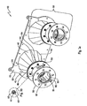
- FIG. 1a A perspective view of the 2-discharge cone embodiment of the invention device is shown in Fig. 1a .
- 2-discharge cone device 10 comprises a flow restrictor plate 20 and two discharge assemblies 30.
- Each discharge assembly 30 comprises a discharge cone 40; a circumferentially-apertured flange 44; an interior flange 47 (hidden, see Fig. 2 ); an extension tube 50; a circumferentially-apertured flange 52; a circumferentially-apertured flange 54; an exterior flange 57; 8 hexagonal internally screw-threaded nuts 60; 16 washers 61; and 8 hexagonal externally screw-threaded bolts 62.
- Flow restrictor plate 20 defines two larger attachment apertures 22; a plurality of evenly spaced-apart smaller attachment apertures 24; and two discharge apertures (not shown).
- the attachment apertures 22 are adapted for receiving a fastener or a device for lifting, suspending, or carrying flow restrictor plate 20 or 2-discharge cone device 10. Examples of such a device are chains, hooks (e.g., crane hooks), and wires.
- the attachment apertures 24 are adapted for receiving a fastener (e.g., externally screw-threaded bolt) in such a way that the 2-discharge cone device 10 can be sealably and firmly attached to a complimentarily configured receiving portion of a mixer (see Example 2).
- Diameter of one of the discharge apertures (not shown) of flow restrictor plate 20 is indicated between points 41 and 43.
- Each discharge cone 40 comprises a funnel portion 42 and connecting tube 45 (hidden, see Fig. 2 ).
- Funnel portion 42 defines an upstream aperture (not shown) between points 41 and 43.
- Connecting tube 45 (hidden, see Fig. 2 ) defines a downstream aperture (not indicated) of funnel portion 42.
- Diameter of the downstream aperture (not shown) of funnel portion 42 of discharge cone 40 is not indicated and is described later in this paragraph.
- Diameter of the upstream aperture (not shown) of funnel portion 42 is indicated between points 41 and 43 and is equal to diameter of discharge aperture (not shown) of flow restrictor plate 20.
- Circumferentially-apertured flange 52 defines downstream aperture 55 and circumferentially-apertured flange 54 defines an upstream aperture (not shown) that is the same size as downstream aperture 55. Diameter of downstream aperture 55 is indicated between points 51 and 53 of circumferentially-apertured flange 52. Diameter of downstream aperture 55 and the upstream aperture (not shown) in circumferentially-apertured flange 54 is equal to the diameter of the downstream aperture (not shown) of funnel portion 42 and preferably is about 80 mm.
- the diameter of the upstream aperture (not indicated) of funnel portion 42 is less than 4 times the diameter of downstream aperture (not shown) of circumferentially-apertured flange 44, and, thus, is less than 4 times diameter of downstream aperture 55 of circumferentially-apertured flange 52.
- the diameter of the upstream aperture (not indicated) of funnel portion 42 is less than 320 mm.
- Fig. 1b shows a magnified view of a hexagonal internally screw-threaded nut 60; washer 61; and an end of hexagonal externally screw-threaded bolt 62.
- Fig. 2 shows the exploded view of the 2-discharge cone 10 comprising the flow restrictor plate 20 and two discharge assemblies 30.
- Connecting tube 45 of discharge cone 40 is sealably connected to circumferentially-apertured flange 44.
- Each extension tube 50 is sealably connected to one of circumferentially-apertured flanges 52 and 54.
- Circumferentially-apertured flange 54 is sealably connected to circumferentially-apertured flange 44 of discharge cone 40 via interior flange 47 and fastener assemblies comprising hexagonal internally screw-threaded nuts 60; 16 washers 61; and 8 hexagonal externally screw-threaded bolts 62.
- a gasket (not shown) can be interposed between circumferentially-apertured flanges 44 and 54 and interior flange 47 so as to further seal their interconnection.
- twin screw mixer/conveyor apparatus 100 comprises the 2-discharge cone device 10 of Example 1 in sealed operative connection to a complimentarily configured receiving portion of the heatable mixing/conveying portion 110 of the aforementioned Spirator DU-trough conveyor screws mixer from Segler-Förderanlagen Maschinenfabrik GmbH.
- the heatable mixing/conveying portion 110 comprises a mixing/conveying conduit 111 (the second container) and a mixing/conveying means (not indicated).
- the mixing/conveying means comprises two rotatable shafts 112, two spiral wound tubings 113, and a plurality of connecting members (not shown).
- the mixing/conveying means (not indicated) is disposed in the mixing/conveying conduit 111.
- Each rotatable shaft 112 is disposed along a longitudinal axis 118 inside of, and spaced apart from, a different one of the spiral wound tubings 113.
- Each spiral wound tubing 113 is fixably connected (welded) to a different one of the rotatable shafts 112 via some of the number (preferably approximately equal number or one half) of the plurality of connecting members (not shown), which are spaced sequentially around rotatable shaft 112 at about 90 degree angles from nearest neighboring (as viewed along the ad rem spiral wound tubing 113) connecting members (not shown).
- Enough of the Spirator DU-trough conveyor screws mixer is shown in Fig. 3 to illustrate where the 2-discharge cone device 10 connects thereto.
- a hopper (not shown) containing RPET flakes (lengths of from 2 mm to 15 mm; prepared by grinding and removing any contaminants from post-consumer RPET) and connect a preparation vessel containing a known, quantity of a paste containing TPA, IPA, DEG, polycondensation catalyst, and MEG to separate inlets of the heatable mixing/conveying portion 110.
- Preparing ethylene terephthalate oligomers Modify the equipment used in Example 3 by replacing the storage vessel with an esterification reactor fitted internally with heating coils and a stir shaft/impeller operatively connected to a stir motor. Sealably connect ring adaptor 52 of 2-discharge cone device 10 of twin screw mixer/conveyor apparatus 100 to a complimentary fitting inlet of the esterification reactor (not shown). The operative connections establish fluid communication. Also connect a separate outlet of the paste preparation vessel to another inlet of the esterification reactor. Fit inlets of the esterification reactor with a cooling condenser so that any MEG vapor attempting to back out the inlets thereof will be condensed and returned into the esterification reactor.
- Prepolymer is prepared in the esterification reactor. Stir the contents in the esterification reactor and continuously discharge from the esterification reactor the prepared prepolymer from the esterification reactor at a discharge flow rate such that the added ingredients reside in the first esterification reactor on average for about 60 minutes.
- the prepared prepolymer discharged from the esterification reactor is useful for preparing crystalline, food-grade PET by known esterification/polycondensation processes such as the one described previously herein.
- the invention method is useful for exposing RPET to substantially full transesterifying effect of MEG even before the RPET is melted and does not require altering esterification reaction conditions.
- the invention method is useful for mixing ingredients comprising the solid thermoplastic particulates (e.g., RPET flakes) and the viscous material (e.g., a paste comprising TPA and MEG, or TPA, IPA, DEG, polycondensation catalyst, and MEG) in the first container (e.g., an esterification reactor) in a reduced period of time compared to period of time for melting one or both of the ingredients and mixing them together.
- the invention device and apparatus are useful for discharging the predispersion from the second container without clogging the device, even in presence of hot MEG vapor, and are useful in the invention method.
Landscapes
- Chemical & Material Sciences (AREA)
- Chemical Kinetics & Catalysis (AREA)
- Dispersion Chemistry (AREA)
- Mechanical Engineering (AREA)
- Medicinal Chemistry (AREA)
- Polymers & Plastics (AREA)
- Organic Chemistry (AREA)
- Engineering & Computer Science (AREA)
- Health & Medical Sciences (AREA)
- General Chemical & Material Sciences (AREA)
- Processes Of Treating Macromolecular Substances (AREA)
- Polyesters Or Polycarbonates (AREA)
- Processing And Handling Of Plastics And Other Materials For Molding In General (AREA)
- Accessories For Mixers (AREA)
- Mixers Of The Rotary Stirring Type (AREA)
- Separation, Recovery Or Treatment Of Waste Materials Containing Plastics (AREA)
Description
- The invention generally relates to a method of substantially homogeneously mixing ingredients comprising solid particulates and a viscous material in a container.
- Poly(ethylene terephthalate) (PET or polyethylene terephthalate) has many uses such as, for example, for making synthetic fibers and food-grade containers (e.g., beverage bottles). United States Patent Number
US 7,297,721 B2 ; PCT International Patent Application Publication NumberWO 98/41375 A JP H10-101784 A US 7,297,721 B2 , the process adds a paste of TPA, isophthalic acid (IPA), and MEG to an esterification reactor, stops the addiction, adds flakes of RPET, and then resumes adding additional paste. The RPET melts in the esterification reactor before fully mixing with the paste. InWO 98/41375 A JP H10-101784 A JP H10-101784 A US 2005/187306 andDE 10 2006 015 541 . - As is generally known and known from the above-referenced patent documents, RPET gradually decomposes when it is near or above its melting temperature (e.g., RPET flakes melt at about 245 degrees Celsius). If left unchecked, melted RPET will decompose to an extent that it would become unsuitable for preparing food-grade PET.
- There is a need in the art for an improved method of manufacturing PET using RPET.
- The inventors have recognized that the prior art requirement of first melting RPET solids before the RPET can form homogeneous mixtures with PET monomers is a deficiency of the prior art processes in view of the thermal decomposition liability of RPET. Accordingly, the inventors sought to reduce the period of time RPET spends in a melt phase but not also in homogeneous admixture with MEG during manufacturing of PET. At the esterification stage of PET manufacturing in particular, the inventors sought to reduce how long RPET would be exposed to decomposition conditions without also being intimately exposed to the full transesterifying affect of MEG. They desired a flexible solution in order to achieve this advantage without altering their esterification reaction conditions, since these had been optimized for production of food-grade PET. For example, the inventors desired to maintain the same reaction temperature and avoid using any solvent in their esterification reactor.
- The inventors describe herein a solution to the problem of mixing ingredients comprising RPET flakes and a paste comprising TPA and MEG in an esterification reactor in a reduced period of time compared to period of time for melting one or both of the ingredients and mixing them together. The inventors' solution comprises feeding a modified phase of RPET flakes into the esterification reactor. The modified phase of RPET flakes comprises a substantially homogeneous predispersion comprising the RPET flakes and a major portion of the paste. The solution also comprises separately feeding the remaining portion (i.e., minor portion) of the paste into the esterification reactor. The predispersion and remaining portion feeds enter the esterification reactor via a same inlet or different inlets thereof. The paste comprises an excess quantity of MEG (or, e.g., MEG and diethylene glycol (DEG)) capable of rapidly transesterifying substantially all of the RPET, preferably so as to produce ethylene terephthalate oligomers and proportionately reduce or prevent thermal decomposition of the RPET. The remaining quantity of MEG (or MEG and DEG) in the minor portion of the paste can be fed directly into the esterification reactor without depriving the RPET of a full transesterifying affect of MEG (or MEG and DEG). The substantially homogeneous predispersion of RPET flakes provides the RPET with exposure to substantially full transesterifying effect of MEG even before the RPET is melted and does not require altering of their esterification reaction conditions. Preferably, the paste and modified phase of RPET flakes further comprise isophthalic acid (IPA), a polycondensation catalyst, and diethylene glycol (DEG). The polycondensation catalyst means a substance effective for catalyzing an esterification reaction, transesterification reaction, or preferably esterification and transesterification reactions. In some embodiments the solution also advantageously produces a homogeneous mixture of RPET and ethylene terephthalate oligomers (described later) in the esterification reactor in significantly less time, with significantly less decomposition of the RPET, or both compared to period of time for melting the RPET flakes and fully mixing them and the PET monomers together in the esterification reactor. Advantageously, the inventors solution can be used in continuous feed and batch fed processes. Further, the inventors discovered that their solution can be applied to the mixing of any solid thermoplastic particulates, not just RPET flakes, with any viscous material containing the sufficient excess quantify of a reactant for the solid thermoplastic particulate as described later, not just the paste comprising MEG. The invention is especially valuable for, and in some embodiments, comprises, mixing the reactant(s) with solid thermoplastic particulates that contain a thermoplastic material that is prone to thermal decomposition (under the circumstances), wherein the mixing is done in such a way that the reactant can react with the thermoplastic material and reduce the thermal decomposition thereof. Preferably, the solid thermoplastic particulates are aromatic polyester resin particulates, and more preferably PET resins.
- In pursuing the aforementioned solution, the inventors discovered a problem when they tried to continuously feed a homogeneous paste comprising RPET flakes, TPA, and MEG, and preferably further comprising the IPA, polycondensation catalyst, and DEG, from a Segler double shaft screw blender containing a single cone-shaped discharge portion containing two outlets. The paste clogged the outlets of the Segler double shaft screw blender. Further, when the paste was being fed into an esterification reactor containing hot MEG vapor (e.g., > 200 °C at an ovexpressure of from 0.5 bar (50 kilopascals (kPa) to 1 bar (100 kPa) above ambient pressure) in its headspace, the inventors discovered that hot MEG vapor promptly initiated decomposing of the paste and caused bridging with unmelted RPET flakes, resulting in agglomerated RPET flakes clogging paste feed lines. The inventors solution generally comprises replacing the single cone-shaped discharge portion of the Segler double shaft screw blender with a plurality of smaller sized discharge cones as described later so as to enable clog-free operation of the resulting modified apparatus under the circumstance. Further, the inventors discovered that the modification can be applied to any container in need of a discharge portion, especially one in need of a clog-free discharge portion.
- The present invention provides a method of mixing ingredients comprising solid thermoplastic particulates and a viscous material in a first container without first melting the solid thermoplastic particulates, the method comprising feeding a predispersion comprising a substantially homogeneous mixture of the solid thermoplastic particulates and a major portion of the viscous material and feeding the remaining minor portion of the viscous material into the first container to give added ingredients in the first container; and mixing the added ingredients in the first container, wherein the solid thermoplastic particulates comprises a thermoplastic material and the major portion of the viscous material comprises a sufficient excess quantity of a reactant for the thermoplastic material. Still more preferably, the solid thermoplastic particulates are MET particulates. Preferably, the RPET particulates are RPET pellets or, more preferably, RPET flakes.
- The method of the present invention may employ a device for discharging a material from a second container without the material clogging the device, the device comprising a plurality of discharge cons; wherein each discharge cone has spaced-apart upstream and downstream apertures in fluid communication with each other, diameter of the upstream aperture being at most 4 times larger than diameter of the downstream aperture; wherein each discharge cone independently defines a volumetric space between the upstream and downstream apertures that is dimensioned and configured for containing a non-clogging amount of the material; and wherein each discharge cone independently is adapted for receiving the non-clogging amount of the material into the volumetric space through the upstream aperture and discharging the non-clogging amount of the material out of the volumetric space through the downstream aperture without clogging the device. Preferably, the device further comprises the second container and is in operative connection to the second container in such a way that a material contained in the second container can be discharged therefrom via the device without clogging the device.
- The method of the present invention may also employ an apparatus for mixing a material, wherein the apparatus comprises the device as in the second embodiment and a mixing portion (e.g., twin screw conveyor/mixer) comprising a second container; wherein the second container has a downstream outlet defining an opening and is sealably connected to the device around and proximal to the upstream apertures of the device in such a way that the device restricts the opening of the downstream outlet of the second container to the openings of the upstream apertures of the device; and the apparatus functions in such a way that when the second container of the apparatus contains a material, the material can be discharged from the apparatus via the device without clogging the device.
- The invention method is useful for preparing the predispersion and adding it into the first container (e.g., an esterification reactor) and thereby exposing RPET to substantially full transesterifying effect of MEG even before the RPET is melted. The invention method can be adapted to current manufacturing processes and does not require altering their esterification reaction conditions. The invention method reduces period of time RPET spends in a melt phase at high temperature (e.g., > 200 °C) but not also in admixture with MEG during manufacturing of PET. In some embodiments the iinvention method reduces how long RPET would be exposed to decomposition conditions without also being exposed to the transesterifying affect of MEG. In some embodiments the invention method is also useful for producing a homogeneous mixture of ingredients comprising the solid thermoplastic particulates (e.g., RPET flakes) and the viscous material (e.g., a paste comprising TPA, MEG, IPA, DEG, and a polycondensation catalyst) in the first container (e.g., an esterification reactor) in a reduced period of time compared to period of time for melting the solid thermoplastic particulates and fully mixing them with the viscous material in the first container (e.g., esterification reactor). Advantageously, the invention method can be used in continuous feed and batch fed processes. The invention method can be employed in, for example, a process for preparing quality-grade PET (e.g., food-grade PET) that employs RPET and PET monomers. The invention method is useful in other processes for reacting ingredients of the predispersion and viscous mixture together.
- The device and apparatus are employed in the method of the invention useful for discharging the material from the device or apparatus without clogging same, even when the first container has hot MEG vapor in its headspace. Thus, the invention device and apparatus are employed in the method of the invention useful in any discharging operation and are especially useful in manufacturing discharge operations, including quality-grade PET manufacturing discharge operations.
- As used herein, the term "clogging" means blocking at least 33 area percent of an outlet or blocking at least 33 percent of maximum flow from the outlet under the circumstances,. In some embodiments clogging means blocking at least 50 area percent, in some embodiments at least 70 area percent, and in some embodiments at least 95 area percent of the outlet. In some embodiments clogging means blocking at least 50 percent of maximum flow from, in some embodiments at least 70 percent of maximum flow from, and in some embodiments at least 95 percent of maximum flow from the outlet under the circumstances.
- The term "homogeneous" means uniformly mixed. The term "ingredient" means a substance added to, or to be added to, the first or second container.
- The term "IPA" means isophthalic acid, which has the following structural formula:

- The term "major portion" means greater than 50 percent. The term "minor portion" means less than 50 percent. Preferably, the major and minor portions together equal 100 percent (that is, there is no portion lost to scrap or leakage).
- The term "MEG" means monoethylene glycol, which has the following empirical formula: HOCH2CH2OH.
- The term "melting" means healing until liquefied.
- The term "mixing" means an act comprising blending.
- the term "PET" means poly(ethylene terephthalate).
- The term "RPET" means recycled poly(ethylene terephthalate).
- The term "solid thermoplastic particulates" means a finely divided substance that is not a liquid, gas, or plasma and has a melting point of from -20 °C to 500 °C, Preferably 20 °C to 300 °C. The finely divided substance can be amorphons or crystalline. In some embodiments, the finely divided substance has a maximum length (or diameter) of 20 millimeters (mm) and a minimum length (or diameter) of 0.5 mm. The finely divided substance can also contain immaterial amounts (e.g., less than 5 weight percent) of a residual liquid (e.g., MEG, DEG, or water) or gas (e.g., surface-adsorbed molecules of oxygen gas).
- The term "substantially" means at least 90%, preferably at least 95%, and more preferably at least 98%.
- The term "TPA" means terephthalic acid, which has the following structural formula:

- The term "viscous material" means a substance having a dynamic viscosity of from 200 centipoise (cP) to 200,000 cP at 20 degrees Celsius (°C), wherein the dynamic viscosity is measured according to the method described later.
- Additional embodiments are described in accompanying drawing(s) and the remainder of the specification, including the claims.
- Some embodiments of the present invention are described herein in relation to the accompanying drawing(s), which will at least assist in illustrating various features of the embodiments.
- Figure (
Fig.) 1a shows a perspective view of an embodiment of the device of Example 1. -
Fig. 1b shows a magnified view of a detail inFig. 1a . -
Fig. 2 shows an exploded view of the embodiment of the device of Example 1. -
Fig. 3 shows a top down, partial view of an embodiment of the apparatus of Example 2. - The invention relates to the method of substantially homogeneously mixing ingredients comprising solid thermoplastic particulates and a viscous material in a first container, to a non-clogging device, as summarized previously.
- The word "optionally" means "with or without." For example, "optionally, an additive" means with or without an additive.
- In an event where there is a conflict between a compound name and its structure, the structure controls.
- In an event where there is a conflict between a unit value that is recited without parentheses, e.g., 2 inches, and a corresponding unit value that is parenthetically recited, e.g., (5 centimeters), the unit value recited without parentheses controls.
- As used herein, "a," "an," and "the," are used following an open-ended term such as comprising to mean "at least one." In any aspect or embodiment of the instant invention described herein, the open-ended terms "comprising," "comprises," and the like (which are synonymous with "including," "having," and "characterized by") may be replaced by the respective partially closed phrases "consisting essentially of," "consists essentially of," and the like or the respective closed phrases "consisting of," "consists of," and the like to give another aspect or embodiment of the instant invention. The partially closed phrases such as "consisting essentially of" and the like limits scope of a claim to materials or steps recited therein and those that do not materially affect the basic and novel characteristic(s) of the claimed invention. The term "characterizable" is open-ended and means distinguishable.
- In the present application, when referring to a preceding list of elements (e.g., ingredients), the phrases "mixture thereof," "combination thereof," and the like mean any two or more, including all, of the listed elements. The term "or" used in a listing of members, unless stated otherwise, refers to the listed members individually as well as in any combination, and supports additional embodiments reciting any one of the individual members (e.g., in an embodiment reciting the phrase "10 percent or more," the "or" supports another embodiment reciting "10 percent" and still another embodiment reciting "more than 10 percent."). The term "plurality" means two or more, wherein each plurality is independently selected unless indicated otherwise. The term "independently" means separately without regard for another. The terms "first," "second," et cetera serve as a convenient means of distinguishing between two or more elements or limitations (e.g., a first chair and a second chair) and do not imply quantity or order unless specifically so indicated. The symbols "≤" and "≥" respectively mean less than or equal to and greater than or equal to. The symbols "<" and ">" respectively mean less than and greater than. The term "characterizable" means capable of being distinguished, if desired.
- Any headings herein are used only for convenience of the reader and do not limit, and should not be interpreted as limiting, the present invention.
- Where the invention, or any portion thereof (e.g., element or step), is defined in the alternative by a Markush group having two or more members, the invention contemplates preferred embodiments too numerous to recite each one herein. For convenience, such preferred embodiments can be readily determined by: (i) selecting any single member from the Markush group, thereby limiting scope of the Markush group to the selected single member thereof; or (ii) deleting any single member from the Markush group, thereby limiting the Markush group to any one of the remaining member(s) thereof. In some embodiments the member that is selected or deleted is based on one of the Examples or other species of the present invention described herein.
- This specification may refer to certain well-known testing standards promulgated by certain organizations, which are referred to herein by their acronyms. The acronym "ANSI" stands for American National Standards Institute, the name of an organization headquartered in Washington, D.C., USA. The acronym "ASTM" stands for ASTM International, the name of an organization headquartered in West Conshohocken, Pennsylvania, USA; ASTM International was previously known as the American Society for Testing and Materials. The acronym "DIN" stands for Deutsches Institut für Normung e. V., the name of an organization headquartered in Berlin, Germany. The acronym "ISO" stands for International Organization for Standardization, the name of an organization headquartered in
Geneva 20, Switzerland. - Part of the invention method comprises the aforementioned feeding steps. The steps of feeding the predispersion and remaining portion of the viscous can be batch feeding steps, continuous feeding steps or a combination thereof. In some embodiments the feeding steps respectively consist essentially of feeding a batch of the predispersion and a batch of the remaining portion of the viscous material into the first container (e.g., esterification reactor). In some embodiments the feeding steps respectively comprise continuously feeding the predispersion and the remaining portion of the viscous material into the first container; and the method further comprises intermittently or continuously removing a reaction product thereof from the first container. The rate of removal (e.g., weight per hour) of the reaction product from the first container can be adjusted so as to allow the added ingredients to reside in the first container for an average amount of time (e.g., an average of about 1 hour).
- Feeding of the predispersion and the remaining portion of the viscous material into the first container (e.g., esterification reactor) can be done by any means. Preferably the feeds are metered (e.g., with a full bore coriolis-type flow meter) so as to measure and control amounts and relative amounts thereof being added into the first container. Preferably, the first container has separate inlets and the feeds of the predispersion and the minor portion of the viscous material are separate and fed via a different one of the separate inlets into the first container. When the solid thermoplastic particulates comprises RPET particulates (e.g., RPET flakes or pellets) and the viscous material comprises TPA/MEG or TPA/IPA/MEG/DEG/polycondensation catalyst, preferably, the feed of the RPET/TPA/MEG predispersion or predispersion of RPET/TPA/IPA/MEG/DEG/polycondensation catalyst, as the case may be, is at a predispersion temperature of from 0 °C to 80 °C, and more preferably from 45 °C to 75 °C, and still more preferably from 50 °C to 65 °C. Also preferably, the RPET comprises from greater than 0 weight percent (wt%) to a maximum wt% that is operable in the invention method, wherein wt% is based on the total weight of RPET plus viscous material. In some embodiments the maximum wt% that is operable in the invention method is 25 wt% of the total weight of RPET plus viscous material. In some embodiments, the RPET comprises from greater than 0 wt% to 9.9 wt% of the total weight of RPET plus viscous material.
- The ingredients of the feeds or ingredients thereof can be stored until such time as the feeds are prepared. Prior to entering the first container, each feed can also be stored. Storage of the ingredients is not important. Preferably each feed is not stored but promptly added into the first container. Ingredients and feeds can be stored in any suitable storage vessel. Examples of suitable storage vessels are a particulates silo, liquid storage tank, and preparation vessel. An example of the preparation vessel is a stirred tank. For example in the preparation of PET using the invention method, measured amounts of TPA and MEG and any additional PET monomers (e.g., IPA and DEG) and additional reaction ingredients (e.g., catalyst, additive, or a combination thereof) are premixed in the preparation vessel in such a way so as to prepare the viscous material. The solid thermoplastic particulates can be stored in a silo until such time as mixing with the major portion of the viscous material.
- Preferably, the predispersion and remaining portion of the paste lack a solvent other than MEG, some of which can function as a solvent. In some embodiments the predispersion comprises RPET particulates, TPA, MEG, IPA, DEG, and polycondensation catalyst. In such embodiments density of the predispersion preferably is less than 1,400 kilograms per cubic meter (kg/m3). When RPET flakes are employed, preferably bulk density of the RPET flakes is from about 300 kg/m3 to about 450 kg/m3.
- In some embodiments the viscous material comprises a paste, slurry, or liquid. In some embodiments the viscous material comprises the slurry or paste. In some embodiments the viscous material comprises the paste. Preferably, the viscous material comprises a substantially homogeneous mixture. When TPA and MEG or TPA, IPA, DEG, polycondensation catalyst, and MEG are employed, preferably the viscous material comprises a substantially homogeneous mixture comprising the TPA and MEG or of TPA, IPA, DEG, polycondensation catalyst, and MEG. In some embodiments the major portion of the viscous material is greater than 50% or greater and the minor portion of the viscous material is less than 50% or lesser. More preferably the major portion of the viscous material is from 60% to 80% and the minor portion of the viscous material is from 40% to 20%, respectively.
- The solid thermoplastic particulates can be any shape. Preferably, the solid thermoplastic particulates have a uniform shape or an irregular shape. Examples of solid thermoplastic particulates having the uniform shape are pellets and granules. Examples of solid thermoplastic particulates having the irregular shape are flakes. In some embodiments solid thermoplastic particulates are the RPET particulates and the RPET particulates comprise RPET pellets or, preferably, RPET flakes. Preferably the solid thermoplastic particulates have a melting temperature that is less than 300 °C and greater than ambient temperature (e.g., greater than 40 °C). The solid thermoplastic particulates can have any practical size. Preferably, at least 90% of the solid thermoplastic particulates have a maximum length of 12 mm and a minimum length of 2 mm. In some embodiments at least 95% of the solid thermoplastic particulates have a maximum length of 10 mm. More preferably, at least 95% of the solid thermoplastic particulates have a length of from about 2 mm to about 10 mm.
- The predispersion or viscous material can contain very minor amounts (< 10 wt% based on total weight of the predispersion or viscous material) of other ingredients such as, for example, a polycondensation catalyst or an additive. Examples of suitable catalysts are antimony trioxide, germanium dioxide, titanium alcoholates (e.g., titanium (C1-C5)alcoholates), or a combination thereof. Examples of suitable additives are a colorant, heat stabilizer, and optical brightener. Preferably, the other ingredients are characterized as being food-grade.
- Another step of the invention method comprises the aforementioned mixing the added ingredients step. The mixing or blending of the added ingredients in the first container (e.g., esterification reactor) can be performed by any suitable means (e.g., agitating, shaking, stirring, or a combination thereof) so as to produce a substantially homogeneous mixture.
- The first container (e.g., esterification reactor) is adapted for the mixing of the added ingredients, and preferably for controlling temperature thereof. For example, the first container can contain guide plates and an impeller, wherein the impeller is in sequential operative connection and rotating communication with a stir shaft and stirrer motor. Alternatively, the mixing could agitate contents of the first container with a gas (e.g., air or nitrogen gas) purge or shaking the first container. Preferably, the first container contains internal heating coils so as to heat contents of the first container to a suitable temperature (e.g., from 250 °C to 280 °C for transesterification of RPET and esterification of TPA/MEG or TPA/IPA/MEG/DEG/polycondensation catalyst). Also, preferably the first container is adapted for preventing loss of vapor from headspace therein back out an inlet thereof. In some embodiments at least the predispersion feed inlet, and more preferably the predispersion feed inlet and the viscous material feed inlet of the first container is in operative connection and fluid communication with a condenser(s) for condensing any vapor (e.g., hot MEG vapor) attempting to leave the first container via the feed inlet. Preferably, the first container is an esterification reactor such as a reactor suitable for preparing the ethylene terephthalate oligomers.
- The invention method is flexible and in some embodiments contemplates additional steps. For example, in some embodiments the invention method further comprises a further step or steps before the feeding step. In some embodiments, the further step comprises mixing the solid thermoplastic particulates and the major portion of the viscous material to give the predispersion. In preparing the predispersion, for example, measured amounts of the solid thermoplastic particulates and major portion of the viscous material can be metered into a mixer (e.g., a twin screw conveyor/mixer) comprising the second container, heated if desired, but not melted, (e.g., heated to 50 degrees Celsius (°C) when using RPET, which melts at about 245 °C), and mixed so as to prepare the predispersion. The mixing or blending of ingredients to produce a feed can be performed by any suitable means (e.g., agitating, shaking, stirring, or a combination thereof). In some embodiments the mixing produces a substantially homogeneous mixture, and more preferably a homogeneous mixture. Preferably, the predispersion preferably is fed directly (e.g., via a direct connection or via an intermediary pipe) from the mixer into the first container (e.g., esterification reactor). For practical reasons, it is preferably to initiate operation of the mixer used to prepare the dispersion with the viscous material only, heating the viscous material therein, if desired, to a temperature well below melting point of the solid thermoplastic particulates, and then gradually meter into the mixer increasing amounts of the solid thermoplastic particulates until a desired concentration of solid thermoplastic particulates in the predispersion exiting the mixer is achieved. Thereafter, mixing can be continued in a continuous flow operation or be temporarily stopped if desired. Preferably, the viscous material is prepared ahead of time in a single preparation vessel, which is in operative connection and fluid communication via separate conduits to both the mixer and the first container such that the composition of the major portion of the viscous material (used to prepare the predispersion in the mixer) and the composition of the minor portion of the viscous material (added directly to the first container) are the same. Preferably, the weight of the viscous material directly entering the first container from the preparation vessel is less than the weight of the viscous material leaving the preparation vessel by the weight of the viscous material added into the mixer. That is, preferably there is no leakage or scrap of the viscous material. Powering transfers of such ingredients from their storage locations to their preparation location or the first or second container, and from the first or second container to subsequent locations can be accomplished by any suitable powering means such as, for example, gravity, a pneumatic conveying system, pump (e.g., positive displacement pump), or a combination thereof.
- More preferably, the mixer comprising the second container comprises a screw conveyor/mixer (e.g., a horizontal twin screw conveyor/mixer), still more preferably the twin screw conveyor/mixer is a double shaft screw blender (e.g., Sirator DU-trough conveyor screws, available from Segler-Förderanlagen Maschinenfabrik GmbH, Berge, Germany). The Segler double shaft screw blender has two intermeshing screws having an aspect ratio (i.e., length-to-diameter ratio) of from 5 to 7. Typically, the intermeshing screws are self-cleaning and can be rotated at variable speeds (i.e., different revolutions per minute (rpm), e.g., from 20 rpm to 60 rpm). Preferably, the Segler double shaft screw blender is disposed at a slight downward pitch relative to horizontal plane. Even more preferably, the Segler double shaft screw blender is retrofitted with the invention device as described later, and thereby comprises an embodiment of the invention apparatus. Preferably when the ingredients used to prepare the predispersion comprise the RPET particulates and TPA/MEG, they dwell in the Segler double shaft screw blender for from 35 seconds to 50 seconds. Also, preferably only so much of the ingredients is added into the Segler double shaft screw blender so as to just cover the twin screws, i.e., enough to occupy from 60 percent (%) to 70% of the volumetric space therein. Preferably, the flow rate of predispersion leaving the Segler double shaft screw blender is from 0.4 meter per second (m/sec) to 0.6 m/sec when the outlet aperture thereof has a diameter of 80 mm. Also preferably, when RPET particulates in form of flakes are employed, the weight ratio of RPET flakes to viscous material (comprising TPA/MEG or TPA/MEG/IPA/DEG/polycondensation catalyst) is 1:9 or lower, and more preferably from about 1:7 to 1:8.
- In some embodiments the solid thermoplastic particulates can contain contaminants and an additional step or steps before the feeding step removes the contaminants from the solid thermoplastic particulates. For example, when the RPET is obtained from post-consumer PET, the RPET can contain contaminants that have been introduced during the collection and processing thereof. Examples of the contaminants sometimes found in post-consumer RPET are colored PET (excluding RPET in light blue to dark blue colors); other colored polymers (e.g., colored polyolefins or polyvinyl chloride polymers); black particles (e.g., from processing machinery); iron dust, aluminum nuggets, stones, wood, glass, and paper. In such embodiments, the additional steps comprise passing the contaminated RPET through at least one of strong magnets (e.g., for removal of magnetized particles such as the iron dust); a sieving machine (e.g., for removal of fines of up to 2 millimeters (mm) diameter, oversized particles having diameters greater than 10 mm to 15 mm, preferably 10 mm to 12 mm, or both); an optical sorting system (e.g., to remove colored plastics); or a combination of at least two thereof.
- In some embodiments the invention method further comprises a further step or steps after the feeding step. For example, when the invention method employs the solid thermoplastic particulates comprising RPET particles and the viscous material comprising a substantially homogeneous mixture comprising TPA and MEG or, preferably substantially homogeneous mixture comprising TPA, IPA, DEG, polycondensation catalyst, and MEG. In some embodiments the substantially homogeneous mixture comprises TPA, IPA, DEG, and MEG. In some embodiments the substantially homogeneous mixture further comprises at least one additive other than a monomer for preparing PET, at least one additional catalyst (e.g., the polycondensation catalyst or another catalyst), or a combination thereof. In some embodiments the invention method further comprises transesterifying the RPET and reacting (esterifying) the added ingredients TPA and MEG, or preferably with the added ingredients TPA, IPA, DEG, polycondensation catalyst, and MEG, at a temperature of from 250 °C to 270 °C in such a way so as to produce a mixture comprising PET and ethylene terephthalate oligomers in the first container. In some embodiments the viscous material further comprises isophthalic acid and at least one polycondensation catalyst; and the invention method further comprises transesterifying the RPET and reacting the added ingredients TPA, IPA, DEG, polycondensation catalyst, and MEG at a temperature of from 250 °C to 270 °C in such a way so as to produce the mixture comprising PET and ethylene terephthalate oligomers in the first container. The term "ethylene terephthalate oligomer" means a molecule comprising from 2 to 10, and in some embodiment 2 to 5, residuals of TPA, IPA, MEG, or DEG, wherein there is at least one residual of TPA or IPA and at least one residual of DEG or MEG, and any additional residuals independently are of TPA, IPA, MEG, or DEG. The ethylene terephthalate oligomers are useful for preparing PET via polycondensation thereof. The esterification reactions described in this paragraph can be done in the same or different containers.
- In some embodiments the invention method employs the first container as a first esterification reactor and further employs a second esterification reactor, which is in operative connection and fluid communication with the first esterification reactor. In some embodiments, the invention method further comprises polycondensing the ethylene terephthalate oligomers so as to produce PET or poly(ethylene terephthalate isophthalate). Preferably, the invention method employs three polycondensation reactors in series of first, second, and third polycondensation reactors. In some embodiments the invention method further employs a solid state polycondensation step downstream from the polycondensation step of the third polycondensation reactor. More preferably, the first and second esterification reactors and first, second and third polycondensation reactors are sequentially in operative connection to, and in at least periodic fluid communication with, each other. Still more preferably, the ingredients are kept in the first and second esterification reactors and first polycondensation reactor for an average residence time and are continuously flowed through the second and third polycondensation reactors. Preferably, pressure in each of the reactors is decreased in a stepwise fashion from one reactor to the next reactor in the series, starting at a pressure from slightly greater than ambient pressure to 0.5 bar (50 kilopascals (kPa, preferably 90 kPa to 50 kPa) in the first esterification reactor and ending with approximately 1 millibar (0.1 kPa) pressure in the third polycondensation reactor. Preferably, temperature of contents in the reactors is increased in a stepwise fashion going from one reactor to the next reactor in the series, starting at a temperature of from about 255 °C to about 265 °C in the first esterification reactor (i.e., the first container) and ending with a temperature of from about 265 °C to about 285 °C in the third polycondensation reactor.
- Turning to the employable in the method of the invention device, naturally each discharge cone independently has a proximal end defining the upstream aperture and a distal end defining the downstream aperture and each aperture can be characterized by a diameter or cross-sectiorial area. Each discharge cone of the device has an in terior surface that defines the volumetric space. Each interior surface of the discharge cone independently is configured in such a way so as to enable the clog-free operation. A preferred configuration of the interior surface of the discharge cone is of a smooth construction, more preferably polished smooth or coated with a non-stick coating such as, for example, a poly(tetrafluoroethylene). Preferably, the diameter of the upstream aperture is at most 3.5 times larger, and more preferably at most 3.0 times larger than diameter of the downstream aperture of the discharge cone.
- The diameter (or cross-sectional area) of the upstream aperture of, and the volumetric space in, each discharge cone is sized relative to the diameter of downstream aperture of the discharge cone so as to enable clog-free operation thereof under the circumstances. Examples of such circumstances are a particular predispersion composition (which can influence adhering property of the predispersion to the interior surface of the discharge cone); the particular viscosity and density of the predispersion; and the particular temperature and flow rate of the predispersion.
- The invention device can be constructed of any material suitable for its intended use (e.g., for use with a predispersion containing the solid thermoplastic particulates or melt thereof as the viscous material). Examples of preferred materials are polished aluminum alloy or stainless steel. In some embodiments the interior surface of the discharge cone comprises a non-stick coating such as, for example, a poly(tetrafluoroethylene) coating; or the discharge cone is constructed of a non-stick material such as, for example, poly(tetrafluoroethylene).
- Turning to the employed in the method of the invention apparatus, it is configured in such a way that the device would restrict flow of any material that is discharged from the mixing portion of the apparatus into the volumetric space in the device, wherein the restriction is such that the material would flow into the volumetric space in the device only via the upstream apertures of the device. Preferably, the mixing portion of the apparatus comprises the aforementioned Segler double shaft screw blender, except where the single discbarge cone and outlets of the Segler double shaft screw blender have been replaced with the device, and more preferably by a two discharge-cone device as described later in Example 1.
- Purchase RPET from a plastics recycler (e.g., Waste Management, Inc., Houston, Texas, USA). Purchase MEG, DEG, polycondensation catalyst, TPA, and IPA from Sigma-Aldrich Company, St. Louis, Missouri, USA.
- Measure dynamic viscosity at 20 °C using a Brookfield CAP-2000 cone and plate viscometer (Brookfield Engineering Laboratories, Inc., Middleboro, Massachusetts, USA) and the immediately following test method. Test method: If necessary, warm up the viscometer for about 30 minutes. Calibrate the viscometer using a viscosity standard by conventional means. Set the viscometer's temperature control, dispense a test sample onto the plate, and affix an appropriate cone (as would be known) thereto such that the affixed test sample completely covers a face of the cone and extends about 1 millimeter beyond the cone's edge. Wait about from 1 minute to 3 minutes to allow the affixed test sample to reach temperature equilibrium, then execute a viscosity measurement therewith with the cone being rotated at an appropriate rate for the cone (as would be known) and record the resulting outputted viscosity value for the test sample.
- Non-limiting examples of the present invention are described below that illustrate some specific embodiments and aforementioned advantages of the present invention. Preferred embodiments of the present invention incorporate one limitation, and more preferably any two, limitations of the Examples, which limitations thereby serve as a basis for amending claims.
- A 2-discharge cone device. A perspective view of the 2-discharge cone embodiment of the invention device is shown in
Fig. 1a . InFig. 1a , looking slightly downward, 2-discharge cone device 10 comprises a flowrestrictor plate 20 and twodischarge assemblies 30. Eachdischarge assembly 30 comprises adischarge cone 40; a circumferentially-apertured flange 44; an interior flange 47 (hidden, seeFig. 2 ); anextension tube 50; a circumferentially-apertured flange 52; a circumferentially-apertured flange 54; anexterior flange 57; 8 hexagonal internally screw-threadednuts 60; 16washers 61; and 8 hexagonal externally screw-threadedbolts 62.Extension tubes 50 are optional. Flowrestrictor plate 20 defines twolarger attachment apertures 22; a plurality of evenly spaced-apartsmaller attachment apertures 24; and two discharge apertures (not shown). The attachment apertures 22 are adapted for receiving a fastener or a device for lifting, suspending, or carryingflow restrictor plate 20 or 2-discharge cone device 10. Examples of such a device are chains, hooks (e.g., crane hooks), and wires. The attachment apertures 24 are adapted for receiving a fastener (e.g., externally screw-threaded bolt) in such a way that the 2-discharge cone device 10 can be sealably and firmly attached to a complimentarily configured receiving portion of a mixer (see Example 2). Diameter of one of the discharge apertures (not shown) offlow restrictor plate 20 is indicated betweenpoints discharge cone 40 comprises afunnel portion 42 and connecting tube 45 (hidden, seeFig. 2 ).Funnel portion 42 defines an upstream aperture (not shown) betweenpoints Fig. 2 ) defines a downstream aperture (not indicated) offunnel portion 42. Diameter of the downstream aperture (not shown) offunnel portion 42 ofdischarge cone 40 is not indicated and is described later in this paragraph. Diameter of the upstream aperture (not shown) offunnel portion 42 is indicated betweenpoints flow restrictor plate 20. Circumferentially-apertured flange 52 definesdownstream aperture 55 and circumferentially-apertured flange 54 defines an upstream aperture (not shown) that is the same size asdownstream aperture 55. Diameter ofdownstream aperture 55 is indicated betweenpoints apertured flange 52. Diameter ofdownstream aperture 55 and the upstream aperture (not shown) in circumferentially-apertured flange 54 is equal to the diameter of the downstream aperture (not shown) offunnel portion 42 and preferably is about 80 mm. The diameter of the upstream aperture (not indicated) offunnel portion 42, which is indicated betweenpoints apertured flange 44, and, thus, is less than 4 times diameter ofdownstream aperture 55 of circumferentially-apertured flange 52. Preferably, the diameter of the upstream aperture (not indicated) offunnel portion 42 is less than 320 mm. -
Fig. 1b shows a magnified view of a hexagonal internally screw-threadednut 60;washer 61; and an end of hexagonal externally screw-threadedbolt 62. -
Fig. 2 shows the exploded view of the 2-discharge cone 10 comprising theflow restrictor plate 20 and twodischarge assemblies 30. Connecting tube 45 ofdischarge cone 40 is sealably connected to circumferentially-apertured flange 44. Eachextension tube 50 is sealably connected to one of circumferentially-apertured flanges apertured flange 54 is sealably connected to circumferentially-apertured flange 44 ofdischarge cone 40 viainterior flange 47 and fastener assemblies comprising hexagonal internally screw-threadednuts 60; 16washers 61; and 8 hexagonal externally screw-threadedbolts 62. If desired, a gasket (not shown) can be interposed between circumferentially-apertured flanges interior flange 47 so as to further seal their interconnection. - Twin screw mixer/conveyor apparatus comprising the 2-discharge cone device. A top down, partial view of the twin screw mixer/conveyor apparatus comprising the 2-
discharge cone device 10 of Example 1 is shown inFig. 3 . InFig. 3 , twin screw mixer/conveyor apparatus 100 comprises the 2-discharge cone device 10 of Example 1 in sealed operative connection to a complimentarily configured receiving portion of the heatable mixing/conveyingportion 110 of the aforementioned Spirator DU-trough conveyor screws mixer from Segler-Förderanlagen Maschinenfabrik GmbH. The heatable mixing/conveyingportion 110 comprises a mixing/conveying conduit 111 (the second container) and a mixing/conveying means (not indicated). The mixing/conveying means (not indicated) comprises tworotatable shafts 112, two spiral wound tubings 113, and a plurality of connecting members (not shown). The mixing/conveying means (not indicated) is disposed in the mixing/conveyingconduit 111. Eachrotatable shaft 112 is disposed along alongitudinal axis 118 inside of, and spaced apart from, a different one of thespiral wound tubings 113. Each spiral woundtubing 113 is fixably connected (welded) to a different one of therotatable shafts 112 via some of the number (preferably approximately equal number or one half) of the plurality of connecting members (not shown), which are spaced sequentially aroundrotatable shaft 112 at about 90 degree angles from nearest neighboring (as viewed along the ad rem spiral wound tubing 113) connecting members (not shown). Enough of the Spirator DU-trough conveyor screws mixer is shown inFig. 3 to illustrate where the 2-discharge cone device 10 connects thereto. - Mixing RPET flakes and a paste comprising TPA, MEG, DEG, IPA, and antimony triacetate or antimony ethylene glycolate as a polycondensation catalyst using the twin screw mixer/conveyor apparatus to prepare a predispersion. Referring again to
Fig. 3 , direction of flow of the solid thermoplastic particulates and viscous material being mixed in heatable mixing/conveyingportion 110 of twin screw mixer/conveyor apparatus 100 of Example 2 to give the predispersion is indicated byarrow 120. The predispersion is then discharged through the downstream apertures 55 (seeFig. 1a ) of the 2-discharge cone device 10 portion of twin screw mixer/conveyor apparatus 100 as indicated byarrows portion 110. From the preparation vessel (not shown) containing the known quantity of a paste containing TPA, IPA, DEG, polycondensation catalyst, MEG, continuously feed a metered major portion (i.e., major amount) of the paste into heatable mixing/conveyingportion 110 of operating twin screw mixer/conveyor apparatus 100 via an upstream inlet (not shown in the partial view ofFig. 3 ) in heatable mixing/conveyingportion 110, which is set to heat the paste to 60 °C. When temperature of the paste reaches 60 °C and is flowing out the 2-discharge cone device 10 portion of twin screw mixer/conveyor apparatus 100 as indicated byarrows portion 110. Meter in the RPET flakes in a gradually increasing quantity to initially to give a predispersion containing 0.5 wt% RPET flakes, then 1 wt% RPET flakes, and ultimately a 9.0 wt% concentration of the RPET flakes. Homogeneously mix the RPET flakes and paste in heatable mixing/conveyingportion 110 in such a way so as to ultimately give a predispersion at 60 °C flowing at a discharge flow rate of 0.5 m/sec out of the 2-discharge cone device 10 portion of twin screw mixer/conveyor apparatus 100 as indicated byarrows portion 110 of twin screw mixer/conveyor apparatus 100. The predispersion is discharged from twin screw mixer/conveyor apparatus 100 without clogging. Collect the discharged predispersion in a storage vessel (not shown). - Preparing ethylene terephthalate oligomers. Modify the equipment used in Example 3 by replacing the storage vessel with an esterification reactor fitted internally with heating coils and a stir shaft/impeller operatively connected to a stir motor. Sealably
connect ring adaptor 52 of 2-discharge cone device 10 of twin screw mixer/conveyor apparatus 100 to a complimentary fitting inlet of the esterification reactor (not shown). The operative connections establish fluid communication. Also connect a separate outlet of the paste preparation vessel to another inlet of the esterification reactor. Fit inlets of the esterification reactor with a cooling condenser so that any MEG vapor attempting to back out the inlets thereof will be condensed and returned into the esterification reactor. Add a prepolymer heel comprising a quantity of ethylene terephthalate oligomers into the esterification reactor, and heat the prepolymer heel in the first esterification reactor to 255 °C to 265 °C with stirring. Then repeat the procedure of Example 3, and instead of collecting the predispersion in the storage vessel, feed the predispersion from the 2-discharge cone device 10 portion of twin screw mixer/conveyor apparatus 100 directly into the esterification reactor without clogging thedevice 10 or inlet of the reactor. Simultaneously feed the remaining minor portion (minor amount) of the paste directly from the preparation vessel into the esterification reactor via the other inlet therein without clogging the inlet of the reactor. Prepolymer is prepared in the esterification reactor. Stir the contents in the esterification reactor and continuously discharge from the esterification reactor the prepared prepolymer from the esterification reactor at a discharge flow rate such that the added ingredients reside in the first esterification reactor on average for about 60 minutes. The prepared prepolymer discharged from the esterification reactor is useful for preparing crystalline, food-grade PET by known esterification/polycondensation processes such as the one described previously herein. - As shown by the Examples, the invention method is useful for exposing RPET to substantially full transesterifying effect of MEG even before the RPET is melted and does not require altering esterification reaction conditions. The invention method is useful for mixing ingredients comprising the solid thermoplastic particulates (e.g., RPET flakes) and the viscous material (e.g., a paste comprising TPA and MEG, or TPA, IPA, DEG, polycondensation catalyst, and MEG) in the first container (e.g., an esterification reactor) in a reduced period of time compared to period of time for melting one or both of the ingredients and mixing them together. The invention device and apparatus are useful for discharging the predispersion from the second container without clogging the device, even in presence of hot MEG vapor, and are useful in the invention method.
Claims (12)
- A method of mixing ingredients comprising solid thermoplastic particulates and a viscous material in a first container without first melting the solid thermoplastic particulates, the method comprising feeding a predispersion comprising a substantially homogeneous mixture of the solid thermoplastic particulates and a major portion of the viscous material and feeding the remaining minor portion of the viscous material into a first container to give added ingredients in the first container; and mixing the added ingredients in the first container, wherein the solid thermoplastic particulates comprises a thermoplastic material and the major portion of the viscous material comprises a sufficient excess quantity of a reactant for the thermoplastic material.
- The method as in claim 1, the method further comprising a step before the feeding step, the further step comprising mixing the solid thermoplastic particulates and the major portion of the viscous material to give the predispersion.
- The method as in any one of the preceding claims, wherein the feeding steps respectively consist essentially of feeding a batch of the predispersion and a batch of the remaining portion of the viscous material into the first container.
- The method as in claim 1 or 2, wherein the feeding steps respectively comprise continuously feeding the predispersion and the remaining portion of the viscous material into the first container; and the method further comprises intermittently or continuously removing a reaction product thereof from the first container.
- The method as in any one of the preceding claims, wherein the solid thermoplastic particulates comprise irregularly-shaped particles and the irregularly-shaped particles are flakes of recycled poly(ethylene terephthalate)
- The method as in any one of the preceding claims, wherein the viscous material has a dynamic viscosity of 200 centipoise or greater.
- The method as in claim 6, wherein the viscous material comprises a substantially homogeneous mixture comprising terephthalic acid and monoethylene glycol.
- The method as in claim 7, wherein the viscous material further comprises isophthalic acid and at least one of a polycondensation catalyst and diethylene glycol.
- The method as in any one of the preceding claims, wherein the solid thermoplastic particulates comprise recycled poly(ethylene terephthalate) particles; the viscous material comprises a substantially homogeneous mixture comprising terephthalic acid and monoethylene glycol; the feed of the predispersion is at a temperature of from 0 degrees Celsius to 70 degrees Celsius; and the recycled poly(ethylene terephthalate) comprises from greater than 0 weight percent to 50 weight percent of the total weight of the recycled poly(ethylene terephthalate) particles plus viscous material.
- The method as in claim 9, the method further comprises transesterifying the recycled poly(ethylene terephthalate) and reacting the added ingredients terephthalic acid and monoethylene glycol at a temperature of from 250 degrees Celsius to 270 degrees Celsius in such a way so as to produce ethylene terephthalate oligomers in the first container.
- The method as in any one of the preceding claims, the method employing a device to feed the predispersion into the first container, wherein the device is effective for discharging a material from a second container into the first container without the material clogging the device, the device comprising a plurality of discharge cones; wherein each discharge cone has spaced-apart upstream and downstream apertures in fluid communication with each other, diameter of the upstream aperture being at most 4 times larger than diameter of the downstream aperture; wherein each discharge cone independently defines a volumetric space between the upstream and downstream apertures that is dimensioned and configured for containing a non-clogging amount of the material; and wherein each discharge cone independently is adapted for receiving the non-clogging amount of the material into the volumetric space through the upstream aperture and discharging the non-clogging amount of the material out of the volumetric space through the downstream aperture without clogging the device.
- The method as in claim 11, the method employing an apparatus to prepare the predispersion and feed the predispersion into the first container, wherein the apparatus is effective for mixing a material and wherein the apparatus comprises the device and a mixing portion comprising a second container; wherein the second container has a downstream outlet defining an opening and is sealably connected to the device around and proximal to the upstream apertures of the device in such a way that the device restricts the opening of the downstream outlet of the second container to the openings of the upstream apertures of the device; and the apparatus functions in such a way that when the second container of the apparatus contains a material, the material can be discharged from the apparatus via the device without clogging the device.
Priority Applications (5)
| Application Number | Priority Date | Filing Date | Title |
|---|---|---|---|
| EP20140176212 EP2789382A1 (en) | 2010-09-30 | 2011-08-31 | Mixing device. |
| PL11751555T PL2621619T3 (en) | 2010-09-30 | 2011-08-31 | Method of mixing |
| SI201130479T SI2621619T1 (en) | 2010-09-30 | 2011-08-31 | Method of mixing |
| HRP20150302TT HRP20150302T1 (en) | 2010-09-30 | 2011-08-31 | Method of mixing |
| CY20151100415T CY1116259T1 (en) | 2010-09-30 | 2015-05-11 | MIXING METHOD |
Applications Claiming Priority (2)
| Application Number | Priority Date | Filing Date | Title |
|---|---|---|---|
| US38815510P | 2010-09-30 | 2010-09-30 | |
| PCT/EP2011/004399 WO2012041436A1 (en) | 2010-09-30 | 2011-08-31 | Method of mixing and device useful therefor |
Related Child Applications (2)
| Application Number | Title | Priority Date | Filing Date |
|---|---|---|---|
| EP20140176212 Division-Into EP2789382A1 (en) | 2010-09-30 | 2011-08-31 | Mixing device. |
| EP20140176212 Division EP2789382A1 (en) | 2010-09-30 | 2011-08-31 | Mixing device. |
Publications (2)
| Publication Number | Publication Date |
|---|---|
| EP2621619A1 EP2621619A1 (en) | 2013-08-07 |
| EP2621619B1 true EP2621619B1 (en) | 2015-02-18 |
Family
ID=44543165
Family Applications (2)
| Application Number | Title | Priority Date | Filing Date |
|---|---|---|---|
| EP11751555.1A Not-in-force EP2621619B1 (en) | 2010-09-30 | 2011-08-31 | Method of mixing |
| EP20140176212 Withdrawn EP2789382A1 (en) | 2010-09-30 | 2011-08-31 | Mixing device. |
Family Applications After (1)
| Application Number | Title | Priority Date | Filing Date |
|---|---|---|---|
| EP20140176212 Withdrawn EP2789382A1 (en) | 2010-09-30 | 2011-08-31 | Mixing device. |
Country Status (13)
| Country | Link |
|---|---|
| US (2) | US8969488B2 (en) |
| EP (2) | EP2621619B1 (en) |
| JP (1) | JP5875086B2 (en) |
| CN (3) | CN104801217B (en) |
| BR (1) | BR112013007346B1 (en) |
| DK (1) | DK2621619T3 (en) |
| ES (1) | ES2536635T3 (en) |
| HR (1) | HRP20150302T1 (en) |
| PL (1) | PL2621619T3 (en) |
| PT (1) | PT2621619E (en) |
| SI (1) | SI2621619T1 (en) |
| TW (1) | TWI519342B (en) |
| WO (1) | WO2012041436A1 (en) |
Families Citing this family (15)
| Publication number | Priority date | Publication date | Assignee | Title |
|---|---|---|---|---|
| DE102008045820A1 (en) * | 2008-09-05 | 2010-04-08 | Axel Wittek | Transition elements for passing a dispersion in the treatment in a rotor-stator dispersing machine |
| RU2555565C1 (en) * | 2014-02-05 | 2015-07-10 | Федеральное государственное бюджетное образовательное учреждение высшего профессионального образования "Ярославский государственный технический университет" (ФГБОУВПО "ЯГТУ") | Device for loose material mixing |
| RU2619997C1 (en) * | 2015-12-09 | 2017-05-22 | Федеральное государственное бюджетное образовательное учреждение высшего образования "Ярославский государственный технический университет" (ФГБОУ ВО "ЯГТУ") | Device for mixing and grinding solid particulate materials |
| KR20230070252A (en) * | 2020-09-18 | 2023-05-22 | 바스프 에스이 | chemical production control |
| DE102021212695A1 (en) | 2021-11-11 | 2023-05-11 | Thyssenkrupp Ag | DEVICE AND PROCESS FOR THE PRODUCTION OF A POLYESTER DEPOLYMER, AND DEVICE AND PROCESS FOR THE PRODUCTION OF A POLYESTER |
| EP4342940B1 (en) | 2022-09-20 | 2024-07-10 | revalyu Resources GmbH | Process for recycling polyethylene terephthalate using selected temperature range for oligomer processing |
| EP4342937B1 (en) | 2022-09-20 | 2024-07-17 | revalyu Resources GmbH | Process for recycling polyethylene terephthalate using a separated feedstock |
| ES2987870T3 (en) | 2022-09-20 | 2024-11-18 | Revalyu Resources Gmbh | Process for recycling polyethylene terephthalate using an impurity concentration gradient |
| ES2987877T3 (en) | 2022-09-20 | 2024-11-18 | Revalyu Resources Gmbh | Process for recycling polyethylene terephthalate using different levels of monoethylene glycol |
| ES2987871T3 (en) | 2022-09-20 | 2024-11-18 | Revalyu Resources Gmbh | Process for recycling polyethylene terephthalate determined by the intrinsic viscosity of polyethylene terephthalate |
| ES2987868T3 (en) | 2022-09-20 | 2024-11-18 | Revalyu Resources Gmbh | Process to recycle polyethylene terephthalate using porous particle filter material |
| ES2987865T3 (en) | 2022-09-20 | 2024-11-18 | Revalyu Resources Gmbh | Process for recycling polyethylene terephthalate using specific color coordinates for oligomer processing |
| EP4342946B1 (en) | 2022-09-20 | 2024-07-17 | revalyu Resources GmbH | Process for recycling polyethylene terephthalate using a washing reactor |
| EP4342943B1 (en) | 2022-09-20 | 2024-07-17 | revalyu Resources GmbH | Process for recycling polyethylene terephthalate using a selected feedstock |
| EP4658465A4 (en) * | 2024-03-21 | 2026-04-08 | Domeks Makine Anonim Sirketi | Multi-purpose compound manufacturing machine with an inverted conical screw that is interlocking and co-rotating. |
Family Cites Families (45)
| Publication number | Priority date | Publication date | Assignee | Title |
|---|---|---|---|---|
| US2268905A (en) * | 1939-06-30 | 1942-01-06 | Best Foods Inc | Production of solid chilled edible products |
| US2261977A (en) * | 1940-07-05 | 1941-11-11 | Alexander T Deutsch | Material working machine |
| US2592793A (en) * | 1945-05-14 | 1952-04-15 | Lynch Package Machinery Corp | Wrapping machine for butter and the like |
| US2694256A (en) * | 1945-05-14 | 1954-11-16 | Lynch Corp | Feed mechanism for printing machines |
| US2456141A (en) * | 1946-05-06 | 1948-12-14 | Myerson Simon | Apparatus for extrusion molding of plastic articles |
| US2640033A (en) * | 1947-12-13 | 1953-05-26 | Micro Proc Equipment Inc | Process and apparatus for continuously processing and extruding plasticizing materials |
| GB887896A (en) | 1958-07-18 | 1962-01-24 | Rinderle Karl | A stirring, beating and mixing machine |
| US3085289A (en) * | 1961-04-03 | 1963-04-16 | Jurian W Van Riper | Plastic material extrusion head |
| GB1094035A (en) * | 1964-03-23 | 1967-12-06 | Kawasaki Kokuki Kogyo Kabushik | Improvements in or relating to a plastics extruder |
| DE1255582B (en) * | 1965-04-15 | 1967-11-30 | Mahlkuch Greif Werk Ernst | System for the central loading of bulk goods from adjoining silo cells |
| US3512842A (en) * | 1968-10-25 | 1970-05-19 | Huber Corp J M | Method of slurry unloading of dry bulk powder shipments |
| US3884850A (en) * | 1970-02-13 | 1975-05-20 | Fiber Industries Inc | Continuous atmospheric depolymerization of polyester |
| US3801249A (en) * | 1970-10-17 | 1974-04-02 | Apparecchiature E Macchine Ute | Apparatus for extruding profiles of thermoplastic material |
| FR2158540B3 (en) * | 1971-11-05 | 1975-11-28 | Unilever Nv | |
| US3884452A (en) * | 1972-09-25 | 1975-05-20 | Manbritt Ind Inc | Blow-molding plasticizing manifold |
| CH587761A5 (en) * | 1975-05-28 | 1977-05-13 | Alusuisse | |
| FR2319479A1 (en) * | 1975-08-01 | 1977-02-25 | Creusot Loire | PLASTIC DEGASING DEVICE |
| US3965931A (en) * | 1975-08-18 | 1976-06-29 | Max Skobel | Balanced flow cross-head |
| DE2554712A1 (en) * | 1975-12-05 | 1977-06-08 | Bayer Ag | DEVICE FOR EXTRUDING TEMPERATURE-SENSITIVE, THERMOPLASTIC PLASTICS INTO SEMI-FINISHED PRODUCTS |
| FR2356586A1 (en) * | 1976-06-29 | 1978-01-27 | Fauvet Girel Ets | DEVICE FOR UNLOADING A TANK, A HOPPER OR OTHER, ROAD OR RAIL VEHICLES ALLOWING MULTI-DIRECTIONAL UNLOADING |
| JPS584577Y2 (en) * | 1979-05-11 | 1983-01-26 | 株式会社大須賀技研工業 | Feed agitation feeding device |
| US4405547A (en) * | 1980-10-20 | 1983-09-20 | The Standard Oil Company | Method of coextruding diverse materials |
| US4322202A (en) * | 1980-11-21 | 1982-03-30 | Salvator Martinez | Dough extruder and sheet spreader apparatus |
| US4490046A (en) * | 1981-06-10 | 1984-12-25 | Raul Guibert | Multi-stage automatic dough-producing system |
| US4473299A (en) * | 1981-06-10 | 1984-09-25 | Raul Guibert | Gluten producing system |
| US4407647A (en) * | 1981-11-30 | 1983-10-04 | Colgate-Palmolive Company | Soap plodder for elimination of wet cracking |
| US4733607A (en) * | 1985-10-07 | 1988-03-29 | Star Leonard J | Food processing machine |
| CH678507A5 (en) * | 1986-03-06 | 1991-09-30 | Maillefer Sa | |
| US4945807A (en) * | 1988-08-29 | 1990-08-07 | Apv Chemical Machinery, Inc. | Method and apparatus for processing potentially explosive and sensitive materials for forming longitudinally perforated extrudate strands |
| JP2515167Y2 (en) * | 1989-07-10 | 1996-10-30 | 日本水産株式会社 | Equipment for producing structured products such as seafood surimi |
| US5055022A (en) * | 1990-03-22 | 1991-10-08 | Hoover Universal, Inc. | Multiple parison extrusion device for producing laminar articles |
| US5352539A (en) * | 1992-10-27 | 1994-10-04 | Friedrich Theysohn Gmbh | Extruder housing for double-screw extruder having an annularly stepped internal bore covered by a hot isostatically-pressed structure, and method of making same |
| JP2857574B2 (en) * | 1993-11-10 | 1999-02-17 | 富士車輌株式会社 | Extrusion molding machine |
| JPH07178380A (en) * | 1993-12-24 | 1995-07-18 | Tadao Nakahara | Waste solidification treatment apparatus and method |
| US5592873A (en) * | 1995-12-01 | 1997-01-14 | Angel Life Co., Ltd. | Juice extractor |
| JPH10101784A (en) | 1996-09-30 | 1998-04-21 | Nippon Ester Co Ltd | Production of polyester by utilizing scrap |
| US5945460A (en) | 1997-03-20 | 1999-08-31 | Eastman Chemical Company | Process for continuously producing polyester articles with scrap recycle in a continuous melt-to-preform process |
| BE1014619A3 (en) * | 1999-02-26 | 2004-02-03 | Denso Corp | Method for producing ceramic body and mold equipment thereof. |
| JP2001310173A (en) * | 2000-05-02 | 2001-11-06 | Manpuku Shoji Kk | Garbage processing equipment |
| US7297721B2 (en) | 2003-06-20 | 2007-11-20 | Futura Polyesters Limited | Process for controlled polymerization of a mixed polymer |
| AT501285B8 (en) * | 2004-11-25 | 2007-02-15 | Tropper Maschinen Und Anlagen | VEHICLE WITH A MIXING TANK |
| JP2007153942A (en) * | 2005-11-30 | 2007-06-21 | Toray Ind Inc | A method for producing recycled polyester. |
| DE102006015521B3 (en) * | 2006-03-31 | 2007-04-12 | ThyssenKrupp Präzisionsschmiede GmbH | Tooth formation for evolvent rolled-tooth gear wheel has ellipse in tooth foot region with semi-axes of different lengths |
| DE102006015541A1 (en) * | 2006-03-31 | 2007-10-04 | List Holding Ag | Process for treating highly viscous products, comprises adding monomers, catalysts and/or initiators to a mixing kneader, heating the obtained product to a boiling temperature, and absorbing exothermicity of the product |
| CN101735579A (en) * | 2009-12-25 | 2010-06-16 | 华南师范大学 | High-performance recovered PET/ABS alloy |
-
2011
- 2011-08-31 WO PCT/EP2011/004399 patent/WO2012041436A1/en not_active Ceased
- 2011-08-31 CN CN201510178838.4A patent/CN104801217B/en not_active Expired - Fee Related
- 2011-08-31 BR BR112013007346A patent/BR112013007346B1/en not_active IP Right Cessation
- 2011-08-31 CN CN201510033741.4A patent/CN104785136A/en active Pending
- 2011-08-31 DK DK11751555T patent/DK2621619T3/en active
- 2011-08-31 PL PL11751555T patent/PL2621619T3/en unknown
- 2011-08-31 EP EP11751555.1A patent/EP2621619B1/en not_active Not-in-force
- 2011-08-31 SI SI201130479T patent/SI2621619T1/en unknown
- 2011-08-31 HR HRP20150302TT patent/HRP20150302T1/en unknown
- 2011-08-31 PT PT117515551T patent/PT2621619E/en unknown
- 2011-08-31 JP JP2013530599A patent/JP5875086B2/en not_active Expired - Fee Related
- 2011-08-31 CN CN201180046693.2A patent/CN103124591B/en not_active Expired - Fee Related
- 2011-08-31 ES ES11751555.1T patent/ES2536635T3/en active Active
- 2011-08-31 US US13/876,948 patent/US8969488B2/en not_active Expired - Fee Related
- 2011-08-31 EP EP20140176212 patent/EP2789382A1/en not_active Withdrawn
- 2011-09-22 TW TW100134146A patent/TWI519342B/en not_active IP Right Cessation
-
2014
- 2014-07-09 US US14/327,435 patent/US20140319177A1/en not_active Abandoned
Also Published As
| Publication number | Publication date |
|---|---|
| SI2621619T1 (en) | 2015-06-30 |
| CN104801217A (en) | 2015-07-29 |
| PL2621619T3 (en) | 2015-08-31 |
| PT2621619E (en) | 2015-05-11 |
| US20130184416A1 (en) | 2013-07-18 |
| TW201223629A (en) | 2012-06-16 |
| US8969488B2 (en) | 2015-03-03 |
| US20140319177A1 (en) | 2014-10-30 |
| HRP20150302T1 (en) | 2015-04-24 |
| CN104801217B (en) | 2017-07-11 |
| CN103124591B (en) | 2015-06-03 |
| BR112013007346B1 (en) | 2020-02-04 |
| JP5875086B2 (en) | 2016-03-02 |
| CN103124591A (en) | 2013-05-29 |
| BR112013007346A2 (en) | 2016-07-05 |
| DK2621619T3 (en) | 2015-04-13 |
| ES2536635T3 (en) | 2015-05-27 |
| CN104785136A (en) | 2015-07-22 |
| JP2014500781A (en) | 2014-01-16 |
| EP2789382A1 (en) | 2014-10-15 |
| TWI519342B (en) | 2016-02-01 |
| WO2012041436A1 (en) | 2012-04-05 |
| HK1209679A1 (en) | 2016-04-08 |
| EP2621619A1 (en) | 2013-08-07 |
Similar Documents
| Publication | Publication Date | Title |
|---|---|---|
| DK2621619T3 (en) | A process for mixing | |
| RU2525912C2 (en) | Continuous method of producing moisture-curable polyurethane sealants and adhesives | |
| KR20020010704A (en) | Process and apparatus for preparing a composition using a slurry feed | |
| JPH09108557A (en) | Stirring method | |
| CN103038261B (en) | Use of a catalyst slurry preparation system | |
| EP3521336A1 (en) | Graphene composite material continuous production equipment and preparation method | |
| CN207324765U (en) | A kind of solid-liquid hybrid reactor | |
| CN102099106B (en) | Method for the solvent-free production of thermoplastic dispersions | |
| CN101300063A (en) | Bitumen Reactors and Mixing Systems | |
| KR100688868B1 (en) | Method and apparatus for continuous production of rubber mixtures | |
| US7964059B2 (en) | Large volume reactor or thin film evaporator with a premixing unit | |
| HK1209679B (en) | Method of mixing and device useful therefor | |
| KR101340712B1 (en) | Mix apparatus including draft tube | |
| CN204841657U (en) | Gather terephthalic acid propylene glycol ester preparation facilities | |
| EP4200355B1 (en) | Process and system to utilize waste polyester in a continuous polyester polymerization process | |
| KR20250129704A (en) | Device and method for depolymerization of polycondensation polymers | |
| CN122006544A (en) | Heterogeneous catalyst dissolving device | |
| EP1528078A1 (en) | A process for making plastisol compositions | |
| HK1097794A (en) | Stirring device and process for carrying out a gas-liquid reaction | |
| JPH07106312B2 (en) | Agitator for powder and granules |
Legal Events
| Date | Code | Title | Description |
|---|---|---|---|
| PUAI | Public reference made under article 153(3) epc to a published international application that has entered the european phase |
Free format text: ORIGINAL CODE: 0009012 |
|
| 17P | Request for examination filed |
Effective date: 20130417 |
|
| AK | Designated contracting states |
Kind code of ref document: A1 Designated state(s): AL AT BE BG CH CY CZ DE DK EE ES FI FR GB GR HR HU IE IS IT LI LT LU LV MC MK MT NL NO PL PT RO RS SE SI SK SM TR |
|
| DAX | Request for extension of the european patent (deleted) | ||
| 17Q | First examination report despatched |
Effective date: 20140305 |
|
| GRAP | Despatch of communication of intention to grant a patent |
Free format text: ORIGINAL CODE: EPIDOSNIGR1 |
|
| RIC1 | Information provided on ipc code assigned before grant |
Ipc: B01F 7/08 20060101ALI20140821BHEP Ipc: B29B 7/80 20060101ALI20140821BHEP Ipc: C08G 85/00 20060101ALI20140821BHEP Ipc: B01F 15/02 20060101ALI20140821BHEP Ipc: B01F 3/14 20060101AFI20140821BHEP |
|
| INTG | Intention to grant announced |
Effective date: 20140905 |
|
| GRAS | Grant fee paid |
Free format text: ORIGINAL CODE: EPIDOSNIGR3 |
|
| GRAA | (expected) grant |
Free format text: ORIGINAL CODE: 0009210 |
|
| AK | Designated contracting states |
Kind code of ref document: B1 Designated state(s): AL AT BE BG CH CY CZ DE DK EE ES FI FR GB GR HR HU IE IS IT LI LT LU LV MC MK MT NL NO PL PT RO RS SE SI SK SM TR |
|
| REG | Reference to a national code |
Ref country code: GB Ref legal event code: FG4D |
|
| REG | Reference to a national code |
Ref country code: CH Ref legal event code: EP Ref country code: CH Ref legal event code: NV Representative=s name: ISLER AND PEDRAZZINI AG, CH |
|
| REG | Reference to a national code |
Ref country code: AT Ref legal event code: REF Ref document number: 710415 Country of ref document: AT Kind code of ref document: T Effective date: 20150315 |
|
| REG | Reference to a national code |
Ref country code: HR Ref legal event code: TUEP Ref document number: P20150302 Country of ref document: HR |
|
| REG | Reference to a national code |
Ref country code: IE Ref legal event code: FG4D |
|
| REG | Reference to a national code |
Ref country code: DE Ref legal event code: R096 Ref document number: 602011013785 Country of ref document: DE Effective date: 20150402 |
|
| REG | Reference to a national code |
Ref country code: DK Ref legal event code: T3 Effective date: 20150409 |
|
| REG | Reference to a national code |
Ref country code: SE Ref legal event code: TRGR |
|
| REG | Reference to a national code |
Ref country code: HR Ref legal event code: T1PR Ref document number: P20150302 Country of ref document: HR |
|
| REG | Reference to a national code |
Ref country code: PT Ref legal event code: SC4A Free format text: AVAILABILITY OF NATIONAL TRANSLATION Effective date: 20150414 |
|
| REG | Reference to a national code |
Ref country code: NL Ref legal event code: T3 |
|
| REG | Reference to a national code |
Ref country code: GR Ref legal event code: EP Ref document number: 20150400647 Country of ref document: GR Effective date: 20150421 |
|
| REG | Reference to a national code |
Ref country code: ES Ref legal event code: FG2A Ref document number: 2536635 Country of ref document: ES Kind code of ref document: T3 Effective date: 20150527 |
|
| REG | Reference to a national code |
Ref country code: EE Ref legal event code: FG4A Ref document number: E010469 Country of ref document: EE Effective date: 20150422 |
|
| REG | Reference to a national code |
Ref country code: NO Ref legal event code: T2 Effective date: 20150218 |
|
| REG | Reference to a national code |
Ref country code: SK Ref legal event code: T3 Ref document number: E 18615 Country of ref document: SK |
|
| REG | Reference to a national code |
Ref country code: FR Ref legal event code: PLFP Year of fee payment: 5 |
|
| PG25 | Lapsed in a contracting state [announced via postgrant information from national office to epo] |
Ref country code: RS Free format text: LAPSE BECAUSE OF FAILURE TO SUBMIT A TRANSLATION OF THE DESCRIPTION OR TO PAY THE FEE WITHIN THE PRESCRIBED TIME-LIMIT Effective date: 20150218 |
|
| REG | Reference to a national code |
Ref country code: PL Ref legal event code: T3 |
|
| REG | Reference to a national code |
Ref country code: RO Ref legal event code: EPE |
|
| REG | Reference to a national code |
Ref country code: DE Ref legal event code: R097 Ref document number: 602011013785 Country of ref document: DE |
|
| REG | Reference to a national code |
Ref country code: HU Ref legal event code: AG4A Ref document number: E024666 Country of ref document: HU |
|
| PLBE | No opposition filed within time limit |
Free format text: ORIGINAL CODE: 0009261 |
|
| STAA | Information on the status of an ep patent application or granted ep patent |
Free format text: STATUS: NO OPPOSITION FILED WITHIN TIME LIMIT |
|
| 26N | No opposition filed |
Effective date: 20151119 |
|
| REG | Reference to a national code |
Ref country code: HR Ref legal event code: PBON Ref document number: P20150302 Country of ref document: HR Effective date: 20150831 |
|
| REG | Reference to a national code |
Ref country code: AT Ref legal event code: UEP Ref document number: 710415 Country of ref document: AT Kind code of ref document: T Effective date: 20150218 |
|
| REG | Reference to a national code |
Ref country code: NO Ref legal event code: MMEP |
|
| PG25 | Lapsed in a contracting state [announced via postgrant information from national office to epo] |
Ref country code: MC Free format text: LAPSE BECAUSE OF FAILURE TO SUBMIT A TRANSLATION OF THE DESCRIPTION OR TO PAY THE FEE WITHIN THE PRESCRIBED TIME-LIMIT Effective date: 20150218 |
|
| REG | Reference to a national code |
Ref country code: EE Ref legal event code: MM4A Ref document number: E010469 Country of ref document: EE Effective date: 20150831 |
|
| PG25 | Lapsed in a contracting state [announced via postgrant information from national office to epo] |
Ref country code: CZ Free format text: LAPSE BECAUSE OF NON-PAYMENT OF DUE FEES Effective date: 20150831 Ref country code: BG Free format text: LAPSE BECAUSE OF NON-PAYMENT OF DUE FEES Effective date: 20160331 Ref country code: IS Free format text: LAPSE BECAUSE OF FAILURE TO SUBMIT A TRANSLATION OF THE DESCRIPTION OR TO PAY THE FEE WITHIN THE PRESCRIBED TIME-LIMIT Effective date: 20160301 Ref country code: NO Free format text: LAPSE BECAUSE OF NON-PAYMENT OF DUE FEES Effective date: 20150831 Ref country code: SK Free format text: LAPSE BECAUSE OF NON-PAYMENT OF DUE FEES Effective date: 20150831 Ref country code: EE Free format text: LAPSE BECAUSE OF NON-PAYMENT OF DUE FEES Effective date: 20150831 Ref country code: HR Free format text: LAPSE BECAUSE OF NON-PAYMENT OF DUE FEES Effective date: 20150831 |
|
| REG | Reference to a national code |
Ref country code: SK Ref legal event code: MM4A Ref document number: E 18615 Country of ref document: SK Effective date: 20150831 |
|
| PG25 | Lapsed in a contracting state [announced via postgrant information from national office to epo] |
Ref country code: RO Free format text: LAPSE BECAUSE OF NON-PAYMENT OF DUE FEES Effective date: 20150218 Ref country code: SI Free format text: LAPSE BECAUSE OF NON-PAYMENT OF DUE FEES Effective date: 20150901 Ref country code: HU Free format text: LAPSE BECAUSE OF NON-PAYMENT OF DUE FEES Effective date: 20150901 Ref country code: LV Free format text: LAPSE BECAUSE OF NON-PAYMENT OF DUE FEES Effective date: 20150831 |
|
| REG | Reference to a national code |
Ref country code: SI Ref legal event code: KO00 Effective date: 20160405 |
|
| REG | Reference to a national code |
Ref country code: FR Ref legal event code: PLFP Year of fee payment: 6 |
|
| PG25 | Lapsed in a contracting state [announced via postgrant information from national office to epo] |
Ref country code: MT Free format text: LAPSE BECAUSE OF FAILURE TO SUBMIT A TRANSLATION OF THE DESCRIPTION OR TO PAY THE FEE WITHIN THE PRESCRIBED TIME-LIMIT Effective date: 20150218 |
|
| PG25 | Lapsed in a contracting state [announced via postgrant information from national office to epo] |
Ref country code: SM Free format text: LAPSE BECAUSE OF FAILURE TO SUBMIT A TRANSLATION OF THE DESCRIPTION OR TO PAY THE FEE WITHIN THE PRESCRIBED TIME-LIMIT Effective date: 20150218 |
|
| REG | Reference to a national code |
Ref country code: FR Ref legal event code: PLFP Year of fee payment: 7 |
|
| PG25 | Lapsed in a contracting state [announced via postgrant information from national office to epo] |
Ref country code: MK Free format text: LAPSE BECAUSE OF FAILURE TO SUBMIT A TRANSLATION OF THE DESCRIPTION OR TO PAY THE FEE WITHIN THE PRESCRIBED TIME-LIMIT Effective date: 20150218 |
|
| REG | Reference to a national code |
Ref country code: FR Ref legal event code: PLFP Year of fee payment: 8 |
|
| PG25 | Lapsed in a contracting state [announced via postgrant information from national office to epo] |
Ref country code: AL Free format text: LAPSE BECAUSE OF FAILURE TO SUBMIT A TRANSLATION OF THE DESCRIPTION OR TO PAY THE FEE WITHIN THE PRESCRIBED TIME-LIMIT Effective date: 20150218 |
|
| PGFP | Annual fee paid to national office [announced via postgrant information from national office to epo] |
Ref country code: NL Payment date: 20190821 Year of fee payment: 9 Ref country code: LU Payment date: 20190821 Year of fee payment: 9 |
|
| PGFP | Annual fee paid to national office [announced via postgrant information from national office to epo] |
Ref country code: FR Payment date: 20190822 Year of fee payment: 9 Ref country code: DK Payment date: 20190821 Year of fee payment: 9 Ref country code: IT Payment date: 20190829 Year of fee payment: 9 Ref country code: CY Payment date: 20190827 Year of fee payment: 9 Ref country code: IE Payment date: 20190827 Year of fee payment: 9 Ref country code: ES Payment date: 20190924 Year of fee payment: 9 Ref country code: TR Payment date: 20190820 Year of fee payment: 9 Ref country code: LT Payment date: 20190719 Year of fee payment: 9 Ref country code: PT Payment date: 20190816 Year of fee payment: 9 Ref country code: DE Payment date: 20190806 Year of fee payment: 9 Ref country code: FI Payment date: 20190822 Year of fee payment: 9 Ref country code: SE Payment date: 20190821 Year of fee payment: 9 |
|
| PGFP | Annual fee paid to national office [announced via postgrant information from national office to epo] |
Ref country code: BE Payment date: 20190821 Year of fee payment: 9 Ref country code: PL Payment date: 20190729 Year of fee payment: 9 Ref country code: GR Payment date: 20190828 Year of fee payment: 9 |
|
| PGFP | Annual fee paid to national office [announced via postgrant information from national office to epo] |
Ref country code: AT Payment date: 20190822 Year of fee payment: 9 Ref country code: GB Payment date: 20190821 Year of fee payment: 9 |
|
| PGFP | Annual fee paid to national office [announced via postgrant information from national office to epo] |
Ref country code: CH Payment date: 20190821 Year of fee payment: 9 |
|
| REG | Reference to a national code |
Ref country code: DE Ref legal event code: R119 Ref document number: 602011013785 Country of ref document: DE |
|
| REG | Reference to a national code |
Ref country code: FI Ref legal event code: MAE |
|
| REG | Reference to a national code |
Ref country code: DK Ref legal event code: EBP Effective date: 20200831 |
|
| REG | Reference to a national code |
Ref country code: CH Ref legal event code: PL |
|
| REG | Reference to a national code |
Ref country code: NL Ref legal event code: MM Effective date: 20200901 |
|
| REG | Reference to a national code |
Ref country code: AT Ref legal event code: MM01 Ref document number: 710415 Country of ref document: AT Kind code of ref document: T Effective date: 20200831 |
|
| GBPC | Gb: european patent ceased through non-payment of renewal fee |
Effective date: 20200831 |
|
| PG25 | Lapsed in a contracting state [announced via postgrant information from national office to epo] |
Ref country code: LU Free format text: LAPSE BECAUSE OF NON-PAYMENT OF DUE FEES Effective date: 20200831 Ref country code: FI Free format text: LAPSE BECAUSE OF NON-PAYMENT OF DUE FEES Effective date: 20200831 Ref country code: CY Free format text: LAPSE BECAUSE OF NON-PAYMENT OF DUE FEES Effective date: 20200831 Ref country code: CH Free format text: LAPSE BECAUSE OF NON-PAYMENT OF DUE FEES Effective date: 20200831 Ref country code: LI Free format text: LAPSE BECAUSE OF NON-PAYMENT OF DUE FEES Effective date: 20200831 Ref country code: GR Free format text: LAPSE BECAUSE OF NON-PAYMENT OF DUE FEES Effective date: 20210304 |
|
| REG | Reference to a national code |
Ref country code: BE Ref legal event code: MM Effective date: 20200831 |
|
| PG25 | Lapsed in a contracting state [announced via postgrant information from national office to epo] |
Ref country code: AT Free format text: LAPSE BECAUSE OF NON-PAYMENT OF DUE FEES Effective date: 20200831 |
|
| REG | Reference to a national code |
Ref country code: LT Ref legal event code: MM4D Effective date: 20200831 |
|
| PG25 | Lapsed in a contracting state [announced via postgrant information from national office to epo] |
Ref country code: LT Free format text: LAPSE BECAUSE OF NON-PAYMENT OF DUE FEES Effective date: 20200831 Ref country code: IT Free format text: LAPSE BECAUSE OF NON-PAYMENT OF DUE FEES Effective date: 20200831 Ref country code: PT Free format text: LAPSE BECAUSE OF NON-PAYMENT OF DUE FEES Effective date: 20210401 Ref country code: DE Free format text: LAPSE BECAUSE OF NON-PAYMENT OF DUE FEES Effective date: 20210302 Ref country code: FR Free format text: LAPSE BECAUSE OF NON-PAYMENT OF DUE FEES Effective date: 20200831 |
|
| PG25 | Lapsed in a contracting state [announced via postgrant information from national office to epo] |
Ref country code: DK Free format text: LAPSE BECAUSE OF NON-PAYMENT OF DUE FEES Effective date: 20200831 Ref country code: BE Free format text: LAPSE BECAUSE OF NON-PAYMENT OF DUE FEES Effective date: 20200831 Ref country code: GB Free format text: LAPSE BECAUSE OF NON-PAYMENT OF DUE FEES Effective date: 20200831 Ref country code: IE Free format text: LAPSE BECAUSE OF NON-PAYMENT OF DUE FEES Effective date: 20200831 Ref country code: SE Free format text: LAPSE BECAUSE OF NON-PAYMENT OF DUE FEES Effective date: 20200901 |
|
| REG | Reference to a national code |
Ref country code: SE Ref legal event code: EUG |
|
| PG25 | Lapsed in a contracting state [announced via postgrant information from national office to epo] |
Ref country code: NL Free format text: LAPSE BECAUSE OF NON-PAYMENT OF DUE FEES Effective date: 20200901 |
|
| REG | Reference to a national code |
Ref country code: ES Ref legal event code: FD2A Effective date: 20220110 |
|
| PG25 | Lapsed in a contracting state [announced via postgrant information from national office to epo] |
Ref country code: ES Free format text: LAPSE BECAUSE OF NON-PAYMENT OF DUE FEES Effective date: 20200901 |
|
| PG25 | Lapsed in a contracting state [announced via postgrant information from national office to epo] |
Ref country code: TR Free format text: LAPSE BECAUSE OF NON-PAYMENT OF DUE FEES Effective date: 20200831 |
|
| PG25 | Lapsed in a contracting state [announced via postgrant information from national office to epo] |
Ref country code: PL Free format text: LAPSE BECAUSE OF NON-PAYMENT OF DUE FEES Effective date: 20200831 |