EP2621265B1 - Retractable leash with automatic braking mechanism - Google Patents
Retractable leash with automatic braking mechanism Download PDFInfo
- Publication number
- EP2621265B1 EP2621265B1 EP11831273.5A EP11831273A EP2621265B1 EP 2621265 B1 EP2621265 B1 EP 2621265B1 EP 11831273 A EP11831273 A EP 11831273A EP 2621265 B1 EP2621265 B1 EP 2621265B1
- Authority
- EP
- European Patent Office
- Prior art keywords
- leash
- spool
- housing
- cam
- retractable
- Prior art date
- Legal status (The legal status is an assumption and is not a legal conclusion. Google has not performed a legal analysis and makes no representation as to the accuracy of the status listed.)
- Not-in-force
Links
- 241001465754 Metazoa Species 0.000 claims description 23
- 230000000452 restraining effect Effects 0.000 claims description 4
- 238000000605 extraction Methods 0.000 claims description 3
- 208000027418 Wounds and injury Diseases 0.000 description 6
- 230000006378 damage Effects 0.000 description 5
- 239000000463 material Substances 0.000 description 5
- 208000014674 injury Diseases 0.000 description 4
- 210000003813 thumb Anatomy 0.000 description 3
- 238000004804 winding Methods 0.000 description 3
- 239000004677 Nylon Substances 0.000 description 2
- 230000003203 everyday effect Effects 0.000 description 2
- 239000010985 leather Substances 0.000 description 2
- 229920001778 nylon Polymers 0.000 description 2
- 230000002040 relaxant effect Effects 0.000 description 2
- 238000009987 spinning Methods 0.000 description 2
- 241000282326 Felis catus Species 0.000 description 1
- 230000001788 irregular Effects 0.000 description 1
- 239000002184 metal Substances 0.000 description 1
Images


Classifications
-
- A—HUMAN NECESSITIES
- A01—AGRICULTURE; FORESTRY; ANIMAL HUSBANDRY; HUNTING; TRAPPING; FISHING
- A01K—ANIMAL HUSBANDRY; AVICULTURE; APICULTURE; PISCICULTURE; FISHING; REARING OR BREEDING ANIMALS, NOT OTHERWISE PROVIDED FOR; NEW BREEDS OF ANIMALS
- A01K27/00—Leads or collars, e.g. for dogs
- A01K27/003—Leads, leashes
- A01K27/004—Retractable leashes
-
- B—PERFORMING OPERATIONS; TRANSPORTING
- B65—CONVEYING; PACKING; STORING; HANDLING THIN OR FILAMENTARY MATERIAL
- B65H—HANDLING THIN OR FILAMENTARY MATERIAL, e.g. SHEETS, WEBS, CABLES
- B65H75/00—Storing webs, tapes, or filamentary material, e.g. on reels
- B65H75/02—Cores, formers, supports, or holders for coiled, wound, or folded material, e.g. reels, spindles, bobbins, cop tubes, cans, mandrels or chucks
- B65H75/34—Cores, formers, supports, or holders for coiled, wound, or folded material, e.g. reels, spindles, bobbins, cop tubes, cans, mandrels or chucks specially adapted or mounted for storing and repeatedly paying-out and re-storing lengths of material provided for particular purposes, e.g. anchored hoses, power cables
- B65H75/38—Cores, formers, supports, or holders for coiled, wound, or folded material, e.g. reels, spindles, bobbins, cop tubes, cans, mandrels or chucks specially adapted or mounted for storing and repeatedly paying-out and re-storing lengths of material provided for particular purposes, e.g. anchored hoses, power cables involving the use of a core or former internal to, and supporting, a stored package of material
- B65H75/44—Constructional details
- B65H75/4418—Arrangements for stopping winding or unwinding; Arrangements for releasing the stop means
- B65H75/4428—Arrangements for stopping winding or unwinding; Arrangements for releasing the stop means acting on the reel or on a reel blocking mechanism
- B65H75/4431—Manual stop or release button
Definitions
- a particularly popular type of leash among pet owners is a retractable leash, such as the one known from US 2007/022975 A1 .
- a retractable leash can allow the pet owner to vary the distance that the pet can be from the owner at any given time. In particular, the owner can allow the pet to wander farther away when it is safe to do so and keep the pet closer when it would be unsafe for the pet to wander.
- Retractable leashes often let out leash unless a brake is applied. That is, the default is that as the pet walks farther away, the retractable leash lengthens to accommodate the pet unless it is set to not let out any more leash. This can increase the danger for the pet and the pet owner. For example, if the owner sees danger, such as a car or another pet, the pet can continue to walk.
- the pet may already have momentum away from the pet owner. That is, by the time the pet owner reacts to the pet running away, the pet may already be at a high rate of speed. If the pet owner then applies a brake or the leash reaches the full length all of the momentum acts as a force on the pet owner, pulling him or her in the direction of the running pet.
- a collar is a piece of material placed around the pet's neck. This means that as the pet reaches the end of the leash or the owner applies the leash brake, the force applied by the owner to stop the pet's momentum is applied to the pet's neck which can cause injury to the pet's windpipe or vertebrae.
- WO 2005/080149 A1 discloses a restraint means for restricting the relative movement of two persons, wherein the restraint means has a body which is attached to a first person.
- the body has a rotating drum from which a connecting cable is fed.
- the remote end of the cable has an attachment member for attaching the cable to a second person, such as a child, for example.
- DE 20313853 U1 discloses a hand carried reel with an extending lead for securing animals having a housing to hold a spring loaded reel and a hand grip near to a thumb-operated release and brake control.
- the reel is also fitted with magnetically held centrifugal elements which are released at a preset speed for unreeling the lead and engage a braking system to slow the release of the lead.
- the braking system can be friction plates or a simple hydraulic brake.
- the present invention provides a retractable leash for restraining an animal attached to the retractable leash as featured in independent claim 1. Details of the present invention are described in the present description.
- the retractable leash for restraining an animal attached to the retractable leash.
- the retractable leash includes a housing, where the housing is configured to substantially cover the other parts of the retractable leash.
- the retractable leash also includes a spool in the housing and a leash. The leash is wound around the spool and at least a portion of the leash can be extracted from the housing.
- the retractable leash further includes an automatic brake, where the automatic brake is configured to lock the leash and prevent further extraction of the leash from the housing if the leash is extracted above a threshold speed.
- the retractable leash for restraining an animal attached to the retractable leash.
- the retractable leash includes a housing and a spool in the housing.
- the retractable leash also includes a leash, where the leash is wound around the spool and at least a portion of the leash can be extracted from the housing.
- the retractable leash further includes an automatic braking means, where the automatic braking means is configured to lock the leash and prevent further extraction of the leash from the housing if the leash is extracted at high speed.
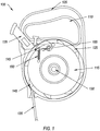
- Figure 1 illustrates an example of a retractable leash 100.
- a leash also called a lead or lead line
- a leash is a rope or similar material attached to the neck, head or body of an animal for restraint or control. On the animal, some leashes clip or tie to a collar, harness, or halter, while others go directly around the animal's neck.
- the length of the retractable leash 100 can be adjusted by a user as necessary to keep the animal as close as desired by the user.
- Figure 1 shows that the retractable leash 100 includes a housing 105.
- the housing substantially encloses the other parts of the retractable leash 100.
- substantially enclose shall mean that the housing 105 surrounds the other parts of the retractable leash 100 except for those parts that need to be exposed to allow the retractable leash 100 to operate in a normal manner, unless otherwise specified. That is, the housing 105 can be configured to keep the various parts of the retractable leash 100 together. I.e., the housing 105 can be configured to ensure that the other parts of the retractable leash 100 remain in the desired position to allow the parts to perform their desired functions. Additionally or alternatively, the housing 105 can be used to protect the parts from damage.
- Figure 1 also shows that the retractable leash 100 can include a handle 110.
- the handle 110 can allow a user to hold the retractable leash 100. That is, the handle 110 can allow a user to use the retractable leash 100 to control an animal.
- Figure 1 further shows that the retractable leash 100 includes a spool 115.
- the spool 115 includes a cylinder or spindle.
- the spool 115 can be circular in shape in order to allow easy winding and unwinding. That is, the spool 115 can be rotated, which will wind or unwind the spool, as discussed below.
- Figure 1 additionally shows that the retractable leash 100 includes a leash 120.
- the leash 120 can include any material which allows the retractable leash 100 to control an animal as desired by the user.
- the leash 120 can be made of any material which can withstand the force of the user and the animal pulling against one another.
- the leash 120 can be made of metal, leather, braided leather, nylon cord, nylon webbing or any other suitable material.
- Figure 1 also shows that the leash 120 can extend from the housing 105.
- the leash 120 can be extracted to any length desired, up to a maximum length, that allows the user to maintain control of the animal.
- the end of the leash 120 can include a clip that can be connected to a collar or harness placed on the animal.
- the leash 120 can be of the maximum length at which a user would feel comfortable controlling the animal. For example, if the user wishes to allow the animal to be between 15 and 25 feet away, the leash 120 can be 25 feet long.
- Figure 1 further shows that the leash 120 can be attached to and wound around the spool 115.
- the leash 120 wound around the spool 115 can allow the user to vary the length of the leash 120 which extends from the housing 105. That is, winding more of the leash 120 around spool 115 allows the leash 120 to extend a shorter distance from the housing 105. In contrast, winding less of the leash 120 around the spool 115 allows the leash 120 to extend a longer distance from the housing 105.
- Figure 1 additionally shows that the spool 115 can include a flange 125.
- the flange 125 can prevent the leash 120 from slipping off the spool 115. That is, as the leash 120 is wound around the outer surface of the spool 115, the flange 125 can prevent the leash 120 from slipping off of the outer surface.
- the housing 105 can fit tightly around the spool 115 preventing any slippage of the leash 120 relative to the spool 115.
- Figure 1 also shows that the spool 115 can include a central portion 130.
- the central portion 130 allows the spool 115 to rotate.
- the central portion 130 can hold the central point of the spool 115 in one location relative to the housing 105. That is, the central portion 130 holds the central point of the spool 115 immobile, except for rotational movement, within the housing 105.
- the spool 115 also can include a recoil spring.
- the recoil spring is configured to move the spool 115 back to its original position when the spool 115 has moved. That is, the recoil spring retains rotation energy when the leash 120 extends from the housing 105. When the leash 120 is released, the spring releases the rotational energy, causing the spool 115 to rotate and the leash 120 to wind around the spool 115.
- Figure 1 further shows that the retractable leash 100 includes a manual brake 135.
- the manual brake 135 can be used to prevent the spool 115 from rotating.
- the manual brake 135 can be pushed by a user to contact the spool 115.
- the spool 115 is prevented from rotating.
- the spool 115 can include one or more tabs 140.
- rotation of the spool 115 causes the one or more tabs 140 to come in contact with the manual brake 135, which prevents rotation of the spool 115.
- the manual brake 135 can include a thumb brake. That is, the manual brake 135 is configured to be near the user's thumb when the user is holding the handle 105 of the retractable leash 100.
- a thumb brake can allow the user to maintain his or her grip on the handle 105 while simultaneously engaging the manual brake 135. This is, the user can engage the manual brake 135 without loosening his or her grip on the handle 105.
- the manual brake 135 can include a lock.
- the lock can be configured to keep the manual brake engaged until disengaged by a user. That is, the lock can allow the user to prevent rotation of the spool 115 without needing to continue to push on the manual brake 135.
- Figure 1 additionally shows that the retractable leash 100 includes a cam 145.
- the cam 145 can include a disk or cylinder having an irregular form. That is, cam 145 can be shaped such that the diameter varies in different directions. A varying diameter can allow rotation of the cam 145 to bring the cam 145 into contact with, or avoid contact with, other objects depending on the orientation of the cam 145.
- the cam 145 can be substantially L shaped. That is, the cam 145 can include a first portion and a second portion that is perpendicular, or approximately perpendicular, to the first portion.
- Figure 1 also shows that the cam 145 can be attached to the spool 115.
- attaching the cam 145 to the spool 115 can allow the cam 145 to automatically stop the spool 115 from rotating faster than a certain rotational speed. That is, if the leash 120 is extracted from the housing 105 at a high rate of speed, the spool 115 will rotate quickly enough that the cam 145 will prevent further motion of the spool 115, as discussed below.
- Figure 1 further shows that the retractable leash 100 can include a retaining spring 150 attached to the cam 145.
- the retaining spring 150 is configured to pull the cam 145 toward the central portion 130 of the spool 115. That is, the retaining spring 150 can be used to ensure that the cam 145 does not come into contact with the housing 105 when the spool 115 is stationary or at low rotational speeds.
- Figure 1 additionally shows that the retractable leash 100 can include a stop 155.
- the stop 155 prevents the cam 145 from moving too far toward the central portion 130 of the spool 115.
- the stop 155 can prevent the retaining spring 150 from fully relaxing which keeps the cam 145 firmly against the stop 155.
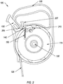
- Figure 2 illustrates an example of a retractable leash 100 in which an automatic brake has been applied.
- an automatic brake can stop the leash 120 from being extracted from the housing 105 if the leash 120 begins to be extracted too quickly. For example, if the leash 120 is connected to an animal that begins to run away, the automatic brake can stop the leash 120 from being extracted from the housing 105. Additionally or alternatively, the automatic brake can stop the leash 120 from being extracted from the housing 105 if the user stops and the animal continues to move away from the user.
- Figure 2 shows that the retractable leash 100 can include a catch 205.
- the catch 205 is configured to catch the cam 145. That is, if the centrifugal force from the spinning of the spool 115 is sufficient, the cam 145 will be pushed away from the center portion 130 and pull on the retaining spring 150. When the centrifugal force is sufficient, the cam will try to push beyond the outer circumference of the spool 115. For most of the outer circumference, the housing will prevent the cam 145 from pushing out too far. However, when the cam 145 reaches the catch 205 the cam 145 will enter the catch 205. The cam 145 is then stopped by the catch 205, which in turn can stop the spool 115 which is attached to the cam 145.
- the catch 205 can include a portion of the housing 105. That is, the catch 205 can include a portion of the housing 105 where the housing 105 is further from the spool 115 than other portions of the housing 105. Additionally or alternatively, the catch 205 can include a portion of the manual brake 135 or any other mechanism that is configured to catch the cam 145 and prevent it from moving.
- the rotational speed of the spool 115 necessary for the cam 145 to act against the retaining spring 150 and therefore move towards the outer circumference of the spool 115 is determined by the placement of the cam 145 relative to the outer edge of the spool 115, the type and placement of the retaining spring 150 and the mass of the cam 145.
- the cam 145 can be configured to enter the catch 205 when the leash is being extracted at between 0.30 meter per second, "m/s", (1 foot per second, "fps") and 0.61 m/s (2 fps).
- the cam 145 can be configured to enter the catch 205 at approximately 0.46 m/s (1.5 fps).
- the term approximately shall mean that the value is within 10% of the stated value, unless otherwise specified.
- the catch 205 can include a switch 207 which allows the user to prevent the cam 145 from entering the catch 205 if desired.
- the switch 207 can prevent the cam 145 from rotating relative to the spool 115. Additionally or alternatively, the switch 207 can prevent the cam 145 from entering the catch 205.
- the switch 207 can include a section of housing 105 which is movable and can be used to prevent the cam 145 from entering the catch 205.
- Figure 2 also shows that the retractable leash 100 can include a backstop 210.
- the backstop 210 can prevent further rotation of the cam 145. That is, the cam 145 will enter the catch 205 and the force of the cam 145 striking the catch 205 will tend to rotate the cam 145.
- the backstop 210 can prevent the cam 145 from rotating too far and exiting the catch 205 without stopping the spool 115.
- the backstop 210 can also help stop the spool 115 from rotating.
- the backstop 210 can provide a force point where the spool 115 strikes the cam 145 if the cam 145 has entered the catch 205. This can help ensure that the forces involved in stopping the spool 115 do not break the spool 115 or the cam 145.
- the retractable leash 100 can include a cam 145 on either side of the spool 115.
- a second cam 145 can be opposite the cam 145.
- the cam 145 and a second cam can work with one another to stop the spool 115 from rotating.
- the cam 145 and a second cam can be connected to one another through an axle which extends through the spool 115.
- a second cam and a second backstop can further reduce the force on the spool 115 as the cam 145 is stopped by the catch 205.
- Figure 3 illustrates an embodiment of a retractable leash 300.
- the retractable leash 300 includes an automatic braking system.
- the automatic braking system can stop the leash 120 from exiting the housing 105. I.e., as the animal begins to move away from the user at a high rate of speed, the automatic braking system can prevent the animal from attaining a high speed.
- Figure 3 shows that the retractable leash 300 includes a lever 305.
- the lever 305 can include a rigid object that can rotate about a fulcrum 310.
- the lever 305 can either multiply the mechanical force that can be applied to another object or resistance force, or multiply the distance and speed at which the opposite end of the lever 305 travels. I.e., a small amount of movement on one end of the lever 305 can be translated into a larger amount of movement at the opposite end of the lever 305.
- Figure 3 also shows that the retractable leash 300 includes a cam 145 attached to a spool 115.
- attaching the cam 145 to the spool 115 can allow the cam 145 to automatically stop the spool 115 from rotating faster than a certain rotational speed. That is, if the leash 120 is extracted from the housing 105 at a high rate of speed, the spool 115 will rotate quickly enough that the cam 145 will prevent further motion of the spool 115, as discussed below.
- Figure 3 further shows that the retractable leash 300 can include a retaining spring 150 attached to the cam 145.
- the retaining spring 150 is configured to pull the cam 145 toward the central portion 130 of the spool 115. That is, the retaining spring 150 can be used to ensure that the cam 145 does not come into contact with the lever 305 when the spool 115 is stationary or at low rotational speeds.
- Figure 3 additionally shows that as the spool 115 rotates at a high rate of speed, the cam 145 moves outward, making contact with the lever 305.
- the lever 305 makes contact with the manual brake 135.
- the cam 145 provides a sufficient amount of force on the first end of the lever 305 to move the manual brake 135 into position, stopping the rotation of the spool 115.
- the cam 145 can be configured to provide sufficient force to the lever 305 to engage the manual brake 135 when the leash is being extracted at between 0.30 meter per second, "m/s", (1 foot per second, "fps") and 0.61 m/s (2 fps).
- the cam 145 can be configured to provide sufficient force to the lever 305 to engage the manual brake 135 when the leash is being extracted at approximately 0.46 m/s (1.5 fps). The user can then, if desired, put pressure on the manual brake 135 preventing further rotation of the spool 115.
- the retractable leash 300 can include a switch 315 which allows the user to prevent lever 305 from engaging the manual brake 135, if desired.
- the switch 315 can prevent the cam 145 from rotating relative to the spool 115. Additionally or alternatively, the switch 315 can prevent the lever 305 from rotating about the fulcrum 310.
- the switch 315 can include a section of housing 105 which is movable and can be used to prevent the lever 305 from rotating about the fulcrum 310.
- Figure 4 illustrates an alternative implementation of a retractable leash 400.
- the retractable leash 400 can include an automatic braking system.
- the automatic braking system can stop the leash 120 from exiting the housing 105. I.e., as the animal begins to move away from the user at a high rate of speed, the automatic braking system can prevent the animal from attaining a high speed.
- Figure 4 shows that the retractable leash 400 can include a sliding member 405.
- the sliding member 405 can be attached to the spool 115. Attaching sliding member 405 to the spool 115 can allow the sliding member 405 to automatically stop the spool 115 from rotating faster than a certain rotational speed. That is, if the leash 120 is extracted from the housing 105 at a high rate of speed, the spool 115 will rotate quickly enough that the sliding member 405 will prevent further motion of the spool 115, as discussed below.
- Figure 4 also shows that the retractable leash 400 can include a guide 410.
- the guide 410 can control the motion of the sliding member 405. I.e., the guide 410 can ensure that the sliding member 405 moves only in a desired direction based on the rotational speed of the spool 115. In particular, the rotational motion of the spool 115 would cause the sliding member 405 to rotate in the absence of the guide 410.
- Figure 4 further shows that the retractable leash 400 can include a retaining spring 150 attached to the sliding member 405.
- the retaining spring 150 is configured to pull the sliding member 405 toward the central portion 130 of the spool 115. That is, the retaining spring 150 can be used to ensure that the sliding member 405 does not come into contact with the housing 105 when the spool 115 is stationary or at low rotational speeds.
- Figure 4 additionally shows that the retractable leash 400 can include a block 415.
- the block 415 prevents the sliding member 405 from moving too far toward the central portion 130 of the spool 115.
- the block 415 can prevent the retaining spring 150 from fully relaxing which keeps the sliding member 405 firmly against the block 415.
- Figure 4 also shows that the retractable leash 400 can include a housing stop 420.
- the housing stop 420 is configured to catch the sliding member 405. That is, if the centrifugal force from the spinning of the spool 115 is sufficient, the sliding member 405 will be pushed away from the center portion 130 and pull on the retaining spring 150. When the centrifugal force is sufficient, the sliding member 405 will try to push beyond the outer circumference of the spool 115. For most of the outer circumference, the housing will prevent the sliding member 405 from pushing out too far. However, when the sliding member 405 reaches the housing stop 420 the sliding member 405 will make contact with the housing stop 420. The sliding member 405 is then stopped by the housing stop 420, which in turn can stop the spool 115 which is attached to the sliding member 405.
- the housing stop 420 can include a portion of the housing 105. That is, the housing stop 420 can include a portion of the housing 105 where the housing 105 is further from the spool 115 than other portions of the housing 105. Additionally or alternatively, the housing stop 420 can include a portion of the manual brake 135 or any other mechanism that is configured to catch the sliding member 405 and prevent it from moving.
- the rotational speed of the spool 115 necessary for the sliding member 405 to act against the retaining spring 150 and therefore move towards the outer circumference of the spool 115 is determined by the placement of the sliding member 405 relative to the outer edge of the spool 115, the type and placement of the retaining spring 150 and the mass of the sliding member 405.
- the sliding member 405 can be configured to enter the housing stop 420 when the leash is being extracted at between 0.30 meter per second, "m/s", (1 foot per second, "fps") and 0.61 m/s (2 fps).
- the sliding member 405 can be configured to enter the housing stop 420 at approximately 0.46 m/s (1.5 fps).
- the housing stop 420 can include a switch 425 which allows the user to prevent the sliding member 405 from entering the housing stop 420 if desired.
- the switch 425 can prevent the sliding member 405 from rotating relative to the spool 115. Additionally or alternatively, the switch 425 can prevent the sliding member 405 from entering the housing stop 420.
- the switch 425 can include a section of housing 105 which is movable and can be used to prevent the sliding member 405 from entering the housing stop 420.
Landscapes
- Life Sciences & Earth Sciences (AREA)
- Environmental Sciences (AREA)
- Animal Husbandry (AREA)
- Biodiversity & Conservation Biology (AREA)
- Storing, Repeated Paying-Out, And Re-Storing Of Elongated Articles (AREA)
- Emergency Lowering Means (AREA)
- Braking Arrangements (AREA)
- Fittings On The Vehicle Exterior For Carrying Loads, And Devices For Holding Or Mounting Articles (AREA)
Description
- A favorite hobby of many pet owners is going for walks with their pet. For example, many dog and cat owners will often take their pet for a walk every day or almost every day. Unfortunately, this can lead to undesirable encounters. For example, pets can attack other animals or people. In addition, pets can become distracted and run away or run into the street where they can be hit and killed. Because of these dangers, many states and cities now have ordinances requiring pets to be on a leash when outdoors.
- A particularly popular type of leash among pet owners is a retractable leash, such as the one known from
US 2007/022975 A1 . A retractable leash can allow the pet owner to vary the distance that the pet can be from the owner at any given time. In particular, the owner can allow the pet to wander farther away when it is safe to do so and keep the pet closer when it would be unsafe for the pet to wander. - Retractable leashes often let out leash unless a brake is applied. That is, the default is that as the pet walks farther away, the retractable leash lengthens to accommodate the pet unless it is set to not let out any more leash. This can increase the danger for the pet and the pet owner. For example, if the owner sees danger, such as a car or another pet, the pet can continue to walk.
- In addition, there is a danger if the pet begins to run away. By the time the pet owner has a chance to apply a brake, the pet may already have momentum away from the pet owner. That is, by the time the pet owner reacts to the pet running away, the pet may already be at a high rate of speed. If the pet owner then applies a brake or the leash reaches the full length all of the momentum acts as a force on the pet owner, pulling him or her in the direction of the running pet.
- This can lead to discomfort or injury for the pet owner. For example, it can pull on the pet owner's arm or can pull the pet owner off his or her feet. The pet owner then has to try to prevent injury while simultaneously trying to regain control of the pet. In particular, the pet owner might continue to have a pet pulling them in one direction while simultaneously attempting to break his or her fall.
- This can also lead to discomfort or injury to the pet. In particular, many leashes are attached to a pet via a collar. A collar is a piece of material placed around the pet's neck. This means that as the pet reaches the end of the leash or the owner applies the leash brake, the force applied by the owner to stop the pet's momentum is applied to the pet's neck which can cause injury to the pet's windpipe or vertebrae.
- Accordingly, there is a need in the art for a leash that includes an automatic brake. Additionally, there is a need for the automatic brake to be applied quickly, before the pet has a chance to build up momentum.
-
WO 2005/080149 A1 discloses a restraint means for restricting the relative movement of two persons, wherein the restraint means has a body which is attached to a first person. The body has a rotating drum from which a connecting cable is fed. The remote end of the cable has an attachment member for attaching the cable to a second person, such as a child, for example. -
DE 20313853 U1 discloses a hand carried reel with an extending lead for securing animals having a housing to hold a spring loaded reel and a hand grip near to a thumb-operated release and brake control. The reel is also fitted with magnetically held centrifugal elements which are released at a preset speed for unreeling the lead and engage a braking system to slow the release of the lead. The braking system can be friction plates or a simple hydraulic brake. - The present invention provides a retractable leash for restraining an animal attached to the retractable leash as featured in independent claim 1. Details of the present invention are described in the present description.
- This Summary is provided to introduce a selection of concepts in a simplified form that are further described below in the Detailed Description. This Summary is not intended to identify key features or essential characteristics of the claimed subject matter, nor is it intended to be used as an aid in determining the scope of the claimed subject matter.
- One example includes a retractable leash for restraining an animal attached to the retractable leash. The retractable leash includes a housing, where the housing is configured to substantially cover the other parts of the retractable leash. The retractable leash also includes a spool in the housing and a leash. The leash is wound around the spool and at least a portion of the leash can be extracted from the housing. The retractable leash further includes an automatic brake, where the automatic brake is configured to lock the leash and prevent further extraction of the leash from the housing if the leash is extracted above a threshold speed.
- Another example includes a retractable leash for restraining an animal attached to the retractable leash. The retractable leash includes a housing and a spool in the housing. The retractable leash also includes a leash, where the leash is wound around the spool and at least a portion of the leash can be extracted from the housing. The retractable leash further includes an automatic braking means, where the automatic braking means is configured to lock the leash and prevent further extraction of the leash from the housing if the leash is extracted at high speed.
- These and other objects and features of the present invention will become more fully apparent from the following description and appended claims, or may be learned by the practice of the invention as set forth hereinafter.
- To further clarify various aspects of some example embodiments of the present invention, a more particular description of the invention will be rendered by reference to specific embodiments thereof which are illustrated in the appended drawings. It is appreciated that these drawings depict only illustrated embodiments of the invention and are therefore not to be considered limiting of its scope. The invention will be described and explained with additional specificity and detail through the use of the accompanying drawings in which:
-
Figure 1 illustrates an example of a retractable leash; -
Figure 2 illustrates an example of a retractable leash in which an automatic brake has been applied; -
Figure 3 illustrates an alternative implementation of a retractable leash; and -
Figure 4 illustrates an alternative implementation of a retractable leash. - Reference will now be made to the figures wherein like structures will be provided with like reference designations. It is understood that the figures are diagrammatic and schematic representations of some embodiments of the invention, and are not limiting of the present invention, nor are they necessarily drawn to scale.
-
Figure 1 illustrates an example of aretractable leash 100. In at least one implementation, a leash (also called a lead or lead line) is a rope or similar material attached to the neck, head or body of an animal for restraint or control. On the animal, some leashes clip or tie to a collar, harness, or halter, while others go directly around the animal's neck. In at least one implementation, the length of theretractable leash 100 can be adjusted by a user as necessary to keep the animal as close as desired by the user. -
Figure 1 shows that theretractable leash 100 includes ahousing 105. In at least one implementation, the housing substantially encloses the other parts of theretractable leash 100. As used in the specification and the claims, substantially enclose shall mean that thehousing 105 surrounds the other parts of theretractable leash 100 except for those parts that need to be exposed to allow theretractable leash 100 to operate in a normal manner, unless otherwise specified. That is, thehousing 105 can be configured to keep the various parts of theretractable leash 100 together. I.e., thehousing 105 can be configured to ensure that the other parts of theretractable leash 100 remain in the desired position to allow the parts to perform their desired functions. Additionally or alternatively, thehousing 105 can be used to protect the parts from damage. -
Figure 1 also shows that theretractable leash 100 can include ahandle 110. In at least one implementation, thehandle 110 can allow a user to hold theretractable leash 100. That is, thehandle 110 can allow a user to use theretractable leash 100 to control an animal. -
Figure 1 further shows that theretractable leash 100 includes aspool 115. In at least one implementation, thespool 115 includes a cylinder or spindle. In particular, thespool 115 can be circular in shape in order to allow easy winding and unwinding. That is, thespool 115 can be rotated, which will wind or unwind the spool, as discussed below. -
Figure 1 additionally shows that theretractable leash 100 includes aleash 120. Theleash 120 can include any material which allows theretractable leash 100 to control an animal as desired by the user. In particular, theleash 120 can be made of any material which can withstand the force of the user and the animal pulling against one another. For example, theleash 120 can be made of metal, leather, braided leather, nylon cord, nylon webbing or any other suitable material. -
Figure 1 also shows that theleash 120 can extend from thehousing 105. In at least implementation, theleash 120 can be extracted to any length desired, up to a maximum length, that allows the user to maintain control of the animal. In particular, the end of theleash 120 can include a clip that can be connected to a collar or harness placed on the animal. Theleash 120 can be of the maximum length at which a user would feel comfortable controlling the animal. For example, if the user wishes to allow the animal to be between 15 and 25 feet away, theleash 120 can be 25 feet long. -
Figure 1 further shows that theleash 120 can be attached to and wound around thespool 115. In at least one implementation, theleash 120 wound around thespool 115 can allow the user to vary the length of theleash 120 which extends from thehousing 105. That is, winding more of theleash 120 aroundspool 115 allows theleash 120 to extend a shorter distance from thehousing 105. In contrast, winding less of theleash 120 around thespool 115 allows theleash 120 to extend a longer distance from thehousing 105. -
Figure 1 additionally shows that thespool 115 can include aflange 125. In at least one implementation, theflange 125 can prevent theleash 120 from slipping off thespool 115. That is, as theleash 120 is wound around the outer surface of thespool 115, theflange 125 can prevent theleash 120 from slipping off of the outer surface. Additionally or alternatively, thehousing 105 can fit tightly around thespool 115 preventing any slippage of theleash 120 relative to thespool 115. -
Figure 1 also shows that thespool 115 can include acentral portion 130. In at least one implementation, thecentral portion 130 allows thespool 115 to rotate. In particular, thecentral portion 130 can hold the central point of thespool 115 in one location relative to thehousing 105. That is, thecentral portion 130 holds the central point of thespool 115 immobile, except for rotational movement, within thehousing 105. - In at least one implementation, the
spool 115 also can include a recoil spring. In at least one implementation, the recoil spring is configured to move thespool 115 back to its original position when thespool 115 has moved. That is, the recoil spring retains rotation energy when theleash 120 extends from thehousing 105. When theleash 120 is released, the spring releases the rotational energy, causing thespool 115 to rotate and theleash 120 to wind around thespool 115. -
Figure 1 further shows that theretractable leash 100 includes amanual brake 135. In at least one implementation, themanual brake 135 can be used to prevent thespool 115 from rotating. In particular, themanual brake 135 can be pushed by a user to contact thespool 115. As themanual brake 135 comes in contact with thespool 115, thespool 115 is prevented from rotating. For example, thespool 115 can include one ormore tabs 140. When themanual brake 135 is engaged, rotation of thespool 115 causes the one ormore tabs 140 to come in contact with themanual brake 135, which prevents rotation of thespool 115. - In at least one implementation, the
manual brake 135 can include a thumb brake. That is, themanual brake 135 is configured to be near the user's thumb when the user is holding thehandle 105 of theretractable leash 100. A thumb brake can allow the user to maintain his or her grip on thehandle 105 while simultaneously engaging themanual brake 135. This is, the user can engage themanual brake 135 without loosening his or her grip on thehandle 105. - In at least one implementation, the
manual brake 135 can include a lock. In particular, the lock can be configured to keep the manual brake engaged until disengaged by a user. That is, the lock can allow the user to prevent rotation of thespool 115 without needing to continue to push on themanual brake 135. -
Figure 1 additionally shows that theretractable leash 100 includes acam 145. In at least one implementation, thecam 145 can include a disk or cylinder having an irregular form. That is,cam 145 can be shaped such that the diameter varies in different directions. A varying diameter can allow rotation of thecam 145 to bring thecam 145 into contact with, or avoid contact with, other objects depending on the orientation of thecam 145. For example, thecam 145 can be substantially L shaped. That is, thecam 145 can include a first portion and a second portion that is perpendicular, or approximately perpendicular, to the first portion. -
Figure 1 also shows that thecam 145 can be attached to thespool 115. In at least one implementation, attaching thecam 145 to thespool 115 can allow thecam 145 to automatically stop thespool 115 from rotating faster than a certain rotational speed. That is, if theleash 120 is extracted from thehousing 105 at a high rate of speed, thespool 115 will rotate quickly enough that thecam 145 will prevent further motion of thespool 115, as discussed below. -
Figure 1 further shows that theretractable leash 100 can include a retainingspring 150 attached to thecam 145. In at least one implementation, the retainingspring 150 is configured to pull thecam 145 toward thecentral portion 130 of thespool 115. That is, the retainingspring 150 can be used to ensure that thecam 145 does not come into contact with thehousing 105 when thespool 115 is stationary or at low rotational speeds. -
Figure 1 additionally shows that theretractable leash 100 can include astop 155. In at least one implementation, thestop 155 prevents thecam 145 from moving too far toward thecentral portion 130 of thespool 115. In particular, thestop 155 can prevent the retainingspring 150 from fully relaxing which keeps thecam 145 firmly against thestop 155. -
Figure 2 illustrates an example of aretractable leash 100 in which an automatic brake has been applied. In at least one implementation, an automatic brake can stop theleash 120 from being extracted from thehousing 105 if theleash 120 begins to be extracted too quickly. For example, if theleash 120 is connected to an animal that begins to run away, the automatic brake can stop theleash 120 from being extracted from thehousing 105. Additionally or alternatively, the automatic brake can stop theleash 120 from being extracted from thehousing 105 if the user stops and the animal continues to move away from the user. -
Figure 2 shows that theretractable leash 100 can include acatch 205. In at least one implementation, thecatch 205 is configured to catch thecam 145. That is, if the centrifugal force from the spinning of thespool 115 is sufficient, thecam 145 will be pushed away from thecenter portion 130 and pull on the retainingspring 150. When the centrifugal force is sufficient, the cam will try to push beyond the outer circumference of thespool 115. For most of the outer circumference, the housing will prevent thecam 145 from pushing out too far. However, when thecam 145 reaches thecatch 205 thecam 145 will enter thecatch 205. Thecam 145 is then stopped by thecatch 205, which in turn can stop thespool 115 which is attached to thecam 145. - In at least one implementation, the
catch 205 can include a portion of thehousing 105. That is, thecatch 205 can include a portion of thehousing 105 where thehousing 105 is further from thespool 115 than other portions of thehousing 105. Additionally or alternatively, thecatch 205 can include a portion of themanual brake 135 or any other mechanism that is configured to catch thecam 145 and prevent it from moving. - In at least one implementation, the rotational speed of the
spool 115 necessary for thecam 145 to act against the retainingspring 150 and therefore move towards the outer circumference of thespool 115 is determined by the placement of thecam 145 relative to the outer edge of thespool 115, the type and placement of the retainingspring 150 and the mass of thecam 145. For example, thecam 145 can be configured to enter thecatch 205 when the leash is being extracted at between 0.30 meter per second, "m/s", (1 foot per second, "fps") and 0.61 m/s (2 fps). In particular, thecam 145 can be configured to enter thecatch 205 at approximately 0.46 m/s (1.5 fps). As used in the specification and the claims, the term approximately shall mean that the value is within 10% of the stated value, unless otherwise specified. - In at least one implementation, the
catch 205 can include aswitch 207 which allows the user to prevent thecam 145 from entering thecatch 205 if desired. For example, theswitch 207 can prevent thecam 145 from rotating relative to thespool 115. Additionally or alternatively, theswitch 207 can prevent thecam 145 from entering thecatch 205. For example, theswitch 207 can include a section ofhousing 105 which is movable and can be used to prevent thecam 145 from entering thecatch 205. -
Figure 2 also shows that theretractable leash 100 can include abackstop 210. In at least one implementation, thebackstop 210 can prevent further rotation of thecam 145. That is, thecam 145 will enter thecatch 205 and the force of thecam 145 striking thecatch 205 will tend to rotate thecam 145. Thebackstop 210 can prevent thecam 145 from rotating too far and exiting thecatch 205 without stopping thespool 115. - In at least one implementation, the
backstop 210 can also help stop thespool 115 from rotating. In particular, thebackstop 210 can provide a force point where thespool 115 strikes thecam 145 if thecam 145 has entered thecatch 205. This can help ensure that the forces involved in stopping thespool 115 do not break thespool 115 or thecam 145. - In at least one implementation, the
retractable leash 100 can include acam 145 on either side of thespool 115. In particular, asecond cam 145 can be opposite thecam 145. Thecam 145 and a second cam can work with one another to stop thespool 115 from rotating. For example, thecam 145 and a second cam can be connected to one another through an axle which extends through thespool 115. As thespool 115 rotates rapidly the centrifugal force on thecam 145 and the second cam can be equalized such that both or neither enter thecatch 205 depending on the speed of rotation. A second cam and a second backstop can further reduce the force on thespool 115 as thecam 145 is stopped by thecatch 205. -
Figure 3 illustrates an embodiment of aretractable leash 300. In at least one implementation, theretractable leash 300 includes an automatic braking system. In particular, the automatic braking system can stop theleash 120 from exiting thehousing 105. I.e., as the animal begins to move away from the user at a high rate of speed, the automatic braking system can prevent the animal from attaining a high speed. -
Figure 3 shows that theretractable leash 300 includes alever 305. In at least one implementation, thelever 305 can include a rigid object that can rotate about afulcrum 310. In particular, thelever 305 can either multiply the mechanical force that can be applied to another object or resistance force, or multiply the distance and speed at which the opposite end of thelever 305 travels. I.e., a small amount of movement on one end of thelever 305 can be translated into a larger amount of movement at the opposite end of thelever 305. -
Figure 3 also shows that theretractable leash 300 includes acam 145 attached to aspool 115. In at least one implementation, attaching thecam 145 to thespool 115 can allow thecam 145 to automatically stop thespool 115 from rotating faster than a certain rotational speed. That is, if theleash 120 is extracted from thehousing 105 at a high rate of speed, thespool 115 will rotate quickly enough that thecam 145 will prevent further motion of thespool 115, as discussed below. -
Figure 3 further shows that theretractable leash 300 can include a retainingspring 150 attached to thecam 145. In at least one implementation, the retainingspring 150 is configured to pull thecam 145 toward thecentral portion 130 of thespool 115. That is, the retainingspring 150 can be used to ensure that thecam 145 does not come into contact with thelever 305 when thespool 115 is stationary or at low rotational speeds. -
Figure 3 additionally shows that as thespool 115 rotates at a high rate of speed, thecam 145 moves outward, making contact with thelever 305. Thelever 305, in turn, makes contact with themanual brake 135. As the speed exceeds a threshold limit, thecam 145 provides a sufficient amount of force on the first end of thelever 305 to move themanual brake 135 into position, stopping the rotation of thespool 115. For example, thecam 145 can be configured to provide sufficient force to thelever 305 to engage themanual brake 135 when the leash is being extracted at between 0.30 meter per second, "m/s", (1 foot per second, "fps") and 0.61 m/s (2 fps). In particular, thecam 145 can be configured to provide sufficient force to thelever 305 to engage themanual brake 135 when the leash is being extracted at approximately 0.46 m/s (1.5 fps). The user can then, if desired, put pressure on themanual brake 135 preventing further rotation of thespool 115. - In at least one implementation, the
retractable leash 300 can include aswitch 315 which allows the user to preventlever 305 from engaging themanual brake 135, if desired. For example, theswitch 315 can prevent thecam 145 from rotating relative to thespool 115. Additionally or alternatively, theswitch 315 can prevent thelever 305 from rotating about thefulcrum 310. For example, theswitch 315 can include a section ofhousing 105 which is movable and can be used to prevent thelever 305 from rotating about thefulcrum 310. -
Figure 4 illustrates an alternative implementation of aretractable leash 400. In at least one implementation, theretractable leash 400 can include an automatic braking system. In particular, the automatic braking system can stop theleash 120 from exiting thehousing 105. I.e., as the animal begins to move away from the user at a high rate of speed, the automatic braking system can prevent the animal from attaining a high speed. -
Figure 4 shows that theretractable leash 400 can include a slidingmember 405. In at least one implementation, the slidingmember 405 can be attached to thespool 115. Attaching slidingmember 405 to thespool 115 can allow the slidingmember 405 to automatically stop thespool 115 from rotating faster than a certain rotational speed. That is, if theleash 120 is extracted from thehousing 105 at a high rate of speed, thespool 115 will rotate quickly enough that the slidingmember 405 will prevent further motion of thespool 115, as discussed below. -
Figure 4 also shows that theretractable leash 400 can include aguide 410. In at least one implementation, theguide 410 can control the motion of the slidingmember 405. I.e., theguide 410 can ensure that the slidingmember 405 moves only in a desired direction based on the rotational speed of thespool 115. In particular, the rotational motion of thespool 115 would cause the slidingmember 405 to rotate in the absence of theguide 410. -
Figure 4 further shows that theretractable leash 400 can include a retainingspring 150 attached to the slidingmember 405. In at least one implementation, the retainingspring 150 is configured to pull the slidingmember 405 toward thecentral portion 130 of thespool 115. That is, the retainingspring 150 can be used to ensure that the slidingmember 405 does not come into contact with thehousing 105 when thespool 115 is stationary or at low rotational speeds. -
Figure 4 additionally shows that theretractable leash 400 can include ablock 415. In at least one implementation, theblock 415 prevents the slidingmember 405 from moving too far toward thecentral portion 130 of thespool 115. In particular, theblock 415 can prevent the retainingspring 150 from fully relaxing which keeps the slidingmember 405 firmly against theblock 415. -
Figure 4 also shows that theretractable leash 400 can include ahousing stop 420. In at least one implementation, thehousing stop 420 is configured to catch the slidingmember 405. That is, if the centrifugal force from the spinning of thespool 115 is sufficient, the slidingmember 405 will be pushed away from thecenter portion 130 and pull on the retainingspring 150. When the centrifugal force is sufficient, the slidingmember 405 will try to push beyond the outer circumference of thespool 115. For most of the outer circumference, the housing will prevent the slidingmember 405 from pushing out too far. However, when the slidingmember 405 reaches thehousing stop 420 the slidingmember 405 will make contact with thehousing stop 420. The slidingmember 405 is then stopped by thehousing stop 420, which in turn can stop thespool 115 which is attached to the slidingmember 405. - In at least one implementation, the
housing stop 420 can include a portion of thehousing 105. That is, thehousing stop 420 can include a portion of thehousing 105 where thehousing 105 is further from thespool 115 than other portions of thehousing 105. Additionally or alternatively, thehousing stop 420 can include a portion of themanual brake 135 or any other mechanism that is configured to catch the slidingmember 405 and prevent it from moving. - In at least one implementation, the rotational speed of the
spool 115 necessary for the slidingmember 405 to act against the retainingspring 150 and therefore move towards the outer circumference of thespool 115 is determined by the placement of the slidingmember 405 relative to the outer edge of thespool 115, the type and placement of the retainingspring 150 and the mass of the slidingmember 405. For example, the slidingmember 405 can be configured to enter thehousing stop 420 when the leash is being extracted at between 0.30 meter per second, "m/s", (1 foot per second, "fps") and 0.61 m/s (2 fps). In particular, the slidingmember 405 can be configured to enter thehousing stop 420 at approximately 0.46 m/s (1.5 fps). - In at least one implementation, the
housing stop 420 can include aswitch 425 which allows the user to prevent the slidingmember 405 from entering thehousing stop 420 if desired. For example, theswitch 425 can prevent the slidingmember 405 from rotating relative to thespool 115. Additionally or alternatively, theswitch 425 can prevent the slidingmember 405 from entering thehousing stop 420. For example, theswitch 425 can include a section ofhousing 105 which is movable and can be used to prevent the slidingmember 405 from entering thehousing stop 420.
Claims (2)
- A retractable leash (300) for restraining an animal attached to the retractable leash (300), the retractable leash (300) comprising a housing (105), wherein the housing (105) is configured to substantially cover the other parts of the retractable leash (300), a spool (115) in the housing (105), a leash (120), wherein the leash (120) is wound around the spool (115) and at least a portion of the leash (120) can be extracted from the housing (105), an automatic brake, wherein the automatic brake is configured to lock the leash (120) and prevent further extraction of the leash (120) from the housing (105) if the leash (120) is extracted above a threshold speed, a manual brake (135), wherein the manual brake (135) is configured to prevent rotation of the spool (115) when engaged by a user and wherein the automatic brake is configured to engage the manual brake (135), said automatic brake comprising:a cam (145), wherein the cam (145) is configured to be forced outward against the housing (105) when the spool (115) rotates above the threshold speed; said retractable leash (300) being characterized in that said automatic brake further comprises:a lever (305), wherein one end of the lever (305) is configured to be moved by the cam (145) when the spool (115) rotates above the threshold speed and the other end of the lever (305) engages the manual brake (135).
- The retractable leash (300) of claim 1, wherein the lever (305) is pivotally connected to the housing (105).
Applications Claiming Priority (2)
| Application Number | Priority Date | Filing Date | Title |
|---|---|---|---|
| US12/891,615 US8516979B2 (en) | 2010-09-27 | 2010-09-27 | Retractable leash with automatic braking mechanism |
| PCT/US2011/053386 WO2012047623A2 (en) | 2010-09-27 | 2011-09-27 | Retractable leash with automatic braking mechanism |
Publications (3)
| Publication Number | Publication Date |
|---|---|
| EP2621265A2 EP2621265A2 (en) | 2013-08-07 |
| EP2621265A4 EP2621265A4 (en) | 2014-07-23 |
| EP2621265B1 true EP2621265B1 (en) | 2018-02-28 |
Family
ID=45869337
Family Applications (1)
| Application Number | Title | Priority Date | Filing Date |
|---|---|---|---|
| EP11831273.5A Not-in-force EP2621265B1 (en) | 2010-09-27 | 2011-09-27 | Retractable leash with automatic braking mechanism |
Country Status (8)
| Country | Link |
|---|---|
| US (1) | US8516979B2 (en) |
| EP (1) | EP2621265B1 (en) |
| JP (1) | JP5871934B2 (en) |
| CN (1) | CN103717061B (en) |
| AU (1) | AU2011312496A1 (en) |
| BR (1) | BR112013007249A2 (en) |
| CA (1) | CA2812770C (en) |
| WO (1) | WO2012047623A2 (en) |
Cited By (1)
| Publication number | Priority date | Publication date | Assignee | Title |
|---|---|---|---|---|
| WO2020148262A1 (en) | 2019-01-14 | 2020-07-23 | Polar Metalli Oy | Leash assembly |
Families Citing this family (26)
| Publication number | Priority date | Publication date | Assignee | Title |
|---|---|---|---|---|
| US9155287B2 (en) * | 2010-07-01 | 2015-10-13 | MerchSource, LLC | Retractable pet leash with bag container and removable flashlight |
| CN102134022B (en) * | 2011-03-31 | 2013-09-25 | 浙江天下实业有限公司 | Emergency self-locking pet tractor |
| US20130276717A1 (en) * | 2012-04-19 | 2013-10-24 | Victoria A. Fuller | Harness |
| CN102907336B (en) * | 2012-11-06 | 2013-11-06 | 东莞市佳晟实业有限公司 | Single-button type dog leash wire wheel brake switch |
| WO2014151948A1 (en) * | 2013-03-15 | 2014-09-25 | Advanced Practical Products, LLC | Retractor mechanism for collars |
| SI24376A (en) | 2013-06-07 | 2014-12-31 | Lishinu D.O.O. | Mechanism of leashes for pets with an automatic stop expiry string |
| US20150359196A1 (en) * | 2014-06-12 | 2015-12-17 | Crucs Holdings, Llc | Retractable leash with end-of-leash warning |
| US9339014B1 (en) | 2014-08-26 | 2016-05-17 | Richard Thomas | Retractable leash with gradual braking |
| USD828649S1 (en) * | 2015-02-25 | 2018-09-11 | Flexi-Bogdahn Technik Gmbh & Co. Kg | Dog leash reel |
| CN107846868A (en) * | 2015-05-08 | 2018-03-27 | 美国道科制造有限公司 | Scalable band |
| DE102015109444B4 (en) * | 2015-06-12 | 2018-08-02 | Bornack Gmbh & Co. Kg | Rope securing device |
| GB2539403A (en) * | 2015-06-15 | 2016-12-21 | Techsynergy Ltd | Retractable animal leash |
| CN105494142B (en) * | 2016-01-19 | 2020-12-01 | 必然科技有限公司 | Multifunctional pet tractor |
| US10265555B2 (en) * | 2016-06-17 | 2019-04-23 | Fang-Kuan Wu | Anti-falling device with rope retractable system |
| US10166907B2 (en) * | 2016-10-31 | 2019-01-01 | Valeda Company | Retractor with space-saving features |
| WO2018157308A1 (en) * | 2017-02-28 | 2018-09-07 | 深圳龙海特机器人科技有限公司 | Lockable type rope winding device |
| US10516258B2 (en) * | 2017-03-17 | 2019-12-24 | AI Incorporated | Retractable cable assembly in use with electrical devices |
| CA3063039C (en) * | 2017-05-15 | 2021-12-14 | Artem Anatolievich SOYUZOV | Retractable leash |
| TWI640245B (en) * | 2017-08-22 | 2018-11-11 | 劉純堅 | Retractable leash |
| US10829341B2 (en) | 2018-09-12 | 2020-11-10 | Taiwan Tarkey Products Inc. | Locking mechanism for pet retractor |
| CN113347877A (en) * | 2018-11-19 | 2021-09-03 | 安宝罗营销公司 | Palm activated telescopic traction rope |
| CN113573579B (en) * | 2019-03-13 | 2022-08-26 | 约翰·埃里克·查普曼 | Telescopic animal traction belt |
| CN110255297A (en) * | 2019-05-21 | 2019-09-20 | 梁若鹏 | A kind of novel pet retractor |
| US11596126B2 (en) * | 2020-06-30 | 2023-03-07 | Jw Pet Products Llc | Powered smart dog tether |
| CN114271211B (en) * | 2021-06-18 | 2023-08-01 | 吕俊武 | Pet tractor with fixed and accelerating double locking structure |
| US11833994B1 (en) | 2021-11-29 | 2023-12-05 | Clinton A. Sadler | Pet safety restraint device for vehicles |
Family Cites Families (28)
| Publication number | Priority date | Publication date | Assignee | Title |
|---|---|---|---|---|
| US2791397A (en) * | 1954-11-24 | 1957-05-07 | Inland Steel Co | Safety reel |
| US3853283A (en) | 1973-06-04 | 1974-12-10 | J Croce | Retractable leash device |
| GB1552667A (en) * | 1977-10-07 | 1979-09-19 | Barrow Hepburn Equip Ltd | Self winding drum |
| DE3040143A1 (en) | 1980-10-24 | 1982-05-27 | Desco-Werk Seger & Angermeyer Gmbh & Co, 7516 Karlsbad | DEVICE WITH A FLYING BRAKE, ESPECIALLY FOR THE SELF-REWINDING OF A CONNECTION LINE |
| US4501230A (en) | 1983-01-10 | 1985-02-26 | Talo Arnold T | Retracting and locking animal leash |
| GB9027783D0 (en) * | 1990-12-21 | 1991-02-13 | Barrow Hepburn Sala Ltd | Safety anchorages for controlling pay-out of a safety line |
| DE9304693U1 (en) | 1993-03-24 | 1993-06-09 | Bogdahn Technik GmbH, 2072 Bargteheide | Retractable animal leash |
| DE4345457C2 (en) * | 1993-09-13 | 2002-07-04 | Autoliv Dev | Belt retractor-belt tensioner combination with force limiter |
| DE4333760A1 (en) * | 1993-10-04 | 1995-04-06 | Trw Repa Gmbh | Belt retractor for restraint systems in vehicles |
| US5771993A (en) * | 1996-06-14 | 1998-06-30 | Dalloz Safety, Inc. | Safety devices for fall restraint |
| DE20008014U1 (en) * | 2000-05-05 | 2000-08-03 | Müller, Roland, 66453 Gersheim | Animal wrapping line |
| AU2002952251A0 (en) * | 2002-10-25 | 2002-11-07 | Terry Victor Lee | Escape device |
| US7040257B2 (en) | 2003-05-27 | 2006-05-09 | Jared Waxman | Retractable leash device |
| DE20310137U1 (en) * | 2003-07-01 | 2004-11-11 | Flexi-Bogdahn Technik Gmbh & Co. Kg | Leash device for a rope that can be rolled up and unrolled to guide animals |
| DE20313853U1 (en) | 2003-09-06 | 2003-12-04 | Flexi-Bogdahn Technik Gmbh & Co. Kg | Hand carried reel fitted lead for animal is fitted with centrifugal elements which operate a brake when the lead is pulled out above a set speed |
| DE10343112A1 (en) * | 2003-09-13 | 2005-04-07 | Ferplast S.P.A. | Dog leash |
| JP3102893U (en) * | 2004-01-20 | 2004-07-15 | 鶴進 陳 | Pipe winder |
| US7909004B2 (en) | 2004-01-20 | 2011-03-22 | Thompson Spencer J | Cam-lock leash |
| GB0404009D0 (en) * | 2004-02-21 | 2004-03-31 | Connell Alexander | Hands free child restraint means |
| JP2006014649A (en) * | 2004-07-01 | 2006-01-19 | Kushima Tomoyuki | Lead for pet |
| CN2798578Y (en) * | 2005-05-09 | 2006-07-26 | 何理才 | Freely telescopic pet-towing device |
| WO2008025349A1 (en) * | 2006-09-01 | 2008-03-06 | Ferplast S.P.A. | Animal leash, in particular for a dog |
| JP2008061631A (en) * | 2006-09-04 | 2008-03-21 | Tadashi Watanabe | Fixing reel-type extensible lead for pet |
| US8251304B2 (en) * | 2008-01-29 | 2012-08-28 | Conax Florida Corporation | Reel lock for passenger restraint having dual locking positions |
| US20100107992A1 (en) * | 2008-11-03 | 2010-05-06 | Chefetz Nathan S | Gentle stop retractable leash |
| CN201414334Y (en) * | 2009-04-07 | 2010-03-03 | 何理才 | Pet retractor |
| CN201585322U (en) * | 2009-12-08 | 2010-09-22 | 苏州佩德漫特工贸有限公司 | One-touch automatic tractor |
| US8251020B2 (en) * | 2010-03-12 | 2012-08-28 | Unleashed Products, LLC | Leash having a speed-limiting braking mechanism and system and method for using same |
-
2010
- 2010-09-27 US US12/891,615 patent/US8516979B2/en active Active
-
2011
- 2011-09-27 CN CN201180056793.3A patent/CN103717061B/en active Active
- 2011-09-27 AU AU2011312496A patent/AU2011312496A1/en not_active Abandoned
- 2011-09-27 JP JP2013530413A patent/JP5871934B2/en not_active Expired - Fee Related
- 2011-09-27 EP EP11831273.5A patent/EP2621265B1/en not_active Not-in-force
- 2011-09-27 CA CA2812770A patent/CA2812770C/en active Active
- 2011-09-27 BR BR112013007249A patent/BR112013007249A2/en not_active IP Right Cessation
- 2011-09-27 WO PCT/US2011/053386 patent/WO2012047623A2/en active Application Filing
Non-Patent Citations (1)
| Title |
|---|
| None * |
Cited By (1)
| Publication number | Priority date | Publication date | Assignee | Title |
|---|---|---|---|---|
| WO2020148262A1 (en) | 2019-01-14 | 2020-07-23 | Polar Metalli Oy | Leash assembly |
Also Published As
| Publication number | Publication date |
|---|---|
| JP2013541948A (en) | 2013-11-21 |
| AU2011312496A1 (en) | 2013-05-23 |
| WO2012047623A2 (en) | 2012-04-12 |
| WO2012047623A3 (en) | 2012-07-05 |
| BR112013007249A2 (en) | 2016-06-14 |
| CN103717061A (en) | 2014-04-09 |
| US8516979B2 (en) | 2013-08-27 |
| CN103717061B (en) | 2015-09-09 |
| EP2621265A4 (en) | 2014-07-23 |
| CA2812770A1 (en) | 2012-04-12 |
| EP2621265A2 (en) | 2013-08-07 |
| JP5871934B2 (en) | 2016-03-01 |
| US20120073516A1 (en) | 2012-03-29 |
| CA2812770C (en) | 2020-08-18 |
Similar Documents
| Publication | Publication Date | Title |
|---|---|---|
| EP2621265B1 (en) | Retractable leash with automatic braking mechanism | |
| US8251020B2 (en) | Leash having a speed-limiting braking mechanism and system and method for using same | |
| US20130284114A1 (en) | Slow-pull dog leash | |
| US8336505B2 (en) | Ring-shaped retractable pet lead | |
| US20140263799A1 (en) | Retractor Mechanism For Collars | |
| US20120118666A1 (en) | Rope climbing apparatus | |
| EP0580309A1 (en) | Ball game training device | |
| JP6981681B2 (en) | Stretchable towline for dogs and other pets | |
| EP2584892A1 (en) | Combination retractable leash assembly and wearable locket for companion pet | |
| US20170000088A1 (en) | Retractable leash | |
| US20190014748A1 (en) | System For Securing A Safety Device To A Leash | |
| US7909004B2 (en) | Cam-lock leash | |
| US20210120783A1 (en) | Two-handed retractable dog leash | |
| US11357213B2 (en) | Leash assembly | |
| EP1341410B1 (en) | Fixed spool fishing reel | |
| US6216641B1 (en) | Adjustable length leash | |
| JP6842756B2 (en) | Fishing reel | |
| WO2016004273A1 (en) | Retractable leash | |
| WO2003007703A1 (en) | 'wind-up lease with perfected device for controlled automatic braking' | |
| US3307287A (en) | Fishing tackle | |
| KR20230076287A (en) | Automatic leash device for pet |
Legal Events
| Date | Code | Title | Description |
|---|---|---|---|
| PUAI | Public reference made under article 153(3) epc to a published international application that has entered the european phase |
Free format text: ORIGINAL CODE: 0009012 |
|
| 17P | Request for examination filed |
Effective date: 20130429 |
|
| AK | Designated contracting states |
Kind code of ref document: A2 Designated state(s): AL AT BE BG CH CY CZ DE DK EE ES FI FR GB GR HR HU IE IS IT LI LT LU LV MC MK MT NL NO PL PT RO RS SE SI SK SM TR |
|
| DAX | Request for extension of the european patent (deleted) | ||
| A4 | Supplementary search report drawn up and despatched |
Effective date: 20140625 |
|
| RIC1 | Information provided on ipc code assigned before grant |
Ipc: B65H 75/44 20060101ALI20140619BHEP Ipc: A01K 27/00 20060101AFI20140619BHEP Ipc: B65H 75/34 20060101ALI20140619BHEP |
|
| 17Q | First examination report despatched |
Effective date: 20160805 |
|
| GRAP | Despatch of communication of intention to grant a patent |
Free format text: ORIGINAL CODE: EPIDOSNIGR1 |
|
| INTG | Intention to grant announced |
Effective date: 20170616 |
|
| GRAS | Grant fee paid |
Free format text: ORIGINAL CODE: EPIDOSNIGR3 |
|
| GRAA | (expected) grant |
Free format text: ORIGINAL CODE: 0009210 |
|
| AK | Designated contracting states |
Kind code of ref document: B1 Designated state(s): AL AT BE BG CH CY CZ DE DK EE ES FI FR GB GR HR HU IE IS IT LI LT LU LV MC MK MT NL NO PL PT RO RS SE SI SK SM TR |
|
| REG | Reference to a national code |
Ref country code: GB Ref legal event code: FG4D Ref country code: CH Ref legal event code: EP |
|
| REG | Reference to a national code |
Ref country code: AT Ref legal event code: REF Ref document number: 973118 Country of ref document: AT Kind code of ref document: T Effective date: 20180315 |
|
| REG | Reference to a national code |
Ref country code: IE Ref legal event code: FG4D |
|
| REG | Reference to a national code |
Ref country code: DE Ref legal event code: R096 Ref document number: 602011046126 Country of ref document: DE |
|
| REG | Reference to a national code |
Ref country code: NL Ref legal event code: MP Effective date: 20180228 |
|
| REG | Reference to a national code |
Ref country code: LT Ref legal event code: MG4D |
|
| REG | Reference to a national code |
Ref country code: AT Ref legal event code: MK05 Ref document number: 973118 Country of ref document: AT Kind code of ref document: T Effective date: 20180228 |
|
| PG25 | Lapsed in a contracting state [announced via postgrant information from national office to epo] |
Ref country code: ES Free format text: LAPSE BECAUSE OF FAILURE TO SUBMIT A TRANSLATION OF THE DESCRIPTION OR TO PAY THE FEE WITHIN THE PRESCRIBED TIME-LIMIT Effective date: 20180228 Ref country code: HR Free format text: LAPSE BECAUSE OF FAILURE TO SUBMIT A TRANSLATION OF THE DESCRIPTION OR TO PAY THE FEE WITHIN THE PRESCRIBED TIME-LIMIT Effective date: 20180228 Ref country code: FI Free format text: LAPSE BECAUSE OF FAILURE TO SUBMIT A TRANSLATION OF THE DESCRIPTION OR TO PAY THE FEE WITHIN THE PRESCRIBED TIME-LIMIT Effective date: 20180228 Ref country code: NO Free format text: LAPSE BECAUSE OF FAILURE TO SUBMIT A TRANSLATION OF THE DESCRIPTION OR TO PAY THE FEE WITHIN THE PRESCRIBED TIME-LIMIT Effective date: 20180528 Ref country code: LT Free format text: LAPSE BECAUSE OF FAILURE TO SUBMIT A TRANSLATION OF THE DESCRIPTION OR TO PAY THE FEE WITHIN THE PRESCRIBED TIME-LIMIT Effective date: 20180228 Ref country code: CY Free format text: LAPSE BECAUSE OF FAILURE TO SUBMIT A TRANSLATION OF THE DESCRIPTION OR TO PAY THE FEE WITHIN THE PRESCRIBED TIME-LIMIT Effective date: 20180228 Ref country code: NL Free format text: LAPSE BECAUSE OF FAILURE TO SUBMIT A TRANSLATION OF THE DESCRIPTION OR TO PAY THE FEE WITHIN THE PRESCRIBED TIME-LIMIT Effective date: 20180228 |
|
| PG25 | Lapsed in a contracting state [announced via postgrant information from national office to epo] |
Ref country code: AT Free format text: LAPSE BECAUSE OF FAILURE TO SUBMIT A TRANSLATION OF THE DESCRIPTION OR TO PAY THE FEE WITHIN THE PRESCRIBED TIME-LIMIT Effective date: 20180228 Ref country code: SE Free format text: LAPSE BECAUSE OF FAILURE TO SUBMIT A TRANSLATION OF THE DESCRIPTION OR TO PAY THE FEE WITHIN THE PRESCRIBED TIME-LIMIT Effective date: 20180228 Ref country code: LV Free format text: LAPSE BECAUSE OF FAILURE TO SUBMIT A TRANSLATION OF THE DESCRIPTION OR TO PAY THE FEE WITHIN THE PRESCRIBED TIME-LIMIT Effective date: 20180228 Ref country code: RS Free format text: LAPSE BECAUSE OF FAILURE TO SUBMIT A TRANSLATION OF THE DESCRIPTION OR TO PAY THE FEE WITHIN THE PRESCRIBED TIME-LIMIT Effective date: 20180228 Ref country code: GR Free format text: LAPSE BECAUSE OF FAILURE TO SUBMIT A TRANSLATION OF THE DESCRIPTION OR TO PAY THE FEE WITHIN THE PRESCRIBED TIME-LIMIT Effective date: 20180529 Ref country code: BG Free format text: LAPSE BECAUSE OF FAILURE TO SUBMIT A TRANSLATION OF THE DESCRIPTION OR TO PAY THE FEE WITHIN THE PRESCRIBED TIME-LIMIT Effective date: 20180528 |
|
| PG25 | Lapsed in a contracting state [announced via postgrant information from national office to epo] |
Ref country code: RO Free format text: LAPSE BECAUSE OF FAILURE TO SUBMIT A TRANSLATION OF THE DESCRIPTION OR TO PAY THE FEE WITHIN THE PRESCRIBED TIME-LIMIT Effective date: 20180228 Ref country code: IT Free format text: LAPSE BECAUSE OF FAILURE TO SUBMIT A TRANSLATION OF THE DESCRIPTION OR TO PAY THE FEE WITHIN THE PRESCRIBED TIME-LIMIT Effective date: 20180228 Ref country code: EE Free format text: LAPSE BECAUSE OF FAILURE TO SUBMIT A TRANSLATION OF THE DESCRIPTION OR TO PAY THE FEE WITHIN THE PRESCRIBED TIME-LIMIT Effective date: 20180228 Ref country code: AL Free format text: LAPSE BECAUSE OF FAILURE TO SUBMIT A TRANSLATION OF THE DESCRIPTION OR TO PAY THE FEE WITHIN THE PRESCRIBED TIME-LIMIT Effective date: 20180228 Ref country code: PL Free format text: LAPSE BECAUSE OF FAILURE TO SUBMIT A TRANSLATION OF THE DESCRIPTION OR TO PAY THE FEE WITHIN THE PRESCRIBED TIME-LIMIT Effective date: 20180228 |
|
| REG | Reference to a national code |
Ref country code: DE Ref legal event code: R097 Ref document number: 602011046126 Country of ref document: DE |
|
| PG25 | Lapsed in a contracting state [announced via postgrant information from national office to epo] |
Ref country code: DK Free format text: LAPSE BECAUSE OF FAILURE TO SUBMIT A TRANSLATION OF THE DESCRIPTION OR TO PAY THE FEE WITHIN THE PRESCRIBED TIME-LIMIT Effective date: 20180228 Ref country code: SK Free format text: LAPSE BECAUSE OF FAILURE TO SUBMIT A TRANSLATION OF THE DESCRIPTION OR TO PAY THE FEE WITHIN THE PRESCRIBED TIME-LIMIT Effective date: 20180228 Ref country code: CZ Free format text: LAPSE BECAUSE OF FAILURE TO SUBMIT A TRANSLATION OF THE DESCRIPTION OR TO PAY THE FEE WITHIN THE PRESCRIBED TIME-LIMIT Effective date: 20180228 Ref country code: SM Free format text: LAPSE BECAUSE OF FAILURE TO SUBMIT A TRANSLATION OF THE DESCRIPTION OR TO PAY THE FEE WITHIN THE PRESCRIBED TIME-LIMIT Effective date: 20180228 |
|
| PLBE | No opposition filed within time limit |
Free format text: ORIGINAL CODE: 0009261 |
|
| STAA | Information on the status of an ep patent application or granted ep patent |
Free format text: STATUS: NO OPPOSITION FILED WITHIN TIME LIMIT |
|
| 26N | No opposition filed |
Effective date: 20181129 |
|
| PG25 | Lapsed in a contracting state [announced via postgrant information from national office to epo] |
Ref country code: SI Free format text: LAPSE BECAUSE OF FAILURE TO SUBMIT A TRANSLATION OF THE DESCRIPTION OR TO PAY THE FEE WITHIN THE PRESCRIBED TIME-LIMIT Effective date: 20180228 |
|
| PG25 | Lapsed in a contracting state [announced via postgrant information from national office to epo] |
Ref country code: MC Free format text: LAPSE BECAUSE OF FAILURE TO SUBMIT A TRANSLATION OF THE DESCRIPTION OR TO PAY THE FEE WITHIN THE PRESCRIBED TIME-LIMIT Effective date: 20180228 |
|
| REG | Reference to a national code |
Ref country code: CH Ref legal event code: PL |
|
| REG | Reference to a national code |
Ref country code: BE Ref legal event code: MM Effective date: 20180930 |
|
| REG | Reference to a national code |
Ref country code: IE Ref legal event code: MM4A |
|
| PG25 | Lapsed in a contracting state [announced via postgrant information from national office to epo] |
Ref country code: LU Free format text: LAPSE BECAUSE OF NON-PAYMENT OF DUE FEES Effective date: 20180927 |
|
| PG25 | Lapsed in a contracting state [announced via postgrant information from national office to epo] |
Ref country code: IE Free format text: LAPSE BECAUSE OF NON-PAYMENT OF DUE FEES Effective date: 20180927 |
|
| PG25 | Lapsed in a contracting state [announced via postgrant information from national office to epo] |
Ref country code: BE Free format text: LAPSE BECAUSE OF NON-PAYMENT OF DUE FEES Effective date: 20180930 Ref country code: CH Free format text: LAPSE BECAUSE OF NON-PAYMENT OF DUE FEES Effective date: 20180930 Ref country code: FR Free format text: LAPSE BECAUSE OF NON-PAYMENT OF DUE FEES Effective date: 20180930 Ref country code: LI Free format text: LAPSE BECAUSE OF NON-PAYMENT OF DUE FEES Effective date: 20180930 |
|
| PG25 | Lapsed in a contracting state [announced via postgrant information from national office to epo] |
Ref country code: MT Free format text: LAPSE BECAUSE OF NON-PAYMENT OF DUE FEES Effective date: 20180927 |
|
| PG25 | Lapsed in a contracting state [announced via postgrant information from national office to epo] |
Ref country code: TR Free format text: LAPSE BECAUSE OF FAILURE TO SUBMIT A TRANSLATION OF THE DESCRIPTION OR TO PAY THE FEE WITHIN THE PRESCRIBED TIME-LIMIT Effective date: 20180228 |
|
| PG25 | Lapsed in a contracting state [announced via postgrant information from national office to epo] |
Ref country code: HU Free format text: LAPSE BECAUSE OF FAILURE TO SUBMIT A TRANSLATION OF THE DESCRIPTION OR TO PAY THE FEE WITHIN THE PRESCRIBED TIME-LIMIT; INVALID AB INITIO Effective date: 20110927 Ref country code: PT Free format text: LAPSE BECAUSE OF FAILURE TO SUBMIT A TRANSLATION OF THE DESCRIPTION OR TO PAY THE FEE WITHIN THE PRESCRIBED TIME-LIMIT Effective date: 20180228 |
|
| PG25 | Lapsed in a contracting state [announced via postgrant information from national office to epo] |
Ref country code: MK Free format text: LAPSE BECAUSE OF NON-PAYMENT OF DUE FEES Effective date: 20180228 |
|
| PG25 | Lapsed in a contracting state [announced via postgrant information from national office to epo] |
Ref country code: IS Free format text: LAPSE BECAUSE OF FAILURE TO SUBMIT A TRANSLATION OF THE DESCRIPTION OR TO PAY THE FEE WITHIN THE PRESCRIBED TIME-LIMIT Effective date: 20180628 |
|
| PGFP | Annual fee paid to national office [announced via postgrant information from national office to epo] |
Ref country code: DE Payment date: 20200923 Year of fee payment: 10 |
|
| PGFP | Annual fee paid to national office [announced via postgrant information from national office to epo] |
Ref country code: GB Payment date: 20201216 Year of fee payment: 10 |
|
| REG | Reference to a national code |
Ref country code: DE Ref legal event code: R119 Ref document number: 602011046126 Country of ref document: DE |
|
| GBPC | Gb: european patent ceased through non-payment of renewal fee |
Effective date: 20210927 |
|
| PG25 | Lapsed in a contracting state [announced via postgrant information from national office to epo] |
Ref country code: GB Free format text: LAPSE BECAUSE OF NON-PAYMENT OF DUE FEES Effective date: 20210927 Ref country code: DE Free format text: LAPSE BECAUSE OF NON-PAYMENT OF DUE FEES Effective date: 20220401 |