EP2621081A2 - Sensorless rotor position determination for a wound field synchronous machine - Google Patents
Sensorless rotor position determination for a wound field synchronous machine Download PDFInfo
- Publication number
- EP2621081A2 EP2621081A2 EP13153358.0A EP13153358A EP2621081A2 EP 2621081 A2 EP2621081 A2 EP 2621081A2 EP 13153358 A EP13153358 A EP 13153358A EP 2621081 A2 EP2621081 A2 EP 2621081A2
- Authority
- EP
- European Patent Office
- Prior art keywords
- exciter
- control logic
- stator
- stimulus
- rotor position
- Prior art date
- Legal status (The legal status is an assumption and is not a legal conclusion. Google has not performed a legal analysis and makes no representation as to the accuracy of the status listed.)
- Granted
Links
Images
Classifications
-
- H—ELECTRICITY
- H02—GENERATION; CONVERSION OR DISTRIBUTION OF ELECTRIC POWER
- H02P—CONTROL OR REGULATION OF ELECTRIC MOTORS, ELECTRIC GENERATORS OR DYNAMO-ELECTRIC CONVERTERS; CONTROLLING TRANSFORMERS, REACTORS OR CHOKE COILS
- H02P6/00—Arrangements for controlling synchronous motors or other dynamo-electric motors using electronic commutation dependent on the rotor position; Electronic commutators therefor
- H02P6/14—Electronic commutators
- H02P6/16—Circuit arrangements for detecting position
- H02P6/18—Circuit arrangements for detecting position without separate position detecting elements
-
- H—ELECTRICITY
- H02—GENERATION; CONVERSION OR DISTRIBUTION OF ELECTRIC POWER
- H02P—CONTROL OR REGULATION OF ELECTRIC MOTORS, ELECTRIC GENERATORS OR DYNAMO-ELECTRIC CONVERTERS; CONTROLLING TRANSFORMERS, REACTORS OR CHOKE COILS
- H02P21/00—Arrangements or methods for the control of electric machines by vector control, e.g. by control of field orientation
- H02P21/14—Estimation or adaptation of machine parameters, e.g. flux, current or voltage
- H02P21/18—Estimation of position or speed
-
- H—ELECTRICITY
- H02—GENERATION; CONVERSION OR DISTRIBUTION OF ELECTRIC POWER
- H02P—CONTROL OR REGULATION OF ELECTRIC MOTORS, ELECTRIC GENERATORS OR DYNAMO-ELECTRIC CONVERTERS; CONTROLLING TRANSFORMERS, REACTORS OR CHOKE COILS
- H02P6/00—Arrangements for controlling synchronous motors or other dynamo-electric motors using electronic commutation dependent on the rotor position; Electronic commutators therefor
- H02P6/14—Electronic commutators
- H02P6/16—Circuit arrangements for detecting position
- H02P6/18—Circuit arrangements for detecting position without separate position detecting elements
- H02P6/183—Circuit arrangements for detecting position without separate position detecting elements using an injected high frequency signal
Definitions
- the subject matter disclosed herein relates to dynamoelectric machines. More specifically, the subject matter disclosed herein relates to rotor position determination for wound field synchronous machines.
- a multi-phase alternating current (AC) dynamoelectric machine can be used as a motor or as a generator. In aircraft applications in particular, it is desirable to use such a machine for both electrical power generation and as a starter motor to promote weight and space savings on the aircraft.
- AC alternating current
- the position of the rotor of the dynamoelectric machine must be determined in order to properly orient the stator current rotating 3-phase waveform relative to the magnetic north pole of the rotor. Orienting the stator current waveform relative to the rotor position is necessary for motor operation and proper orientation results in an optimum amount of torque being produced by the dynamoelectric machine.
- a mechanical rotor position sensor can be costly and lacking in reliability, it is desired to determine the rotor position without the use of such a mechanical position sensor.
- the first is a back EMF based method, which is relatively easy to implement and usually works well at high angular rotor velocity, but is less reliable at low rotor velocity and doesn't work at all below some threshold speed or at standstill.
- the second is a signal injection method, which is required below some threshold angular rotor velocity or at standstill.
- Systems that utilize the signal injection method are subject to a rotor position error of up to 180 degrees because the system cannot recognize which of a number of possible rotor positions it has locked on to or is tracking.
- a carrier injection sensorless (CIS) logic has been developed which successfully determines which of the possible rotor positions that the system is tracking providing an absolute or true rotor position.
- the determination of true rotor position involves two separate CIS logic blocks, the first of which interrogates the exciter stator to lock on to and track the rotor position by measuring and demodulating the current harmonics contained in the 3-phase exciter of the machine and the second which interrogates the main machine through its stator to determine which of the possible rotor positions the exciter based CIS logic block has locked on to and is tracking. This result is used to calibrate the first logic block to provide a true or absolute rotor position.
- the second CIS logic block has inherent north/south pole indeterminacy and determines main machine positive from negative poles by, for example, saturating the main machine rotor or using the rectification in the rotating rectifier of the machine in a secondary logic.
- both techniques require a two-step process whereby the primary CIS logic block locks on to a preferred position as in the exciter CIS or to a pole as in the main machine stator CIS, and the secondary CIS logic block determines which of the possible rotor positions the primary CIS has locked on to thereby providing a correction or calibration to the primary CIS logic block.
- the double two-step process requires significant logic complexity.
- the main stator carrier currents required to induce saturation in the main machine may be so large at to significantly upsize the current sourcing requirements of the main machine AC power supply.
- a rotor position determination and tracking system for a dynamoelectric machine includes a first AC power supply to inject a main stator stimulus into a main stator of the dynamoelectric machine.
- a second AC power supply injects an exciter stator stimulus into an exciter stator of the dynamoelectric machine via a plurality of exciter input lines.
- a plurality of current sensors and voltage sensors are located at the exciter input lines to sense current and voltage thereat.
- a first control logic receives the sensed current and voltage and outputs an estimated rotor position.
- a second control logic receives an estimated exciter stator stimulus rotating wave form angle and filtered sensed exciter stator response signals from the first control logic and utilizes a known main stator carrier frequency to determine the rotor position.
- the rotor position is input into the first control logic to calibrate the first control logic for further tracking of the rotor position.
- a method of rotor position determination and tracking for a dynamoelectric machine includes injecting a main stator stimulus into a main stator of the dynamoelectric machine and injecting an exciter stator stimulus into an exciter stator of the dynamoelectric machine via a plurality of exciter input lines.
- An exciter current and an exciter voltage are sensed via a plurality of current sensors and voltage sensors disposed at the exciter input lines.
- An estimated rotor position is determined via a first control logic utilizing the sensed exciter current and exciter voltage.
- a rotor position is determined via a second control logic utilizing an estimated exciter stator stimulus rotating wave form angle and filtered exciter stator response signals from the first control logic together with a known main stator carrier frequency.
- the rotor position is input into the first control logic to calibrate the first control logic for further tracking of the rotor position.
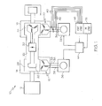
- FIG. 1 is a schematic of an embodiment of a starter generator
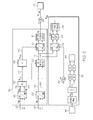
- FIG. 2 is a schematic of an embodiment of a system for determining and tracking position of a rotor.
- FIG. 1 Shown in FIG. 1 is a schematic of a dynamoelectric machine, in this case a starter generator 10, connected to a prime mover, for example, an aircraft engine 12.
- the starter generator 10 is of a brushless wound field type including a main machine 14 having a main stator 16.
- the main stator 16 of FIG. 1 is a three-phase alternating current (AC) stator, but it is to be appreciated that the main stator 16 may have other numbers of phases which number two or more.
- the starter generator 10 further includes an exciter portion 18 having an exciter stator 20.
- the exciter stator 20 of FIG. 1 is a three-phase alternating current (AC) stator, but it is to be appreciated that the exciter stator 20 may have other numbers of phases which number two or more.
- the starter generator 10 further includes a generator rotor 22 which includes a multiphase AC exciter armature 24 interactive with the exciter stator 20 and a main machine rotor 26 interactive with the main stator 16.
- the main machine rotor 26 includes a direct current (DC) field winding 28, and is connected to the exciter armature 24 via a rectifier 30, which rectifies AC current induced in the exciter armature 24 to supply DC that energizes the main rotor field winding 28.
- the rectifier 30 may be a full or half-wave rectifier 30.
- An AC power source 32 supplies an AC excitation to the exciter stator 20 via exciter input lines 34.
- the AC power source 32 may be an inverter, AC power from an aircraft AC power bus, or any other suitable source of AC power.
- a main inverter 36 supplies an AC drive signal to the main stator 18 via main input lines 38.
- the position of the generator rotor 22 is determined and tracked via a double injection sensorless (DIS) logic described herein, using both injection of a main stator stimulus, S M , into the main stator 16 in the form of either voltage or current, and injection of an exciter stator stimulus, S E , into the exciter stator 20 in the form of either voltage or current.
- the exciter stator stimulus is injected into or applied to the exciter stator 20 at the initiation of the start sequence from the AC power source 32 to generate a field to initiate rotation of the generator rotor 22. This injection of the exciter stator stimulus is initiated by a starter control system 44.
- the starter control system 44 in the first few instants of the start sequence, directs the main inverter 36 to similarly inject the main stator stimulus, a carrier voltage or current, into the main stator 16.
- the main stator stimulus applied is not great enough to power the main rotor 26, but only to be utilized to determine the true or absolute position of the generator rotor 22.
- a three-phase exciter stator response, R Eabc , and a three phase exciter stator stimulus, S Eabc are sensed by sensors 40 and 42 respectively, at the exciter input lines 34 and include response harmonics related to the main stator stimulus applied to the main stator 16.
- R Eabc and S Eabc are input into an exciter stator harmonic tracking (ESHT) logic 46.
- ESHT exciter stator harmonic tracking
- a Clark transformation 48 receives the sensed exciter stator stimulus, S Eabc , and transforms it into S E ⁇ and S E ⁇ .
- a phase lock loop (PLL) 50 receives S E ⁇ and S E ⁇ on signal lines 52 and 54, and outputs an estimated exciter stator stimulus rotating waveform angle, ⁇ e1p .
- a harmonic multiplier 56 tuned to the -5 th harmonic of the exciter frequency, receives the ⁇ e1p signal on signal path 58 and outputs the -5 th harmonic of ⁇ e1p , or ⁇ e5n , along signal path 60.
- the three-phase exciter stator response, R Eabc is transformed via a Clarke transformation 62 into ⁇ -axis and ⁇ -axis signals, R E ⁇ and R E ⁇ and outputs the signals along signal paths 64 and 66.
- ⁇ e1p and R E ⁇ and R E ⁇ are input into an f e1p notch filter 68, for example, to filter out exciter fundamental frequency response harmonics.
- a Park transformation 70 receives the filtered R E ⁇ and R E ⁇ via signal paths 72 and 74 and using the angle of the -5 th harmonic of the exciter stator stimulus, S E , ⁇ e5n , transforms R E ⁇ and R E ⁇ into a d-axis signal R Ede5n and a q-axis signal R Eqe5n , where the d-q reference frame is a rotating reference frame for the exciter space vector harmonic which rotates at the -5 th harmonic of the exciter stator stimulus, S E .
- R Ede5n and R Eqe5n are utilized in an estimation of rotor position, ⁇ r , via, for example a PLL 76.
- the main stator stimulus, S M , applied to the main stator 16 is provided by a double injection sensorless (DIS) calibration logic 78.
- the DIS logic 78 uses the main stator stimulus angle ⁇ c and adds ⁇ c to ⁇ e1p at an input summer 80.
- This summed angle, ⁇ c+e1p is utilized as a transformation angle to transform post-notch filter R E ⁇ and R E ⁇ to R Edecs and R Eqecs , at Park transformation 82, the transformation resulting in responses that contain true or actual rotor angle information.
- R Edecs and R Eqecs are filtered to remove unwanted high frequency harmonic content by being passed through a low pass filter 84, for example.
- the resulting signals are utilized to estimate the true rotor position of the main machine at estimation block 86.
- the estimation may comprise using an arctan function, a rotating vector PLL, a rotor position estimator, or any number of other techniques known in the art.
- the ESHT logic 46 determines one of several possible positions of the starter generator rotor 22.
- the estimated rotor position output by the ESHT logic 46, or ⁇ r is offset by some angular amount from the true position of the starter generator rotor 22.
- the true position of the starter generator rotor 22 determined by the DIS logic 78, or ⁇ DIS is used in combination with ⁇ r to calibrate the ESHT logic 46 via a calibration routine.
- a calibration offset, ⁇ real is then fed back into the starter control system 44 for continued use by the ESHT logic 46 throughout the start sequence.
- operation of the DIS logic 78 is stopped.
- the DIS logic 78 and the ESHT logic 46, as well as other calculations described herein may be implemented via processing circuitry, firmware such as Field Programmable Gate Arrays (FPGA), or software for digital signal processor (DSP).
- FPGA Field Programmable Gate Arrays
- DSP digital signal processor
Landscapes
- Engineering & Computer Science (AREA)
- Power Engineering (AREA)
- Control Of Eletrric Generators (AREA)
- Control Of Motors That Do Not Use Commutators (AREA)
- Synchronous Machinery (AREA)
Abstract
Description
- The subject matter disclosed herein relates to dynamoelectric machines. More specifically, the subject matter disclosed herein relates to rotor position determination for wound field synchronous machines.
- A multi-phase alternating current (AC) dynamoelectric machine can be used as a motor or as a generator. In aircraft applications in particular, it is desirable to use such a machine for both electrical power generation and as a starter motor to promote weight and space savings on the aircraft. When used as a starter, the position of the rotor of the dynamoelectric machine must be determined in order to properly orient the stator current rotating 3-phase waveform relative to the magnetic north pole of the rotor. Orienting the stator current waveform relative to the rotor position is necessary for motor operation and proper orientation results in an optimum amount of torque being produced by the dynamoelectric machine.
- Since a mechanical rotor position sensor can be costly and lacking in reliability, it is desired to determine the rotor position without the use of such a mechanical position sensor. In general, there are two categories of sensorless rotor position determinations. The first is a back EMF based method, which is relatively easy to implement and usually works well at high angular rotor velocity, but is less reliable at low rotor velocity and doesn't work at all below some threshold speed or at standstill. The second is a signal injection method, which is required below some threshold angular rotor velocity or at standstill. Systems that utilize the signal injection method, however, are subject to a rotor position error of up to 180 degrees because the system cannot recognize which of a number of possible rotor positions it has locked on to or is tracking.
- A carrier injection sensorless (CIS) logic has been developed which successfully determines which of the possible rotor positions that the system is tracking providing an absolute or true rotor position. The determination of true rotor position involves two separate CIS logic blocks, the first of which interrogates the exciter stator to lock on to and track the rotor position by measuring and demodulating the current harmonics contained in the 3-phase exciter of the machine and the second which interrogates the main machine through its stator to determine which of the possible rotor positions the exciter based CIS logic block has locked on to and is tracking. This result is used to calibrate the first logic block to provide a true or absolute rotor position. The second CIS logic block has inherent north/south pole indeterminacy and determines main machine positive from negative poles by, for example, saturating the main machine rotor or using the rectification in the rotating rectifier of the machine in a secondary logic. Thus, both techniques require a two-step process whereby the primary CIS logic block locks on to a preferred position as in the exciter CIS or to a pole as in the main machine stator CIS, and the secondary CIS logic block determines which of the possible rotor positions the primary CIS has locked on to thereby providing a correction or calibration to the primary CIS logic block. The double two-step process requires significant logic complexity. Further, using rectification to provide the secondary current harmonic increases the electrical stress on the rotating rectifier diodes thereby reducing their reliability. Additionally, the main stator carrier currents required to induce saturation in the main machine may be so large at to significantly upsize the current sourcing requirements of the main machine AC power supply.
- In one embodiment, a rotor position determination and tracking system for a dynamoelectric machine includes a first AC power supply to inject a main stator stimulus into a main stator of the dynamoelectric machine. A second AC power supply injects an exciter stator stimulus into an exciter stator of the dynamoelectric machine via a plurality of exciter input lines. A plurality of current sensors and voltage sensors are located at the exciter input lines to sense current and voltage thereat. A first control logic receives the sensed current and voltage and outputs an estimated rotor position. A second control logic receives an estimated exciter stator stimulus rotating wave form angle and filtered sensed exciter stator response signals from the first control logic and utilizes a known main stator carrier frequency to determine the rotor position. The rotor position is input into the first control logic to calibrate the first control logic for further tracking of the rotor position.
- In another embodiment, a method of rotor position determination and tracking for a dynamoelectric machine includes injecting a main stator stimulus into a main stator of the dynamoelectric machine and injecting an exciter stator stimulus into an exciter stator of the dynamoelectric machine via a plurality of exciter input lines. An exciter current and an exciter voltage are sensed via a plurality of current sensors and voltage sensors disposed at the exciter input lines. An estimated rotor position is determined via a first control logic utilizing the sensed exciter current and exciter voltage. A rotor position is determined via a second control logic utilizing an estimated exciter stator stimulus rotating wave form angle and filtered exciter stator response signals from the first control logic together with a known main stator carrier frequency. The rotor position is input into the first control logic to calibrate the first control logic for further tracking of the rotor position.
- These and other advantages and features will become more apparent from the following description taken in conjunction with the drawings.
- The subject matter, which is regarded as the invention, is particularly pointed out and distinctly claimed in the claims at the conclusion of the specification. The foregoing and other features, and advantages of the invention are apparent from the following detailed description taken in conjunction with the accompanying drawings in which:
-
FIG. 1 is a schematic of an embodiment of a starter generator; and -
FIG. 2 is a schematic of an embodiment of a system for determining and tracking position of a rotor. - The detailed description explains embodiments of the invention, together with advantages and features, by way of example with reference to the drawings.
- Shown in
FIG. 1 is a schematic of a dynamoelectric machine, in this case astarter generator 10, connected to a prime mover, for example, anaircraft engine 12. Thestarter generator 10 is of a brushless wound field type including amain machine 14 having amain stator 16. Themain stator 16 ofFIG. 1 is a three-phase alternating current (AC) stator, but it is to be appreciated that themain stator 16 may have other numbers of phases which number two or more. Thestarter generator 10 further includes anexciter portion 18 having anexciter stator 20. Theexciter stator 20 ofFIG. 1 is a three-phase alternating current (AC) stator, but it is to be appreciated that theexciter stator 20 may have other numbers of phases which number two or more. Thestarter generator 10 further includes agenerator rotor 22 which includes a multiphaseAC exciter armature 24 interactive with theexciter stator 20 and amain machine rotor 26 interactive with themain stator 16. Themain machine rotor 26 includes a direct current (DC) field winding 28, and is connected to theexciter armature 24 via arectifier 30, which rectifies AC current induced in theexciter armature 24 to supply DC that energizes the main rotor field winding 28. Therectifier 30 may be a full or half-wave rectifier 30. AnAC power source 32 supplies an AC excitation to the exciterstator 20 via exciterinput lines 34. TheAC power source 32 may be an inverter, AC power from an aircraft AC power bus, or any other suitable source of AC power. Similarly, amain inverter 36 supplies an AC drive signal to themain stator 18 viamain input lines 38. - The position of the
generator rotor 22 is determined and tracked via a double injection sensorless (DIS) logic described herein, using both injection of a main stator stimulus, SM, into themain stator 16 in the form of either voltage or current, and injection of an exciter stator stimulus, SE, into theexciter stator 20 in the form of either voltage or current. The exciter stator stimulus is injected into or applied to theexciter stator 20 at the initiation of the start sequence from theAC power source 32 to generate a field to initiate rotation of thegenerator rotor 22. This injection of the exciter stator stimulus is initiated by astarter control system 44. Thestarter control system 44, in the first few instants of the start sequence, directs themain inverter 36 to similarly inject the main stator stimulus, a carrier voltage or current, into themain stator 16. The main stator stimulus applied is not great enough to power themain rotor 26, but only to be utilized to determine the true or absolute position of thegenerator rotor 22. - A three-phase exciter stator response, REabc, and a three phase exciter stator stimulus, SEabc, are sensed by
sensors exciter input lines 34 and include response harmonics related to the main stator stimulus applied to themain stator 16. Referring now toFIG. 2 , REabc and SEabc are input into an exciter stator harmonic tracking (ESHT)logic 46. AClark transformation 48 receives the sensed exciter stator stimulus, SEabc, and transforms it into SEα and SEβ. A phase lock loop (PLL) 50 receives SEα and SEβ onsignal lines harmonic multiplier 56, tuned to the -5th harmonic of the exciter frequency, receives the θe1p signal onsignal path 58 and outputs the -5th harmonic of θe1p, or θe5n, alongsignal path 60. - The three-phase exciter stator response, REabc, is transformed via a Clarke
transformation 62 into α-axis and β-axis signals, REα and REβ and outputs the signals alongsignal paths Park transformation 70 receives the filtered REα and REβ viasignal paths PLL 76. - The main stator stimulus, SM, applied to the
main stator 16 is provided by a double injection sensorless (DIS)calibration logic 78. The DISlogic 78 uses the main stator stimulus angle θc and adds θc to θe1p at aninput summer 80. This summed angle, θc+e1p, is utilized as a transformation angle to transform post-notch filter REα and REβ to REdecs and REqecs, atPark transformation 82, the transformation resulting in responses that contain true or actual rotor angle information. REdecs and REqecs are filtered to remove unwanted high frequency harmonic content by being passed through alow pass filter 84, for example. The resulting signals are utilized to estimate the true rotor position of the main machine atestimation block 86. The estimation may comprise using an arctan function, a rotating vector PLL, a rotor position estimator, or any number of other techniques known in the art. - During initial position estimation of the
starter generator rotor 22, theESHT logic 46 determines one of several possible positions of thestarter generator rotor 22. The estimated rotor position output by theESHT logic 46, or θr, is offset by some angular amount from the true position of thestarter generator rotor 22. The true position of thestarter generator rotor 22 determined by theDIS logic 78, or θDIS, is used in combination with θr to calibrate theESHT logic 46 via a calibration routine. A calibration offset, θreal, is then fed back into thestarter control system 44 for continued use by theESHT logic 46 throughout the start sequence. At this point, operation of theDIS logic 78 is stopped. It is to be appreciated that theDIS logic 78 and theESHT logic 46, as well as other calculations described herein may be implemented via processing circuitry, firmware such as Field Programmable Gate Arrays (FPGA), or software for digital signal processor (DSP). - While the invention has been described in detail in connection with only a limited number of embodiments, it should be readily understood that the invention is not limited to such disclosed embodiments. Rather, the invention can be modified to incorporate any number of variations, alterations, substitutions or equivalent arrangements not heretofore described, but which are commensurate with the scope of the invention. Additionally, while various embodiments of the invention have been described, it is to be understood that aspects of the invention may include only some of the described embodiments. Accordingly, the invention is not to be seen as limited by the foregoing description, but is only limited by the scope of the appended claims.
Claims (15)
- A rotor position determination and tracking system for a dynamoelectric machine (10) comprising:a first AC power supply (36) to inject a main stator stimulus into a main stator (16) of the dynamoelectric machine;a second AC power supply (32) to inject an exciter stator stimulus into an exciter stator (20) of the dynamoelectric machine via a plurality of exciter input lines (34);a plurality of current sensors and voltage sensors disposed at the exciter input lines to sense current and voltage thereat;a first control logic (46) that receives the sensed current and voltage and outputs an estimated rotor position (θr); anda second control logic (78) that receives an estimated exciter stator stimulus rotating wave form angle (θe1p) and filtered sensed exciter stator response signals from the first control logic and utilizes a known main stator carrier frequency (ωc) to determine the rotor position (θe1b), the rotor position being input into the first control logic (46) to calibrate the first control logic for further tracking of the rotor position.
- The system of Claim 1, wherein the first control logic includes a notch filter (68) to filter the sensed exciter field response signals.
- The system of Claim 1 or 2, wherein the first control logic further includes a phase lock loop (50) operating on sensed exciter stator stimulus signals to determine the estimated exciter stator stimulus rotating wave form angle (θe1p)·
- The system of Claim 3, further comprising a Clark transformation (48) to transform the sensed exciter stator stimulus signals into α and β coordinate signals prior to operation of the phase lock loop (50).
- The system of Claim 1, 2, 3 or 4, wherein the first control logic (46) further includes a harmonic multiplier (56) to multiply the estimated exciter stator stimulus rotating wave form angle and output a selected harmonic thereof.
- The system of Claim 5, wherein the first control logic (46) further includes a first Park transformation (70) utilizing the selected harmonic to transform the filtered exciter field response signals into a rotating reference frame of the selected harmonic.
- The system of any preceding Claim, wherein the second control logic (78) includes an input summer (80) to add the estimated exciter stator stimulus rotating wave form angle and a main stator stimulus angle (θc) determined from the main stator stimulus frequency (ωc); preferably wherein the second control logic (78) further includes a second Park transformation (82) to transform the filtered sensed exciter stator response signals to a rotating reference frame utilizing the sum of the estimated exciter stator stimulus rotating wave form angle and the main stator stimulus angle.
- A method of rotor position determination and tracking for a dynamoelectric machine comprising:injecting a main stator stimulus into a main stator of the dynamoelectric machine;injecting an exciter stator stimulus into an exciter stator of the dynamoelectric machine via a plurality of exciter input lines;sensing an exciter current and an exciter voltage via a plurality of current sensors and voltage sensors disposed at the exciter input lines;determining an estimated rotor position (θr) via a first control logic utilizing the sensed exciter current and exciter voltage;determining a rotor position via a second control logic utilizing an estimated exciter stator stimulus rotating wave form angle and filtered exciter stator response signals from the first control logic together with a known main stator carrier frequency; andinputting the rotor position into the first control logic to calibrate the first control logic for further tracking of the rotor position.
- The method of Claim 8, further comprising filtering the exciter stator response signals in the first control logic via a notch filter.
- The method of Claim 8 or 9, further comprising determining the estimated exciter stator stimulus rotating wave form angle in the first control logic via a phase lock loop (50).
- The method of Claim 10, further comprising transforming sensed main stator stimulus signals into α and β coordinate signals prior to operation of the phase lock loop; preferably wherein the transformation is accomplished via a Clark transformation (48).
- The method of Claim 8, 9, 10 or 11, further comprising:multiplying the estimated exciter stator stimulus rotating wave form angle; andoutputting a selected harmonic thereof in the first control logic.
- The method of Claim 12, further comprising utilizing the selected harmonic to transform (70) the filtered exciter stator response signals into a rotating reference frame of the selected harmonic in the first control logic.
- The method of any of claims 8 to 13, further comprising summing (80) the estimated exciter stator stimulus rotating wave form angle (θe1p) and a main stator stimulus angle (θc) determined from the main stator stimulus frequency (ωc) in the second control logic.
- The method of Claim 16, further comprising transforming (82) the filtered exciter stator response signals to a rotating reference frame utilizing the sum of the estimated exciter stator stimulus rotating wave form angle and the main stator stimulus angle; preferably wherein the transformation is accomplished via a Park transformation.
Applications Claiming Priority (1)
| Application Number | Priority Date | Filing Date | Title |
|---|---|---|---|
| US13/361,520 US9374027B2 (en) | 2012-01-30 | 2012-01-30 | Sensorless rotor position determination for a wound field synchronous machine |
Publications (3)
| Publication Number | Publication Date |
|---|---|
| EP2621081A2 true EP2621081A2 (en) | 2013-07-31 |
| EP2621081A3 EP2621081A3 (en) | 2017-06-28 |
| EP2621081B1 EP2621081B1 (en) | 2020-09-09 |
Family
ID=47665957
Family Applications (1)
| Application Number | Title | Priority Date | Filing Date |
|---|---|---|---|
| EP13153358.0A Active EP2621081B1 (en) | 2012-01-30 | 2013-01-30 | Sensorless rotor position determination for a wound field synchronous machine |
Country Status (2)
| Country | Link |
|---|---|
| US (1) | US9374027B2 (en) |
| EP (1) | EP2621081B1 (en) |
Cited By (1)
| Publication number | Priority date | Publication date | Assignee | Title |
|---|---|---|---|---|
| EP3082250A1 (en) * | 2015-04-14 | 2016-10-19 | Hamilton Sundstrand Corporation | Sensorless control of a dc synchronous machine |
Families Citing this family (3)
| Publication number | Priority date | Publication date | Assignee | Title |
|---|---|---|---|---|
| US9979339B2 (en) | 2015-12-14 | 2018-05-22 | Rolls-Royce North American Technologies Inc. | Synchronous electric power distribution startup system |
| US10454404B2 (en) * | 2017-11-22 | 2019-10-22 | The Boeing Company | Generator field exciter system |
| CN116191957B (en) * | 2022-12-22 | 2025-12-19 | 西北工业大学 | Multistage motor initial position estimation method based on excitation signal sinusoidal modulation |
Family Cites Families (5)
| Publication number | Priority date | Publication date | Assignee | Title |
|---|---|---|---|---|
| US7034497B2 (en) * | 2004-09-22 | 2006-04-25 | Hamilton Sundstrand Corporation | Carrier injection sensorless control of aircraft variable frequency wound field synchronous starter/generators |
| US7132816B1 (en) * | 2006-02-20 | 2006-11-07 | Hamilton Sundstrand Corporation | Brushless wound field synchronous machine rotor position tracking with exciter stator current harmonic tracking |
| US7508086B2 (en) * | 2006-03-24 | 2009-03-24 | General Electric Company | Aircraft engine starter/generator and controller |
| US7583046B2 (en) * | 2007-06-20 | 2009-09-01 | Hamilton Sundstrand Corporation | Rotor position detection at standstill and low speeds using a low power permanent magnet machine |
| US8362728B2 (en) * | 2010-09-15 | 2013-01-29 | Hamilton Sundstrand Corporation | Rotor position detection at standstill and low speeds using a PMG to operate a wound field synchronous machine |
-
2012
- 2012-01-30 US US13/361,520 patent/US9374027B2/en active Active
-
2013
- 2013-01-30 EP EP13153358.0A patent/EP2621081B1/en active Active
Non-Patent Citations (1)
| Title |
|---|
| None |
Cited By (3)
| Publication number | Priority date | Publication date | Assignee | Title |
|---|---|---|---|---|
| EP3082250A1 (en) * | 2015-04-14 | 2016-10-19 | Hamilton Sundstrand Corporation | Sensorless control of a dc synchronous machine |
| US10033252B2 (en) | 2015-04-14 | 2018-07-24 | Hamilton Sundstrand Corporation | Sensorless control of a DC synchronous machine |
| US10566880B2 (en) | 2015-04-14 | 2020-02-18 | Hamilton Sundstrand Corporation | Sensorless control of a DC synchronous machine |
Also Published As
| Publication number | Publication date |
|---|---|
| US20130193888A1 (en) | 2013-08-01 |
| US9374027B2 (en) | 2016-06-21 |
| EP2621081B1 (en) | 2020-09-09 |
| EP2621081A3 (en) | 2017-06-28 |
Similar Documents
| Publication | Publication Date | Title |
|---|---|---|
| Wei et al. | An integrated method for three-phase AC excitation and high-frequency voltage signal injection for sensorless starting of aircraft starter/generator | |
| US7034497B2 (en) | Carrier injection sensorless control of aircraft variable frequency wound field synchronous starter/generators | |
| EP2061147B1 (en) | Initial rotor position detection and start-up system for a dynamoelectric machine | |
| JP5324159B2 (en) | Motor control device | |
| Seo et al. | An improved rotating restart method for a sensorless permanent magnet synchronous motor drive system using repetitive zero voltage vectors | |
| US8884566B2 (en) | Method of position sensorless control of an electrical machine | |
| US8362728B2 (en) | Rotor position detection at standstill and low speeds using a PMG to operate a wound field synchronous machine | |
| JP5543388B2 (en) | Control device for permanent magnet synchronous motor | |
| JP2003052193A (en) | Method for detecting magnetic pole position of motor, magnetic pole position detecting device, and motor control device using the same | |
| US7132816B1 (en) | Brushless wound field synchronous machine rotor position tracking with exciter stator current harmonic tracking | |
| CN102362424A (en) | Control device and control method for rotating electric machine | |
| Ishida et al. | Steady-state characteristics of a torque and speed control system of an induction motor utilizing rotor slot harmonics for slip frequency sensing | |
| Chen et al. | Self-sensing control of permanent-magnet synchronous machines with multiple saliencies using pulse-voltage-injection | |
| JP2004032944A (en) | Control device for synchronous motor and synchronous motor | |
| US7583046B2 (en) | Rotor position detection at standstill and low speeds using a low power permanent magnet machine | |
| EP2621081B1 (en) | Sensorless rotor position determination for a wound field synchronous machine | |
| CN105871276B (en) | The three-level formula motor rotor position estimation method of salient pole nature variation | |
| JPWO2020115859A1 (en) | Rotating machine control device and electric vehicle control device | |
| Boldea et al. | “Active flux” orientation vector sensorless control of IPMSM | |
| JP4397889B2 (en) | Magnetic pole position estimation device for synchronous motor | |
| CN113783493B (en) | A method for estimating the rotor initial position of a three-stage synchronous starter generator | |
| Lashkevich et al. | Investigation of self-sensing rotor position estimation methods for synchronous homopolar motor in traction applications | |
| Mao et al. | Initial rotor position estimation for brushless synchronous starter/generators | |
| JP4153619B2 (en) | Electric motor control device | |
| Montero et al. | Sensorless saliency-based control of dual induction machines under dynamic load imbalances using three current sensors |
Legal Events
| Date | Code | Title | Description |
|---|---|---|---|
| PUAI | Public reference made under article 153(3) epc to a published international application that has entered the european phase |
Free format text: ORIGINAL CODE: 0009012 |
|
| AK | Designated contracting states |
Kind code of ref document: A2 Designated state(s): AL AT BE BG CH CY CZ DE DK EE ES FI FR GB GR HR HU IE IS IT LI LT LU LV MC MK MT NL NO PL PT RO RS SE SI SK SM TR |
|
| AX | Request for extension of the european patent |
Extension state: BA ME |
|
| PUAL | Search report despatched |
Free format text: ORIGINAL CODE: 0009013 |
|
| AK | Designated contracting states |
Kind code of ref document: A3 Designated state(s): AL AT BE BG CH CY CZ DE DK EE ES FI FR GB GR HR HU IE IS IT LI LT LU LV MC MK MT NL NO PL PT RO RS SE SI SK SM TR |
|
| AX | Request for extension of the european patent |
Extension state: BA ME |
|
| RIC1 | Information provided on ipc code assigned before grant |
Ipc: H02P 6/18 20160101AFI20170522BHEP |
|
| STAA | Information on the status of an ep patent application or granted ep patent |
Free format text: STATUS: REQUEST FOR EXAMINATION WAS MADE |
|
| 17P | Request for examination filed |
Effective date: 20171222 |
|
| RBV | Designated contracting states (corrected) |
Designated state(s): AL AT BE BG CH CY CZ DE DK EE ES FI FR GB GR HR HU IE IS IT LI LT LU LV MC MK MT NL NO PL PT RO RS SE SI SK SM TR |
|
| REG | Reference to a national code |
Ref country code: DE Ref legal event code: R079 Ref document number: 602013072307 Country of ref document: DE Free format text: PREVIOUS MAIN CLASS: H02P0006180000 Ipc: H02P0021180000 |
|
| GRAP | Despatch of communication of intention to grant a patent |
Free format text: ORIGINAL CODE: EPIDOSNIGR1 |
|
| STAA | Information on the status of an ep patent application or granted ep patent |
Free format text: STATUS: GRANT OF PATENT IS INTENDED |
|
| RIC1 | Information provided on ipc code assigned before grant |
Ipc: H02P 6/18 20160101ALI20200402BHEP Ipc: H02P 21/18 20160101AFI20200402BHEP |
|
| INTG | Intention to grant announced |
Effective date: 20200416 |
|
| RIN1 | Information on inventor provided before grant (corrected) |
Inventor name: MARKUNAS, ALBERT L. |
|
| RAP1 | Party data changed (applicant data changed or rights of an application transferred) |
Owner name: HAMILTON SUNDSTRAND CORPORATION |
|
| GRAS | Grant fee paid |
Free format text: ORIGINAL CODE: EPIDOSNIGR3 |
|
| GRAA | (expected) grant |
Free format text: ORIGINAL CODE: 0009210 |
|
| STAA | Information on the status of an ep patent application or granted ep patent |
Free format text: STATUS: THE PATENT HAS BEEN GRANTED |
|
| AK | Designated contracting states |
Kind code of ref document: B1 Designated state(s): AL AT BE BG CH CY CZ DE DK EE ES FI FR GB GR HR HU IE IS IT LI LT LU LV MC MK MT NL NO PL PT RO RS SE SI SK SM TR |
|
| REG | Reference to a national code |
Ref country code: GB Ref legal event code: FG4D |
|
| REG | Reference to a national code |
Ref country code: AT Ref legal event code: REF Ref document number: 1312815 Country of ref document: AT Kind code of ref document: T Effective date: 20200915 Ref country code: CH Ref legal event code: EP |
|
| REG | Reference to a national code |
Ref country code: DE Ref legal event code: R096 Ref document number: 602013072307 Country of ref document: DE |
|
| REG | Reference to a national code |
Ref country code: IE Ref legal event code: FG4D |
|
| REG | Reference to a national code |
Ref country code: LT Ref legal event code: MG4D |
|
| PG25 | Lapsed in a contracting state [announced via postgrant information from national office to epo] |
Ref country code: GR Free format text: LAPSE BECAUSE OF FAILURE TO SUBMIT A TRANSLATION OF THE DESCRIPTION OR TO PAY THE FEE WITHIN THE PRESCRIBED TIME-LIMIT Effective date: 20201210 Ref country code: NO Free format text: LAPSE BECAUSE OF FAILURE TO SUBMIT A TRANSLATION OF THE DESCRIPTION OR TO PAY THE FEE WITHIN THE PRESCRIBED TIME-LIMIT Effective date: 20201209 Ref country code: LT Free format text: LAPSE BECAUSE OF FAILURE TO SUBMIT A TRANSLATION OF THE DESCRIPTION OR TO PAY THE FEE WITHIN THE PRESCRIBED TIME-LIMIT Effective date: 20200909 Ref country code: HR Free format text: LAPSE BECAUSE OF FAILURE TO SUBMIT A TRANSLATION OF THE DESCRIPTION OR TO PAY THE FEE WITHIN THE PRESCRIBED TIME-LIMIT Effective date: 20200909 Ref country code: BG Free format text: LAPSE BECAUSE OF FAILURE TO SUBMIT A TRANSLATION OF THE DESCRIPTION OR TO PAY THE FEE WITHIN THE PRESCRIBED TIME-LIMIT Effective date: 20201209 Ref country code: SE Free format text: LAPSE BECAUSE OF FAILURE TO SUBMIT A TRANSLATION OF THE DESCRIPTION OR TO PAY THE FEE WITHIN THE PRESCRIBED TIME-LIMIT Effective date: 20200909 Ref country code: FI Free format text: LAPSE BECAUSE OF FAILURE TO SUBMIT A TRANSLATION OF THE DESCRIPTION OR TO PAY THE FEE WITHIN THE PRESCRIBED TIME-LIMIT Effective date: 20200909 |
|
| REG | Reference to a national code |
Ref country code: AT Ref legal event code: MK05 Ref document number: 1312815 Country of ref document: AT Kind code of ref document: T Effective date: 20200909 |
|
| REG | Reference to a national code |
Ref country code: NL Ref legal event code: MP Effective date: 20200909 |
|
| PG25 | Lapsed in a contracting state [announced via postgrant information from national office to epo] |
Ref country code: RS Free format text: LAPSE BECAUSE OF FAILURE TO SUBMIT A TRANSLATION OF THE DESCRIPTION OR TO PAY THE FEE WITHIN THE PRESCRIBED TIME-LIMIT Effective date: 20200909 Ref country code: LV Free format text: LAPSE BECAUSE OF FAILURE TO SUBMIT A TRANSLATION OF THE DESCRIPTION OR TO PAY THE FEE WITHIN THE PRESCRIBED TIME-LIMIT Effective date: 20200909 Ref country code: PL Free format text: LAPSE BECAUSE OF FAILURE TO SUBMIT A TRANSLATION OF THE DESCRIPTION OR TO PAY THE FEE WITHIN THE PRESCRIBED TIME-LIMIT Effective date: 20200909 |
|
| PG25 | Lapsed in a contracting state [announced via postgrant information from national office to epo] |
Ref country code: SM Free format text: LAPSE BECAUSE OF FAILURE TO SUBMIT A TRANSLATION OF THE DESCRIPTION OR TO PAY THE FEE WITHIN THE PRESCRIBED TIME-LIMIT Effective date: 20200909 Ref country code: RO Free format text: LAPSE BECAUSE OF FAILURE TO SUBMIT A TRANSLATION OF THE DESCRIPTION OR TO PAY THE FEE WITHIN THE PRESCRIBED TIME-LIMIT Effective date: 20200909 Ref country code: NL Free format text: LAPSE BECAUSE OF FAILURE TO SUBMIT A TRANSLATION OF THE DESCRIPTION OR TO PAY THE FEE WITHIN THE PRESCRIBED TIME-LIMIT Effective date: 20200909 Ref country code: PT Free format text: LAPSE BECAUSE OF FAILURE TO SUBMIT A TRANSLATION OF THE DESCRIPTION OR TO PAY THE FEE WITHIN THE PRESCRIBED TIME-LIMIT Effective date: 20210111 Ref country code: CZ Free format text: LAPSE BECAUSE OF FAILURE TO SUBMIT A TRANSLATION OF THE DESCRIPTION OR TO PAY THE FEE WITHIN THE PRESCRIBED TIME-LIMIT Effective date: 20200909 Ref country code: EE Free format text: LAPSE BECAUSE OF FAILURE TO SUBMIT A TRANSLATION OF THE DESCRIPTION OR TO PAY THE FEE WITHIN THE PRESCRIBED TIME-LIMIT Effective date: 20200909 |
|
| RAP4 | Party data changed (patent owner data changed or rights of a patent transferred) |
Owner name: HAMILTON SUNDSTRAND CORPORATION |
|
| PG25 | Lapsed in a contracting state [announced via postgrant information from national office to epo] |
Ref country code: IS Free format text: LAPSE BECAUSE OF FAILURE TO SUBMIT A TRANSLATION OF THE DESCRIPTION OR TO PAY THE FEE WITHIN THE PRESCRIBED TIME-LIMIT Effective date: 20210109 Ref country code: AT Free format text: LAPSE BECAUSE OF FAILURE TO SUBMIT A TRANSLATION OF THE DESCRIPTION OR TO PAY THE FEE WITHIN THE PRESCRIBED TIME-LIMIT Effective date: 20200909 Ref country code: AL Free format text: LAPSE BECAUSE OF FAILURE TO SUBMIT A TRANSLATION OF THE DESCRIPTION OR TO PAY THE FEE WITHIN THE PRESCRIBED TIME-LIMIT Effective date: 20200909 Ref country code: ES Free format text: LAPSE BECAUSE OF FAILURE TO SUBMIT A TRANSLATION OF THE DESCRIPTION OR TO PAY THE FEE WITHIN THE PRESCRIBED TIME-LIMIT Effective date: 20200909 |
|
| REG | Reference to a national code |
Ref country code: DE Ref legal event code: R097 Ref document number: 602013072307 Country of ref document: DE |
|
| PG25 | Lapsed in a contracting state [announced via postgrant information from national office to epo] |
Ref country code: SK Free format text: LAPSE BECAUSE OF FAILURE TO SUBMIT A TRANSLATION OF THE DESCRIPTION OR TO PAY THE FEE WITHIN THE PRESCRIBED TIME-LIMIT Effective date: 20200909 |
|
| PLBE | No opposition filed within time limit |
Free format text: ORIGINAL CODE: 0009261 |
|
| STAA | Information on the status of an ep patent application or granted ep patent |
Free format text: STATUS: NO OPPOSITION FILED WITHIN TIME LIMIT |
|
| 26N | No opposition filed |
Effective date: 20210610 |
|
| PG25 | Lapsed in a contracting state [announced via postgrant information from national office to epo] |
Ref country code: SI Free format text: LAPSE BECAUSE OF FAILURE TO SUBMIT A TRANSLATION OF THE DESCRIPTION OR TO PAY THE FEE WITHIN THE PRESCRIBED TIME-LIMIT Effective date: 20200909 Ref country code: DK Free format text: LAPSE BECAUSE OF FAILURE TO SUBMIT A TRANSLATION OF THE DESCRIPTION OR TO PAY THE FEE WITHIN THE PRESCRIBED TIME-LIMIT Effective date: 20200909 Ref country code: MC Free format text: LAPSE BECAUSE OF FAILURE TO SUBMIT A TRANSLATION OF THE DESCRIPTION OR TO PAY THE FEE WITHIN THE PRESCRIBED TIME-LIMIT Effective date: 20200909 |
|
| REG | Reference to a national code |
Ref country code: CH Ref legal event code: PL |
|
| PG25 | Lapsed in a contracting state [announced via postgrant information from national office to epo] |
Ref country code: LU Free format text: LAPSE BECAUSE OF NON-PAYMENT OF DUE FEES Effective date: 20210130 |
|
| REG | Reference to a national code |
Ref country code: BE Ref legal event code: MM Effective date: 20210131 |
|
| PG25 | Lapsed in a contracting state [announced via postgrant information from national office to epo] |
Ref country code: IT Free format text: LAPSE BECAUSE OF FAILURE TO SUBMIT A TRANSLATION OF THE DESCRIPTION OR TO PAY THE FEE WITHIN THE PRESCRIBED TIME-LIMIT Effective date: 20200909 |
|
| PG25 | Lapsed in a contracting state [announced via postgrant information from national office to epo] |
Ref country code: LI Free format text: LAPSE BECAUSE OF NON-PAYMENT OF DUE FEES Effective date: 20210131 Ref country code: CH Free format text: LAPSE BECAUSE OF NON-PAYMENT OF DUE FEES Effective date: 20210131 |
|
| PG25 | Lapsed in a contracting state [announced via postgrant information from national office to epo] |
Ref country code: IE Free format text: LAPSE BECAUSE OF NON-PAYMENT OF DUE FEES Effective date: 20210130 |
|
| PG25 | Lapsed in a contracting state [announced via postgrant information from national office to epo] |
Ref country code: BE Free format text: LAPSE BECAUSE OF NON-PAYMENT OF DUE FEES Effective date: 20210131 |
|
| PG25 | Lapsed in a contracting state [announced via postgrant information from national office to epo] |
Ref country code: HU Free format text: LAPSE BECAUSE OF FAILURE TO SUBMIT A TRANSLATION OF THE DESCRIPTION OR TO PAY THE FEE WITHIN THE PRESCRIBED TIME-LIMIT; INVALID AB INITIO Effective date: 20130130 |
|
| P01 | Opt-out of the competence of the unified patent court (upc) registered |
Effective date: 20230522 |
|
| PG25 | Lapsed in a contracting state [announced via postgrant information from national office to epo] |
Ref country code: CY Free format text: LAPSE BECAUSE OF FAILURE TO SUBMIT A TRANSLATION OF THE DESCRIPTION OR TO PAY THE FEE WITHIN THE PRESCRIBED TIME-LIMIT Effective date: 20200909 |
|
| PG25 | Lapsed in a contracting state [announced via postgrant information from national office to epo] |
Ref country code: MK Free format text: LAPSE BECAUSE OF FAILURE TO SUBMIT A TRANSLATION OF THE DESCRIPTION OR TO PAY THE FEE WITHIN THE PRESCRIBED TIME-LIMIT Effective date: 20200909 |
|
| PG25 | Lapsed in a contracting state [announced via postgrant information from national office to epo] |
Ref country code: MT Free format text: LAPSE BECAUSE OF FAILURE TO SUBMIT A TRANSLATION OF THE DESCRIPTION OR TO PAY THE FEE WITHIN THE PRESCRIBED TIME-LIMIT Effective date: 20200909 |
|
| PG25 | Lapsed in a contracting state [announced via postgrant information from national office to epo] |
Ref country code: TR Free format text: LAPSE BECAUSE OF FAILURE TO SUBMIT A TRANSLATION OF THE DESCRIPTION OR TO PAY THE FEE WITHIN THE PRESCRIBED TIME-LIMIT Effective date: 20200909 |
|
| PGFP | Annual fee paid to national office [announced via postgrant information from national office to epo] |
Ref country code: GB Payment date: 20251220 Year of fee payment: 14 |
|
| PGFP | Annual fee paid to national office [announced via postgrant information from national office to epo] |
Ref country code: FR Payment date: 20251217 Year of fee payment: 14 |
|
| PGFP | Annual fee paid to national office [announced via postgrant information from national office to epo] |
Ref country code: DE Payment date: 20251217 Year of fee payment: 14 |