EP2621038A2 - Method of producing an electrode support using brazing - Google Patents
Method of producing an electrode support using brazing Download PDFInfo
- Publication number
- EP2621038A2 EP2621038A2 EP20130152345 EP13152345A EP2621038A2 EP 2621038 A2 EP2621038 A2 EP 2621038A2 EP 20130152345 EP20130152345 EP 20130152345 EP 13152345 A EP13152345 A EP 13152345A EP 2621038 A2 EP2621038 A2 EP 2621038A2
- Authority
- EP
- European Patent Office
- Prior art keywords
- electrode
- chip
- electrode support
- recited
- support
- Prior art date
- Legal status (The legal status is an assumption and is not a legal conclusion. Google has not performed a legal analysis and makes no representation as to the accuracy of the status listed.)
- Granted
Links
Images

Classifications
-
- H—ELECTRICITY
- H01—ELECTRIC ELEMENTS
- H01T—SPARK GAPS; OVERVOLTAGE ARRESTERS USING SPARK GAPS; SPARKING PLUGS; CORONA DEVICES; GENERATING IONS TO BE INTRODUCED INTO NON-ENCLOSED GASES
- H01T21/00—Apparatus or processes specially adapted for the manufacture or maintenance of spark gaps or sparking plugs
- H01T21/06—Adjustment of spark gaps
-
- H—ELECTRICITY
- H01—ELECTRIC ELEMENTS
- H01T—SPARK GAPS; OVERVOLTAGE ARRESTERS USING SPARK GAPS; SPARKING PLUGS; CORONA DEVICES; GENERATING IONS TO BE INTRODUCED INTO NON-ENCLOSED GASES
- H01T13/00—Sparking plugs
- H01T13/20—Sparking plugs characterised by features of the electrodes or insulation
-
- H—ELECTRICITY
- H01—ELECTRIC ELEMENTS
- H01T—SPARK GAPS; OVERVOLTAGE ARRESTERS USING SPARK GAPS; SPARKING PLUGS; CORONA DEVICES; GENERATING IONS TO BE INTRODUCED INTO NON-ENCLOSED GASES
- H01T13/00—Sparking plugs
- H01T13/46—Sparking plugs having two or more spark gaps
- H01T13/467—Sparking plugs having two or more spark gaps in parallel connection
Definitions
- the subject matter disclosed herein relates to a method of producing an electrode support for a spark plug, and more specifically to a method of producing an electrode for a spark plug using brazing.
- Spark plugs include an electrode chip located at an end of a center electrode.
- a separate chip is also located on an end of a side or ground electrode.
- An air or spark gap is located between the chip positioned on the center electrode and the chip positioned on the ground electrode.
- the spark plug is manufactured by welding a single chip to both the center electrode and the ground electrode. Then, the chip is then machined to create the spark gap between the center electrode and the ground electrode.
- the chip is generally constructed from a precious or noble metal such as, for example, a platinum based alloy. Noble and precious metals usually have a relatively high cost.
- a method of producing an electrode support for a spark plug includes providing the electrode support.
- the method includes brazing a chip to the electrode support.
- a spark plug having an electrode support, a side chip, and a center chip.
- the electrode support includes a center portion and a side portion.
- the side chip is brazed to both the center portion of the electrode support.
- the center chip is brazed to the center portion of the electrode support.
- FIG. 1 is an illustration of an example electrode support 10 for a spark plug (not shown).
- the electrode support 10 may be used in a spark plug of an industrial engine.
- the electrode support 10 includes a center portion 20 and a plurality of ground or side portions 22.
- the electrode support 10 also includes a plurality of electrode chips 26 attached to the electrode support 10.
- the electrode support 10 is part of a multi-electrode spark plug.
- the electrode support 10 includes four electrode chips 26 that are each spaced generally equidistant from one another, however, it is to be understood that any number of side portions 22 may be used as well.
- the electrode chip 26 is constructed from an electrode material. A portion of the electrode material is eventually removed by a material removal process such as, for example, machining, to create a spark gap 50 (shown in FIG. 3 ).
- the electrode material may be, for example, a noble metal. In one embodiment, the electrode material is a precious metal such as, for example, platinum or silver.
- FIG. 2 is a cross-sectioned view of the electrode support 10 shown in FIG. 1 taken along section C-C.
- each of the electrode chips 26 are attached to an end portion 40 of the center portion 20.
- Each of the electrode chips 26 are also attached to an end portion 42 of a corresponding one of the side portions 22 of the electrode support 10.
- a surface 43 of each of the electrode chips 26 are attached to an outer surface 44 of the center portion 20.
- a surface 45 of each of the electrode chips 26 are attached to an outer surface 46 of the corresponding side portion 22.
- the outer surface 46 of the side portion 22 is oriented to generally oppose the outer surface 44 of the center portion 20.
- the electrode chip 26 is attached to either the outer surface 44 of the center portion 20 or the outer surface 46 of the corresponding side portion 22 by a brazing process.
- Brazing the electrode chip 26 to the electrode support involves employing a filler material to join the electrode material to the electrode support 10. Brazing may improve contact and subsequent heat transfer between the electrode chip 26 and the electrode support 10 when compared to some other types of joining processes such as, for example, welding. Brazing also reduces stress between the electrode ship 26 and the electrode support 10 by substantially reducing or eliminating the built-in stress risers that are generally associated with other types of joining approaches. Moreover, because a filler material is used, the brazed configuration between the electrode chip 26 and the electrode support 10 does not consume a portion of the relatively costly electrode material, unlike a weld joint.
- the electrode support 10 may be constructed from a metal material that has a relatively low coefficient of thermal expansion such as, for example, nickel iron alloys.
- the electrode support 10 includes a coefficient of thermal expansion that ranges from between about 4 x 10 -6 K -1 to about 12 x 10 -6 K -1 .
- the electrode support 10 may be constructed an iron-nickel-cobalt alloy conforming to ASTM F-15 or UNS N14052.
- the electrode support 10 and the electrode chip 26 may both be constructed from materials having substantially the same coefficient of thermal expansion.
- the electrode chip 26 may be constructed from a noble metal having a coefficient of thermal expansion that ranges from between about 5 x 10 -6 K -1 to about 10 x 10 -6 K -1 .
- the compatible coefficients of thermal expansion results in a reduced amount of stress on the braze joint (not shown) when the electrode chip 26 and the electrode support 10 are brazed together compared to other joining approaches such as welding.
- FIG. 3 is an illustration of the electrode support 10 with the spark gap 50.
- the spark gap 50 is located between a side electrode chip 80 that is brazed to the side portion 22 and a center electrode chip 82 that is brazed to the center portion 20.
- the spark gap 50 includes a distance D measured from a surface 84 of the side electrode chip 80 and a surface 86 of the center electrode chip 82.
- the surface 84 of the side electrode chip 80 generally opposes the surface 86 of the center electrode chip 86.
- the spark gap 50 represents a portion of the electrode material S (shown in phantom line in FIG. 2 ) that has been removed.
- the spark gap 50 may be created by a material removal process such as, for example, machining.
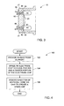
- FIG. 4 is a process flow diagram of another approach of producing the electrode support 10.
- process 100 begins at 102, where the electrode support 10 is provided.
- Process 100 may then proceed to 104, where the electrode chip 26 is brazed to both the side portion 22 and the center portion 20 of the electrode support 10.
- Process 100 may then proceed to 106, where a material removal process such as, for example, machining is used to remove a section of the electrode chip 26 and thereby create the spark gap 50 as shown in FIG. 4 .
- a material removal process such as, for example, machining is used to remove a section of the electrode chip 26 and thereby create the spark gap 50 as shown in FIG. 4 .
- brazing may be used to join the electrode chip 26 to the electrode support 10. Brazing may reduce or substantially eliminate some of issues that are created with welding. For example, a brazed configuration between the electrode chip 26 and the electrode support 10 does not consume a portion of the relatively costly electrode material, unlike a weld joint. Moreover, the electrode support 10 and the electrode chip 26 are both constructed from materials having substantially the same coefficient of thermal expansion. The substantially similar coefficients of thermal expansion between the electrode support 10 and the electrode chip 26 facilitate brazing of the electrode support 10 and the electrode chip 26.
Landscapes
- Engineering & Computer Science (AREA)
- Manufacturing & Machinery (AREA)
- Spark Plugs (AREA)
Abstract
Description
- The subject matter disclosed herein relates to a method of producing an electrode support for a spark plug, and more specifically to a method of producing an electrode for a spark plug using brazing.
- Spark plugs include an electrode chip located at an end of a center electrode. A separate chip is also located on an end of a side or ground electrode. An air or spark gap is located between the chip positioned on the center electrode and the chip positioned on the ground electrode. In one approach, the spark plug is manufactured by welding a single chip to both the center electrode and the ground electrode. Then, the chip is then machined to create the spark gap between the center electrode and the ground electrode. The chip is generally constructed from a precious or noble metal such as, for example, a platinum based alloy. Noble and precious metals usually have a relatively high cost.
- Several drawbacks in the current manufacturing approach generally exist. For example, welding may result in cracks in a weld joint, due to a mismatch in the coefficient of thermal expansion between the different materials that the chip and the center and ground electrodes are constructed from. Also, welding consumes a portion of the relatively costly material the chip is constructed from.
- According to one aspect of the invention, a method of producing an electrode support for a spark plug is provided. The method includes providing the electrode support. The method includes brazing a chip to the electrode support.
- According to another aspect of the invention, a spark plug is provided having an electrode support, a side chip, and a center chip. The electrode support includes a center portion and a side portion. The side chip is brazed to both the center portion of the electrode support. The center chip is brazed to the center portion of the electrode support.
- These and other advantages and features will become more apparent from the following description taken in conjunction with the drawings.
- The subject matter, which is regarded as the invention, is particularly pointed out and distinctly claimed in the claims at the conclusion of the specification. The foregoing and other features, and advantages of the invention are apparent from the following detailed description taken in conjunction with the accompanying drawings in which:
-
FIG. 1 is a top view of an electrode support for a spark plug; -
FIG. 2 is a cross-sectioned view of the electrode support shown inFIG. 1 ; -
FIG. 3 is an illustration of the electrode support with a spark gap; and -
FIG. 4 is a process flow diagram of one approach to produce the electrode support shown inFIG. 4 . - The detailed description explains embodiments of the invention, together with advantages and features, by way of example with reference to the drawings.
-
FIG. 1 is an illustration of anexample electrode support 10 for a spark plug (not shown). In one example embodiment, theelectrode support 10 may be used in a spark plug of an industrial engine. Theelectrode support 10 includes acenter portion 20 and a plurality of ground orside portions 22. Theelectrode support 10 also includes a plurality ofelectrode chips 26 attached to theelectrode support 10. Specifically, in the embodiment as shown inFIG. 1 , theelectrode support 10 is part of a multi-electrode spark plug. In the embodiment as shown, theelectrode support 10 includes fourelectrode chips 26 that are each spaced generally equidistant from one another, however, it is to be understood that any number ofside portions 22 may be used as well. - The
electrode chip 26 is constructed from an electrode material. A portion of the electrode material is eventually removed by a material removal process such as, for example, machining, to create a spark gap 50 (shown inFIG. 3 ). The electrode material may be, for example, a noble metal. In one embodiment, the electrode material is a precious metal such as, for example, platinum or silver. -
FIG. 2 is a cross-sectioned view of theelectrode support 10 shown inFIG. 1 taken along section C-C. Referring now to bothFIGS. 1-2 , each of theelectrode chips 26 are attached to anend portion 40 of thecenter portion 20. Each of theelectrode chips 26 are also attached to anend portion 42 of a corresponding one of theside portions 22 of theelectrode support 10. Specifically, asurface 43 of each of theelectrode chips 26 are attached to anouter surface 44 of thecenter portion 20. Asurface 45 of each of theelectrode chips 26 are attached to anouter surface 46 of thecorresponding side portion 22. Theouter surface 46 of theside portion 22 is oriented to generally oppose theouter surface 44 of thecenter portion 20. - The
electrode chip 26 is attached to either theouter surface 44 of thecenter portion 20 or theouter surface 46 of thecorresponding side portion 22 by a brazing process. Brazing theelectrode chip 26 to the electrode support involves employing a filler material to join the electrode material to theelectrode support 10. Brazing may improve contact and subsequent heat transfer between theelectrode chip 26 and theelectrode support 10 when compared to some other types of joining processes such as, for example, welding. Brazing also reduces stress between theelectrode ship 26 and the electrode support 10 by substantially reducing or eliminating the built-in stress risers that are generally associated with other types of joining approaches. Moreover, because a filler material is used, the brazed configuration between theelectrode chip 26 and theelectrode support 10 does not consume a portion of the relatively costly electrode material, unlike a weld joint. - The
electrode support 10 may be constructed from a metal material that has a relatively low coefficient of thermal expansion such as, for example, nickel iron alloys. For example, in one embodiment, theelectrode support 10 includes a coefficient of thermal expansion that ranges from between about 4 x 10⁻⁶ K-1 to about 12 x 10-6 K-1. In one example embodiment, theelectrode support 10 may be constructed an iron-nickel-cobalt alloy conforming to ASTM F-15 or UNS N14052. Specifically, the electrode support 10 and theelectrode chip 26 may both be constructed from materials having substantially the same coefficient of thermal expansion. For example, in one embodiment, theelectrode chip 26 may be constructed from a noble metal having a coefficient of thermal expansion that ranges from between about 5 x 10⁻⁶ K-1 to about 10 x 10-6 K-1. The compatible coefficients of thermal expansion results in a reduced amount of stress on the braze joint (not shown) when theelectrode chip 26 and theelectrode support 10 are brazed together compared to other joining approaches such as welding. -
FIG. 3 is an illustration of theelectrode support 10 with thespark gap 50. Specifically, thespark gap 50 is located between aside electrode chip 80 that is brazed to theside portion 22 and acenter electrode chip 82 that is brazed to thecenter portion 20. Thespark gap 50 includes a distance D measured from asurface 84 of theside electrode chip 80 and asurface 86 of thecenter electrode chip 82. Thesurface 84 of theside electrode chip 80 generally opposes thesurface 86 of thecenter electrode chip 86. Thespark gap 50 represents a portion of the electrode material S (shown in phantom line inFIG. 2 ) that has been removed. Thespark gap 50 may be created by a material removal process such as, for example, machining. -
FIG. 4 is a process flow diagram of another approach of producing theelectrode support 10. Referring now toFIGS. 1-4 ,process 100 begins at 102, where theelectrode support 10 is provided.Process 100 may then proceed to 104, where theelectrode chip 26 is brazed to both theside portion 22 and thecenter portion 20 of theelectrode support 10.Process 100 may then proceed to 106, where a material removal process such as, for example, machining is used to remove a section of theelectrode chip 26 and thereby create thespark gap 50 as shown inFIG. 4 . - Referring generally to
FIGS. 1-4 , brazing may be used to join theelectrode chip 26 to theelectrode support 10. Brazing may reduce or substantially eliminate some of issues that are created with welding. For example, a brazed configuration between theelectrode chip 26 and theelectrode support 10 does not consume a portion of the relatively costly electrode material, unlike a weld joint. Moreover, theelectrode support 10 and theelectrode chip 26 are both constructed from materials having substantially the same coefficient of thermal expansion. The substantially similar coefficients of thermal expansion between theelectrode support 10 and theelectrode chip 26 facilitate brazing of theelectrode support 10 and theelectrode chip 26. - While the invention has been described in detail in connection with only a limited number of embodiments, it should be readily understood that the invention is not limited to such disclosed embodiments. Rather, the invention can be modified to incorporate any number of variations, alterations, substitutions or equivalent arrangements not heretofore described, but which are commensurate with the spirit and scope of the invention. Additionally, while various embodiments of the invention have been described, it is to be understood that aspects of the invention may include only some of the described embodiments. Accordingly, the invention is not to be seen as limited by the foregoing description, but is only limited by the scope of the appended claims.
Claims (15)
- A method of producing an electrode support for a spark plug, comprising:providing (102) the electrode support; andbrazing (104) a chip to the electrode support.
- The method as recited in claim 1, comprising brazing (104) a portion of an outer surface of the chip to a center portion of the electrode support, and another portion of the outer surface of the chip to a side portion of the electrode support.
- The method as recited in claim 2, comprising brazing (104) the chip to both the center portion and the side portion of the electrode support.
- The method as recited in claim 1, 2 or 3 comprising substantially removing (106) a section of an electrode material from the chip to create a spark gap.
- The method as recited in claim 4, comprising substantially removing (106) the section from the chip by machining.
- The method as recited in any preceding claim, comprising constructing the electrode support from a metal based material that has a coefficient of thermal expansion that ranges from between about 4 x 10⁻⁶ K-1 to about 12 x 10-6 K-1.
- The method as recited in any preceding claim, wherein a support coefficient of thermal expansion of the electrode support is substantially the same as an electrode coefficient of thermal expansion of an electrode material of the chip.
- The method as recited in any preceding claim, wherein the chip is constructed at least in part from one of a noble metal and a precious metal.
- The method as recited in any preceding claim, wherein the electrode support is constructed from an iron-nickel-cobalt alloy conforming to ASTM F-15.
- A method as recited in any preceding claim, comprising:providing (102) an electrode support, the electrode support having a center portion and a side portion;brazing (104) the chip to both the center portion and the side portion of the electrode support; andremoving (1060 a section of an electrode material from the chip to create a spark gap.
- A spark plug, comprising:an electrode support (10) having a center portion (20) mand a side portion (22);a side chip (80) brazed to both the center portion (20) of the electrode support; anda center chip (82) brazed to the center portion (20) of the electrode support.
- The spark plug as recited in claim 11, wherein the electrode support (10) is constructed from a metal based material that has a coefficient of thermal expansion that ranges from between about 4 x 10⁻⁶ K-1 to about 12 x 10-6 K-1.
- The spark plug as recited in claim 11 or claim 12, wherein a support coefficient of thermal expansion of the electrode support is substantially the same as an electrode coefficient of thermal expansion of an electrode material of the side chip and the center chip.
- The spark plug as recited in claim 11, 12 or 13 wherein the side chip (80) and the center chip (82) are constructed at least in part from one of a noble metal and a precious metal.
- The method as recited in claim 11, 12, 13 or 14, wherein the electrode support (10) is constructed from an iron-nickel-cobalt alloy conforming to ASTM F-15.
Applications Claiming Priority (1)
| Application Number | Priority Date | Filing Date | Title |
|---|---|---|---|
| US13/357,314 US8912713B2 (en) | 2012-01-24 | 2012-01-24 | Method of producing an electrode support using brazing |
Publications (3)
| Publication Number | Publication Date |
|---|---|
| EP2621038A2 true EP2621038A2 (en) | 2013-07-31 |
| EP2621038A3 EP2621038A3 (en) | 2015-04-08 |
| EP2621038B1 EP2621038B1 (en) | 2020-03-18 |
Family
ID=47598727
Family Applications (1)
| Application Number | Title | Priority Date | Filing Date |
|---|---|---|---|
| EP13152345.8A Active EP2621038B1 (en) | 2012-01-24 | 2013-01-23 | Method of producing an electrode support using brazing |
Country Status (2)
| Country | Link |
|---|---|
| US (1) | US8912713B2 (en) |
| EP (1) | EP2621038B1 (en) |
Cited By (2)
| Publication number | Priority date | Publication date | Assignee | Title |
|---|---|---|---|---|
| WO2020025184A1 (en) * | 2018-08-02 | 2020-02-06 | Robert Bosch Gmbh | Method for manufacturing a spark plug electrode assembly and spark plug, spark plug electrode assembly, and spark plug |
| WO2023030766A1 (en) * | 2021-09-06 | 2023-03-09 | Robert Bosch Gmbh | Method for producing a spark plug, and spark plug |
Families Citing this family (4)
| Publication number | Priority date | Publication date | Assignee | Title |
|---|---|---|---|---|
| US10215412B2 (en) | 2012-11-02 | 2019-02-26 | General Electric Company | System and method for load control with diffusion combustion in a stoichiometric exhaust gas recirculation gas turbine system |
| US9431797B2 (en) | 2014-10-08 | 2016-08-30 | General Electric Company | Spark plug electrode gap setting tool |
| DE102015118935B4 (en) * | 2015-07-23 | 2017-04-20 | Federal-Mogul Ignition Gmbh | Method for producing a spark plug |
| CN114342196B (en) | 2019-09-06 | 2022-09-27 | 联邦-富豪燃气有限责任公司 | Electrode material for spark plug |
Family Cites Families (11)
| Publication number | Priority date | Publication date | Assignee | Title |
|---|---|---|---|---|
| US3586903A (en) | 1968-05-13 | 1971-06-22 | Globe Union Inc | Spark gap devices |
| JPH07109783B2 (en) | 1989-05-29 | 1995-11-22 | 日本特殊陶業株式会社 | Spark plug for internal combustion engine |
| JPH0461779A (en) * | 1990-06-27 | 1992-02-27 | Ngk Spark Plug Co Ltd | Spark plug with bevel-shaped outside electrode |
| GB2276207B (en) * | 1993-03-18 | 1996-09-04 | Nippon Denso Co | A spark plug and a method of producing the same |
| CA2127424C (en) | 1993-08-25 | 2006-01-24 | John Sungheup Yang | Cash box with bill weights |
| JP3676610B2 (en) | 1999-03-16 | 2005-07-27 | 炳霖 ▲楊▼ | Chipless surge absorber for converting and absorbing surge energy by dielectric breakdown of air chamber and method for manufacturing the same |
| JP4306115B2 (en) | 2000-11-06 | 2009-07-29 | 株式会社デンソー | Manufacturing method of spark plug |
| JP2003142226A (en) * | 2001-10-31 | 2003-05-16 | Ngk Spark Plug Co Ltd | Spark plug |
| EP1841028B1 (en) * | 2006-03-29 | 2013-11-20 | NGK Spark Plug Co., Ltd. | Spark plug for internal combustion engine |
| JP5525454B2 (en) * | 2008-01-28 | 2014-06-18 | フラム・グループ・アイピー・エルエルシー | High position thread ground shield |
| US8485857B1 (en) * | 2012-01-24 | 2013-07-16 | General Electric Company | Method of producing a spark gap for an electrode support using sacrificial material |
-
2012
- 2012-01-24 US US13/357,314 patent/US8912713B2/en active Active
-
2013
- 2013-01-23 EP EP13152345.8A patent/EP2621038B1/en active Active
Non-Patent Citations (1)
| Title |
|---|
| None |
Cited By (8)
| Publication number | Priority date | Publication date | Assignee | Title |
|---|---|---|---|---|
| WO2020025184A1 (en) * | 2018-08-02 | 2020-02-06 | Robert Bosch Gmbh | Method for manufacturing a spark plug electrode assembly and spark plug, spark plug electrode assembly, and spark plug |
| CN112470353A (en) * | 2018-08-02 | 2021-03-09 | 罗伯特·博世有限公司 | Method for producing a spark plug electrode arrangement and a spark plug, spark plug electrode arrangement and spark plug |
| JP2021531626A (en) * | 2018-08-02 | 2021-11-18 | ロベルト・ボッシュ・ゲゼルシャフト・ミト・ベシュレンクテル・ハフツングRobert Bosch Gmbh | Spark plug electrode structure and method of manufacturing spark plug, spark plug electrode structure, and spark plug |
| US11437788B2 (en) | 2018-08-02 | 2022-09-06 | Robert Bosch Gmbh | Method for manufacturing a spark plug electrode system and a spark plug, spark plug electrode system, and spark plug |
| CN112470353B (en) * | 2018-08-02 | 2022-11-15 | 罗伯特·博世有限公司 | Method for producing a spark plug electrode arrangement and a spark plug, spark plug electrode arrangement and spark plug |
| JP7377851B2 (en) | 2018-08-02 | 2023-11-10 | ロベルト・ボッシュ・ゲゼルシャフト・ミト・ベシュレンクテル・ハフツング | Spark plug electrode structure and method of manufacturing spark plugs |
| WO2023030766A1 (en) * | 2021-09-06 | 2023-03-09 | Robert Bosch Gmbh | Method for producing a spark plug, and spark plug |
| US12272930B2 (en) | 2021-09-06 | 2025-04-08 | Robert Bosch Gmbh | Method for producing a spark plug, and spark plug |
Also Published As
| Publication number | Publication date |
|---|---|
| US20130187530A1 (en) | 2013-07-25 |
| EP2621038A3 (en) | 2015-04-08 |
| US8912713B2 (en) | 2014-12-16 |
| EP2621038B1 (en) | 2020-03-18 |
Similar Documents
| Publication | Publication Date | Title |
|---|---|---|
| EP2621038A2 (en) | Method of producing an electrode support using brazing | |
| US20070290593A1 (en) | Spark Plug With Fine Wire Ground Electrode | |
| JP5048063B2 (en) | Spark plug for internal combustion engine | |
| JP5905056B2 (en) | Spark plug and method of manufacturing spark plug | |
| KR20110126654A (en) | Spark plug and manufacturing method thereof | |
| EP1929598B1 (en) | Spark plug with welded sleeve on electrode | |
| EP2621037A2 (en) | Method of producing a spark gap for an electrode support using sacrificial material | |
| CN102859815A (en) | Spark plug for internal combustion engine and method of manufacturing spark plug | |
| JP6320354B2 (en) | Spark plug and manufacturing method thereof | |
| JP5535799B2 (en) | Repair method of metal parts and repaired metal parts | |
| JP5847259B2 (en) | Spark plug | |
| JP4696981B2 (en) | Spark plug for internal combustion engine | |
| EP3542941B1 (en) | Fixtures for additively manufactured workpieces | |
| JP5144818B2 (en) | Spark plug | |
| JP4885837B2 (en) | Manufacturing method of spark plug | |
| JP6270802B2 (en) | Spark plug | |
| JP5995912B2 (en) | Spark plug and method of manufacturing spark plug | |
| CN103216335B (en) | Process of fabricating a fuel nozzel assembly | |
| WO2017037969A1 (en) | Spark plug | |
| CN105247747A (en) | Method for manufacturing spark plug for internal combustion engine | |
| JP5331179B2 (en) | Manufacturing method of spark plug | |
| CN105229878B (en) | Spark plug | |
| JP6152140B2 (en) | Nozzle and nozzle manufacturing method | |
| JP4764212B2 (en) | Spark plug for internal combustion engine | |
| EP1995546A1 (en) | Method of producing a radiator, and radiator produced by such a method |
Legal Events
| Date | Code | Title | Description |
|---|---|---|---|
| PUAI | Public reference made under article 153(3) epc to a published international application that has entered the european phase |
Free format text: ORIGINAL CODE: 0009012 |
|
| AK | Designated contracting states |
Kind code of ref document: A2 Designated state(s): AL AT BE BG CH CY CZ DE DK EE ES FI FR GB GR HR HU IE IS IT LI LT LU LV MC MK MT NL NO PL PT RO RS SE SI SK SM TR |
|
| AX | Request for extension of the european patent |
Extension state: BA ME |
|
| PUAL | Search report despatched |
Free format text: ORIGINAL CODE: 0009013 |
|
| AK | Designated contracting states |
Kind code of ref document: A3 Designated state(s): AL AT BE BG CH CY CZ DE DK EE ES FI FR GB GR HR HU IE IS IT LI LT LU LV MC MK MT NL NO PL PT RO RS SE SI SK SM TR |
|
| AX | Request for extension of the european patent |
Extension state: BA ME |
|
| RIC1 | Information provided on ipc code assigned before grant |
Ipc: H01T 13/46 20060101ALI20150227BHEP Ipc: H01T 21/06 20060101AFI20150227BHEP Ipc: H01T 13/20 20060101ALI20150227BHEP |
|
| 17P | Request for examination filed |
Effective date: 20151008 |
|
| RBV | Designated contracting states (corrected) |
Designated state(s): AL AT BE BG CH CY CZ DE DK EE ES FI FR GB GR HR HU IE IS IT LI LT LU LV MC MK MT NL NO PL PT RO RS SE SI SK SM TR |
|
| RAP1 | Party data changed (applicant data changed or rights of an application transferred) |
Owner name: AI ALPINE US BIDCO INC. |
|
| GRAP | Despatch of communication of intention to grant a patent |
Free format text: ORIGINAL CODE: EPIDOSNIGR1 |
|
| STAA | Information on the status of an ep patent application or granted ep patent |
Free format text: STATUS: GRANT OF PATENT IS INTENDED |
|
| INTG | Intention to grant announced |
Effective date: 20191023 |
|
| GRAS | Grant fee paid |
Free format text: ORIGINAL CODE: EPIDOSNIGR3 |
|
| GRAA | (expected) grant |
Free format text: ORIGINAL CODE: 0009210 |
|
| STAA | Information on the status of an ep patent application or granted ep patent |
Free format text: STATUS: THE PATENT HAS BEEN GRANTED |
|
| AK | Designated contracting states |
Kind code of ref document: B1 Designated state(s): AL AT BE BG CH CY CZ DE DK EE ES FI FR GB GR HR HU IE IS IT LI LT LU LV MC MK MT NL NO PL PT RO RS SE SI SK SM TR |
|
| REG | Reference to a national code |
Ref country code: GB Ref legal event code: FG4D |
|
| REG | Reference to a national code |
Ref country code: DE Ref legal event code: R096 Ref document number: 602013066873 Country of ref document: DE |
|
| REG | Reference to a national code |
Ref country code: AT Ref legal event code: REF Ref document number: 1247034 Country of ref document: AT Kind code of ref document: T Effective date: 20200415 Ref country code: IE Ref legal event code: FG4D |
|
| PG25 | Lapsed in a contracting state [announced via postgrant information from national office to epo] |
Ref country code: NO Free format text: LAPSE BECAUSE OF FAILURE TO SUBMIT A TRANSLATION OF THE DESCRIPTION OR TO PAY THE FEE WITHIN THE PRESCRIBED TIME-LIMIT Effective date: 20200618 Ref country code: RS Free format text: LAPSE BECAUSE OF FAILURE TO SUBMIT A TRANSLATION OF THE DESCRIPTION OR TO PAY THE FEE WITHIN THE PRESCRIBED TIME-LIMIT Effective date: 20200318 Ref country code: FI Free format text: LAPSE BECAUSE OF FAILURE TO SUBMIT A TRANSLATION OF THE DESCRIPTION OR TO PAY THE FEE WITHIN THE PRESCRIBED TIME-LIMIT Effective date: 20200318 |
|
| REG | Reference to a national code |
Ref country code: NL Ref legal event code: MP Effective date: 20200318 |
|
| PG25 | Lapsed in a contracting state [announced via postgrant information from national office to epo] |
Ref country code: GR Free format text: LAPSE BECAUSE OF FAILURE TO SUBMIT A TRANSLATION OF THE DESCRIPTION OR TO PAY THE FEE WITHIN THE PRESCRIBED TIME-LIMIT Effective date: 20200619 Ref country code: SE Free format text: LAPSE BECAUSE OF FAILURE TO SUBMIT A TRANSLATION OF THE DESCRIPTION OR TO PAY THE FEE WITHIN THE PRESCRIBED TIME-LIMIT Effective date: 20200318 Ref country code: LV Free format text: LAPSE BECAUSE OF FAILURE TO SUBMIT A TRANSLATION OF THE DESCRIPTION OR TO PAY THE FEE WITHIN THE PRESCRIBED TIME-LIMIT Effective date: 20200318 Ref country code: HR Free format text: LAPSE BECAUSE OF FAILURE TO SUBMIT A TRANSLATION OF THE DESCRIPTION OR TO PAY THE FEE WITHIN THE PRESCRIBED TIME-LIMIT Effective date: 20200318 Ref country code: BG Free format text: LAPSE BECAUSE OF FAILURE TO SUBMIT A TRANSLATION OF THE DESCRIPTION OR TO PAY THE FEE WITHIN THE PRESCRIBED TIME-LIMIT Effective date: 20200618 |
|
| REG | Reference to a national code |
Ref country code: LT Ref legal event code: MG4D |
|
| PG25 | Lapsed in a contracting state [announced via postgrant information from national office to epo] |
Ref country code: NL Free format text: LAPSE BECAUSE OF FAILURE TO SUBMIT A TRANSLATION OF THE DESCRIPTION OR TO PAY THE FEE WITHIN THE PRESCRIBED TIME-LIMIT Effective date: 20200318 |
|
| PG25 | Lapsed in a contracting state [announced via postgrant information from national office to epo] |
Ref country code: EE Free format text: LAPSE BECAUSE OF FAILURE TO SUBMIT A TRANSLATION OF THE DESCRIPTION OR TO PAY THE FEE WITHIN THE PRESCRIBED TIME-LIMIT Effective date: 20200318 Ref country code: SM Free format text: LAPSE BECAUSE OF FAILURE TO SUBMIT A TRANSLATION OF THE DESCRIPTION OR TO PAY THE FEE WITHIN THE PRESCRIBED TIME-LIMIT Effective date: 20200318 Ref country code: CZ Free format text: LAPSE BECAUSE OF FAILURE TO SUBMIT A TRANSLATION OF THE DESCRIPTION OR TO PAY THE FEE WITHIN THE PRESCRIBED TIME-LIMIT Effective date: 20200318 Ref country code: RO Free format text: LAPSE BECAUSE OF FAILURE TO SUBMIT A TRANSLATION OF THE DESCRIPTION OR TO PAY THE FEE WITHIN THE PRESCRIBED TIME-LIMIT Effective date: 20200318 Ref country code: IS Free format text: LAPSE BECAUSE OF FAILURE TO SUBMIT A TRANSLATION OF THE DESCRIPTION OR TO PAY THE FEE WITHIN THE PRESCRIBED TIME-LIMIT Effective date: 20200718 Ref country code: SK Free format text: LAPSE BECAUSE OF FAILURE TO SUBMIT A TRANSLATION OF THE DESCRIPTION OR TO PAY THE FEE WITHIN THE PRESCRIBED TIME-LIMIT Effective date: 20200318 Ref country code: LT Free format text: LAPSE BECAUSE OF FAILURE TO SUBMIT A TRANSLATION OF THE DESCRIPTION OR TO PAY THE FEE WITHIN THE PRESCRIBED TIME-LIMIT Effective date: 20200318 Ref country code: PT Free format text: LAPSE BECAUSE OF FAILURE TO SUBMIT A TRANSLATION OF THE DESCRIPTION OR TO PAY THE FEE WITHIN THE PRESCRIBED TIME-LIMIT Effective date: 20200812 |
|
| REG | Reference to a national code |
Ref country code: DE Ref legal event code: R097 Ref document number: 602013066873 Country of ref document: DE |
|
| PLBE | No opposition filed within time limit |
Free format text: ORIGINAL CODE: 0009261 |
|
| STAA | Information on the status of an ep patent application or granted ep patent |
Free format text: STATUS: NO OPPOSITION FILED WITHIN TIME LIMIT |
|
| PG25 | Lapsed in a contracting state [announced via postgrant information from national office to epo] |
Ref country code: ES Free format text: LAPSE BECAUSE OF FAILURE TO SUBMIT A TRANSLATION OF THE DESCRIPTION OR TO PAY THE FEE WITHIN THE PRESCRIBED TIME-LIMIT Effective date: 20200318 Ref country code: DK Free format text: LAPSE BECAUSE OF FAILURE TO SUBMIT A TRANSLATION OF THE DESCRIPTION OR TO PAY THE FEE WITHIN THE PRESCRIBED TIME-LIMIT Effective date: 20200318 Ref country code: IT Free format text: LAPSE BECAUSE OF FAILURE TO SUBMIT A TRANSLATION OF THE DESCRIPTION OR TO PAY THE FEE WITHIN THE PRESCRIBED TIME-LIMIT Effective date: 20200318 |
|
| 26N | No opposition filed |
Effective date: 20201221 |
|
| PG25 | Lapsed in a contracting state [announced via postgrant information from national office to epo] |
Ref country code: PL Free format text: LAPSE BECAUSE OF FAILURE TO SUBMIT A TRANSLATION OF THE DESCRIPTION OR TO PAY THE FEE WITHIN THE PRESCRIBED TIME-LIMIT Effective date: 20200318 |
|
| PG25 | Lapsed in a contracting state [announced via postgrant information from national office to epo] |
Ref country code: SI Free format text: LAPSE BECAUSE OF FAILURE TO SUBMIT A TRANSLATION OF THE DESCRIPTION OR TO PAY THE FEE WITHIN THE PRESCRIBED TIME-LIMIT Effective date: 20200318 |
|
| PG25 | Lapsed in a contracting state [announced via postgrant information from national office to epo] |
Ref country code: MC Free format text: LAPSE BECAUSE OF FAILURE TO SUBMIT A TRANSLATION OF THE DESCRIPTION OR TO PAY THE FEE WITHIN THE PRESCRIBED TIME-LIMIT Effective date: 20200318 |
|
| REG | Reference to a national code |
Ref country code: CH Ref legal event code: PL |
|
| GBPC | Gb: european patent ceased through non-payment of renewal fee |
Effective date: 20210123 |
|
| PG25 | Lapsed in a contracting state [announced via postgrant information from national office to epo] |
Ref country code: LU Free format text: LAPSE BECAUSE OF NON-PAYMENT OF DUE FEES Effective date: 20210123 |
|
| REG | Reference to a national code |
Ref country code: BE Ref legal event code: MM Effective date: 20210131 |
|
| PG25 | Lapsed in a contracting state [announced via postgrant information from national office to epo] |
Ref country code: FR Free format text: LAPSE BECAUSE OF NON-PAYMENT OF DUE FEES Effective date: 20210131 |
|
| PG25 | Lapsed in a contracting state [announced via postgrant information from national office to epo] |
Ref country code: LI Free format text: LAPSE BECAUSE OF NON-PAYMENT OF DUE FEES Effective date: 20210131 Ref country code: GB Free format text: LAPSE BECAUSE OF NON-PAYMENT OF DUE FEES Effective date: 20210123 Ref country code: CH Free format text: LAPSE BECAUSE OF NON-PAYMENT OF DUE FEES Effective date: 20210131 |
|
| PG25 | Lapsed in a contracting state [announced via postgrant information from national office to epo] |
Ref country code: IE Free format text: LAPSE BECAUSE OF NON-PAYMENT OF DUE FEES Effective date: 20210123 |
|
| PG25 | Lapsed in a contracting state [announced via postgrant information from national office to epo] |
Ref country code: BE Free format text: LAPSE BECAUSE OF NON-PAYMENT OF DUE FEES Effective date: 20210131 |
|
| PG25 | Lapsed in a contracting state [announced via postgrant information from national office to epo] |
Ref country code: HU Free format text: LAPSE BECAUSE OF FAILURE TO SUBMIT A TRANSLATION OF THE DESCRIPTION OR TO PAY THE FEE WITHIN THE PRESCRIBED TIME-LIMIT; INVALID AB INITIO Effective date: 20130123 |
|
| PG25 | Lapsed in a contracting state [announced via postgrant information from national office to epo] |
Ref country code: CY Free format text: LAPSE BECAUSE OF FAILURE TO SUBMIT A TRANSLATION OF THE DESCRIPTION OR TO PAY THE FEE WITHIN THE PRESCRIBED TIME-LIMIT Effective date: 20200318 |
|
| P01 | Opt-out of the competence of the unified patent court (upc) registered |
Effective date: 20230602 |
|
| PG25 | Lapsed in a contracting state [announced via postgrant information from national office to epo] |
Ref country code: MK Free format text: LAPSE BECAUSE OF FAILURE TO SUBMIT A TRANSLATION OF THE DESCRIPTION OR TO PAY THE FEE WITHIN THE PRESCRIBED TIME-LIMIT Effective date: 20200318 |
|
| PG25 | Lapsed in a contracting state [announced via postgrant information from national office to epo] |
Ref country code: TR Free format text: LAPSE BECAUSE OF FAILURE TO SUBMIT A TRANSLATION OF THE DESCRIPTION OR TO PAY THE FEE WITHIN THE PRESCRIBED TIME-LIMIT Effective date: 20200318 |
|
| PG25 | Lapsed in a contracting state [announced via postgrant information from national office to epo] |
Ref country code: MT Free format text: LAPSE BECAUSE OF FAILURE TO SUBMIT A TRANSLATION OF THE DESCRIPTION OR TO PAY THE FEE WITHIN THE PRESCRIBED TIME-LIMIT Effective date: 20200318 |
|
| PGFP | Annual fee paid to national office [announced via postgrant information from national office to epo] |
Ref country code: AT Payment date: 20241220 Year of fee payment: 13 |
|
| REG | Reference to a national code |
Ref country code: AT Ref legal event code: UEP Ref document number: 1247034 Country of ref document: AT Kind code of ref document: T Effective date: 20200318 |
|
| PGFP | Annual fee paid to national office [announced via postgrant information from national office to epo] |
Ref country code: DE Payment date: 20251217 Year of fee payment: 14 |