EP2620736A2 - Heat exchanger and air-conditioning apparatus having the same - Google Patents
Heat exchanger and air-conditioning apparatus having the same Download PDFInfo
- Publication number
- EP2620736A2 EP2620736A2 EP12182717.4A EP12182717A EP2620736A2 EP 2620736 A2 EP2620736 A2 EP 2620736A2 EP 12182717 A EP12182717 A EP 12182717A EP 2620736 A2 EP2620736 A2 EP 2620736A2
- Authority
- EP
- European Patent Office
- Prior art keywords
- pipe
- aluminum
- pipes
- heat exchanger
- unit
- Prior art date
- Legal status (The legal status is an assumption and is not a legal conclusion. Google has not performed a legal analysis and makes no representation as to the accuracy of the status listed.)
- Granted
Links
- 238000004378 air conditioning Methods 0.000 title claims description 18
- 229910052782 aluminium Inorganic materials 0.000 claims abstract description 122
- XAGFODPZIPBFFR-UHFFFAOYSA-N aluminium Chemical compound [Al] XAGFODPZIPBFFR-UHFFFAOYSA-N 0.000 claims abstract description 119
- 239000003507 refrigerant Substances 0.000 claims abstract description 65
- 238000005260 corrosion Methods 0.000 claims abstract description 53
- RYGMFSIKBFXOCR-UHFFFAOYSA-N Copper Chemical compound [Cu] RYGMFSIKBFXOCR-UHFFFAOYSA-N 0.000 claims abstract description 49
- 229910052802 copper Inorganic materials 0.000 claims abstract description 49
- 239000010949 copper Substances 0.000 claims abstract description 49
- 229910000838 Al alloy Inorganic materials 0.000 claims abstract description 48
- 239000007788 liquid Substances 0.000 claims abstract description 46
- 239000011810 insulating material Substances 0.000 claims abstract description 20
- 229910000881 Cu alloy Inorganic materials 0.000 claims abstract description 14
- 230000007797 corrosion Effects 0.000 abstract description 46
- XLYOFNOQVPJJNP-UHFFFAOYSA-N water Substances O XLYOFNOQVPJJNP-UHFFFAOYSA-N 0.000 abstract description 22
- JPVYNHNXODAKFH-UHFFFAOYSA-N Cu2+ Chemical compound [Cu+2] JPVYNHNXODAKFH-UHFFFAOYSA-N 0.000 abstract description 12
- 229910001431 copper ion Inorganic materials 0.000 abstract description 9
- 238000009792 diffusion process Methods 0.000 abstract description 4
- 230000001143 conditioned effect Effects 0.000 description 8
- 238000005057 refrigeration Methods 0.000 description 8
- 229910001369 Brass Inorganic materials 0.000 description 7
- 239000010951 brass Substances 0.000 description 7
- 238000009833 condensation Methods 0.000 description 5
- 230000005494 condensation Effects 0.000 description 5
- 238000001816 cooling Methods 0.000 description 4
- 229910052751 metal Inorganic materials 0.000 description 4
- 239000002184 metal Substances 0.000 description 4
- HCHKCACWOHOZIP-UHFFFAOYSA-N Zinc Chemical compound [Zn] HCHKCACWOHOZIP-UHFFFAOYSA-N 0.000 description 3
- -1 aluminum ions Chemical class 0.000 description 3
- 238000005219 brazing Methods 0.000 description 3
- 238000007791 dehumidification Methods 0.000 description 3
- 239000006023 eutectic alloy Substances 0.000 description 3
- 230000005496 eutectics Effects 0.000 description 3
- 239000000463 material Substances 0.000 description 3
- 150000002739 metals Chemical class 0.000 description 3
- 239000011701 zinc Substances 0.000 description 3
- 229910052725 zinc Inorganic materials 0.000 description 3
- 238000000576 coating method Methods 0.000 description 2
- 239000011162 core material Substances 0.000 description 2
- 238000005336 cracking Methods 0.000 description 2
- 238000010586 diagram Methods 0.000 description 2
- 238000005516 engineering process Methods 0.000 description 2
- 230000005484 gravity Effects 0.000 description 2
- 238000010438 heat treatment Methods 0.000 description 2
- 238000009434 installation Methods 0.000 description 2
- 239000007769 metal material Substances 0.000 description 2
- PWHULOQIROXLJO-UHFFFAOYSA-N Manganese Chemical compound [Mn] PWHULOQIROXLJO-UHFFFAOYSA-N 0.000 description 1
- 108010001267 Protein Subunits Proteins 0.000 description 1
- 230000015572 biosynthetic process Effects 0.000 description 1
- 230000003247 decreasing effect Effects 0.000 description 1
- 239000000428 dust Substances 0.000 description 1
- 230000000694 effects Effects 0.000 description 1
- 229910052748 manganese Inorganic materials 0.000 description 1
- 239000011572 manganese Substances 0.000 description 1
- 230000002265 prevention Effects 0.000 description 1
- 238000011144 upstream manufacturing Methods 0.000 description 1
Images


Classifications
-
- F—MECHANICAL ENGINEERING; LIGHTING; HEATING; WEAPONS; BLASTING
- F24—HEATING; RANGES; VENTILATING
- F24F—AIR-CONDITIONING; AIR-HUMIDIFICATION; VENTILATION; USE OF AIR CURRENTS FOR SCREENING
- F24F1/00—Room units for air-conditioning, e.g. separate or self-contained units or units receiving primary air from a central station
- F24F1/0007—Indoor units, e.g. fan coil units
- F24F1/0071—Indoor units, e.g. fan coil units with means for purifying supplied air
-
- F—MECHANICAL ENGINEERING; LIGHTING; HEATING; WEAPONS; BLASTING
- F28—HEAT EXCHANGE IN GENERAL
- F28F—DETAILS OF HEAT-EXCHANGE AND HEAT-TRANSFER APPARATUS, OF GENERAL APPLICATION
- F28F21/00—Constructions of heat-exchange apparatus characterised by the selection of particular materials
- F28F21/08—Constructions of heat-exchange apparatus characterised by the selection of particular materials of metal
- F28F21/081—Heat exchange elements made from metals or metal alloys
-
- F—MECHANICAL ENGINEERING; LIGHTING; HEATING; WEAPONS; BLASTING
- F24—HEATING; RANGES; VENTILATING
- F24F—AIR-CONDITIONING; AIR-HUMIDIFICATION; VENTILATION; USE OF AIR CURRENTS FOR SCREENING
- F24F1/00—Room units for air-conditioning, e.g. separate or self-contained units or units receiving primary air from a central station
- F24F1/0007—Indoor units, e.g. fan coil units
- F24F1/0068—Indoor units, e.g. fan coil units characterised by the arrangement of refrigerant piping outside the heat exchanger within the unit casing
-
- F—MECHANICAL ENGINEERING; LIGHTING; HEATING; WEAPONS; BLASTING
- F28—HEAT EXCHANGE IN GENERAL
- F28F—DETAILS OF HEAT-EXCHANGE AND HEAT-TRANSFER APPARATUS, OF GENERAL APPLICATION
- F28F19/00—Preventing the formation of deposits or corrosion, e.g. by using filters or scrapers
-
- F—MECHANICAL ENGINEERING; LIGHTING; HEATING; WEAPONS; BLASTING
- F28—HEAT EXCHANGE IN GENERAL
- F28F—DETAILS OF HEAT-EXCHANGE AND HEAT-TRANSFER APPARATUS, OF GENERAL APPLICATION
- F28F19/00—Preventing the formation of deposits or corrosion, e.g. by using filters or scrapers
- F28F19/02—Preventing the formation of deposits or corrosion, e.g. by using filters or scrapers by using coatings, e.g. vitreous or enamel coatings
-
- F—MECHANICAL ENGINEERING; LIGHTING; HEATING; WEAPONS; BLASTING
- F28—HEAT EXCHANGE IN GENERAL
- F28F—DETAILS OF HEAT-EXCHANGE AND HEAT-TRANSFER APPARATUS, OF GENERAL APPLICATION
- F28F9/00—Casings; Header boxes; Auxiliary supports for elements; Auxiliary members within casings
- F28F9/02—Header boxes; End plates
- F28F9/0246—Arrangements for connecting header boxes with flow lines
- F28F9/0256—Arrangements for coupling connectors with flow lines
-
- F—MECHANICAL ENGINEERING; LIGHTING; HEATING; WEAPONS; BLASTING
- F24—HEATING; RANGES; VENTILATING
- F24F—AIR-CONDITIONING; AIR-HUMIDIFICATION; VENTILATION; USE OF AIR CURRENTS FOR SCREENING
- F24F1/00—Room units for air-conditioning, e.g. separate or self-contained units or units receiving primary air from a central station
- F24F1/0007—Indoor units, e.g. fan coil units
- F24F1/0043—Indoor units, e.g. fan coil units characterised by mounting arrangements
- F24F1/0057—Indoor units, e.g. fan coil units characterised by mounting arrangements mounted in or on a wall
-
- F—MECHANICAL ENGINEERING; LIGHTING; HEATING; WEAPONS; BLASTING
- F24—HEATING; RANGES; VENTILATING
- F24F—AIR-CONDITIONING; AIR-HUMIDIFICATION; VENTILATION; USE OF AIR CURRENTS FOR SCREENING
- F24F13/00—Details common to, or for air-conditioning, air-humidification, ventilation or use of air currents for screening
- F24F13/30—Arrangement or mounting of heat-exchangers
-
- F—MECHANICAL ENGINEERING; LIGHTING; HEATING; WEAPONS; BLASTING
- F28—HEAT EXCHANGE IN GENERAL
- F28D—HEAT-EXCHANGE APPARATUS, NOT PROVIDED FOR IN ANOTHER SUBCLASS, IN WHICH THE HEAT-EXCHANGE MEDIA DO NOT COME INTO DIRECT CONTACT
- F28D21/00—Heat-exchange apparatus not covered by any of the groups F28D1/00 - F28D20/00
- F28D2021/0019—Other heat exchangers for particular applications; Heat exchange systems not otherwise provided for
- F28D2021/0068—Other heat exchangers for particular applications; Heat exchange systems not otherwise provided for for refrigerant cycles
-
- F—MECHANICAL ENGINEERING; LIGHTING; HEATING; WEAPONS; BLASTING
- F28—HEAT EXCHANGE IN GENERAL
- F28F—DETAILS OF HEAT-EXCHANGE AND HEAT-TRANSFER APPARATUS, OF GENERAL APPLICATION
- F28F21/00—Constructions of heat-exchange apparatus characterised by the selection of particular materials
- F28F21/08—Constructions of heat-exchange apparatus characterised by the selection of particular materials of metal
- F28F21/081—Heat exchange elements made from metals or metal alloys
- F28F21/084—Heat exchange elements made from metals or metal alloys from aluminium or aluminium alloys
-
- F—MECHANICAL ENGINEERING; LIGHTING; HEATING; WEAPONS; BLASTING
- F28—HEAT EXCHANGE IN GENERAL
- F28F—DETAILS OF HEAT-EXCHANGE AND HEAT-TRANSFER APPARATUS, OF GENERAL APPLICATION
- F28F21/00—Constructions of heat-exchange apparatus characterised by the selection of particular materials
- F28F21/08—Constructions of heat-exchange apparatus characterised by the selection of particular materials of metal
- F28F21/081—Heat exchange elements made from metals or metal alloys
- F28F21/085—Heat exchange elements made from metals or metal alloys from copper or copper alloys
Definitions
- the present invention relates to a heat exchanger and an air-conditioning apparatus equipped with the heat exchanger.
- Heat exchangers equipped with heat exchangers having heat transfer pipes formed of aluminum or an aluminum alloy are known.
- the heat transfer pipes formed of aluminum or an aluminum alloy or refrigerant pipes formed of aluminum or an aluminum alloy and connected to the heat transfer pipes.
- These pipes are referred to as “aluminum pipes” hereafter) of such a heat exchanger are connected to refrigerant pipes formed of copper or a copper alloy (hereafter, referred to as “copper pipes”), thereby incorporating the heat exchanger in a refrigeration cycle.
- An air-conditioning apparatus includes a main body of the air-conditioning apparatus, a compressor, and a securing member that secures a refrigeration cycle unit to the main body of the air-conditioning apparatus.
- the refrigeration cycle unit includes a heat exchanger formed of aluminum or an aluminum alloy and a refrigerant pipe, which is formed of copper or a copper alloy and connected to the heat exchanger.
- An entire portion of the refrigerant pipe above the heat exchanger serves as a water droplet prevention pipe portion, which is inclined downward from the heat exchanger toward the refrigerant pipe, so that water droplets flow downward along the refrigerant pipe, thereby preventing electrolytic corrosion of the heat exchanger due to copper ions from occurring" (see, for example, Patent Literature 1).
- Patent Literature 1 Japanese Unexamined Patent Application Publication No. 6-300303 (Abstract and Fig. 1 )
- connection pipes including connection unit in which the aluminum side and the copper side are connected to each other
- connection pipes need to be covered with a thermally insulating material so as to suppress condensation.
- condensation cannot be completely prevented even by covering the connection pipes with the thermally insulating material, and accordingly, a small amount of water having condensed on the connection pipes stays in a small gap between the thermally insulating material and the connection pipes.
- connection pipes being formed of copper or a copper alloy diffuse toward the side of the connection pipes formed of aluminum or an aluminum alloy through water, which has condensed and stays.
- electrolytic corrosion galvanic corrosion
- An object of the present invention is to provide a heat exchanger and an air-conditioning apparatus including the heat exchanger, in which progress of electrolytic corrosion (galvanic corrosion) of aluminum or an aluminum alloy can be suppressed.
- Electrolytic corrosion (galvanic corrosion) of aluminum or an aluminum alloy is caused by diffusion of copper ions to connection pipes formed of aluminum or an aluminum alloy through water having condensed and staying in a small gap between the thermally insulating material and the connection pipe unit.
- a heat exchanger includes a heat transfer pipe formed of aluminum or an aluminum alloy; and a connection pipe unit through which a refrigerant flowing out of the heat transfer pipe and a refrigerant flowing into the heat transfer pipe pass, the connection pipe unit including a gas pipe through which the refrigerant in a gaseous state flows, and a liquid pipe through which the refrigerant in a liquid state or in a two-phase gas-liquid state flows, the gas pipe and the liquid pipe each having a first refrigerant pipe formed of aluminum or an aluminum alloy, and a second refrigerant pipe formed of copper or a copper alloy, the first refrigerant pipe and the second refrigerant pipe being connected to each other, the first refrigerant pipe having a fall portion connected to the heat transfer pipe, the fall portion extending downward relative to the heat transfer pipe.
- each connection portion between the first refrigerant pipe and the second refrigerant pipe is disposed in the fall portion of the first refrigerant pipe, the connection pipe unit is covered with a thermally insulating material, and anti-corrosion treatment is applied to each first refrigerant pipe covered with the thermally insulating material.
- An air-conditioning apparatus includes the heat exchanger.
- connection portion in each of the gas pipe and the liquid pipe of the connection pipe unit, the connection portion, in which the first refrigerant pipe (refrigerant pipe formed of aluminum or an aluminum alloy) and the second refrigerant pipe (refrigerant pipe formed of copper or a copper alloy) are connected to each other, is disposed in the fall portion of the first refrigerant pipe.
- the connection pipe unit is covered with the thermally insulating material, and anti-corrosion treatment is applied to the first refrigerant pipe (a refrigerant pipe formed of aluminum or an aluminum alloy) covered with the thermally insulating material.
- the heat exchanger can have a long life.
- the air-conditioning apparatus includes the heat exchanger, progress of corrosion of the first refrigerant pipe (a refrigerant pipe formed of aluminum or an aluminum alloy) can be suppressed, and accordingly, the air-conditioning apparatus can have a long life.
- a heat exchanger according to the present invention installed in an indoor unit of an air-conditioning apparatus will be described.
- An example of the indoor unit according to the present invention is a wall-mounting indoor unit.
- Fig. 1 is an explanatory diagram illustrating a state in which the air-conditioning apparatus according to Embodiment of the present invention is installed.
- the air-conditioning apparatus according to Embodiment of the present invention includes an indoor unit 100 and an outdoor unit 101.
- the indoor unit 100 is mounted on a wall 111 of a conditioned space 110.
- the outdoor unit 101 is installed outside the conditioned space 110.
- the indoor unit 100 includes components such as a housing 1, a fan 5, and an indoor heat exchanger 10.
- the housing 1 has, for example, a substantially rectangular box shape and has an air inlet 2 formed on an upper portion thereof and an air outlet 3 formed on a lower portion thereof.
- the air inlet 2 is provided with a filter 2a, which collects dust and the like from indoor air sucked into the housing 1.
- the air outlet 3 is provided with a wind direction adjustment mechanism 4, which adjust directions of conditioned air being blown through the air outlet 3.
- the fan 5 includes, for example, a cross flow fan disposed in the housing 1.
- the indoor heat exchanger 10 is disposed so as to cover a front, top, and rear sides of the fan 5.
- the indoor heat exchanger 10 includes fin-tube heat exchangers.
- the indoor heat exchanger 10 includes a plurality of heat exchangers 10a and a plurality of heat exchangers 10b.
- the heat exchangers 10a include cylindrical heat transfer pipes 12.
- the heat exchangers 10b include flat heat transfer pipes 16.
- Each heat exchanger 10a includes a plurality of fins 11 and the plurality of heat transfer pipes (cylindrical pipes) 12.
- the fins 11 are formed of aluminum or an aluminum alloy.
- the heat transfer pipes 12 are formed of aluminum or an aluminum alloy.
- the fins 11 are stacked so as to be spaced apart from one another by a specified gap.
- the heat transfer pipes (cylindrical pipes) 12 extend through the stacked fins 11.
- Each heat exchanger 10b includes a plurality of fins 15 and the plurality of heat transfer pipes (flat pipes) 16.
- the fins 15 are formed of aluminum or an aluminum alloy.
- the heat transfer pipes 16 are formed of aluminum or an aluminum alloy.
- the fins 15 are stacked so as to be spaced apart from one another by a specified gap.
- the heat transfer pipes (flat pipes) 16 extend through the stacked fins 15.
- the fan 5 When the fan 5 is driven, room air in the conditioned space 110 is sucked into the housing 1 through the air inlet 2.
- the room air is heated or cooled into conditioned air while flowing through the indoor heat exchanger 10.
- the conditioned air is blown through the air outlet 3.
- the heat exchangers 10a using the cylindrical heat transfer pipes 12 are located upstream in an air flow direction
- the heat exchangers 10b using the flat heat transfer pipes 16 are located downstream in the air flow direction.
- the indoor heat exchanger 10 has a capability of having a plurality of independent refrigerant circuits, so that the indoor heat exchanger 10 can be thermally divided into, for example, two sections (for example, a section of the heat exchangers 10a and a section of the heat exchangers 10b).
- a pressure reducing device for reheat dehumidification 8 (for example, an expansion valve: Fig. 2 ) is connected between thermally divided two sections of heat exchangers. This can cause, while, for example, cooling operation is being performed, part of the indoor heat exchanger 10 to function as a condenser and part of the remaining part of the indoor heat exchanger 10 to function as an evaporator.
- the temperature of the conditioned air to be blown through the air outlet 3 can be prevented from being excessively decreased.
- the indoor heat exchanger 10 includes connection pipe unit 20.
- An end of the connection pipe unit 20 is connected to the heat transfer pipes (connected to either the heat transfer pipes 12 or the heat transfer pipes 16, or the heat transfer pipes 12 and 16) of the indoor heat exchanger 10.
- the connection pipe unit 20 is formed of copper or a copper alloy and is routed to the outdoor side through a hole 112 formed in the wall 111.
- a flare nut connection unit 29 is provided at the other end of the connection pipe unit 20. By connecting the flare nut connection unit 29 to a flare nut connection unit 51 of an extended pipe unit 50, which is connected to the outdoor unit 101, the indoor unit 100 is connected to the outdoor unit 101.
- the indoor heat exchanger 10 is connected to elements of a refrigeration cycle (such as an outdoor heat exchanger and a compressor, both of which are not shown), the elements being provided in the outdoor unit 101, thereby forming the refrigeration cycle.
- elements of a refrigeration cycle such as an outdoor heat exchanger and a compressor, both of which are not shown
- connection pipe unit 20 includes two pipes (a gas pipe 30 and a liquid pipe 40).
- the flare nut connection unit 29 includes two flare nut connection sub-units (a flare nut connection sub-unit 39 for the gas pipe 30 and a flare nut connection sub-unit 49 for the liquid pipe 40).
- the extended pipe unit 50 also includes two pipes and the flare nut connection unit 51 of the extended pipe unit 50 includes two flare nut connection sub-units.
- connection pipe unit 20 Next, the details of the connection pipe unit 20 will be described.
- Fig. 2 includes perspective views of the heat exchanger according to Embodiment of the present invention.
- Fig. 3 is an enlarged front view of the main part of the heat exchanger.
- Fig. 4 is a side view of the heat exchanger.
- Fig. 2 includes separate views (a) and (b) for description of the gas pipe 30 and the liquid pipe 40, the views (a) and (b) are the same except for reference numerals.
- the details of the connection pipe unit 20 according to Embodiment of the present invention will be described below with reference to Figs. 2 to 4 .
- connection pipe unit 20 includes the gas pipe 30 and and the liquid pipe 40.
- the gas pipe 30 is a refrigerant pipe through which mainly the refrigerant in a gaseous state flows.
- the refrigerant having flowed through the heat transfer pipes 12 and 16 of the indoor heat exchanger 10 flows out of the indoor unit 100 through the gas pipe 30.
- the refrigerant to flow through the heat transfer pipes 12 and 16 of the indoor heat exchanger 10 flows into the indoor unit 100 through the gas pipe 30.
- the liquid pipe 40 is a refrigerant pipe through which mainly the refrigerant in a liquid state flows.
- the refrigerant to flow through the heat transfer pipes 12 and 16 of the indoor heat exchanger 10 flows into the indoor unit 100 through the liquid pipe 40.
- the refrigerant having flowed through the heat transfer pipes 12 and 16 of the indoor heat exchanger 10 flows out of the indoor unit 100 through the liquid pipe 40.
- the refrigerant having flowed through a pressure reducing device which is an element of the refrigeration cycle, may flow through the liquid pipe 40 depending on the configuration of the refrigeration cycle.
- the refrigerant flowing through the liquid pipe 40 is a liquid-rich two-phase gas-liquid refrigerant.
- the gas pipe 30 is made of an aluminum pipe 31 formed of aluminum or an aluminum alloy and a copper pipe 32 formed of copper or a copper alloy.
- the liquid pipe 40 is made of an aluminum pipe 41 formed of aluminum or an aluminum alloy and a copper pipe 42 formed of copper or a copper alloy.
- the aluminum pipes 31 and 41 correspond to a first refrigerant pipe
- the copper pipes 32 and 42 correspond to a second refrigerant pipe.
- pipes on one side of connection each have an internal thread portion
- pipes on the other side of the connection for example, the gas pipe 30 and the liquid pipe 40
- Each internal thread portion has an internal thread formed in an inner surface thereof and a through hole communicating with a space in which the internal thread is formed.
- the external thread portion is brazed to the end of each pipe on the other side of the connection (for example, the gas pipe 30 and the liquid pipe 40).
- the external thread portions and the respective internal thread portions are screwed to each other.
- each end of the pipes at which the flares is formed (for example, the pipe of the extended pipe unit 50) on the one side of the connection is firmly held between the corresponding one of the internal thread portions and the corresponding one of the external thread portions.
- the extended pipe unit 50 is connected to the gas pipe 30 and the liquid pipe 40.
- the external and the internal thread portions are formed of brass with consideration of, for example, suitability of the material for brazing and workability.
- the gas pipe 30 is formed only of the aluminum pipe 31 and the flare nut connection sub-unit 39 of the gas pipe 30 has the brass external thread portion, it is difficult for the flare nut connection sub-unit 39 to be brazed to the aluminum pipe 31.
- metal materials of the aluminum pipe 31 and the flare nut connection sub-unit 39 are different from each other, and accordingly, electrolytic corrosion (galvanic corrosion) as described later occurs in a portion where the aluminum pipe 31 and the flare nut connection sub-unit 39 are connected to each other.
- the gas pipe 30 is formed only of the aluminum pipe 31 and the flare nut connection sub-unit 39 of the gas pipe 30 has the brass internal thread portion
- metal materials of the aluminum pipe 31 and the flare nut connection sub-unit 39 are different from each other, and accordingly, electrolytic corrosion (galvanic corrosion) as described later occurs in a portion where the aluminum pipe 31 and the flare nut connection sub-unit 39 are in contact with each other.
- the gas pipe 30 is formed only of the aluminum pipe 31 and the flare nut connection sub-unit 39 of the gas pipe 30 has the external thread portion formed of aluminum or an aluminum alloy
- the strength of the screw thread of the flare nut connection sub-unit 39 is insufficient.
- the flare nut connection unit 51 of the copper extended pipe unit 50 has the brass internal thread portions, electrolytic corrosion (galvanic corrosion) as described later occurs between the flare nut connection sub-unit 39 of the gas pipe 30 and the flare nut connection unit 51 of the extended pipe unit 50.
- the gas pipe 30 is formed only of the aluminum pipe 31 and the flare nut connection sub-unit 39 of the gas pipe 30 has the internal thread portion formed of aluminum or an aluminum alloy, the strength of the screw thread of the flare nut connection sub-unit 39 is insufficient. Furthermore, when forming a flare at an end of the aluminum pipe 31, there is a concern that the end of the aluminum pipe 31 may crack. Since the flare nut connection unit 51 of the copper extended pipe unit 50 has the brass external thread portions, electrolytic corrosion (galvanic corrosion) as described later occurs between the flare nut connection sub-unit 39 of the gas pipe 30 and the flare nut connection unit 51 of the extended pipe unit 50.
- the gas pipe 30 is formed only of the aluminum pipe 31 and the flare nut connection sub-unit 39 of the gas pipe 30 and the flare nut connection unit 51 of the extended pipe unit 50 are formed of aluminum or an aluminum alloy, the strengths of the screw threads of the flare nut connection sub-unit 39 and the flare nut connection unit 51 are insufficient.
- the flare nut connection sub-unit 39 of the gas pipe 30 has the internal thread portion, when forming the flare at the end of the aluminum pipe 31, there is a concern that the end of the aluminum pipe 31 may crack.
- the pipes of the extended pipe unit 50 need to be formed of aluminum or an aluminum alloy.
- the flare nut connection unit 51 of the extended pipe unit 50 has the internal thread portions, when forming the flares at the end of the pipes of the extended pipe unit 50, there is a concern that the end of the pipes of the extended pipe unit 50 may crack.
- the gas pipe 30 is formed of the aluminum pipe 31 and the copper pipe 32.
- the brass flare nut connection sub-unit 39 having an internal or external thread portion is provided at an end of the copper pipe 32, thereby preventing the strength of the screw thread from becoming insufficient and the end of the pipe from cracking, which might otherwise occur when the flare is formed.
- the liquid pipe 40 is formed of the aluminum pipe 41 and the copper pipe 42, and the brass flare nut connection sub-unit 49 having an internal or external thread portion is provided at an end of the copper pipe 42, thereby preventing the strength of the screw thread from becoming insufficient and the end of the pipe from cracking, which might otherwise occur when the flare is formed.
- the aluminum pipe 31 and the copper pipe 32 are connected to each other at a connection portion 37 by eutectic bonding (bonding in which metals are contacted with each other at a certain temperature so as to form a eutectic alloy).
- the end of the aluminum pipe 31 opposite to the connection portion 37 is connected to one of the heat transfer pipes 12 or one of the heat transfer pipes 16 by, for example, brazing.
- the aluminum pipe 41 and the copper pipe 42 are connected to each other at a connection portion 47 by eutectic bonding (bonding in which metals are contacted with each other at a certain temperature so as to form a eutectic alloy).
- the end of the aluminum pipe 41 opposite to the connection portion 47 is connected to one of the heat transfer pipes 12 or one of the heat transfer pipes 16 by, for example, brazing.
- connection portion 37 in which the aluminum pipe 31 and the copper pipe 32 are connected to each other
- connection portion 47 in which the aluminum pipe 41 and the copper pipe 42 are connected to each other
- the ends of the copper pipes 32 and 42 are respectively inserted into the ends of the aluminum pipes 31 and 41 so as to be connected to each other by eutectic bonding (bonding in which metals are contacted with each other at a certain temperature so as to form a eutectic alloy).
- connection portions 37 and 47 When water adheres to the connection portions 37 and 47, in particular, adheres to the ends of the aluminum pipes 31 and 41, into which the copper pipes 32 and 42 are inserted, electrolytic corrosion (galvanic corrosion) occurs in the connection portions 37 and 47 (in particular, parts of the connection portions 37 and 47 formed of aluminum or an aluminum alloy) in accordance with a principle, which will be described later.
- electrolytic corrosion galvanic corrosion
- the connection portions 37 and 47 in particular, parts of the connection portions 37 and 47 formed of aluminum or an aluminum alloy
- the connection pipe unit 20 gas pipe 30 and the liquid pipe 40
- the connection pipe unit 20 is routed to the outdoor side through the hole 112 formed in the wall 111.
- the position of the hole 112 of the wall 111 and an installation position of the indoor unit 100 change in accordance with the installation environment.
- lower curved portions 36 and 46 are repeatedly bent and stretched.
- the lower curved portions 36 and 46 are formed of copper or a copper alloy, which have strengths higher than that of aluminum or an aluminum alloy.
- the aluminum pipe 31 of ⁇ 9.52 mm x t1.0 mm and the copper pipe 32 of ⁇ 9.52 mm x t0.8 mm are connected to each other so as to form the gas pipe 30, and the aluminum pipe 41 of ⁇ 7.00 mm x t0.75 mm and the copper pipe 42 of ⁇ 7.00 mm x t0.60 mm are connected to each other so as to form the liquid pipe 40.
- the gas pipe 30 and the liquid pipe 40 are formed to have the following shapes.
- the gas pipe 30 and the liquid pipe 40 in between upper curved portions 34 and 44 and the heat transfer pipes 12 and 16 of the indoor heat exchanger 10 are inclined such that droplets of water having condensed flow toward the indoor heat exchanger 10.
- connection portions 37 and 47 are located closer to the heat transfer pipes 12 and 16 of the indoor heat exchanger 10 than the upper curved portions 34 and 44 are, water droplets including copper ions flow toward the indoor heat exchanger 10.
- electrolytic corrosion galvanic corrosion
- connection portion 37 is disposed in a linear portion 35, which is in a substantially vertical portion of the gas pipe 30, such that an upper part of the linear portion 35 is to be the aluminum pipe 31 and the lower part of the linear portion 35 of the gas pipe 30 is to be the copper pipe 32.
- connection portion 47 is disposed in a linear portion 45, which is in a substantially vertical portion of the liquid pipe 40, such that an upper part of the linear portion 45 is to be the aluminum pipe 41 and the lower part of the linear portion 45 of the liquid pipe 40 is to be the copper pipe 42.
- connection portions 37 and 47 are located above the lower curved portions 36 and 46 in the linear portions 35 and 45 of fall portions 33 and 43.
- the fall portions 33 and 43 are substantially vertical in Embodiment, it is clear that the fall portions 33 and 43 may be inclined.
- connection portion 37 of the gas pipe 30 and the connection portion 47 of the liquid pipe 40 are desirably located at the same height level because, in many cases, the gas pipe 30 and the liquid pipe 40 are disposed so as to be close to each other.
- connection portion 37 of the gas pipe 30 and the connection portion 47 of the liquid pipe 40 are disposed so as to be close to each other.
- condensation is suppressed by covering the connection pipe unit 20 with a thermally insulating material 60 in order to prevent leakage of water droplets having condensed on the connection pipe unit 20 to the outside of the air-conditioning apparatus.
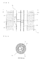
- Fig. 5 is a longitudinal sectional view of the connection portion of the aluminum pipe and the copper pipe according to Embodiment of the present invention.
- Fig. 6 is a cross-sectional view (arrow sectional view taken along line A-A in Fig. 5 ) of the connection portion.
- Condensation cannot be completely prevented by covering the connection pipe unit 20 with the thermally insulating material 60 as described above.
- a small amount of water having condensed stays in a small space 70 ( Figs. 5 and 6 ) between the thermally insulating material 60 and the connection pipe unit 20.
- the water having condensed and staying in the small space 70 covers surfaces of the aluminum pipes 31 and 41 and the copper pipes 32 and 42 in a continuous manner.
- copper ions Cu2+ of the copper pipes 32 and 42 diffuse toward the aluminum pipes 31 and 41 against gravity through the water having condensed and staying, thereby causing electrolytic corrosion (galvanic corrosion) of aluminum or an aluminum alloy to occur.
- a zinc diffusion layer is formed on the surface of each of the aluminum pipes 31 and 41 so that corrosion of the aluminum pipes 31 and 41 can be suppressed.
- progress of corrosion of the aluminum pipes 31 and 41 formed of aluminum or an aluminum alloy can be suppressed, and accordingly, reliability of measures against leakage of the refrigerant can be improved. It is desirable that formation of the zinc diffusion layer on the surfaces of the aluminum pipes 31 and 41 formed of aluminum or an aluminum alloy be performed on original pipes of the aluminum pipes 31 and 41.
- the heat shrinkable tubes or coatings attached or applied to the connection portions 37 and 47 may be applied or attached entirely to ranges of the aluminum pipes 31 and 41, the ranges being covered by the thermally insulating material 60, in order to prevent water from adhering to the connection portions 37 and 47.
- the heat shrinkable tubes are attached or coatings be applied to the aluminum pipes 31 and 41 while the aluminum pipes 31 and 41 are still connection pipes in an assembled state before being brazed to the heat transfer pipes 12 and 16 of the indoor heat exchanger 10.
- the aluminum pipes 31 and 41 may be anodized or plated with metal such as zinc or manganese. Also in this case, it is desirable that the aluminum pipes 31 and 41 be anodized or plated while the aluminum pipe 31 and 41 are connection pipes in an assembled state before being brazed to the heat transfer pipes 12 and 16 of the indoor heat exchanger 10.
- a clad material which is formed of a core material and a high corrosion-resistant aluminum alloy (for example, A7072) superposed on the core material, may be used for the aluminum pipes 31 and 41 as the material to which the anti-corrosion treatment is applied.
- A7072 high corrosion-resistant aluminum alloy
- an example of the heat exchanger according to the present invention is installed in the indoor unit 100.
- the heat exchanger according to the present invention may be installed in the outdoor unit 101. That is, in above-described Embodiment, an example of the heat exchanger according to the present invention is used as the indoor heat exchanger 10. However, it is clear that the heat exchanger according to the present invention may be used as an outdoor heat exchanger.
- an example of the cylindrical heat transfer pipes 12 and the flat heat transfer pipes 16 are used in the indoor heat exchanger 10.
- the indoor heat exchanger 10 may use either the heat transfer pipes 12 or the heat transfer pipes 16.
- an example of the heat exchanger includes fin-tube heat exchangers.
- the present invention is applicable to a variety of heat exchangers. That is, the present invention can be implemented by connecting the gas pipe 30 and the liquid pipe 40, which have been described in Embodiment of the present invention, to a heat exchanger equipped with heat transfer pipes formed of aluminum or an aluminum alloy.
Abstract
Description
- The present invention relates to a heat exchanger and an air-conditioning apparatus equipped with the heat exchanger.
- Heat exchangers equipped with heat exchangers having heat transfer pipes formed of aluminum or an aluminum alloy (hereafter, referred to as "aluminum heat exchanger") are known. The heat transfer pipes formed of aluminum or an aluminum alloy (or refrigerant pipes formed of aluminum or an aluminum alloy and connected to the heat transfer pipes. These pipes are referred to as "aluminum pipes" hereafter) of such a heat exchanger are connected to refrigerant pipes formed of copper or a copper alloy (hereafter, referred to as "copper pipes"), thereby incorporating the heat exchanger in a refrigeration cycle. In the case where the aluminum heat exchanger is incorporated in the refrigeration cycle using the copper pipes in the above-described manner, when water staying on the copper pipes adheres to the heat transfer pipes or the aluminum pipes, there arises a problem in that electrolytic corrosion (galvanic corrosion) occurs in the heat transfer pipes or the aluminum pipes.
- For this reason, technologies for heat exchangers have been proposed so as to prevent electrolytic corrosion (galvanic corrosion) in the heat transfer pipes formed of aluminum or aluminum alloys and aluminum pipes from occurring. Such a technology has been proposed, for example, as follows: "An air-conditioning apparatus includes a main body of the air-conditioning apparatus, a compressor, and a securing member that secures a refrigeration cycle unit to the main body of the air-conditioning apparatus. The refrigeration cycle unit includes a heat exchanger formed of aluminum or an aluminum alloy and a refrigerant pipe, which is formed of copper or a copper alloy and connected to the heat exchanger. An entire portion of the refrigerant pipe above the heat exchanger serves as a water droplet prevention pipe portion, which is inclined downward from the heat exchanger toward the refrigerant pipe, so that water droplets flow downward along the refrigerant pipe, thereby preventing electrolytic corrosion of the heat exchanger due to copper ions from occurring" (see, for example, Patent Literature 1).
- [Patent Literature 1] Japanese Unexamined Patent Application Publication No.
6-300303 Fig. 1 ) - In an air-conditioning apparatus (for example, an indoor unit) equipped with a related-art aluminum heat exchanger, in order to prevent water droplets having condensed on connection pipes (including connection unit in which the aluminum side and the copper side are connected to each other) for the aluminum heat exchanger from leaking to the outside of the air-conditioning apparatus, the connection pipes need to be covered with a thermally insulating material so as to suppress condensation. However, condensation cannot be completely prevented even by covering the connection pipes with the thermally insulating material, and accordingly, a small amount of water having condensed on the connection pipes stays in a small gap between the thermally insulating material and the connection pipes. Thus, copper ions on the side of the connection pipes being formed of copper or a copper alloy diffuse toward the side of the connection pipes formed of aluminum or an aluminum alloy through water, which has condensed and stays. As a result, there arises a problem in that electrolytic corrosion (galvanic corrosion) occurs in the connection pipes formed of aluminum or an aluminum alloy.
- The present invention is proposed in order to solve the above-described problem. An object of the present invention is to provide a heat exchanger and an air-conditioning apparatus including the heat exchanger, in which progress of electrolytic corrosion (galvanic corrosion) of aluminum or an aluminum alloy can be suppressed. Electrolytic corrosion (galvanic corrosion) of aluminum or an aluminum alloy is caused by diffusion of copper ions to connection pipes formed of aluminum or an aluminum alloy through water having condensed and staying in a small gap between the thermally insulating material and the connection pipe unit.
- A heat exchanger according to the present invention includes a heat transfer pipe formed of aluminum or an aluminum alloy; and a connection pipe unit through which a refrigerant flowing out of the heat transfer pipe and a refrigerant flowing into the heat transfer pipe pass, the connection pipe unit including a gas pipe through which the refrigerant in a gaseous state flows, and a liquid pipe through which the refrigerant in a liquid state or in a two-phase gas-liquid state flows, the gas pipe and the liquid pipe each having a first refrigerant pipe formed of aluminum or an aluminum alloy, and a second refrigerant pipe formed of copper or a copper alloy, the first refrigerant pipe and the second refrigerant pipe being connected to each other, the first refrigerant pipe having a fall portion connected to the heat transfer pipe, the fall portion extending downward relative to the heat transfer pipe. In the heat exchanger, each connection portion between the first refrigerant pipe and the second refrigerant pipe is disposed in the fall portion of the first refrigerant pipe, the connection pipe unit is covered with a thermally insulating material, and anti-corrosion treatment is applied to each first refrigerant pipe covered with the thermally insulating material.
- An air-conditioning apparatus according to the present invention includes the heat exchanger.
- In the heat exchanger according to the present invention, in each of the gas pipe and the liquid pipe of the connection pipe unit, the connection portion, in which the first refrigerant pipe (refrigerant pipe formed of aluminum or an aluminum alloy) and the second refrigerant pipe (refrigerant pipe formed of copper or a copper alloy) are connected to each other, is disposed in the fall portion of the first refrigerant pipe. The connection pipe unit is covered with the thermally insulating material, and anti-corrosion treatment is applied to the first refrigerant pipe (a refrigerant pipe formed of aluminum or an aluminum alloy) covered with the thermally insulating material. Thus, even when condensation occurs in the connection pipe unit covered with the thermally insulating material and water having condensed stays in a small gap between the thermally insulating material and the connection pipe unit, progress of corrosion of the first refrigerant pipe (a refrigerant pipe formed of aluminum or an aluminum alloy) can be suppressed, and accordingly, the heat exchanger can have a long life.
- Since the air-conditioning apparatus according to the present invention includes the heat exchanger, progress of corrosion of the first refrigerant pipe (a refrigerant pipe formed of aluminum or an aluminum alloy) can be suppressed, and accordingly, the air-conditioning apparatus can have a long life.
-
-
Fig. 1 is an explanatory diagram illustrating a state in which an air-conditioning apparatus according to Embodiment of the present invention is installed. -
Fig. 2 includes perspective views of a heat exchanger according to Embodiment of the present invention. -
Fig. 3 is an enlarged front view of the main part of the heat exchanger according to Embodiment of the present invention. -
Fig. 4 is a side view of the heat exchanger according to Embodiment of the present invention. -
Fig. 5 is a longitudinal sectional view of a connection portion, in which an aluminum pipe and a copper pipe are connected to each other, according to Embodiment of the present invention. -
Fig. 6 is a cross-sectional view (arrow sectional view taken along line A-A inFig. 5 ) of the connection portion, in which the aluminum pipe and the copper pipe are connected to each other, according to Embodiment of the present invention. -
Fig. 7 is a sectional view of a state in which the aluminum pipe and a copper pipe according to Embodiment of the present invention are connected to each other. - In Embodiment below, a heat exchanger according to the present invention installed in an indoor unit of an air-conditioning apparatus will be described. An example of the indoor unit according to the present invention is a wall-mounting indoor unit.
-
Fig. 1 is an explanatory diagram illustrating a state in which the air-conditioning apparatus according to Embodiment of the present invention is installed.
As illustrated inFig. 1 , the air-conditioning apparatus according to Embodiment of the present invention includes anindoor unit 100 and anoutdoor unit 101. Theindoor unit 100 is mounted on awall 111 of a conditionedspace 110. Theoutdoor unit 101 is installed outside the conditionedspace 110. - The
indoor unit 100 includes components such as ahousing 1, a fan 5, and anindoor heat exchanger 10. Thehousing 1 has, for example, a substantially rectangular box shape and has anair inlet 2 formed on an upper portion thereof and anair outlet 3 formed on a lower portion thereof. Theair inlet 2 is provided with afilter 2a, which collects dust and the like from indoor air sucked into thehousing 1. Theair outlet 3 is provided with a wind direction adjustment mechanism 4, which adjust directions of conditioned air being blown through theair outlet 3. - The fan 5 includes, for example, a cross flow fan disposed in the
housing 1. Theindoor heat exchanger 10 is disposed so as to cover a front, top, and rear sides of the fan 5. - The
indoor heat exchanger 10 according to Embodiment of the present invention includes fin-tube heat exchangers. Theindoor heat exchanger 10 includes a plurality ofheat exchangers 10a and a plurality ofheat exchangers 10b. Theheat exchangers 10a include cylindricalheat transfer pipes 12. Theheat exchangers 10b include flatheat transfer pipes 16. Eachheat exchanger 10a includes a plurality offins 11 and the plurality of heat transfer pipes (cylindrical pipes) 12. Thefins 11 are formed of aluminum or an aluminum alloy. Theheat transfer pipes 12 are formed of aluminum or an aluminum alloy. Thefins 11 are stacked so as to be spaced apart from one another by a specified gap. The heat transfer pipes (cylindrical pipes) 12 extend through the stackedfins 11. Eachheat exchanger 10b includes a plurality offins 15 and the plurality of heat transfer pipes (flat pipes) 16. Thefins 15 are formed of aluminum or an aluminum alloy. Theheat transfer pipes 16 are formed of aluminum or an aluminum alloy. Thefins 15 are stacked so as to be spaced apart from one another by a specified gap. The heat transfer pipes (flat pipes) 16 extend through the stackedfins 15. - When the fan 5 is driven, room air in the conditioned
space 110 is sucked into thehousing 1 through theair inlet 2. The room air is heated or cooled into conditioned air while flowing through theindoor heat exchanger 10. The conditioned air is blown through theair outlet 3. In theindoor heat exchanger 10 according to Embodiment of the present invention, theheat exchangers 10a using the cylindricalheat transfer pipes 12 are located upstream in an air flow direction, and theheat exchangers 10b using the flatheat transfer pipes 16 are located downstream in the air flow direction. Theindoor heat exchanger 10 has a capability of having a plurality of independent refrigerant circuits, so that theindoor heat exchanger 10 can be thermally divided into, for example, two sections (for example, a section of theheat exchangers 10a and a section of theheat exchangers 10b). A pressure reducing device for reheat dehumidification 8 (for example, an expansion valve:Fig. 2 ) is connected between thermally divided two sections of heat exchangers. This can cause, while, for example, cooling operation is being performed, part of theindoor heat exchanger 10 to function as a condenser and part of the remaining part of theindoor heat exchanger 10 to function as an evaporator. Thus, by thermally dividing theindoor heat exchanger 10 into two sections, when dehumidification is performed during cooling operation, the temperature of the conditioned air to be blown through theair outlet 3 can be prevented from being excessively decreased. - The
indoor heat exchanger 10 includesconnection pipe unit 20. An end of theconnection pipe unit 20 is connected to the heat transfer pipes (connected to either theheat transfer pipes 12 or theheat transfer pipes 16, or theheat transfer pipes 12 and 16) of theindoor heat exchanger 10. Theconnection pipe unit 20 is formed of copper or a copper alloy and is routed to the outdoor side through ahole 112 formed in thewall 111. A flare nut connection unit 29 is provided at the other end of theconnection pipe unit 20. By connecting the flare nut connection unit 29 to a flarenut connection unit 51 of anextended pipe unit 50, which is connected to theoutdoor unit 101, theindoor unit 100 is connected to theoutdoor unit 101. That is, by connecting the flare nut connection unit 29 to the flarenut connection unit 51, theindoor heat exchanger 10 is connected to elements of a refrigeration cycle (such as an outdoor heat exchanger and a compressor, both of which are not shown), the elements being provided in theoutdoor unit 101, thereby forming the refrigeration cycle. - As will be described later, the
connection pipe unit 20 includes two pipes (agas pipe 30 and a liquid pipe 40). In order to accommodate these, the flare nut connection unit 29 includes two flare nut connection sub-units (a flare nut connection sub-unit 39 for thegas pipe 30 and a flare nut connection sub-unit 49 for the liquid pipe 40). Accordingly, theextended pipe unit 50 also includes two pipes and the flarenut connection unit 51 of theextended pipe unit 50 includes two flare nut connection sub-units. - Next, the details of the
connection pipe unit 20 will be described. -
Fig. 2 includes perspective views of the heat exchanger according to Embodiment of the present invention.Fig. 3 is an enlarged front view of the main part of the heat exchanger.Fig. 4 is a side view of the heat exchanger. AlthoughFig. 2 includes separate views (a) and (b) for description of thegas pipe 30 and theliquid pipe 40, the views (a) and (b) are the same except for reference numerals. The details of theconnection pipe unit 20 according to Embodiment of the present invention will be described below with reference toFigs. 2 to 4 . - The
connection pipe unit 20 includes thegas pipe 30 and and theliquid pipe 40. - The
gas pipe 30 is a refrigerant pipe through which mainly the refrigerant in a gaseous state flows. Thus, when cooling operation is being performed (when theindoor heat exchanger 10 functions as an evaporator), the refrigerant having flowed through theheat transfer pipes indoor heat exchanger 10 flows out of theindoor unit 100 through thegas pipe 30. In contrast, when heating operation is being performed (when theindoor heat exchanger 10 functions as an condenser), the refrigerant to flow through theheat transfer pipes indoor heat exchanger 10 flows into theindoor unit 100 through thegas pipe 30. - The
liquid pipe 40 is a refrigerant pipe through which mainly the refrigerant in a liquid state flows. Thus, when cooling operation is being performed (when theindoor heat exchanger 10 functions as an evaporator), the refrigerant to flow through theheat transfer pipes indoor heat exchanger 10 flows into theindoor unit 100 through theliquid pipe 40. In contrast, when heating operation is being performed (when theindoor heat exchanger 10 functions as an condenser), the refrigerant having flowed through theheat transfer pipes indoor heat exchanger 10 flows out of theindoor unit 100 through theliquid pipe 40. The refrigerant having flowed through a pressure reducing device, which is an element of the refrigeration cycle, may flow through theliquid pipe 40 depending on the configuration of the refrigeration cycle. In this case, the refrigerant flowing through theliquid pipe 40 is a liquid-rich two-phase gas-liquid refrigerant. - In the heat exchanger according to Embodiment of the present invention, the
gas pipe 30 is made of analuminum pipe 31 formed of aluminum or an aluminum alloy and acopper pipe 32 formed of copper or a copper alloy. Likewise, theliquid pipe 40 is made of analuminum pipe 41 formed of aluminum or an aluminum alloy and acopper pipe 42 formed of copper or a copper alloy. Thealuminum pipes copper pipes gas pipe 30 and theliquid pipe 40 having the above-described structure is as follows. - In general, in the flare
nut connection units 29 and 51 connecting theextended pipe unit 50 to thegas pipe 30 and theliquid pipe 40, pipes on one side of connection (for example, the pipes of the extended pipe unit 50) each have an internal thread portion, and pipes on the other side of the connection (for example, thegas pipe 30 and the liquid pipe 40) each have an external thread portion. Each internal thread portion has an internal thread formed in an inner surface thereof and a through hole communicating with a space in which the internal thread is formed. At the end of a pipe unit on the one side of the connection (for example, the extended pipe unit 50), each pipe is inserted through the through hole while the diameter of the end of the pipe is enlarged by forming a flare. The external thread portion is brazed to the end of each pipe on the other side of the connection (for example, thegas pipe 30 and the liquid pipe 40). The external thread portions and the respective internal thread portions are screwed to each other. Thus, each end of the pipes at which the flares is formed (for example, the pipe of the extended pipe unit 50) on the one side of the connection is firmly held between the corresponding one of the internal thread portions and the corresponding one of the external thread portions. Thus, theextended pipe unit 50 is connected to thegas pipe 30 and theliquid pipe 40. In general, the external and the internal thread portions are formed of brass with consideration of, for example, suitability of the material for brazing and workability. - Here, in the case where, for example, the
gas pipe 30 is formed only of thealuminum pipe 31 and the flare nut connection sub-unit 39 of thegas pipe 30 has the brass external thread portion, it is difficult for the flare nut connection sub-unit 39 to be brazed to thealuminum pipe 31. Also in this case, metal materials of thealuminum pipe 31 and the flare nut connection sub-unit 39 are different from each other, and accordingly, electrolytic corrosion (galvanic corrosion) as described later occurs in a portion where thealuminum pipe 31 and the flare nut connection sub-unit 39 are connected to each other. For example, in the case where thegas pipe 30 is formed only of thealuminum pipe 31 and the flare nut connection sub-unit 39 of thegas pipe 30 has the brass internal thread portion, metal materials of thealuminum pipe 31 and the flare nut connection sub-unit 39 are different from each other, and accordingly, electrolytic corrosion (galvanic corrosion) as described later occurs in a portion where thealuminum pipe 31 and the flare nut connection sub-unit 39 are in contact with each other. - For example, in the case where the
gas pipe 30 is formed only of thealuminum pipe 31 and the flare nut connection sub-unit 39 of thegas pipe 30 has the external thread portion formed of aluminum or an aluminum alloy, the strength of the screw thread of the flare nut connection sub-unit 39 is insufficient. Also in this case, since the flarenut connection unit 51 of the copper extendedpipe unit 50 has the brass internal thread portions, electrolytic corrosion (galvanic corrosion) as described later occurs between the flare nut connection sub-unit 39 of thegas pipe 30 and the flarenut connection unit 51 of theextended pipe unit 50. - For example, in the case where the
gas pipe 30 is formed only of thealuminum pipe 31 and the flare nut connection sub-unit 39 of thegas pipe 30 has the internal thread portion formed of aluminum or an aluminum alloy, the strength of the screw thread of the flare nut connection sub-unit 39 is insufficient. Furthermore, when forming a flare at an end of thealuminum pipe 31, there is a concern that the end of thealuminum pipe 31 may crack. Since the flarenut connection unit 51 of the copper extendedpipe unit 50 has the brass external thread portions, electrolytic corrosion (galvanic corrosion) as described later occurs between the flare nut connection sub-unit 39 of thegas pipe 30 and the flarenut connection unit 51 of theextended pipe unit 50. - For example, in the case where the
gas pipe 30 is formed only of thealuminum pipe 31 and the flare nut connection sub-unit 39 of thegas pipe 30 and the flarenut connection unit 51 of theextended pipe unit 50 are formed of aluminum or an aluminum alloy, the strengths of the screw threads of the flare nut connection sub-unit 39 and the flarenut connection unit 51 are insufficient. In the case where the flare nut connection sub-unit 39 of thegas pipe 30 has the internal thread portion, when forming the flare at the end of thealuminum pipe 31, there is a concern that the end of thealuminum pipe 31 may crack. Furthermore, in order to prevent electrolytic corrosion (galvanic corrosion) as described later from occurring in a portion where theextended pipe unit 50 and the flarenut connection unit 51 are connected to each other, the pipes of theextended pipe unit 50 need to be formed of aluminum or an aluminum alloy. For this reason, in the case where the flarenut connection unit 51 of theextended pipe unit 50 has the internal thread portions, when forming the flares at the end of the pipes of theextended pipe unit 50, there is a concern that the end of the pipes of theextended pipe unit 50 may crack. - Thus, in the heat exchanger according to Embodiment of the present invention, the
gas pipe 30 is formed of thealuminum pipe 31 and thecopper pipe 32. In thegas pipe 30, the brass flare nut connection sub-unit 39 having an internal or external thread portion is provided at an end of thecopper pipe 32, thereby preventing the strength of the screw thread from becoming insufficient and the end of the pipe from cracking, which might otherwise occur when the flare is formed. Likewise, theliquid pipe 40 is formed of thealuminum pipe 41 and thecopper pipe 42, and the brass flare nut connection sub-unit 49 having an internal or external thread portion is provided at an end of thecopper pipe 42, thereby preventing the strength of the screw thread from becoming insufficient and the end of the pipe from cracking, which might otherwise occur when the flare is formed. - Here, in the heat exchanger according to Embodiment of the present invention, the
aluminum pipe 31 and thecopper pipe 32 are connected to each other at aconnection portion 37 by eutectic bonding (bonding in which metals are contacted with each other at a certain temperature so as to form a eutectic alloy). The end of thealuminum pipe 31 opposite to theconnection portion 37 is connected to one of theheat transfer pipes 12 or one of theheat transfer pipes 16 by, for example, brazing. Likewise, thealuminum pipe 41 and thecopper pipe 42 are connected to each other at aconnection portion 47 by eutectic bonding (bonding in which metals are contacted with each other at a certain temperature so as to form a eutectic alloy). The end of thealuminum pipe 41 opposite to theconnection portion 47 is connected to one of theheat transfer pipes 12 or one of theheat transfer pipes 16 by, for example, brazing. - In particular, the
connection portion 37, in which thealuminum pipe 31 and thecopper pipe 32 are connected to each other, and theconnection portion 47, in which thealuminum pipe 41 and thecopper pipe 42 are connected to each other, have a structure as illustrated inFig. 7 . That is, the ends of thecopper pipes aluminum pipes connection portions aluminum pipes copper pipes connection portions 37 and 47 (in particular, parts of theconnection portions connection portions connection portions - In the air-conditioning apparatus according to Embodiment of the present invention, as illustrated in
Fig. 1 , when theindoor unit 100 is installed, the connection pipe unit 20 (gas pipe 30 and the liquid pipe 40) is routed to the outdoor side through thehole 112 formed in thewall 111. In so doing, the position of thehole 112 of thewall 111 and an installation position of theindoor unit 100 change in accordance with the installation environment. Thus, lowercurved portions curved portions curved portions - In Embodiment, the
aluminum pipe 31 of φ9.52 mm x t1.0 mm and thecopper pipe 32 of φ9.52 mm x t0.8 mm are connected to each other so as to form thegas pipe 30, and thealuminum pipe 41 of φ7.00 mm x t0.75 mm and thecopper pipe 42 of φ7.00 mm x t0.60 mm are connected to each other so as to form theliquid pipe 40. - Also in Embodiment, in order to prevent electrolytic corrosion (galvanic corrosion) of the
aluminum pipes gas pipe 30 and theliquid pipe 40 are formed to have the following shapes. - When water including copper ions (Cu2+) is in contact with aluminum or an aluminum alloy, aluminum or the aluminum alloy undergoes the following reaction due to the difference in ionization tendency:
2Al + 3Cu2+ → 2Al3+ + 3Cu.
That is, aluminum is ionized, and accordingly, electrolytic corrosion (galvanic corrosion) of aluminum or an aluminum alloy occurs. - In contrast, adhesion of water droplets including aluminum ions (Al3+) to aluminum or an aluminum alloy does not cause electrolytic corrosion (galvanic corrosion) of aluminum or an aluminum alloy, because the water including aluminum ions is composed of the same atom as aluminum or an aluminum alloy. When water droplets including aluminum ions (Al3+) adhere to copper or a copper alloy, ionization tendency of copper is smaller than that of aluminum, and accordingly, electrolytic corrosion (galvanic corrosion) of copper or a copper alloy does not occur.
- The
gas pipe 30 and theliquid pipe 40 in between uppercurved portions heat transfer pipes indoor heat exchanger 10 are inclined such that droplets of water having condensed flow toward theindoor heat exchanger 10. Thus, when theconnection portions heat transfer pipes indoor heat exchanger 10 than the uppercurved portions indoor heat exchanger 10. This causes electrolytic corrosion (galvanic corrosion) to occur in portions of thegas pipe 30 and theliquid pipe 40, the portions being formed of aluminum or an aluminum alloy, and theheat transfer pipes indoor heat exchanger 10 formed of aluminum or an aluminum alloy. - Thus, in Embodiment, the
connection portion 37 is disposed in alinear portion 35, which is in a substantially vertical portion of thegas pipe 30, such that an upper part of thelinear portion 35 is to be thealuminum pipe 31 and the lower part of thelinear portion 35 of thegas pipe 30 is to be thecopper pipe 32. - Likewise, the
connection portion 47 is disposed in alinear portion 45, which is in a substantially vertical portion of theliquid pipe 40, such that an upper part of thelinear portion 45 is to be thealuminum pipe 41 and the lower part of thelinear portion 45 of theliquid pipe 40 is to be thecopper pipe 42. - That is, the
connection portions curved portions linear portions fall portions
Although thefall portions fall portions - The
connection portion 37 of thegas pipe 30 and theconnection portion 47 of theliquid pipe 40 are desirably located at the same height level because, in many cases, thegas pipe 30 and theliquid pipe 40 are disposed so as to be close to each other. By locating theconnection portion 37 of thegas pipe 30 and theconnection portion 47 of theliquid pipe 40 at the same height level, a situation in which electrolytic corrosion (galvanic corrosion) occurs in thealuminum pipe 41 of theliquid pipe 40 due to contact of thealuminum pipe 41 of theliquid pipe 40 with thecopper pipe 32 of thegas pipe 30 can be prevented from occurring. Furthermore, a situation in which electrolytic corrosion (galvanic corrosion) occurs in thealuminum pipe 31 of thegas pipe 30 due to contact of thealuminum pipe 31 of thegas pipe 30 with thecopper pipe 42 of theliquid pipe 40 can be also prevented from occurring. - In Embodiment, condensation is suppressed by covering the
connection pipe unit 20 with a thermally insulatingmaterial 60 in order to prevent leakage of water droplets having condensed on theconnection pipe unit 20 to the outside of the air-conditioning apparatus. -
Fig. 5 is a longitudinal sectional view of the connection portion of the aluminum pipe and the copper pipe according to Embodiment of the present invention.Fig. 6 is a cross-sectional view (arrow sectional view taken along line A-A inFig. 5 ) of the connection portion.
Condensation cannot be completely prevented by covering theconnection pipe unit 20 with the thermally insulatingmaterial 60 as described above. Thus, a small amount of water having condensed stays in a small space 70 (Figs. 5 and 6 ) between the thermally insulatingmaterial 60 and theconnection pipe unit 20. The water having condensed and staying in thesmall space 70 covers surfaces of thealuminum pipes copper pipes copper pipes aluminum pipes - According to Embodiment, even when copper ions Cu2+ of the
copper pipes aluminum pipes small space 70, a zinc diffusion layer is formed on the surface of each of thealuminum pipes aluminum pipes aluminum pipes
It is desirable that formation of the zinc diffusion layer on the surfaces of thealuminum pipes aluminum pipes - Alternatively, as an anti-corrosion treatment of the
aluminum pipes connection portions aluminum pipes material 60, in order to prevent water from adhering to theconnection portions aluminum pipes aluminum pipes heat transfer pipes indoor heat exchanger 10. - Alternatively, as the anti-corrosion treatment of the
aluminum pipes aluminum pipes aluminum pipes aluminum pipe heat transfer pipes indoor heat exchanger 10. - Alternatively, a clad material, which is formed of a core material and a high corrosion-resistant aluminum alloy (for example, A7072) superposed on the core material, may be used for the
aluminum pipes - In above-described Embodiment, an example of the heat exchanger according to the present invention is installed in the
indoor unit 100. However, it is clear that the heat exchanger according to the present invention may be installed in theoutdoor unit 101. That is, in above-described Embodiment, an example of the heat exchanger according to the present invention is used as theindoor heat exchanger 10. However, it is clear that the heat exchanger according to the present invention may be used as an outdoor heat exchanger. - In above-described Embodiment, an example of the cylindrical
heat transfer pipes 12 and the flatheat transfer pipes 16 are used in theindoor heat exchanger 10. However, theindoor heat exchanger 10 may use either theheat transfer pipes 12 or theheat transfer pipes 16. - In above-described Embodiment, an example of the heat exchanger (indoor heat exchanger 10) includes fin-tube heat exchangers. However, it is clear that the present invention is applicable to a variety of heat exchangers. That is, the present invention can be implemented by connecting the
gas pipe 30 and theliquid pipe 40, which have been described in Embodiment of the present invention, to a heat exchanger equipped with heat transfer pipes formed of aluminum or an aluminum alloy. - 1 housing, 2 air inlet, 2a filter, 3 air outlet, 4 wind direction adjustment mechanism, 5 fan, 8 pressure reducing device for reheat dehumidification, 10 indoor heat exchanger, 10a, 10b heat exchanger, 11 fin, 12 heat transfer pipe (cylindrical), 15 fin, 16 heat transfer pipe (flat), 20 connection pipe unit, 29, 51 flare nut connection unit, 30 gas pipe, 31, 41 aluminum pipe (first refrigerant pipe), 32, 42 copper pipe (second refrigerant pipe), 33, 43 fall portion, 34, 44 upper curved portion, 35, 45 linear portion, 36, 46 lower curved portion, 37, 47 connection portion, 39, 49 flare nut connection sub-unit, 40 liquid pipe, 50 extended pipe unit, 60 thermally insulating material, 70 small space, 100 indoor unit, 101 outdoor unit, 110 conditioned space, 111 wall, and 112 hole.
Claims (4)
- A heat exchanger (10) comprising:a heat transfer pipe (12, 16) formed of aluminum or an aluminum alloy; anda connection pipe unit (20) through which a refrigerant flowing out of the heat transfer pipe (12, 16) and a refrigerant flowing into the heat transfer pipe (12, 16) pass,the connection pipe unit (20) includinga gas pipe (30) through which the refrigerant in a gaseous state flows, anda liquid pipe (40) through which the refrigerant in a liquid state or in a two-phase gas-liquid state flows,the gas pipe (30) and the liquid pipe (40) each havinga first refrigerant pipe (31, 41) formed of aluminum or an aluminum alloy, anda second refrigerant pipe (32, 42) formed of copper or a copper alloy,the first refrigerant pipe (31, 41) and the second refrigerant pipe (32, 42) being connected to each other,the first refrigerant pipe (31, 41) having a fall portion (33, 43) connected to the heat transfer pipe (12, 16), the fall portion (33, 43) extending downward relative to the heat transfer pipe (12, 16), whereineach connection portion (37, 47) between the first refrigerant pipe (31, 41) and the second refrigerant pipe (32, 42) is disposed in the fall portion (33, 43) of the first refrigerant pipe (31, 41),the connection pipe unit (20) is covered with a thermally insulating material (60), andanti-corrosion treatment is applied to each first refrigerant pipe (31, 41) covered with the thermally insulating material (60).
- The heat exchanger (10) of Claim 1, wherein
the gas pipe (30) and the liquid pipe (40) each have a curved portion (36, 46) in a lower part of the fall portion (33, 43) of the first refrigerant pipe (31, 41), and
each connection portion (37, 47) is located above the corresponding curved portions (36, 46). - The heat exchanger (10) of Claim 1 or 2, wherein
the connection portion (37) of the gas pipe (30) and the connection portion (47) of the liquid pipe (40) are located at a same height level. - An air-conditioning apparatus comprising:the heat exchanger (10) of any one of Claims 1 to 3.
Applications Claiming Priority (1)
| Application Number | Priority Date | Filing Date | Title |
|---|---|---|---|
| JP2012014875A JP5881435B2 (en) | 2012-01-27 | 2012-01-27 | Heat exchanger and air conditioner equipped with the same |
Publications (3)
| Publication Number | Publication Date |
|---|---|
| EP2620736A2 true EP2620736A2 (en) | 2013-07-31 |
| EP2620736A3 EP2620736A3 (en) | 2018-03-14 |
| EP2620736B1 EP2620736B1 (en) | 2019-10-23 |
Family
ID=46799116
Family Applications (1)
| Application Number | Title | Priority Date | Filing Date |
|---|---|---|---|
| EP12182717.4A Active EP2620736B1 (en) | 2012-01-27 | 2012-09-03 | Heat exchanger and air-conditioning apparatus having the same |
Country Status (7)
| Country | Link |
|---|---|
| EP (1) | EP2620736B1 (en) |
| JP (1) | JP5881435B2 (en) |
| CN (1) | CN103225847A (en) |
| ES (1) | ES2756774T3 (en) |
| MY (1) | MY166580A (en) |
| RU (1) | RU2509969C1 (en) |
| SG (1) | SG192323A1 (en) |
Cited By (17)
| Publication number | Priority date | Publication date | Assignee | Title |
|---|---|---|---|---|
| EP3101353A1 (en) * | 2014-01-30 | 2016-12-07 | Daikin Industries, Ltd. | Air conditioner indoor unit |
| EP3705792A4 (en) * | 2018-12-25 | 2020-09-09 | GD Midea Air-Conditioning Equipment Co., Ltd. | Air conditioner indoor unit and air conditioner |
| WO2021064442A1 (en) * | 2019-09-30 | 2021-04-08 | Daikin Industries (Thailand) Ltd. | Indoor unit for an air conditioner |
| US20210231343A1 (en) * | 2017-12-05 | 2021-07-29 | Daikin Industries, Ltd. | Air conditioner |
| US11365335B2 (en) | 2017-12-18 | 2022-06-21 | Daikin Industries, Ltd. | Composition comprising refrigerant, use thereof, refrigerating machine having same, and method for operating said refrigerating machine |
| US11435118B2 (en) | 2017-12-18 | 2022-09-06 | Daikin Industries, Ltd. | Heat source unit and refrigeration cycle apparatus |
| US11441802B2 (en) | 2017-12-18 | 2022-09-13 | Daikin Industries, Ltd. | Air conditioning apparatus |
| US11441819B2 (en) | 2017-12-18 | 2022-09-13 | Daikin Industries, Ltd. | Refrigeration cycle apparatus |
| US11466891B2 (en) | 2018-12-25 | 2022-10-11 | Gd Midea Air-Conditioning Equipment Co., Ltd. | Air conditioner indoor unit and air conditioner |
| US11493244B2 (en) | 2017-12-18 | 2022-11-08 | Daikin Industries, Ltd. | Air-conditioning unit |
| US11492527B2 (en) | 2017-12-18 | 2022-11-08 | Daikin Industries, Ltd. | Composition containing refrigerant, use of said composition, refrigerator having said composition, and method for operating said refrigerator |
| US11506425B2 (en) | 2017-12-18 | 2022-11-22 | Daikin Industries, Ltd. | Refrigeration cycle apparatus |
| US11535781B2 (en) | 2017-12-18 | 2022-12-27 | Daikin Industries, Ltd. | Refrigeration cycle apparatus |
| US11549695B2 (en) | 2017-12-18 | 2023-01-10 | Daikin Industries, Ltd. | Heat exchange unit |
| US11549041B2 (en) | 2017-12-18 | 2023-01-10 | Daikin Industries, Ltd. | Composition containing refrigerant, use of said composition, refrigerator having said composition, and method for operating said refrigerator |
| US11820933B2 (en) | 2017-12-18 | 2023-11-21 | Daikin Industries, Ltd. | Refrigeration cycle apparatus |
| US11906207B2 (en) | 2017-12-18 | 2024-02-20 | Daikin Industries, Ltd. | Refrigeration apparatus |
Families Citing this family (11)
| Publication number | Priority date | Publication date | Assignee | Title |
|---|---|---|---|---|
| JP6079619B2 (en) * | 2013-12-27 | 2017-02-15 | ダイキン工業株式会社 | Air conditioning indoor unit |
| JP6452961B2 (en) * | 2014-06-05 | 2019-01-16 | 日立ジョンソンコントロールズ空調株式会社 | Air conditioner |
| CN104390393A (en) * | 2014-10-29 | 2015-03-04 | 珠海格力电器股份有限公司 | Heat exchanger and air conditioner comprising heat exchanger |
| WO2017081735A1 (en) * | 2015-11-09 | 2017-05-18 | 三菱電機株式会社 | Refrigeration cycle device and refrigerant leak detection method |
| JP6719394B2 (en) * | 2017-01-16 | 2020-07-08 | 日立ジョンソンコントロールズ空調株式会社 | Connection piping structure of heat exchanger and air conditioner |
| WO2019123897A1 (en) * | 2017-12-18 | 2019-06-27 | ダイキン工業株式会社 | Refrigeration cycle device |
| WO2021186491A1 (en) * | 2020-03-16 | 2021-09-23 | 三菱電機株式会社 | Heat exchanger, air conditioner, and method for manufacturing heat exchanger |
| JP7410418B2 (en) * | 2021-09-30 | 2024-01-10 | ダイキン工業株式会社 | Indoor unit and air conditioner |
| JP2023051205A (en) * | 2021-09-30 | 2023-04-11 | ダイキン工業株式会社 | Indoor machine and air conditioner |
| JP7133076B1 (en) | 2021-09-30 | 2022-09-07 | ダイキン工業株式会社 | Heat exchange units and air conditioners |
| JP2024047966A (en) * | 2022-09-27 | 2024-04-08 | ダイキン工業株式会社 | Air conditioning unit |
Citations (1)
| Publication number | Priority date | Publication date | Assignee | Title |
|---|---|---|---|---|
| JPH06300303A (en) | 1993-04-15 | 1994-10-28 | Sanyo Electric Co Ltd | Air conditioner |
Family Cites Families (13)
| Publication number | Priority date | Publication date | Assignee | Title |
|---|---|---|---|---|
| JPH081348B2 (en) * | 1987-02-09 | 1996-01-10 | 三洋電機株式会社 | Cooling system |
| JPH04359797A (en) * | 1991-06-05 | 1992-12-14 | Showa Alum Corp | Heat exchanger |
| JPH09133389A (en) * | 1995-11-08 | 1997-05-20 | Sanyo Electric Co Ltd | Air conditioner |
| JP3197251B2 (en) * | 1998-09-22 | 2001-08-13 | カルソニックカンセイ株式会社 | Sacrificial corrosion-resistant aluminum alloys for heat exchangers and high corrosion-resistant aluminum alloy composites for heat exchangers |
| JP4474781B2 (en) * | 2001-03-19 | 2010-06-09 | 株式会社富士通ゼネラル | Air conditioner |
| TWI280340B (en) * | 2002-02-20 | 2007-05-01 | Showa Denko Kk | Heat exchanger with receiver tank, receiver tank connecting member, receiver tank mounting structure of heat exchanger and refrigeration system |
| JP2005055081A (en) * | 2003-08-05 | 2005-03-03 | Matsushita Electric Ind Co Ltd | Heat exchanger and vending machine provided with the heat exchanger |
| JP2005090761A (en) * | 2003-09-12 | 2005-04-07 | Matsushita Electric Ind Co Ltd | Air conditioner |
| JP2009092274A (en) * | 2007-10-05 | 2009-04-30 | Hitachi Appliances Inc | Air conditioner |
| CN201110733Y (en) * | 2007-10-26 | 2008-09-03 | 浙江亚技联节能设备有限公司 | Copper and aluminum composite tube shell type heat exchanger |
| CN201964811U (en) * | 2010-09-07 | 2011-09-07 | 万建红 | Separated flexible normal pressure heat pipe heat exchanger |
| CZ21751U1 (en) * | 2010-10-08 | 2011-02-14 | Lloyd Coils Europe, S.R.O. | Permanent joint ofcooling circuit copper and aluminium tubes |
| CN201983654U (en) * | 2011-02-10 | 2011-09-21 | 广东万和新电气股份有限公司 | Copper-aluminum heat exchanger of gas heater |
-
2012
- 2012-01-27 JP JP2012014875A patent/JP5881435B2/en active Active
- 2012-08-30 SG SG2012064432A patent/SG192323A1/en unknown
- 2012-09-03 EP EP12182717.4A patent/EP2620736B1/en active Active
- 2012-09-03 ES ES12182717T patent/ES2756774T3/en active Active
- 2012-09-18 MY MYPI2012004114A patent/MY166580A/en unknown
- 2012-09-19 RU RU2012140170/06A patent/RU2509969C1/en active
- 2012-09-20 CN CN2012103516484A patent/CN103225847A/en active Pending
Patent Citations (1)
| Publication number | Priority date | Publication date | Assignee | Title |
|---|---|---|---|---|
| JPH06300303A (en) | 1993-04-15 | 1994-10-28 | Sanyo Electric Co Ltd | Air conditioner |
Cited By (19)
| Publication number | Priority date | Publication date | Assignee | Title |
|---|---|---|---|---|
| EP3101353A4 (en) * | 2014-01-30 | 2017-05-17 | Daikin Industries, Ltd. | Air conditioner indoor unit |
| EP3101353A1 (en) * | 2014-01-30 | 2016-12-07 | Daikin Industries, Ltd. | Air conditioner indoor unit |
| US20210231343A1 (en) * | 2017-12-05 | 2021-07-29 | Daikin Industries, Ltd. | Air conditioner |
| EP3722686A4 (en) * | 2017-12-05 | 2021-08-25 | Daikin Industries, Ltd. | Air conditioner |
| US11441802B2 (en) | 2017-12-18 | 2022-09-13 | Daikin Industries, Ltd. | Air conditioning apparatus |
| US11535781B2 (en) | 2017-12-18 | 2022-12-27 | Daikin Industries, Ltd. | Refrigeration cycle apparatus |
| US11365335B2 (en) | 2017-12-18 | 2022-06-21 | Daikin Industries, Ltd. | Composition comprising refrigerant, use thereof, refrigerating machine having same, and method for operating said refrigerating machine |
| US11435118B2 (en) | 2017-12-18 | 2022-09-06 | Daikin Industries, Ltd. | Heat source unit and refrigeration cycle apparatus |
| US11906207B2 (en) | 2017-12-18 | 2024-02-20 | Daikin Industries, Ltd. | Refrigeration apparatus |
| US11441819B2 (en) | 2017-12-18 | 2022-09-13 | Daikin Industries, Ltd. | Refrigeration cycle apparatus |
| US11820933B2 (en) | 2017-12-18 | 2023-11-21 | Daikin Industries, Ltd. | Refrigeration cycle apparatus |
| US11493244B2 (en) | 2017-12-18 | 2022-11-08 | Daikin Industries, Ltd. | Air-conditioning unit |
| US11492527B2 (en) | 2017-12-18 | 2022-11-08 | Daikin Industries, Ltd. | Composition containing refrigerant, use of said composition, refrigerator having said composition, and method for operating said refrigerator |
| US11506425B2 (en) | 2017-12-18 | 2022-11-22 | Daikin Industries, Ltd. | Refrigeration cycle apparatus |
| US11549041B2 (en) | 2017-12-18 | 2023-01-10 | Daikin Industries, Ltd. | Composition containing refrigerant, use of said composition, refrigerator having said composition, and method for operating said refrigerator |
| US11549695B2 (en) | 2017-12-18 | 2023-01-10 | Daikin Industries, Ltd. | Heat exchange unit |
| US11466891B2 (en) | 2018-12-25 | 2022-10-11 | Gd Midea Air-Conditioning Equipment Co., Ltd. | Air conditioner indoor unit and air conditioner |
| EP3705792A4 (en) * | 2018-12-25 | 2020-09-09 | GD Midea Air-Conditioning Equipment Co., Ltd. | Air conditioner indoor unit and air conditioner |
| WO2021064442A1 (en) * | 2019-09-30 | 2021-04-08 | Daikin Industries (Thailand) Ltd. | Indoor unit for an air conditioner |
Also Published As
| Publication number | Publication date |
|---|---|
| JP5881435B2 (en) | 2016-03-09 |
| ES2756774T3 (en) | 2020-04-27 |
| EP2620736B1 (en) | 2019-10-23 |
| SG192323A1 (en) | 2013-08-30 |
| MY166580A (en) | 2018-07-17 |
| JP2013155892A (en) | 2013-08-15 |
| RU2509969C1 (en) | 2014-03-20 |
| CN103225847A (en) | 2013-07-31 |
| EP2620736A3 (en) | 2018-03-14 |
Similar Documents
| Publication | Publication Date | Title |
|---|---|---|
| EP2620736B1 (en) | Heat exchanger and air-conditioning apparatus having the same | |
| EP2423609B1 (en) | Heat exchanger and air conditioner on which this heat exchanger is mounted | |
| CN104011470B (en) | The outdoor unit of refrigerating plant | |
| EP2863159B1 (en) | Heat exchanger, method for producing same, and refrigeration cycle device | |
| US20110042047A1 (en) | Heat exchanger drip tube | |
| CN104024745A (en) | Outdoor unit for refrigeration apparatus | |
| JP6074648B2 (en) | Tube member assembly and heat exchanger of refrigeration cycle apparatus | |
| US11698213B2 (en) | Heat exchanger, indoor unit for air-conditioner, and refrigeration device | |
| JP2005133966A (en) | Heat exchanger | |
| JP2017133814A (en) | Heat exchanger | |
| CN107270589B (en) | Heat exchanger and household appliance | |
| WO2014199514A1 (en) | Outdoor unit for air conditioner and production method for outdoor unit for air conditioner | |
| EP3249339B1 (en) | Air conditioning device | |
| JP2018009742A (en) | Heat exchanger of refrigeration cycle device | |
| JP6873252B2 (en) | Heat exchanger, outdoor unit of air conditioner and air conditioner | |
| JP2018115804A (en) | Heat exchanger and outdoor unit for air conditioner | |
| AU2016210490B2 (en) | Heat exchanger and method of manufacturing same | |
| CN115127382A (en) | Heat exchanger and refrigeration cycle device |
Legal Events
| Date | Code | Title | Description |
|---|---|---|---|
| PUAI | Public reference made under article 153(3) epc to a published international application that has entered the european phase |
Free format text: ORIGINAL CODE: 0009012 |
|
| AK | Designated contracting states |
Kind code of ref document: A2 Designated state(s): AL AT BE BG CH CY CZ DE DK EE ES FI FR GB GR HR HU IE IS IT LI LT LU LV MC MK MT NL NO PL PT RO RS SE SI SK SM TR |
|
| AX | Request for extension of the european patent |
Extension state: BA ME |
|
| PUAL | Search report despatched |
Free format text: ORIGINAL CODE: 0009013 |
|
| AK | Designated contracting states |
Kind code of ref document: A3 Designated state(s): AL AT BE BG CH CY CZ DE DK EE ES FI FR GB GR HR HU IE IS IT LI LT LU LV MC MK MT NL NO PL PT RO RS SE SI SK SM TR |
|
| AX | Request for extension of the european patent |
Extension state: BA ME |
|
| RIC1 | Information provided on ipc code assigned before grant |
Ipc: F24F 13/30 20060101ALI20180206BHEP Ipc: F28F 9/02 20060101AFI20180206BHEP Ipc: F28F 19/02 20060101ALI20180206BHEP Ipc: F28F 19/00 20060101ALI20180206BHEP Ipc: F28F 21/08 20060101ALI20180206BHEP |
|
| STAA | Information on the status of an ep patent application or granted ep patent |
Free format text: STATUS: REQUEST FOR EXAMINATION WAS MADE |
|
| 17P | Request for examination filed |
Effective date: 20180822 |
|
| RBV | Designated contracting states (corrected) |
Designated state(s): AL AT BE BG CH CY CZ DE DK EE ES FI FR GB GR HR HU IE IS IT LI LT LU LV MC MK MT NL NO PL PT RO RS SE SI SK SM TR |
|
| GRAP | Despatch of communication of intention to grant a patent |
Free format text: ORIGINAL CODE: EPIDOSNIGR1 |
|
| STAA | Information on the status of an ep patent application or granted ep patent |
Free format text: STATUS: GRANT OF PATENT IS INTENDED |
|
| INTG | Intention to grant announced |
Effective date: 20190417 |
|
| GRAS | Grant fee paid |
Free format text: ORIGINAL CODE: EPIDOSNIGR3 |
|
| GRAA | (expected) grant |
Free format text: ORIGINAL CODE: 0009210 |
|
| STAA | Information on the status of an ep patent application or granted ep patent |
Free format text: STATUS: THE PATENT HAS BEEN GRANTED |
|
| AK | Designated contracting states |
Kind code of ref document: B1 Designated state(s): AL AT BE BG CH CY CZ DE DK EE ES FI FR GB GR HR HU IE IS IT LI LT LU LV MC MK MT NL NO PL PT RO RS SE SI SK SM TR |
|
| REG | Reference to a national code |
Ref country code: GB Ref legal event code: FG4D |
|
| REG | Reference to a national code |
Ref country code: CH Ref legal event code: EP |
|
| REG | Reference to a national code |
Ref country code: IE Ref legal event code: FG4D |
|
| REG | Reference to a national code |
Ref country code: DE Ref legal event code: R096 Ref document number: 602012065033 Country of ref document: DE |
|
| REG | Reference to a national code |
Ref country code: AT Ref legal event code: REF Ref document number: 1194118 Country of ref document: AT Kind code of ref document: T Effective date: 20191115 |
|
| REG | Reference to a national code |
Ref country code: NL Ref legal event code: MP Effective date: 20191023 |
|
| REG | Reference to a national code |
Ref country code: LT Ref legal event code: MG4D |
|
| REG | Reference to a national code |
Ref country code: ES Ref legal event code: FG2A Ref document number: 2756774 Country of ref document: ES Kind code of ref document: T3 Effective date: 20200427 |
|
| PG25 | Lapsed in a contracting state [announced via postgrant information from national office to epo] |
Ref country code: PT Free format text: LAPSE BECAUSE OF FAILURE TO SUBMIT A TRANSLATION OF THE DESCRIPTION OR TO PAY THE FEE WITHIN THE PRESCRIBED TIME-LIMIT Effective date: 20200224 Ref country code: GR Free format text: LAPSE BECAUSE OF FAILURE TO SUBMIT A TRANSLATION OF THE DESCRIPTION OR TO PAY THE FEE WITHIN THE PRESCRIBED TIME-LIMIT Effective date: 20200124 Ref country code: LT Free format text: LAPSE BECAUSE OF FAILURE TO SUBMIT A TRANSLATION OF THE DESCRIPTION OR TO PAY THE FEE WITHIN THE PRESCRIBED TIME-LIMIT Effective date: 20191023 Ref country code: NO Free format text: LAPSE BECAUSE OF FAILURE TO SUBMIT A TRANSLATION OF THE DESCRIPTION OR TO PAY THE FEE WITHIN THE PRESCRIBED TIME-LIMIT Effective date: 20200123 Ref country code: PL Free format text: LAPSE BECAUSE OF FAILURE TO SUBMIT A TRANSLATION OF THE DESCRIPTION OR TO PAY THE FEE WITHIN THE PRESCRIBED TIME-LIMIT Effective date: 20191023 Ref country code: SE Free format text: LAPSE BECAUSE OF FAILURE TO SUBMIT A TRANSLATION OF THE DESCRIPTION OR TO PAY THE FEE WITHIN THE PRESCRIBED TIME-LIMIT Effective date: 20191023 Ref country code: NL Free format text: LAPSE BECAUSE OF FAILURE TO SUBMIT A TRANSLATION OF THE DESCRIPTION OR TO PAY THE FEE WITHIN THE PRESCRIBED TIME-LIMIT Effective date: 20191023 Ref country code: LV Free format text: LAPSE BECAUSE OF FAILURE TO SUBMIT A TRANSLATION OF THE DESCRIPTION OR TO PAY THE FEE WITHIN THE PRESCRIBED TIME-LIMIT Effective date: 20191023 Ref country code: BG Free format text: LAPSE BECAUSE OF FAILURE TO SUBMIT A TRANSLATION OF THE DESCRIPTION OR TO PAY THE FEE WITHIN THE PRESCRIBED TIME-LIMIT Effective date: 20200123 Ref country code: FI Free format text: LAPSE BECAUSE OF FAILURE TO SUBMIT A TRANSLATION OF THE DESCRIPTION OR TO PAY THE FEE WITHIN THE PRESCRIBED TIME-LIMIT Effective date: 20191023 |
|
| PG25 | Lapsed in a contracting state [announced via postgrant information from national office to epo] |
Ref country code: IS Free format text: LAPSE BECAUSE OF FAILURE TO SUBMIT A TRANSLATION OF THE DESCRIPTION OR TO PAY THE FEE WITHIN THE PRESCRIBED TIME-LIMIT Effective date: 20200224 Ref country code: RS Free format text: LAPSE BECAUSE OF FAILURE TO SUBMIT A TRANSLATION OF THE DESCRIPTION OR TO PAY THE FEE WITHIN THE PRESCRIBED TIME-LIMIT Effective date: 20191023 Ref country code: HR Free format text: LAPSE BECAUSE OF FAILURE TO SUBMIT A TRANSLATION OF THE DESCRIPTION OR TO PAY THE FEE WITHIN THE PRESCRIBED TIME-LIMIT Effective date: 20191023 |
|
| PG25 | Lapsed in a contracting state [announced via postgrant information from national office to epo] |
Ref country code: AL Free format text: LAPSE BECAUSE OF FAILURE TO SUBMIT A TRANSLATION OF THE DESCRIPTION OR TO PAY THE FEE WITHIN THE PRESCRIBED TIME-LIMIT Effective date: 20191023 |
|
| REG | Reference to a national code |
Ref country code: DE Ref legal event code: R097 Ref document number: 602012065033 Country of ref document: DE |
|
| PG2D | Information on lapse in contracting state deleted |
Ref country code: IS |
|
| PG25 | Lapsed in a contracting state [announced via postgrant information from national office to epo] |
Ref country code: DK Free format text: LAPSE BECAUSE OF FAILURE TO SUBMIT A TRANSLATION OF THE DESCRIPTION OR TO PAY THE FEE WITHIN THE PRESCRIBED TIME-LIMIT Effective date: 20191023 Ref country code: EE Free format text: LAPSE BECAUSE OF FAILURE TO SUBMIT A TRANSLATION OF THE DESCRIPTION OR TO PAY THE FEE WITHIN THE PRESCRIBED TIME-LIMIT Effective date: 20191023 Ref country code: CZ Free format text: LAPSE BECAUSE OF FAILURE TO SUBMIT A TRANSLATION OF THE DESCRIPTION OR TO PAY THE FEE WITHIN THE PRESCRIBED TIME-LIMIT Effective date: 20191023 Ref country code: RO Free format text: LAPSE BECAUSE OF FAILURE TO SUBMIT A TRANSLATION OF THE DESCRIPTION OR TO PAY THE FEE WITHIN THE PRESCRIBED TIME-LIMIT Effective date: 20191023 Ref country code: IS Free format text: LAPSE BECAUSE OF FAILURE TO SUBMIT A TRANSLATION OF THE DESCRIPTION OR TO PAY THE FEE WITHIN THE PRESCRIBED TIME-LIMIT Effective date: 20200223 |
|
| REG | Reference to a national code |
Ref country code: AT Ref legal event code: MK05 Ref document number: 1194118 Country of ref document: AT Kind code of ref document: T Effective date: 20191023 |
|
| PLBE | No opposition filed within time limit |
Free format text: ORIGINAL CODE: 0009261 |
|
| STAA | Information on the status of an ep patent application or granted ep patent |
Free format text: STATUS: NO OPPOSITION FILED WITHIN TIME LIMIT |
|
| PG25 | Lapsed in a contracting state [announced via postgrant information from national office to epo] |
Ref country code: SM Free format text: LAPSE BECAUSE OF FAILURE TO SUBMIT A TRANSLATION OF THE DESCRIPTION OR TO PAY THE FEE WITHIN THE PRESCRIBED TIME-LIMIT Effective date: 20191023 Ref country code: SK Free format text: LAPSE BECAUSE OF FAILURE TO SUBMIT A TRANSLATION OF THE DESCRIPTION OR TO PAY THE FEE WITHIN THE PRESCRIBED TIME-LIMIT Effective date: 20191023 |
|
| 26N | No opposition filed |
Effective date: 20200724 |
|
| PG25 | Lapsed in a contracting state [announced via postgrant information from national office to epo] |
Ref country code: SI Free format text: LAPSE BECAUSE OF FAILURE TO SUBMIT A TRANSLATION OF THE DESCRIPTION OR TO PAY THE FEE WITHIN THE PRESCRIBED TIME-LIMIT Effective date: 20191023 Ref country code: AT Free format text: LAPSE BECAUSE OF FAILURE TO SUBMIT A TRANSLATION OF THE DESCRIPTION OR TO PAY THE FEE WITHIN THE PRESCRIBED TIME-LIMIT Effective date: 20191023 |
|
| REG | Reference to a national code |
Ref country code: DE Ref legal event code: R119 Ref document number: 602012065033 Country of ref document: DE |
|
| PG25 | Lapsed in a contracting state [announced via postgrant information from national office to epo] |
Ref country code: MC Free format text: LAPSE BECAUSE OF FAILURE TO SUBMIT A TRANSLATION OF THE DESCRIPTION OR TO PAY THE FEE WITHIN THE PRESCRIBED TIME-LIMIT Effective date: 20191023 |
|
| REG | Reference to a national code |
Ref country code: CH Ref legal event code: PL |
|
| GBPC | Gb: european patent ceased through non-payment of renewal fee |
Effective date: 20200903 |
|
| REG | Reference to a national code |
Ref country code: BE Ref legal event code: MM Effective date: 20200930 |
|
| PG25 | Lapsed in a contracting state [announced via postgrant information from national office to epo] |
Ref country code: LU Free format text: LAPSE BECAUSE OF NON-PAYMENT OF DUE FEES Effective date: 20200903 |
|
| PG25 | Lapsed in a contracting state [announced via postgrant information from national office to epo] |
Ref country code: DE Free format text: LAPSE BECAUSE OF NON-PAYMENT OF DUE FEES Effective date: 20210401 |
|
| PG25 | Lapsed in a contracting state [announced via postgrant information from national office to epo] |
Ref country code: CH Free format text: LAPSE BECAUSE OF NON-PAYMENT OF DUE FEES Effective date: 20200930 Ref country code: BE Free format text: LAPSE BECAUSE OF NON-PAYMENT OF DUE FEES Effective date: 20200930 Ref country code: IE Free format text: LAPSE BECAUSE OF NON-PAYMENT OF DUE FEES Effective date: 20200903 Ref country code: GB Free format text: LAPSE BECAUSE OF NON-PAYMENT OF DUE FEES Effective date: 20200903 Ref country code: LI Free format text: LAPSE BECAUSE OF NON-PAYMENT OF DUE FEES Effective date: 20200930 |
|
| PG25 | Lapsed in a contracting state [announced via postgrant information from national office to epo] |
Ref country code: TR Free format text: LAPSE BECAUSE OF FAILURE TO SUBMIT A TRANSLATION OF THE DESCRIPTION OR TO PAY THE FEE WITHIN THE PRESCRIBED TIME-LIMIT Effective date: 20191023 Ref country code: MT Free format text: LAPSE BECAUSE OF FAILURE TO SUBMIT A TRANSLATION OF THE DESCRIPTION OR TO PAY THE FEE WITHIN THE PRESCRIBED TIME-LIMIT Effective date: 20191023 Ref country code: CY Free format text: LAPSE BECAUSE OF FAILURE TO SUBMIT A TRANSLATION OF THE DESCRIPTION OR TO PAY THE FEE WITHIN THE PRESCRIBED TIME-LIMIT Effective date: 20191023 |
|
| PG25 | Lapsed in a contracting state [announced via postgrant information from national office to epo] |
Ref country code: MK Free format text: LAPSE BECAUSE OF FAILURE TO SUBMIT A TRANSLATION OF THE DESCRIPTION OR TO PAY THE FEE WITHIN THE PRESCRIBED TIME-LIMIT Effective date: 20191023 |
|
| P01 | Opt-out of the competence of the unified patent court (upc) registered |
Effective date: 20230512 |
|
| PGFP | Annual fee paid to national office [announced via postgrant information from national office to epo] |
Ref country code: IT Payment date: 20230810 Year of fee payment: 12 |
|
| PGFP | Annual fee paid to national office [announced via postgrant information from national office to epo] |
Ref country code: FR Payment date: 20230808 Year of fee payment: 12 |
|
| PGFP | Annual fee paid to national office [announced via postgrant information from national office to epo] |
Ref country code: ES Payment date: 20231003 Year of fee payment: 12 |