EP2620679B1 - Valve arrangement of a commercial cooking device and commercial cooking device - Google Patents
Valve arrangement of a commercial cooking device and commercial cooking device Download PDFInfo
- Publication number
- EP2620679B1 EP2620679B1 EP13000382.5A EP13000382A EP2620679B1 EP 2620679 B1 EP2620679 B1 EP 2620679B1 EP 13000382 A EP13000382 A EP 13000382A EP 2620679 B1 EP2620679 B1 EP 2620679B1
- Authority
- EP
- European Patent Office
- Prior art keywords
- valve
- valve disc
- conduit
- valve seat
- cooking chamber
- Prior art date
- Legal status (The legal status is an assumption and is not a legal conclusion. Google has not performed a legal analysis and makes no representation as to the accuracy of the status listed.)
- Active
Links
Images




Classifications
-
- A—HUMAN NECESSITIES
- A47—FURNITURE; DOMESTIC ARTICLES OR APPLIANCES; COFFEE MILLS; SPICE MILLS; SUCTION CLEANERS IN GENERAL
- A47J—KITCHEN EQUIPMENT; COFFEE MILLS; SPICE MILLS; APPARATUS FOR MAKING BEVERAGES
- A47J27/00—Cooking-vessels
-
- F—MECHANICAL ENGINEERING; LIGHTING; HEATING; WEAPONS; BLASTING
- F24—HEATING; RANGES; VENTILATING
- F24C—DOMESTIC STOVES OR RANGES ; DETAILS OF DOMESTIC STOVES OR RANGES, OF GENERAL APPLICATION
- F24C15/00—Details
- F24C15/20—Removing cooking fumes
- F24C15/2007—Removing cooking fumes from oven cavities
-
- F—MECHANICAL ENGINEERING; LIGHTING; HEATING; WEAPONS; BLASTING
- F16—ENGINEERING ELEMENTS AND UNITS; GENERAL MEASURES FOR PRODUCING AND MAINTAINING EFFECTIVE FUNCTIONING OF MACHINES OR INSTALLATIONS; THERMAL INSULATION IN GENERAL
- F16K—VALVES; TAPS; COCKS; ACTUATING-FLOATS; DEVICES FOR VENTING OR AERATING
- F16K17/00—Safety valves; Equalising valves, e.g. pressure relief valves
- F16K17/02—Safety valves; Equalising valves, e.g. pressure relief valves opening on surplus pressure on one side; closing on insufficient pressure on one side
- F16K17/04—Safety valves; Equalising valves, e.g. pressure relief valves opening on surplus pressure on one side; closing on insufficient pressure on one side spring-loaded
- F16K17/048—Safety valves; Equalising valves, e.g. pressure relief valves opening on surplus pressure on one side; closing on insufficient pressure on one side spring-loaded combined with other safety valves, or with pressure control devices
-
- F—MECHANICAL ENGINEERING; LIGHTING; HEATING; WEAPONS; BLASTING
- F16—ENGINEERING ELEMENTS AND UNITS; GENERAL MEASURES FOR PRODUCING AND MAINTAINING EFFECTIVE FUNCTIONING OF MACHINES OR INSTALLATIONS; THERMAL INSULATION IN GENERAL
- F16K—VALVES; TAPS; COCKS; ACTUATING-FLOATS; DEVICES FOR VENTING OR AERATING
- F16K17/00—Safety valves; Equalising valves, e.g. pressure relief valves
- F16K17/18—Safety valves; Equalising valves, e.g. pressure relief valves opening on surplus pressure on either side
- F16K17/19—Equalising valves predominantly for tanks
- F16K17/196—Equalising valves predominantly for tanks spring-loaded
-
- F—MECHANICAL ENGINEERING; LIGHTING; HEATING; WEAPONS; BLASTING
- F16—ENGINEERING ELEMENTS AND UNITS; GENERAL MEASURES FOR PRODUCING AND MAINTAINING EFFECTIVE FUNCTIONING OF MACHINES OR INSTALLATIONS; THERMAL INSULATION IN GENERAL
- F16K—VALVES; TAPS; COCKS; ACTUATING-FLOATS; DEVICES FOR VENTING OR AERATING
- F16K31/00—Actuating devices; Operating means; Releasing devices
- F16K31/02—Actuating devices; Operating means; Releasing devices electric; magnetic
- F16K31/06—Actuating devices; Operating means; Releasing devices electric; magnetic using a magnet, e.g. diaphragm valves, cutting off by means of a liquid
- F16K31/0644—One-way valve
- F16K31/0655—Lift valves
-
- F—MECHANICAL ENGINEERING; LIGHTING; HEATING; WEAPONS; BLASTING
- F24—HEATING; RANGES; VENTILATING
- F24C—DOMESTIC STOVES OR RANGES ; DETAILS OF DOMESTIC STOVES OR RANGES, OF GENERAL APPLICATION
- F24C15/00—Details
- F24C15/32—Arrangements of ducts for hot gases, e.g. in or around baking ovens
- F24C15/322—Arrangements of ducts for hot gases, e.g. in or around baking ovens with forced circulation
- F24C15/327—Arrangements of ducts for hot gases, e.g. in or around baking ovens with forced circulation with air moisturising
-
- Y—GENERAL TAGGING OF NEW TECHNOLOGICAL DEVELOPMENTS; GENERAL TAGGING OF CROSS-SECTIONAL TECHNOLOGIES SPANNING OVER SEVERAL SECTIONS OF THE IPC; TECHNICAL SUBJECTS COVERED BY FORMER USPC CROSS-REFERENCE ART COLLECTIONS [XRACs] AND DIGESTS
- Y10—TECHNICAL SUBJECTS COVERED BY FORMER USPC
- Y10T—TECHNICAL SUBJECTS COVERED BY FORMER US CLASSIFICATION
- Y10T137/00—Fluid handling
- Y10T137/7722—Line condition change responsive valves
- Y10T137/7837—Direct response valves [i.e., check valve type]
- Y10T137/7904—Reciprocating valves
Definitions
- the present disclosure relates to a valve arrangement of a commercial cooking device, according to the preamble part of claim 1.
- a valve arrangement is known from US 2 351 874 A .
- a commercial cooking device comprises a cooking chamber enclosed by a door that can be opened and closed for providing access to the cooking chamber. If the door is opened during a cooking process, e.g., for loading or unloading food products, a pressure rise can occur when the door is closed as cold air streams into the cooking chamber and heats up and expands very quickly.
- a known valve arrangement comprises a housing that is connected to the cooking chamber via a first conduit. The interior of the housing of the valve arrangement is also connected to the atmosphere via a second conduit. A valve member that closes and opens the conduit leading to the cooking chamber is disposed in the housing. This valve member has the function of a pressure relief valve that is opened by the high pressure in the cooking chamber and opens the conduit and is closed and closes the conduit to the cooking chamber after the pressure is relieved.
- valve disc of the known valve arrangement that opens and closes the conduit to the cooking chamber has a relatively small cross-sectional area and the flow resistance of the known valve arrangement is relatively high.
- a valve disc is disposed in close relation to the conduit leading to the cooking device cooking chamber and is opened for allowing high pressure from the cooking chamber to escape by the influence of the high pressure in the cooking chamber which moves the valve disc away from the conduit.
- the valve disc is unable to move away from the associated conduit, because low pressure, or fresh air entering from the outside, cause the valve disc to seal more tightly against the conduit leading to the cooking chamber.
- valve disc In this latter situation, the valve disc must be moved away from the associated conduit using a solenoid acting upon a stem affixed to the valve disc. There is no spring associated with the stem, so that movement of the valve disc is accomplished only by action of the solenoid upon the stem, or by gravity returning the valve disc to its closed location in close relation to the conduit.
- the present disclosure provides a valve arrangement that is able to reduce the flow resistance so that its pressure control characteristics are improved.
- the present disclosure overcomes the shortcomings of the state of the art.
- the present disclosure provides for faster release of any high pressure or over pressure in the cooking chamber, and also provides for faster balancing of pressures between the atmosphere and the cooking chamber when the cooking chamber is in a low pressure or vacuum state.
- the present disclosure provides for automatic balancing of such a low pressure or vacuum situation in the cooking chamber.
- valve arrangement according to the present disclosure makes it possible to use a larger valve disc that, in conjunction with the enlarged discharge cross-section of the valve seat opening, results in the advantage of a lower flow resistance. This, in turn, enhances the dehumidification of the cooking chamber and improves the balance of any pressure differences between the cooking chamber and the atmosphere.
- a valve arrangement according to the preferred embodiment of the invention is disclosed in claim 1.
- valve arrangement of the present disclosure finds use in commercial cooking devices, in particular in those commercial cooking devices known as combi-steamers.
- Fig. 1 shows commercial cooking device 12, in particular a combi-steamer.
- Cooking device 12 comprises housing 13 with door 14 that can be opened and closed to expose interior of cooking device 12, i.e., cooking chamber 15, in order to load and unload food products into and out of cooking chamber 15.
- Fan wheel 17 is located within cooking chamber 15.
- Fan wheel 17 is driven by motor 16 and comprises fan blades 18 at rear side of fan wheel 17 in order to create a slight negative pressure behind fan wheel 17.
- cooking device 12 comprises control means 19 that is adapted to control all the components of cooking device 12, and valve arrangement 20.
- Valve arrangement 20 is connected to cooking chamber 15 by means of first conduit 8 and to atmosphere A by means of second conduit 9.
- Cooking chamber heater 21 is disposed next to fan wheel 17.
- Condenser 52 is connected with cooking chamber 15 via outlet 53.
- Condenser has water level 56 and drain 55 as well as air vent 54 leading from condenser 52 to atmosphere A. Drain 55 extends part way into condenser 52 to provide water level 56 inside condens
- Valve arrangement 20 of the example shown in Fig. 1 can be used for the purpose of active dehumidification of cooking chamber 15. So, upon opening valve arrangement 20, dry air can be sucked into cooking chamber 15 by means of the slight negative pressure created by fan blades 18 behind fan wheel 17. Thus, an air/vapour mixture can be guided via outlet 53, condenser 52 and air vent 54 to atmosphere A, providing a continuous flow of fluid between inlet 9 and outlet or air vent 54.
- valve arrangement 20 including its functioning for an active dehumidification, will be described in the following paragraphs.
- Figs. 2 to 4 show a first example of valve arrangement 20 in different switching positions.
- valve arrangement 20 comprises housing 7 including first conduit 8 and second conduit 9. Conduits 8 and 9, respectively, connect interior chamber 22 of housing 7 with cooking chamber 15 and atmosphere A.
- Valve arrangement 20 comprises, according to the example shown in Figs. 2 to 4 , valve seat 23 that is disposed within interior chamber 22 of housing 7.
- Valve seat 23 includes valve seat opening 24 cooperating with valve disc means 25.
- Valve disc means 25 is moveably mounted between a closed position in which valve disc means 25 is seated on valve seat opening 24, as can be seen from Fig. 2 .
- valve disc means 25 can be moved to an open position in which valve disc means 25 is disposed away from valve seat opening 24 (see Figs. 3 and 4 ).
- actuator 3 is provided that is either fixed to housing 7 or a suitable position of cooking device 12.
- actuator 3 can be, e.g., a solenoid cooperating with stem 29.
- valve seat opening 24 has discharge cross-section DCS 24 that is represented by a double arrow. Discharge cross-section DCS 24 is larger than discharge cross-section DCS 8 of first conduit 8, and discharge cross-section DCS 9 of second conduit 9.
- valve arrangement 20 of the present disclosure comprises, according to the examples of Figs. 2 to 4 , socket 26 that extends into interior chamber 22 of housing 7. As can be seen from Figs. 2 to 4 , socket 26 comprising valve seat opening 24 surrounds aperture 9' of second conduit 9, with aperture 9' opening into interior chamber 22.
- valve disc means 25 that comprises vacuum valve disc 1 that has at least one through-hole, preferably a plurality of through-holes that, according to the depicted example of Figs. 2 to 4 , are represented by through-holes 27 and 27'.
- valve disc means 25 also comprises pressure relief valve disc 5 that is disposed next to vacuum valve disc 1 and can be moved relative to valve disc 1.
- vacuum valve disc 1 has cross-sectional area CSA 1 that is larger than discharge cross-section DCS 24 of valve seat opening 24.
- pressure relief valve disc 5 has cross-sectional area CSA 5 that is smaller than discharge cross-section DCS 24 of valve seat opening 24.
- Vacuum valve disc 1 is biased into a rest position by means of spring 2B that surrounds first length 28 of stem 29.
- First length 28 of stem 29 extends from vacuum valve disc 1 to actuator 3, as can be seen from Figs. 2 to 4 .
- one end of spring 2B abuts vacuum valve disc 1 and other end of spring 2B abuts shoulder 7A of housing 7.
- Pressure relief valve disc 5 is biased into a closed position by second spring 2A that surrounds second length 30 of stem 29, with end 31 of spring 2A abutting pressure relief valve disc 5 and end 32 of spring 2A abutting stop plate 33 fixed to an end 34 of the second length 30.
- Figs. 2 and 3 show the closed position of pressure relief valve disc 5 blocking through-holes 27 and 27'.
- Fig. 2 depicts the closed position of valve disc means 25 in which vacuum valve disc 1 is seated on valve seat 23, thus closing valve seat opening 24. Pressure relief valve disc 5 is pressed downwards onto vacuum valve disc 1, thus closing and blocking through holes 27 and 27'.
- Fig. 3 shows the open position of valve disc means 25 in case of a high negative pressure within cooking chamber 15.
- valve disc means 25 is displaced and lowered by means of high negative pressure within cooking chamber 15, thus spacing vacuum valve disc 1 from valve seat 23 so that valve seat opening 24 is opened.
- a flow of fresh air (represented by arrows 11 in Fig. 3 ) can flow from atmosphere A through second conduit 9 into interior chamber 22, through first conduit 8 out of interior chamber 22 and into cooking chamber 15, thus balancing the pressures between atmosphere A and cooking chamber 15.
- Fig. 3 also shows the position of valve disc means 25 in case of an active dehumidification for which purpose actuator 3 is operated such that valve disc means 25 is lowered in order to open valve seat opening 24 allowing fresh air into cooking chamber 15.
- Fig. 4 shows a high pressure situation within cooking chamber 15.
- vacuum valve disc 1 is pressed onto valve seat 23 by means of spring 2B thus closing valve seat opening 24.
- Through holes 27 and 27' are opened such that flow of air 10 can proceed from cooking chamber 15 through conduit 8 into interior chamber 22 through through-holes 27 and 27' into second conduit 9 and to atmosphere A.
- Fig. 5A shows a second example of valve arrangement 20.
- all the features that correspond to the first example set forth in Figs. 2-4 are designated with the same reference numerals.
- valve arrangement 20 comprises valve seats 35 and 36 that are suitably disposed within housing 7.
- Each of valve seats 35 and 36 has associated valve seat opening 37 and 38, respectively, comprising associated discharge cross-sections DCS 37 and DCS 38 , respectively.
- Discharge cross-sections DCS 37 and DCS 38 are larger than discharge cross-sections DCS 8 of conduit 8 and DCS 9 of conduit 9.
- First valve seat opening 37 cooperates with vacuum valve disc 39 that is biased by spring 41 onto valve seat 35 thus closing valve seat opening 37.
- Valve seat opening 37 can be opened by high negative pressure in cooking chamber 15.
- this example comprises actuator 40 that cooperates with stem 48 fixed to vacuum valve disc 39.
- Actuator 40 can also be used for opening valve seat opening 37 for the purpose of dehumidification of cooking chamber 15.
- valve seat opening 37 can be opened by operating actuator 40.
- Second valve seat 36 comprises valve seat opening 38 that cooperates with pressure relief valve disc 42.
- Pressure relief valve disc 42 is moveably mounted on guide means 43 by means of stem 49 that is fixed to pressure relief valve disc 42.
- Guide means 43 can be fixed to housing 7 and comprises inner bore 51 that guides stem 49.
- pressure relief valve disc 42 will be lifted by the air flow out of cooking chamber 15 into interior chamber 22 so that valve seat opening 38 is opened and the air under high pressure can be vented via conduit 9 to atmosphere A.
- valve disc 39 In case of a vacuum or low pressure in cooking chamber 15, valve disc 39 will be lowered, thus opening valve seat opening 37 so that a flow of air from atmosphere A can flow through conduit 9 into interior chamber 22 and through conduit 8 into cooking chamber 15.
- Fig. 5B is essentially identical to Fig. 5A , except that actuator 40 and guide means 43 are effectively reversed.
- guide means can be simplified as well because inner bore 51 can be omitted, with spring 41 being sufficient to suitably guide stem 48 when valve disc 39 is displaced due to low pressure or vacuum in cooking chamber (15).
- Figs. 6 to 8 differs from the example of Fig. 5 by the provision of rocker lever 44 that is pivotally mounted within housing 7 and cooperating with vacuum valve disc 39 and pressure relief valve disc 42. All components and features that correspond to the example of Fig. 5 are designated with the same reference numerals so that reference can be made to the respective description of Fig. 5 .
- rocker lever 44 comprises first rocker arm 47 that is fixed to vacuum valve disc 39.
- Rocker lever 44 comprises second arm 46 that abuts an end face 50 of pressure relief valve disc 42.
- Bearing 45 is provided that pivotally supports rocker lever 44 within housing 7 to allow pivoting movement that can be seen in Figs. 6 and 7 .
- a high negative pressure within cooking chamber 15 moves vacuum valve disc 39 downwardly against the biasing force of spring 41 that results in a pivoting movement of rocker lever 44 so that rocker arm 46 lifts pressure relief disc 42 upwardly, as can be seen in Fig. 7 .
- This movement opens both valve seat openings 37 and 38 so that the full cross-sectional area is open for flow of air 11 from atmosphere A to cooking chamber 15 and through interior chamber 22.
- Fig. 8 shows the situation of an overpressure in cooking chamber 15.
- valve seat opening 37 is closed by vacuum valve disc 39 while the high pressure and flow of air 10 lifts pressure relief valve disc 42 upwardly, thus opening valve seat opening 38.
- the flow path is open from cooking chamber 15 to atmosphere via conduit 8, internal chamber 22 and conduit 9.
Landscapes
- Engineering & Computer Science (AREA)
- General Engineering & Computer Science (AREA)
- Mechanical Engineering (AREA)
- Chemical & Material Sciences (AREA)
- Combustion & Propulsion (AREA)
- Food Science & Technology (AREA)
- Lift Valve (AREA)
- Safety Valves (AREA)
- Cookers (AREA)
- Details Of Valves (AREA)
Description
- The present disclosure relates to a valve arrangement of a commercial cooking device, according to the preamble part of claim 1. Such a valve arrangement is known from
US 2 351 874 A . - A commercial cooking device comprises a cooking chamber enclosed by a door that can be opened and closed for providing access to the cooking chamber. If the door is opened during a cooking process, e.g., for loading or unloading food products, a pressure rise can occur when the door is closed as cold air streams into the cooking chamber and heats up and expands very quickly.
- In order to balance such a pressure rise, a known valve arrangement comprises a housing that is connected to the cooking chamber via a first conduit. The interior of the housing of the valve arrangement is also connected to the atmosphere via a second conduit. A valve member that closes and opens the conduit leading to the cooking chamber is disposed in the housing. This valve member has the function of a pressure relief valve that is opened by the high pressure in the cooking chamber and opens the conduit and is closed and closes the conduit to the cooking chamber after the pressure is relieved.
- The valve disc of the known valve arrangement that opens and closes the conduit to the cooking chamber has a relatively small cross-sectional area and the flow resistance of the known valve arrangement is relatively high. In this state of the art valve arrangement, a valve disc is disposed in close relation to the conduit leading to the cooking device cooking chamber and is opened for allowing high pressure from the cooking chamber to escape by the influence of the high pressure in the cooking chamber which moves the valve disc away from the conduit. In a situation where there is a low pressure or near vacuum in the cooking chamber, or where fresh air must be allowed to enter the cooking chamber such as during dehumidification, the valve disc is unable to move away from the associated conduit, because low pressure, or fresh air entering from the outside, cause the valve disc to seal more tightly against the conduit leading to the cooking chamber. In this latter situation, the valve disc must be moved away from the associated conduit using a solenoid acting upon a stem affixed to the valve disc. There is no spring associated with the stem, so that movement of the valve disc is accomplished only by action of the solenoid upon the stem, or by gravity returning the valve disc to its closed location in close relation to the conduit.
- The present disclosure provides a valve arrangement that is able to reduce the flow resistance so that its pressure control characteristics are improved. In particular, the present disclosure overcomes the shortcomings of the state of the art. The present disclosure provides for faster release of any high pressure or over pressure in the cooking chamber, and also provides for faster balancing of pressures between the atmosphere and the cooking chamber when the cooking chamber is in a low pressure or vacuum state. In addition, the present disclosure provides for automatic balancing of such a low pressure or vacuum situation in the cooking chamber.
- The valve arrangement according to the present disclosure makes it possible to use a larger valve disc that, in conjunction with the enlarged discharge cross-section of the valve seat opening, results in the advantage of a lower flow resistance. This, in turn, enhances the dehumidification of the cooking chamber and improves the balance of any pressure differences between the cooking chamber and the atmosphere.
- A valve arrangement according to the preferred embodiment of the invention is disclosed in claim 1.
- More particularly, the valve arrangement of the present disclosure finds use in commercial cooking devices, in particular in those commercial cooking devices known as combi-steamers.
- Further advantageous, features and details of the present disclosure will become apparent from the following description of the drawings, in which:
-
Fig. 1 shows a simplified depiction of a commercial cooking device in a highly simplified way, -
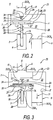
Figs. 2 to 4 are highly simplified depictions of a valve arrangement not forming part of the claimed invention, -
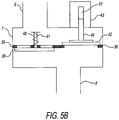
Fig. 5A and5B are highly simplified depiction of another valve arrangement not forming part of the claimed invention, and -
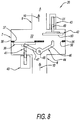
Figs. 6 to 8 are highly simplified depictions of an embodiment of the valve arrangement according to the present disclosure. -
Fig. 1 showscommercial cooking device 12, in particular a combi-steamer.Cooking device 12 compriseshousing 13 withdoor 14 that can be opened and closed to expose interior ofcooking device 12, i.e.,cooking chamber 15, in order to load and unload food products into and out ofcooking chamber 15.Fan wheel 17 is located withincooking chamber 15.Fan wheel 17 is driven bymotor 16 and comprisesfan blades 18 at rear side offan wheel 17 in order to create a slight negative pressure behindfan wheel 17. Finally,cooking device 12 comprises control means 19 that is adapted to control all the components ofcooking device 12, andvalve arrangement 20.Valve arrangement 20 is connected tocooking chamber 15 by means offirst conduit 8 and to atmosphere A by means ofsecond conduit 9.Cooking chamber heater 21 is disposed next tofan wheel 17.Condenser 52 is connected withcooking chamber 15 viaoutlet 53. Condenser haswater level 56 anddrain 55 as well asair vent 54 leading fromcondenser 52 to atmosphere A. Drain 55 extends part way intocondenser 52 to providewater level 56 insidecondenser 52. -
Valve arrangement 20 of the example shown inFig. 1 can be used for the purpose of active dehumidification ofcooking chamber 15. So, uponopening valve arrangement 20, dry air can be sucked intocooking chamber 15 by means of the slight negative pressure created byfan blades 18 behindfan wheel 17. Thus, an air/vapour mixture can be guided viaoutlet 53,condenser 52 andair vent 54 to atmosphere A, providing a continuous flow of fluid betweeninlet 9 and outlet orair vent 54. - Embodiments and details of
valve arrangement 20, including its functioning for an active dehumidification, will be described in the following paragraphs. -
Figs. 2 to 4 show a first example ofvalve arrangement 20 in different switching positions. - As can be seen from
Figs. 2 to 4 ,valve arrangement 20 compriseshousing 7 includingfirst conduit 8 andsecond conduit 9.Conduits interior chamber 22 ofhousing 7 withcooking chamber 15 and atmosphere A. -
Valve arrangement 20 comprises, according to the example shown inFigs. 2 to 4 ,valve seat 23 that is disposed withininterior chamber 22 ofhousing 7.Valve seat 23 includes valve seat opening 24 cooperating with valve disc means 25. Valve disc means 25 is moveably mounted between a closed position in which valve disc means 25 is seated on valve seat opening 24, as can be seen fromFig. 2 . Moreover, valve disc means 25 can be moved to an open position in which valve disc means 25 is disposed away from valve seat opening 24 (seeFigs. 3 and4 ). - To move valve disc means 25,
actuator 3 is provided that is either fixed tohousing 7 or a suitable position ofcooking device 12. In the example shown inFigs. 2 to 4 ,actuator 3 can be, e.g., a solenoid cooperating withstem 29. - As can be best seen from
Fig. 3 showing a switching condition in which valve disc means 25 is separated from valve seat opening 24, valve seat opening 24 has discharge cross-section DCS24 that is represented by a double arrow. Discharge cross-section DCS24 is larger than discharge cross-section DCS8 offirst conduit 8, and discharge cross-section DCS9 ofsecond conduit 9. - In order to provide larger discharge cross-section DCS24 of valve seat opening 24,
valve arrangement 20 of the present disclosure comprises, according to the examples ofFigs. 2 to 4 ,socket 26 that extends intointerior chamber 22 ofhousing 7. As can be seen fromFigs. 2 to 4 ,socket 26 comprising valve seat opening 24surrounds aperture 9' ofsecond conduit 9, withaperture 9' opening intointerior chamber 22. - The example of
Figs. 2 to 4 includes valve disc means 25 that comprises vacuum valve disc 1 that has at least one through-hole, preferably a plurality of through-holes that, according to the depicted example ofFigs. 2 to 4 , are represented by through-holes 27 and 27'. - Moreover, valve disc means 25 also comprises pressure
relief valve disc 5 that is disposed next to vacuum valve disc 1 and can be moved relative to valve disc 1. - As can be seen from
Figs. 2 to 4 , vacuum valve disc 1 has cross-sectional area CSA1 that is larger than discharge cross-section DCS24 of valve seat opening 24. In turn, pressurerelief valve disc 5 has cross-sectional area CSA5 that is smaller than discharge cross-section DCS24 of valve seat opening 24. - Vacuum valve disc 1 is biased into a rest position by means of
spring 2B that surroundsfirst length 28 ofstem 29.First length 28 ofstem 29 extends from vacuum valve disc 1 toactuator 3, as can be seen fromFigs. 2 to 4 . - In order to be able to bias vacuum valve disc 1 into the closed position, one end of
spring 2B abuts vacuum valve disc 1 and other end ofspring 2B abutsshoulder 7A ofhousing 7. - Pressure
relief valve disc 5 is biased into a closed position bysecond spring 2A that surroundssecond length 30 ofstem 29, with end 31 ofspring 2A abutting pressurerelief valve disc 5 and end 32 ofspring 2A abutting stop plate 33 fixed to anend 34 of thesecond length 30. -
Figs. 2 and 3 show the closed position of pressurerelief valve disc 5 blocking through-holes 27 and 27'. -
Fig. 2 depicts the closed position of valve disc means 25 in which vacuum valve disc 1 is seated onvalve seat 23, thus closingvalve seat opening 24. Pressurerelief valve disc 5 is pressed downwards onto vacuum valve disc 1, thus closing and blocking throughholes 27 and 27'. -
Fig. 3 shows the open position of valve disc means 25 in case of a high negative pressure withincooking chamber 15. In this situation, valve disc means 25 is displaced and lowered by means of high negative pressure withincooking chamber 15, thus spacing vacuum valve disc 1 fromvalve seat 23 so thatvalve seat opening 24 is opened. A flow of fresh air (represented byarrows 11 inFig. 3 ) can flow from atmosphere A throughsecond conduit 9 intointerior chamber 22, throughfirst conduit 8 out ofinterior chamber 22 and intocooking chamber 15, thus balancing the pressures between atmosphere A andcooking chamber 15.Fig. 3 also shows the position of valve disc means 25 in case of an active dehumidification for whichpurpose actuator 3 is operated such that valve disc means 25 is lowered in order to openvalve seat opening 24 allowing fresh air intocooking chamber 15. -
Fig. 4 shows a high pressure situation within cookingchamber 15. In this situation, vacuum valve disc 1 is pressed ontovalve seat 23 by means ofspring 2B thus closingvalve seat opening 24. However, flow ofair 10 flowing from cookingchamber 15 intointerior chamber 22 ofhousing 7 and lifts pressurerelief valve disc 5 upwards against the force ofspring 2A. Throughholes 27 and 27' are opened such that flow ofair 10 can proceed from cookingchamber 15 throughconduit 8 intointerior chamber 22 through through-holes 27 and 27' intosecond conduit 9 and to atmosphere A. -
Fig. 5A shows a second example ofvalve arrangement 20. InFig. 5A , all the features that correspond to the first example set forth inFigs. 2-4 are designated with the same reference numerals. - As can be seen from
Fig. 5A , this example ofvalve arrangement 20 comprises valve seats 35 and 36 that are suitably disposed withinhousing 7. Each ofvalve seats valve seat opening conduit 8 and DCS9 ofconduit 9. - First
valve seat opening 37 cooperates withvacuum valve disc 39 that is biased byspring 41 ontovalve seat 35 thus closingvalve seat opening 37.Valve seat opening 37 can be opened by high negative pressure in cookingchamber 15. Also, this example comprisesactuator 40 that cooperates withstem 48 fixed tovacuum valve disc 39.Actuator 40 can also be used for openingvalve seat opening 37 for the purpose of dehumidification ofcooking chamber 15. For this purpose,valve seat opening 37 can be opened by operatingactuator 40. -
Second valve seat 36 comprisesvalve seat opening 38 that cooperates with pressurerelief valve disc 42. Pressurerelief valve disc 42 is moveably mounted on guide means 43 by means ofstem 49 that is fixed to pressurerelief valve disc 42. Guide means 43 can be fixed tohousing 7 and comprisesinner bore 51 that guidesstem 49. - If a high pressure is created in
cooking chamber 15, pressurerelief valve disc 42 will be lifted by the air flow out ofcooking chamber 15 intointerior chamber 22 so thatvalve seat opening 38 is opened and the air under high pressure can be vented viaconduit 9 to atmosphere A. - In case of a vacuum or low pressure in cooking
chamber 15,valve disc 39 will be lowered, thus openingvalve seat opening 37 so that a flow of air from atmosphere A can flow throughconduit 9 intointerior chamber 22 and throughconduit 8 intocooking chamber 15. -
Fig. 5B is essentially identical toFig. 5A , except thatactuator 40 and guide means 43 are effectively reversed. In the configuration ofFig. 5B , guide means can be simplified as well because inner bore 51 can be omitted, withspring 41 being sufficient to suitably guidestem 48 whenvalve disc 39 is displaced due to low pressure or vacuum in cooking chamber (15). - The embodiment according to
Figs. 6 to 8 differs from the example ofFig. 5 by the provision ofrocker lever 44 that is pivotally mounted withinhousing 7 and cooperating withvacuum valve disc 39 and pressurerelief valve disc 42. All components and features that correspond to the example ofFig. 5 are designated with the same reference numerals so that reference can be made to the respective description ofFig. 5 . - As can be seen from
Figs. 6 to 8 ,rocker lever 44 comprisesfirst rocker arm 47 that is fixed tovacuum valve disc 39.Rocker lever 44 comprisessecond arm 46 that abuts anend face 50 of pressurerelief valve disc 42.Bearing 45 is provided that pivotally supportsrocker lever 44 withinhousing 7 to allow pivoting movement that can be seen inFigs. 6 and 7 . - Also with this embodiment, a high negative pressure within
cooking chamber 15 movesvacuum valve disc 39 downwardly against the biasing force ofspring 41 that results in a pivoting movement ofrocker lever 44 so thatrocker arm 46 liftspressure relief disc 42 upwardly, as can be seen inFig. 7 . This movement opens bothvalve seat openings air 11 from atmosphere A tocooking chamber 15 and throughinterior chamber 22. -
Fig. 8 shows the situation of an overpressure in cookingchamber 15. In this case,valve seat opening 37 is closed byvacuum valve disc 39 while the high pressure and flow ofair 10 lifts pressurerelief valve disc 42 upwardly, thus openingvalve seat opening 38. In this manner, the flow path is open from cookingchamber 15 to atmosphere viaconduit 8,internal chamber 22 andconduit 9. - In the above detailed description, the specific embodiments of this disclosure have been described in connection with its preferred embodiments. However, to the extent that the above description is specific to a particular embodiment or a particular use of this disclosure, this is intended to be illustrative only and merely provides a concise description of the exemplary embodiments. Accordingly, the disclosure is not limited to the specific embodiments described above, but rather, the disclosure includes all alternatives, modifications, and equivalents falling within the true scope of the appended claims. Various modifications and variations of this disclosure will be obvious to a worker skilled in the art and it is to be understood that such modifications and variations are to be included within the purview of this application and the scope of the claims.
Claims (3)
- A valve arrangement (20) of a commercial cooking device (12) having a cooking chamber (15), said valve arrangement (20) comprising:a housing (7) having a first conduit (8) connecting an interior chamber (22) of the housing (7) with the cooking chamber (15) of the cooking device (12), the first conduit (8) having a first discharge cross-section (DCS8); a second conduit (9) connecting the interior chamber (22) of the housing (7) with an outer atmosphere (a), the second conduit (9) having a second discharge cross-section (DCS9); and at least one valve seat (23) disposed within the interior chamber (22) of the housing (7), and having at least one valve seat opening (24) cooperating with at least one valve disc (25), the at least one valve disc (25) moveable between a closed position in which the valve disc (25) is seated on the valve seat opening (24), and an open position in which the valve disc (25) is disposed away from the valve seat opening (24); wherein two valve seats (35, 36) are provided in the housing (7), each valve seat (35, 36) having a valve seat opening (37, 38) comprising a discharge cross-section (DCS37, DCS38) larger than the discharge cross-section (DCS8) of the first conduit (8), the second conduit (9), or both conduits (8, 9),wherein one valve seat opening (37) cooperates with a vacuum valve disc (39) that is adapted to be biased by a spring (41) to a closed position seated on the valve seat opening (37),and wherein one valve seat opening (38) cooperates with a pressure relief valve disc (42), the pressure relief valve disc (42) moveably mounted in a guide (43),characterized in thatthe vacuum valve disc (39) is adapted to be moved by an actuator (40) to an open position disposed away from the valve seat opening (37), andwherein a rocker lever (44) is pivotally mounted within the housing (7), the rocker lever (44) in cooperating relation with the vacuum valve disc (39) and the pressure relief valve disc (42).
- The valve arrangement (20) according to claim 1, wherein the rocker lever (44) comprises a first rocker arm (47) fixed to the vacuum valve disc (39) and a second rocker arm (46) abutting an end face (50) of the pressure relief valve disc (42).
- The valve arrangement (20) according to claim 1, further comprising an actuator (3, 40) for moving the at least one valve disc (25) between the open and closed position for the purpose of dehumidification of the cooking chamber (15).
Applications Claiming Priority (1)
| Application Number | Priority Date | Filing Date | Title |
|---|---|---|---|
| US201261591701P | 2012-01-27 | 2012-01-27 |
Publications (3)
| Publication Number | Publication Date |
|---|---|
| EP2620679A2 EP2620679A2 (en) | 2013-07-31 |
| EP2620679A3 EP2620679A3 (en) | 2016-09-28 |
| EP2620679B1 true EP2620679B1 (en) | 2019-04-24 |
Family
ID=47631247
Family Applications (1)
| Application Number | Title | Priority Date | Filing Date |
|---|---|---|---|
| EP13000382.5A Active EP2620679B1 (en) | 2012-01-27 | 2013-01-25 | Valve arrangement of a commercial cooking device and commercial cooking device |
Country Status (2)
| Country | Link |
|---|---|
| US (1) | US9326632B2 (en) |
| EP (1) | EP2620679B1 (en) |
Families Citing this family (8)
| Publication number | Priority date | Publication date | Assignee | Title |
|---|---|---|---|---|
| FR3027375A1 (en) * | 2014-10-21 | 2016-04-22 | Airindex | PRESSURE CONTROL DEVICE PARTICULARLY FOR WATER STORAGE TANK |
| DE102016204833B4 (en) | 2016-03-23 | 2017-11-16 | Convotherm-Elektrogeräte Gmbh | Commercial cooking appliance |
| DE102016215650A1 (en) * | 2016-08-19 | 2018-02-22 | BSH Hausgeräte GmbH | Haushaltsgargerät |
| DE102017220234A1 (en) | 2017-11-14 | 2019-05-16 | BSH Hausgeräte GmbH | Cooking device with specific steam discharge device |
| US10948068B2 (en) * | 2018-03-01 | 2021-03-16 | GM Global Technology Operations LLC | Transmission pressure controlled vent system |
| JP7053082B2 (en) * | 2018-06-07 | 2022-04-12 | イ、ヨンヒ | Cooking smoke exhaust device |
| CN112178250B (en) * | 2020-08-24 | 2024-10-25 | 林�发 | Balanced atmospheric pressure steam valve and container |
| WO2025247189A1 (en) * | 2024-05-31 | 2025-12-04 | 广东美的厨房电器制造有限公司 | Cooking appliance |
Family Cites Families (13)
| Publication number | Priority date | Publication date | Assignee | Title |
|---|---|---|---|---|
| US2351874A (en) * | 1942-05-20 | 1944-06-20 | Parker Appliance Co | Relief valve for fuel tanks |
| US2515229A (en) * | 1947-05-06 | 1950-07-18 | Domestic Thermostat Company | Combined manual, thermostatic, and safety valve unit in burner systems |
| GB832039A (en) * | 1957-01-30 | 1960-04-06 | Bataafsche Petroleum | A safety device for liquid storage tanks |
| GB921535A (en) * | 1961-01-09 | 1963-03-20 | William Warren Triggs C B E | Fluid flow control valves |
| US4872474A (en) * | 1988-10-14 | 1989-10-10 | Ore-Ida Vended Products, Inc. | Diverter valve |
| JP3243503B2 (en) * | 1991-12-12 | 2002-01-07 | 株式会社鷺宮製作所 | Proportional control valve |
| US5282492A (en) * | 1993-02-23 | 1994-02-01 | The United States Of America As Represented By The Secretary Of The Navy | Dual valve plate two-way pressure relief valve |
| US6213447B1 (en) * | 1999-07-29 | 2001-04-10 | Delphi Technologies, Inc. | Poppet value having a compliant shaft guide and compliant valve head |
| EP1423013A2 (en) * | 2001-09-07 | 2004-06-02 | Alto-Shaam, Inc. | Humidity control system for combination oven |
| JP3944706B2 (en) * | 2002-02-14 | 2007-07-18 | 株式会社ニフコ | 2-way valve |
| EP1954968B1 (en) * | 2005-12-01 | 2018-09-12 | BorgWarner, Inc. | Pressure compensating method |
| JP2008075827A (en) * | 2006-09-25 | 2008-04-03 | Denso Corp | Fluid control valve |
| DE102008012681B4 (en) * | 2008-03-05 | 2015-09-03 | Rational Ag | Cooking device with a ventilation valve |
-
2013
- 2013-01-24 US US13/749,340 patent/US9326632B2/en active Active
- 2013-01-25 EP EP13000382.5A patent/EP2620679B1/en active Active
Non-Patent Citations (1)
| Title |
|---|
| None * |
Also Published As
| Publication number | Publication date |
|---|---|
| US20130192473A1 (en) | 2013-08-01 |
| US9326632B2 (en) | 2016-05-03 |
| EP2620679A3 (en) | 2016-09-28 |
| EP2620679A2 (en) | 2013-07-31 |
Similar Documents
| Publication | Publication Date | Title |
|---|---|---|
| US9326632B2 (en) | Valve arrangement of a commercial cooking device and commercial cooking device | |
| US8944100B2 (en) | Isolation valve with fast depressurization for high-pressure fuel tank | |
| US9624875B2 (en) | Isolation valve with integrated float valve for high-pressure applications | |
| US20150144819A1 (en) | Isolation valve with fast depressurization for high-pressure fuel tank | |
| US8281803B2 (en) | Balanced port housing with integrated flow conditioning | |
| US20130074956A1 (en) | Pressure reducing apparatus | |
| US5479978A (en) | Pressure-vacuum relief valve assembly | |
| EP3153634B1 (en) | Minor water leak prevention apparatus for water inlet valve | |
| CN103140367B (en) | Safety valve and fuel vapor valve assembly | |
| EP1916461A2 (en) | Three position shutoff valve | |
| CA2478716A1 (en) | Priming apparatus for a centrifugal pump | |
| CN105658923B (en) | Actuator for the valve gear in internal combustion engine | |
| US20100186828A1 (en) | Air flow control valve | |
| US3593740A (en) | Carburetor float bowl fuel inlet valve | |
| KR101882686B1 (en) | A solenoid valve | |
| JP7787608B1 (en) | solenoid valve | |
| JPS61215869A (en) | Automatic closing instrument | |
| EP1274646B1 (en) | An automatically closing control valve for the delivery of liquids | |
| DE602007011714D1 (en) | Float type vent valve | |
| JP2531427Y2 (en) | Check valve for compressed air brake | |
| JP4057744B2 (en) | Pressure sensitive control valve | |
| US2139867A (en) | Air vent valve attachment | |
| CN118401774A (en) | Valve and method for controlling pressure difference between fluids on inner and outer sides of a chamber | |
| CN107076326A (en) | Air bleeding valve | |
| EP1138991A1 (en) | Safety valve |
Legal Events
| Date | Code | Title | Description |
|---|---|---|---|
| PUAI | Public reference made under article 153(3) epc to a published international application that has entered the european phase |
Free format text: ORIGINAL CODE: 0009012 |
|
| 17P | Request for examination filed |
Effective date: 20130131 |
|
| AK | Designated contracting states |
Kind code of ref document: A2 Designated state(s): AL AT BE BG CH CY CZ DE DK EE ES FI FR GB GR HR HU IE IS IT LI LT LU LV MC MK MT NL NO PL PT RO RS SE SI SK SM TR |
|
| AX | Request for extension of the european patent |
Extension state: BA ME |
|
| PUAL | Search report despatched |
Free format text: ORIGINAL CODE: 0009013 |
|
| AK | Designated contracting states |
Kind code of ref document: A3 Designated state(s): AL AT BE BG CH CY CZ DE DK EE ES FI FR GB GR HR HU IE IS IT LI LT LU LV MC MK MT NL NO PL PT RO RS SE SI SK SM TR |
|
| AX | Request for extension of the european patent |
Extension state: BA ME |
|
| RIC1 | Information provided on ipc code assigned before grant |
Ipc: F16K 17/04 20060101ALI20160819BHEP Ipc: F24C 15/32 20060101ALI20160819BHEP Ipc: F16K 17/196 20060101ALI20160819BHEP Ipc: F16K 31/06 20060101AFI20160819BHEP Ipc: F24C 15/20 20060101ALI20160819BHEP Ipc: A47J 27/00 20060101ALI20160819BHEP |
|
| STAA | Information on the status of an ep patent application or granted ep patent |
Free format text: STATUS: EXAMINATION IS IN PROGRESS |
|
| 17Q | First examination report despatched |
Effective date: 20170811 |
|
| GRAP | Despatch of communication of intention to grant a patent |
Free format text: ORIGINAL CODE: EPIDOSNIGR1 |
|
| STAA | Information on the status of an ep patent application or granted ep patent |
Free format text: STATUS: GRANT OF PATENT IS INTENDED |
|
| INTG | Intention to grant announced |
Effective date: 20190104 |
|
| GRAS | Grant fee paid |
Free format text: ORIGINAL CODE: EPIDOSNIGR3 |
|
| GRAA | (expected) grant |
Free format text: ORIGINAL CODE: 0009210 |
|
| STAA | Information on the status of an ep patent application or granted ep patent |
Free format text: STATUS: THE PATENT HAS BEEN GRANTED |
|
| AK | Designated contracting states |
Kind code of ref document: B1 Designated state(s): AL AT BE BG CH CY CZ DE DK EE ES FI FR GB GR HR HU IE IS IT LI LT LU LV MC MK MT NL NO PL PT RO RS SE SI SK SM TR |
|
| REG | Reference to a national code |
Ref country code: GB Ref legal event code: FG4D |
|
| REG | Reference to a national code |
Ref country code: CH Ref legal event code: EP |
|
| REG | Reference to a national code |
Ref country code: AT Ref legal event code: REF Ref document number: 1124542 Country of ref document: AT Kind code of ref document: T Effective date: 20190515 Ref country code: IE Ref legal event code: FG4D |
|
| REG | Reference to a national code |
Ref country code: DE Ref legal event code: R096 Ref document number: 602013054175 Country of ref document: DE |
|
| REG | Reference to a national code |
Ref country code: NL Ref legal event code: MP Effective date: 20190424 |
|
| REG | Reference to a national code |
Ref country code: LT Ref legal event code: MG4D |
|
| PG25 | Lapsed in a contracting state [announced via postgrant information from national office to epo] |
Ref country code: NL Free format text: LAPSE BECAUSE OF FAILURE TO SUBMIT A TRANSLATION OF THE DESCRIPTION OR TO PAY THE FEE WITHIN THE PRESCRIBED TIME-LIMIT Effective date: 20190424 |
|
| PG25 | Lapsed in a contracting state [announced via postgrant information from national office to epo] |
Ref country code: AL Free format text: LAPSE BECAUSE OF FAILURE TO SUBMIT A TRANSLATION OF THE DESCRIPTION OR TO PAY THE FEE WITHIN THE PRESCRIBED TIME-LIMIT Effective date: 20190424 Ref country code: PT Free format text: LAPSE BECAUSE OF FAILURE TO SUBMIT A TRANSLATION OF THE DESCRIPTION OR TO PAY THE FEE WITHIN THE PRESCRIBED TIME-LIMIT Effective date: 20190824 Ref country code: SE Free format text: LAPSE BECAUSE OF FAILURE TO SUBMIT A TRANSLATION OF THE DESCRIPTION OR TO PAY THE FEE WITHIN THE PRESCRIBED TIME-LIMIT Effective date: 20190424 Ref country code: HR Free format text: LAPSE BECAUSE OF FAILURE TO SUBMIT A TRANSLATION OF THE DESCRIPTION OR TO PAY THE FEE WITHIN THE PRESCRIBED TIME-LIMIT Effective date: 20190424 Ref country code: FI Free format text: LAPSE BECAUSE OF FAILURE TO SUBMIT A TRANSLATION OF THE DESCRIPTION OR TO PAY THE FEE WITHIN THE PRESCRIBED TIME-LIMIT Effective date: 20190424 Ref country code: NO Free format text: LAPSE BECAUSE OF FAILURE TO SUBMIT A TRANSLATION OF THE DESCRIPTION OR TO PAY THE FEE WITHIN THE PRESCRIBED TIME-LIMIT Effective date: 20190724 Ref country code: LT Free format text: LAPSE BECAUSE OF FAILURE TO SUBMIT A TRANSLATION OF THE DESCRIPTION OR TO PAY THE FEE WITHIN THE PRESCRIBED TIME-LIMIT Effective date: 20190424 Ref country code: ES Free format text: LAPSE BECAUSE OF FAILURE TO SUBMIT A TRANSLATION OF THE DESCRIPTION OR TO PAY THE FEE WITHIN THE PRESCRIBED TIME-LIMIT Effective date: 20190424 |
|
| PG25 | Lapsed in a contracting state [announced via postgrant information from national office to epo] |
Ref country code: BG Free format text: LAPSE BECAUSE OF FAILURE TO SUBMIT A TRANSLATION OF THE DESCRIPTION OR TO PAY THE FEE WITHIN THE PRESCRIBED TIME-LIMIT Effective date: 20190724 Ref country code: PL Free format text: LAPSE BECAUSE OF FAILURE TO SUBMIT A TRANSLATION OF THE DESCRIPTION OR TO PAY THE FEE WITHIN THE PRESCRIBED TIME-LIMIT Effective date: 20190424 Ref country code: GR Free format text: LAPSE BECAUSE OF FAILURE TO SUBMIT A TRANSLATION OF THE DESCRIPTION OR TO PAY THE FEE WITHIN THE PRESCRIBED TIME-LIMIT Effective date: 20190725 Ref country code: LV Free format text: LAPSE BECAUSE OF FAILURE TO SUBMIT A TRANSLATION OF THE DESCRIPTION OR TO PAY THE FEE WITHIN THE PRESCRIBED TIME-LIMIT Effective date: 20190424 Ref country code: RS Free format text: LAPSE BECAUSE OF FAILURE TO SUBMIT A TRANSLATION OF THE DESCRIPTION OR TO PAY THE FEE WITHIN THE PRESCRIBED TIME-LIMIT Effective date: 20190424 |
|
| REG | Reference to a national code |
Ref country code: AT Ref legal event code: MK05 Ref document number: 1124542 Country of ref document: AT Kind code of ref document: T Effective date: 20190424 |
|
| PG25 | Lapsed in a contracting state [announced via postgrant information from national office to epo] |
Ref country code: IS Free format text: LAPSE BECAUSE OF FAILURE TO SUBMIT A TRANSLATION OF THE DESCRIPTION OR TO PAY THE FEE WITHIN THE PRESCRIBED TIME-LIMIT Effective date: 20190824 |
|
| REG | Reference to a national code |
Ref country code: DE Ref legal event code: R097 Ref document number: 602013054175 Country of ref document: DE |
|
| PG25 | Lapsed in a contracting state [announced via postgrant information from national office to epo] |
Ref country code: DK Free format text: LAPSE BECAUSE OF FAILURE TO SUBMIT A TRANSLATION OF THE DESCRIPTION OR TO PAY THE FEE WITHIN THE PRESCRIBED TIME-LIMIT Effective date: 20190424 Ref country code: EE Free format text: LAPSE BECAUSE OF FAILURE TO SUBMIT A TRANSLATION OF THE DESCRIPTION OR TO PAY THE FEE WITHIN THE PRESCRIBED TIME-LIMIT Effective date: 20190424 Ref country code: SK Free format text: LAPSE BECAUSE OF FAILURE TO SUBMIT A TRANSLATION OF THE DESCRIPTION OR TO PAY THE FEE WITHIN THE PRESCRIBED TIME-LIMIT Effective date: 20190424 Ref country code: RO Free format text: LAPSE BECAUSE OF FAILURE TO SUBMIT A TRANSLATION OF THE DESCRIPTION OR TO PAY THE FEE WITHIN THE PRESCRIBED TIME-LIMIT Effective date: 20190424 Ref country code: CZ Free format text: LAPSE BECAUSE OF FAILURE TO SUBMIT A TRANSLATION OF THE DESCRIPTION OR TO PAY THE FEE WITHIN THE PRESCRIBED TIME-LIMIT Effective date: 20190424 Ref country code: AT Free format text: LAPSE BECAUSE OF FAILURE TO SUBMIT A TRANSLATION OF THE DESCRIPTION OR TO PAY THE FEE WITHIN THE PRESCRIBED TIME-LIMIT Effective date: 20190424 |
|
| PG25 | Lapsed in a contracting state [announced via postgrant information from national office to epo] |
Ref country code: SM Free format text: LAPSE BECAUSE OF FAILURE TO SUBMIT A TRANSLATION OF THE DESCRIPTION OR TO PAY THE FEE WITHIN THE PRESCRIBED TIME-LIMIT Effective date: 20190424 |
|
| PLBE | No opposition filed within time limit |
Free format text: ORIGINAL CODE: 0009261 |
|
| STAA | Information on the status of an ep patent application or granted ep patent |
Free format text: STATUS: NO OPPOSITION FILED WITHIN TIME LIMIT |
|
| PG25 | Lapsed in a contracting state [announced via postgrant information from national office to epo] |
Ref country code: TR Free format text: LAPSE BECAUSE OF FAILURE TO SUBMIT A TRANSLATION OF THE DESCRIPTION OR TO PAY THE FEE WITHIN THE PRESCRIBED TIME-LIMIT Effective date: 20190424 |
|
| 26N | No opposition filed |
Effective date: 20200127 |
|
| PG25 | Lapsed in a contracting state [announced via postgrant information from national office to epo] |
Ref country code: SI Free format text: LAPSE BECAUSE OF FAILURE TO SUBMIT A TRANSLATION OF THE DESCRIPTION OR TO PAY THE FEE WITHIN THE PRESCRIBED TIME-LIMIT Effective date: 20190424 |
|
| PG25 | Lapsed in a contracting state [announced via postgrant information from national office to epo] |
Ref country code: MC Free format text: LAPSE BECAUSE OF FAILURE TO SUBMIT A TRANSLATION OF THE DESCRIPTION OR TO PAY THE FEE WITHIN THE PRESCRIBED TIME-LIMIT Effective date: 20190424 |
|
| REG | Reference to a national code |
Ref country code: CH Ref legal event code: PL |
|
| GBPC | Gb: european patent ceased through non-payment of renewal fee |
Effective date: 20200125 |
|
| REG | Reference to a national code |
Ref country code: BE Ref legal event code: MM Effective date: 20200131 |
|
| PG25 | Lapsed in a contracting state [announced via postgrant information from national office to epo] |
Ref country code: GB Free format text: LAPSE BECAUSE OF NON-PAYMENT OF DUE FEES Effective date: 20200125 Ref country code: LU Free format text: LAPSE BECAUSE OF NON-PAYMENT OF DUE FEES Effective date: 20200125 |
|
| PG25 | Lapsed in a contracting state [announced via postgrant information from national office to epo] |
Ref country code: LI Free format text: LAPSE BECAUSE OF NON-PAYMENT OF DUE FEES Effective date: 20200131 Ref country code: CH Free format text: LAPSE BECAUSE OF NON-PAYMENT OF DUE FEES Effective date: 20200131 Ref country code: BE Free format text: LAPSE BECAUSE OF NON-PAYMENT OF DUE FEES Effective date: 20200131 |
|
| PG25 | Lapsed in a contracting state [announced via postgrant information from national office to epo] |
Ref country code: IE Free format text: LAPSE BECAUSE OF NON-PAYMENT OF DUE FEES Effective date: 20200125 |
|
| REG | Reference to a national code |
Ref country code: DE Ref legal event code: R081 Ref document number: 602013054175 Country of ref document: DE Owner name: WELBILT DEUTSCHLAND GMBH, DE Free format text: FORMER OWNER: CONVOTHERM ELEKTROGERAETE GMBH, 82436 EGLFING, DE |
|
| PG25 | Lapsed in a contracting state [announced via postgrant information from national office to epo] |
Ref country code: MT Free format text: LAPSE BECAUSE OF FAILURE TO SUBMIT A TRANSLATION OF THE DESCRIPTION OR TO PAY THE FEE WITHIN THE PRESCRIBED TIME-LIMIT Effective date: 20190424 Ref country code: CY Free format text: LAPSE BECAUSE OF FAILURE TO SUBMIT A TRANSLATION OF THE DESCRIPTION OR TO PAY THE FEE WITHIN THE PRESCRIBED TIME-LIMIT Effective date: 20190424 |
|
| PG25 | Lapsed in a contracting state [announced via postgrant information from national office to epo] |
Ref country code: MK Free format text: LAPSE BECAUSE OF FAILURE TO SUBMIT A TRANSLATION OF THE DESCRIPTION OR TO PAY THE FEE WITHIN THE PRESCRIBED TIME-LIMIT Effective date: 20190424 |
|
| PGFP | Annual fee paid to national office [announced via postgrant information from national office to epo] |
Ref country code: DE Payment date: 20260128 Year of fee payment: 14 |
|
| PGFP | Annual fee paid to national office [announced via postgrant information from national office to epo] |
Ref country code: IT Payment date: 20260130 Year of fee payment: 14 |
|
| PGFP | Annual fee paid to national office [announced via postgrant information from national office to epo] |
Ref country code: FR Payment date: 20260128 Year of fee payment: 14 |