EP2620647A1 - Seal cap - Google Patents
Seal cap Download PDFInfo
- Publication number
- EP2620647A1 EP2620647A1 EP20110826846 EP11826846A EP2620647A1 EP 2620647 A1 EP2620647 A1 EP 2620647A1 EP 20110826846 EP20110826846 EP 20110826846 EP 11826846 A EP11826846 A EP 11826846A EP 2620647 A1 EP2620647 A1 EP 2620647A1
- Authority
- EP
- European Patent Office
- Prior art keywords
- cap
- cut
- bolt
- seal cap
- bolt insertion
- Prior art date
- Legal status (The legal status is an assumption and is not a legal conclusion. Google has not performed a legal analysis and makes no representation as to the accuracy of the status listed.)
- Withdrawn
Links
- 238000003780 insertion Methods 0.000 claims abstract description 75
- 230000037431 insertion Effects 0.000 claims abstract description 75
- 239000000463 material Substances 0.000 claims abstract description 8
- 230000002093 peripheral effect Effects 0.000 claims description 40
- 238000004891 communication Methods 0.000 claims description 21
- 238000005452 bending Methods 0.000 claims description 5
- 239000012530 fluid Substances 0.000 claims description 3
- 238000000034 method Methods 0.000 description 27
- 238000012986 modification Methods 0.000 description 25
- 230000004048 modification Effects 0.000 description 25
- 238000007789 sealing Methods 0.000 description 7
- 238000006073 displacement reaction Methods 0.000 description 3
- 229920001971 elastomer Polymers 0.000 description 3
- 239000003507 refrigerant Substances 0.000 description 3
- 238000013459 approach Methods 0.000 description 2
- 239000010687 lubricating oil Substances 0.000 description 2
- 239000004033 plastic Substances 0.000 description 2
- 229920003023 plastic Polymers 0.000 description 2
- 238000004378 air conditioning Methods 0.000 description 1
- 238000010586 diagram Methods 0.000 description 1
- 239000000428 dust Substances 0.000 description 1
- 230000000694 effects Effects 0.000 description 1
- -1 etc. Polymers 0.000 description 1
- 229920002635 polyurethane Polymers 0.000 description 1
- 239000004814 polyurethane Substances 0.000 description 1
Images




Classifications
-
- F—MECHANICAL ENGINEERING; LIGHTING; HEATING; WEAPONS; BLASTING
- F16—ENGINEERING ELEMENTS AND UNITS; GENERAL MEASURES FOR PRODUCING AND MAINTAINING EFFECTIVE FUNCTIONING OF MACHINES OR INSTALLATIONS; THERMAL INSULATION IN GENERAL
- F16J—PISTONS; CYLINDERS; SEALINGS
- F16J15/00—Sealings
- F16J15/02—Sealings between relatively-stationary surfaces
-
- F—MECHANICAL ENGINEERING; LIGHTING; HEATING; WEAPONS; BLASTING
- F04—POSITIVE - DISPLACEMENT MACHINES FOR LIQUIDS; PUMPS FOR LIQUIDS OR ELASTIC FLUIDS
- F04B—POSITIVE-DISPLACEMENT MACHINES FOR LIQUIDS; PUMPS
- F04B39/00—Component parts, details, or accessories, of pumps or pumping systems specially adapted for elastic fluids, not otherwise provided for in, or of interest apart from, groups F04B25/00 - F04B37/00
- F04B39/12—Casings; Cylinders; Cylinder heads; Fluid connections
- F04B39/123—Fluid connections
-
- F—MECHANICAL ENGINEERING; LIGHTING; HEATING; WEAPONS; BLASTING
- F04—POSITIVE - DISPLACEMENT MACHINES FOR LIQUIDS; PUMPS FOR LIQUIDS OR ELASTIC FLUIDS
- F04B—POSITIVE-DISPLACEMENT MACHINES FOR LIQUIDS; PUMPS
- F04B39/00—Component parts, details, or accessories, of pumps or pumping systems specially adapted for elastic fluids, not otherwise provided for in, or of interest apart from, groups F04B25/00 - F04B37/00
- F04B39/14—Provisions for readily assembling or disassembling
Definitions
- the present invention relates to a seal cap for closing a suction port and a discharge port, which are passage ports for refrigerant in a compressor.
- lubricating oil is enclosed in the interior of the compressor.
- a suction port and a discharge port are formed at a connection portion, which is connected to external piping.
- a seal cap which is made of rubber or plastic, is press-fitted into the suction port and the discharge port so that the suction port and the discharge port are sealed by the seal cap.
- the vehicle air conditioner includes a connection block 100 at an end of a set of piping through which refrigerant flows.
- a connection block 100 In the connection block 100 are opened a first hole portion 101 and a second hole portion 102, which are in communication with the set of piping.
- the dustproof cap 103 is formed by a body 106 and a hook portion 107.
- the body 106 has a first fitting portion 104 and a second fitting portion 105, which seal the first hole portion 101 and the second hole portion 102, respectively.
- the hook portion 107 is formed to project from the body 106. The hook portion 107 is pulled when the body 106 is to be detached from the connection block 100. The hook portion 107 is formed to be rotational with respect to the body 106.
- Patent Document 2 discloses another conventional sealing device.
- the sealing device is used in a compressor, in which a suction port and a discharge port are opened in a connection portion connected to piping and a stud bolt for fixing a piping connection member is fixed to a vicinity of each port.
- the sealing device seals the suction port or the discharge port.
- the sealing device has a seal body fitted to the suction port or the discharge port in an airtight manner, tubular bodies surrounding the periphery of the stud bolts, and a lug portion formed integral to the seal body and the tubular bodies.
- a slit that extends in an axial direction from a base of the tubular body is formed in a peripheral wall of the tubular body.
- the dustproof cap 103 including the second fitting portion 105 catches on the bolt 108 and cannot be detached from the connection block 100. Also with the sealing device disclosed in Patent Document 2, depending on the direction in which the sealing device is pulled out, the seal body detached from the suction port or the discharge port catches on the stud bolt in a manner similar to the case of Patent Document 1, making reliable detachment of the sealing device from the compressor difficult.
- An objective of the present invention is to provide a seal cap that can be detached reliably from a compressor, even when a cap portion that has been detached during removal of the seal cap contacts a stud bolt provided on the compressor.
- a seal cap is provided that is adapted to be used in a compressor.
- the compressor includes a connection portion connecting a piping through which a fluid flows, a passage port opened at an end surface of the connection portion, and a stud bolt erected on the end surface of the connection portion.
- the seal cap is formed of an elastically deformable material and mounted to the connection portion.
- the seal cap includes a cap portion for closing the passage port, a grip portion, and a joining portion integrally joining the cap portion and the grip portion.
- the joining portion has a bolt insertion portion through which the stud bolt can be inserted.
- the grip portion is formed on a side of the bolt insertion portion that corresponds to the cap portion.
- the joining portion includes a cut that is formed on a side of the bolt insertion portion that corresponds to the cap portion and is in communication with the bolt insertion portion.
- the cut allows bending deformation of the cap portion by contacting of the cap portion with the stud bolt during pulling out of the seal cap from the connection portion.
- the cap portion is bent with a fulcrum portion as a fulcrum by application of a force of pulling out the seal cap and becomes displaced with respect to the joining portion.
- the catching of the cap portion on the stud bolt is avoided.
- the seal cap is detached from the stud bolt. Consequently, the seal cap is detached reliably from the compressor.
- a rectilinear distance between two points in the cut is defined as a distance from a position in communication with the bolt insertion portion to a position that is on side of the bolt insertion portion corresponding to the cap portion and is separated by the greatest distance from the bolt insertion portion
- the rectilinear distance is preferably set to be greater than a length from the end surface of the connection portion to a distal end of the stud bolt.
- a configuration is preferably adapted in which the passage port forms a first passage port, the compressor includes a second passage port formed in the end surface of the connection portion, the stud bolt is erected between the first passage port and the second passage port, the cap portion forms a first cap portion, and a second cap portion for closing the second passage port is integrally joined to the first cap portion via the joining portion.
- the passage port and the second passage port are arranged with the stud bolt in between and the seal cap closes the passage port and the second passage port.
- the cap portion becomes detached first.
- the second cap becomes detached from the second passage port.
- the passage port and the second passage port can thus be closed by a single seal cap and the seal cap can be detached reliably from the compressor.
- a configuration is preferably adapted in which the cut forms a first cut, the joining portion includes a second cut on a side of the bolt insertion portion that corresponds to the second portion, and the second cut is in communication with the first cut.
- the cut is preferably formed from an outer peripheral edge of the joining portion to the bolt insertion portion.
- the cut reaches the outer peripheral edge of the seal cap.
- a bolt protection portion which covers an outer peripheral surface of the stud bolt, is preferably provided at a position of the joining portion that corresponds to the bolt insertion portion.
- the stud bolt is protected because the bolt protection portion covers the outer peripheral surface of the stud bolt in the state where the seal cap is installed on the connection portion.
- the bolt protection portion preferably has a cut extending from a distal end to a base portion of the bolt protection portion on a surface that corresponds to the cap portion.
- the present invention provides a seal cap that can be detached reliably from a compressor even when a cap portion that has been detached during pulling out of the seal cap contacts a stud bolt provided on the compressor.
- a compressor 10 shown in Figs. 1 and 2 is a compressor to be installed in a vehicle.
- a housing 11 of the compressor 10 is mainly formed by a cylinder block, a front housing member, and a rear housing member.
- the housing 11 is provided with a connection portion 12 for connection with piping through which refrigerant flows as fluid.
- An end surface 12A is formed on the connection portion 12.
- a suction port 13 as a passage port and a discharge port 14 as a second passage port are opened in the end surface 12A.
- a stud bolt 15 is erected on a portion of the end surface 12A between the suction port 13 and the discharge port 14.
- the stud bolt 15 is a bolt for fixing the piping connected to the connection portion 12 and is screwed into a threaded hole provided in the connection portion 12.
- respective centers of the suction port 13, the stud bolt 15, and the discharge port 14 are arranged to pass a hypothetical straight line L at the connection portion 12 of the compressor 10 as shown in Fig. 1 .
- the compressor 10 is fixed inside an engine compartment of the vehicle so that the connection portion 12 of the compressor 10 is set at a position inclined by approximately 45 degrees with a rotation axis P as a center.
- a seal cap 20 shown in Fig. 3 , Fig. 4(a), and 4(b) is installed on the connection portion 12 to close the suction port 13 and the discharge port 14.
- the seal cap 20 is formed, for example, of a plastic material, such as polyurethane, etc., or a rubber-based material that can be deformed elastically by pressurization by a manual force.
- the seal cap 20 includes a first cap portion 21 for the suction port 13, a second cap portion 22 for the discharge port 14, a grip portion 24, and a bolt protection portion 25.
- the seal cap 20 has a joining portion 26, which integrally joins the first cap portion 21, the second cap portion 22, the grip portion 24, and the bolt protection portion 25.
- the joining portion 26 has a bolt insertion portion 23.
- the first cap portion 21 is formed to have a columnar shape, and a plurality of annular ribs 21Aare formed on an outer peripheral surface of the first cap portion 21.
- a recess (not shown), which is formed to enter inside from a distal side of the first cap portion 21, is provided.
- the outer diameter dimension of the first cap portion 21 is set in accordance with an inner diameter of the suction port 13 so that it closes the suction port 13 by being press-fitted.
- the second cap portion 22 is formed to have a columnar shape.
- the second cap portion 22 includes a plurality of annular ribs 22A at an outer peripheral surface and includes, in its interior, a recess (not shown) of the same form as that of the first cap portion 21.
- the outer diameter dimension of the second cap portion 22 is set in accordance with an inner diameter of the discharge port 14 so that it closes the discharge port 14 by being press-fitted.
- the bolt insertion portion 23 is a portion through which the stud bolt 15 can be inserted and is positioned between the first cap portion 21 and the second cap portion 22.
- the bolt protection portion 25 is formed to have a cylindrical shape at a position of the joining portion 26 corresponding to the bolt insertion portion 23.
- the cylindrical inner side portion of the bolt protection portion 25 corresponds to the bolt insertion portion 23.
- the grip portion 24 is for facilitating the pulling out of the seal cap 20 installed on the connection portion 12.
- the grip portion 24 is formed at a position at one end of the seal cap 20 that is adjacent to the first cap portion 21. That is, the grip portion 24 is formed at a position opposite the bolt insertion portion 23 with the first cap portion 21 as a center.
- a circular hole 24A is formed in the grip portion 24 and the grip portion 24 has a ring-like shape.
- the first cap portion 21 is positioned between the grip portion 24 and the bolt insertion portion 23.
- the grip portion 24 may be changed in position to any position as long as it is positioned on the side of the bolt insertion portion 23 that corresponds to the first cap portion 21.
- the grip portion 24 is not particularly restricted in shape and may be changed to any shape as long as it is a shape that is capable of being gripped.
- the seal cap 20 When pulling out the seal cap 20 installed on the connection portion 12, the seal cap 20 is pulled out easily by latching a finger on the grip portion 24 and pulling in a pulling-out direction.
- the joining portion 26 integrally joins the first cap portion 21, the second cap portion 22, and the grip portion 24.
- the joining portion 26 includes a contacting surface 26A, which contacts the end surface 12A of the connection portion 12.
- a thick rib 26B is formed at an outer peripheral edge of the joining portion 26.
- a first cut 27 is formed in a region close to the first cap portion 21 from the bolt insertion portion 23, and a second cut 29 is formed on a side of the bolt insertion portion 23 that corresponds to the second cap portion 22. That is, the first cut 27 is located between the bolt insertion portion 23 and the grip portion 24.
- the first cut 27 includes a transverse portion 27A, which extends along a side of the first cap portion 21 that corresponds to the bolt insertion portion 23 in a traversing manner and is in communication with the bolt insertion portion 23, and an outer peripheral portion 27B formed to extend from the transverse portion 27A toward the grip portion 24 along the rib 26B.
- transverse manner does not refer to extending completely across in a direction orthogonal to a longitudinal direction of the seal cap 20, in other words, a direction orthogonal to a direction of approaching the second cap portion 22 from the grip portion 24 but refers to extending partially across in that direction.
- the transverse portion 27A of the first cut 27 is formed rectilinearly in the traversing direction between the first cap portion 21 and the bolt protection portion 25 and is in communication with the bolt insertion portion 23.
- the first cut 27 includes a plurality of ends T1 to T4.
- the end T3 of the outer peripheral portion 27B of the first cut 27 is in communication with the end T1 of the transverse portion 27A, and the outer peripheral portion 27B extends along the rib 26B and between the grip portion 24 and the first cap portion 21.
- the end T4 of the outer peripheral portion 27B is positioned at the same side of the joining portion 26 as the end T2 of the transverse portion 27A.
- a point R in the outer peripheral portion 27B that is separated by the greatest distance from the center of the transverse portion 27A is present between the first cap portion 21 and the grip portion 24.
- the center of the transverse portion 27A is the position at which first cut 27 is in communication with the bolt insertion portion 23.
- the furthest point R is a position on a side of the bolt insertion portion 23 that corresponds to the first cap portion 21 and is separated from the bolt insertion portion 23 by the greatest distance. As shown in Fig.
- a rectilinear distance D1 between the two points of the furthest point R of the outer peripheral portion 27B and the center of the transverse portion 27A is set to be greater than a length D2 from the end surface 12A to a distal end of the stud bolt 15. Since the rectilinear distance D1 is set to be greater than the length D2 from the end surface 12A to the distal end of the stud bolt 15, the stud bolt 15 is enabled to pass through the first cut 27 during the pulling out of the seal cap 20.
- a fulcrum portion 28 is formed at a portion of the joining portion 26 between the end T2 of the outer peripheral portion 27B and the end T4 of the transverse portion 27A.
- the fulcrum portion 28 is indicated by a broken line in which a long dash alternates with a pair of short dashes for the illustrative purposes.
- the fulcrum portion 28 is a portion that functions as a fulcrum at which the first cap portion 21 can be displaced with respect to the joining portion 26.
- the fulcrum portion 28 is formed at a position of the joining portion 26 that is separated from a portion between first cap portion 21 and the bolt insertion portion 23.
- the first cut 27 may be in communication with the circular hole 24A formed by the grip portion 24. In this case, the stud bolt 15 is made to pass through the first cut 27 even more easily.
- the second cut 29 is formed by cutting rectilinearly along the rib 26B from both ends T1 and T2 of the transverse portion 27A of the first cut 27 toward the second cap portion 22.
- ends T5 and T6 of the second cut 29 near the second cap portion 22 are made closer to the second cap portion 22 than the bolt insertion portion 23.
- the ends T5 and T6 of the second cut 29 near the second cap portion 22 are made closer to the second cap portion 22 than the area between the bolt insertion portion 23 and the second cap portion 22.
- a second fulcrum portion 30 is thereby formed near the second cap portion 22.
- the second fulcrum portion 30 is formed closer to the second cap portion 22 than the bolt insertion portion 23, a force pulling out the second cap portion 22 during the pulling out of the seal cap 20 is made to act more readily on the second cap portion 22. Since the position of the second fulcrum portion 30 is made closer to the second cap portion 22 than the bolt insertion portion 23, the force of pulling out the second cap portion 22 is made to act more readily on the second cap portion 22. In contrast, since the position of the second fulcrum portion 30 is made closer to the bolt insertion portion 23 than the second cap portion 22, the acting of the force of pulling out of the second cap portion 22 on the second cap portion 22 is made more difficult.
- each of the first cut 27 and the second cut 29 is set to approximately 1 mm
- the widths of the first and second cuts 27 and 29 are not restricted in particular.
- the first and second cuts 27 and 29 may, for example, be gap-less cuts without widths, in other words, slits.
- each cut may be a recessed groove that is not cut completely from a top surface to a rear surface of the joining portion 26 or may be cuts that are formed in a perforated manner. In the case of a recessed grooves or perforated cuts, it suffices that the cuts become cut completely from the top surface to the rear surface of the joining portion 26 by the pulling-out force during the pulling out of the seal cap 20.
- the compressor 10 is mounted inside the engine compartment of the vehicle and the stud bolt 15 provided on the connection portion 12 is in a state of being inclined by approximately 45 degrees with respect to the vertical direction.
- the seal cap 20 is installed on the connection portion 12 of the compressor 10 with the first cap portion 21 of the seal cap 20 closing the suction port 13 and the second cap portion 22 closing the discharge port 14.
- a worker performing the process of pulling out the seal cap 20 first latches a finger on the grip portion 24 and moves the latched finger upward so that it approaches the stud bolt 15.
- the joining portion 26 thereby becomes arched and a vicinity of the grip portion 24 of the seal cap 20 begins to separate from the end surface 12A of the connection portion 12.
- the first cap portion 21 By pulling up the grip portion 24 further, the first cap portion 21 is put in contact with the stud bolt 15 as shown in Fig. 5(b) .
- the first cap portion 21 becomes bent with the fulcrum portion 28 as the fulcrum and the seal cap 20 is separated further from the end surface 12A of the connection portion 12 as shown in Fig. 5(c) .
- the first cap portion 21 passes by a side of the stud bolt 15 in a bent state and moves toward the second cap portion 22. In this process, the stud bolt 15 passes through the first cut 27 in the state of being covered by the bolt protection portion 25.
- the displaced first cap portion 21 is positioned at a side of the fulcrum portion 28 and the stud bolt 15 and the first cap portion 21 are contacted in the pulling-out direction. Catching of the first cap portion 21 on the stud bolt 15 is thereby avoided.
- the second cap portion 22 begins to become detached from the discharge port 14 and the bolt protection portion 25 begins to be removed from the stud bolt 15 as shown in Fig. 5(d) .
- the force of pulling out can be made to act on the second cap portion 22 readily because the second fulcrum portion 30 is set closer to the second cap portion 22 than the bolt insertion portion 23.
- the second cap portion 22 can be detached with a lower force.
- a first modification shown in Fig. 6(a) is an example of the seal cap 20 in which the position of the first cut 27 differs from that of the first embodiment.
- Outer peripheral portions 27B are respectively formed to extend toward the grip portion 24 from the ends T1 and T2 of the transverse portion 27A.
- the ends T3 at one side of the outer peripheral portions 27B are in communication with the respective ends T1 and T2 of the transverse portion 27A, and the other ends T4 of the outer peripheral portions 27B are the furthest points R. Therefore, with the seal cap 20 of the first modification, the fulcrum portion 28 in the joining portion 26 is formed between the grip portion 24 and the first cap portion 21.
- a rectilinear distance between each of the ends T4 of the outer peripheral portions 27B near the grip portion 24 and the transverse portion 27A is set to be greater than the length from the end surface 12A to the distal end of the stud bolt 15.
- a second modification shown in Fig. 6(b) is an example of the seal cap 20 in which the second cut 29 is formed to extend only from one end T1 of the transverse portion 27A and a cut is not formed at the other end T2 of the transverse portion 27A.
- the second modification although the second cut 29 is only formed to extend from the one end T1 of the transverse portion 27A, the second fulcrum portion 30 can be formed by the end T5. The force of pulling out can thus be made to act readily on the second cap portion 22 in the process of pulling out the seal cap 20.
- a third modification shown in Fig. 6(c) is an example of the seal cap 20 in which only the first cut 27 is formed and the second cut 29 is omitted.
- the third modification has an arrangement where the second cap portion 22 is difficult to detach in comparison to the first embodiment and the first and second modifications, the second cap portion 22 can be detached from the discharge port 14 by making the pulling-out force greater than in the case of the second modification. The catching of the suction-side cap portion 21 on the stud bolt 15 in the pulling-out direction is avoided due to the bending of the first cap portion 21 in the present case as well.
- a fourth modification shown in Fig. 6(d) is an example of the seal cap 20 that does not include the bolt protection portion 25.
- the joining portion 26 has the bolt insertion portion 23, and the first cap portion 21 and the grip portion 24 are joined integrally by the joining portion 26.
- the transverse portion 27A of the first cut 27 is in communication with the bolt insertion portion 23.
- the seal cap according to the second embodiment is an example in which a first cut reaches an outer peripheral edge of the joining portion.
- the description of the first embodiment will be invoked and the symbols will be used in common.
- a first cut 41 is formed in the joining portion 26 of a seal cap 40 shown in Fig. 7 , and the first cut 41 extends from the outer peripheral edge of the joining portion 26 to the bolt insertion portion 23.
- the first cut 41 is thus a cut traversing from the outer peripheral edge of the joining portion 26 to the bolt insertion portion 23.
- the first cut 41 is positioned on a side of the bolt insertion portion 23 that corresponds to the first cap portion 21.
- fulcrum portions 42 and 43 are set at a side opposite the first cut 41 across the bolt insertion portion 23.
- the fulcrum portion 42 is a fulcrum for displacement of the first cap portion 21 toward the bolt protection portion 25 in the process of pulling out the seal cap 40.
- the seal cap 40 bends with the fulcrum portion 42 as the fulcrum and the first cap portion 21 becomes detached.
- the fulcrum portion 43 is a fulcrum for making the first cap portion 21 become displaced in the state of contacting the stud bolt 15 to avoid catching on the stud bolt 15 in the process of pulling out the seal cap 40.
- the fulcrum portion 43 is the fulcrum necessary for making the first cap portion 21 become displaced to avoid catching on the stud bolt 15 in the process of pulling out the seal cap 40.
- the second cut is not present.
- the first cap portion 21 bends with the fulcrum portion 42 as the fulcrum and becomes displaced toward the stud bolt 15 until it contacts the stud bolt 15. Then, when the first cap portion 21 contacts the stud bolt 15, the first cap portion 21 becomes displaced with the fulcrum portion 43 as the fulcrum. By pulling out further, the first cap portion 21 bends with the fulcrum portion 43 as the fulcrum with the first cap portion 21 remaining in contact with the stud bolt 15 and passes a portion of the stud bolt 15 near the fulcrum portion 43. By continuing to pull out, detachment of the second cap portion 22 and the bolt protection portion 25 is performed.
- the first cut 41 reaches the outer peripheral edge of the seal cap 40.
- the first cut 41 is provided in a region close to the first cap portion 21 from the bolt insertion portion 23. Further, the cut extends obliquely from the bolt insertion portion 23 to approach the first cap portion 21 and the joining portion 26 is thus made readily bendable with the fulcrum portion 42 as the fulcrum in the pulling out process.
- Afirst modification shown in Fig. 8(a) is an example of the seal cap 40 in which a second cut 44 is formed in addition to the first cut 41.
- the first cut 41 of the first modification is formed to pass a side of the first cap portion 21 that corresponds to the bolt insertion portion 23 in a traversing manner and is in communication with the bolt insertion portion 23.
- the fulcrum portions 42 and 43 are formed at substantially the same position as one end of the first cut 41.
- the second cut 44 is formed to extend from an end of the first cap portion 21 in the joining portion 26 toward the second cap portion 22 along the rib 26B and is further formed to pass between the bolt protection portion 25 and the second cap portion 22.
- a second fulcrum portion 45 is formed in the joining portion 26 by the forming of the second cut 44. Since the second fulcrum portion 45 is formed close to the second cap portion 22, the force of pulling out the second cap portion 22 is made to act readily on the second cap portion 22 during the pulling out of the seal cap 40.
- the detachment of second cap portion 22 occurs before the detachment of the bolt protection portion 25 from the stud bolt 15 and the detachment of the second cap portion 22 is thus made easy.
- a second modification shown in Fig. 8(b) and 8(c) is an example of the seal cap 40 in which a cut 46 is formed in the bolt protection portion 25 in the seal cap 40 according to the second embodiment.
- the cut 46 which extends from a base portion 25A to the distal end 25B of the bolt protection portion 25 provided in the seal cap 40, is formed on a peripheral surface of the bolt protection portion 25 that corresponds to the first cap portion 21. Since the cut 46 is formed in the bolt protection portion 25, the cut 46 of the bolt protection portion 25 is opened by pulling out further after the first cap portion 21 has become detached in the process of pulling out the seal cap 40. The bolt protection portion 25 thereby becomes detached from the stud bolt 15. Further, the second cap portion 22 becomes detached from the discharge port 14. With the second modification, the detachment of the bolt protection portion 25 from the stud bolt 15 is made easier in comparison to a case where the bolt protection portion 25 does not have the cut 46.
- the third embodiment is an example of a seal cap that includes a cap portion that closes only the suction hole.
- a seal cap 50 shown in Figs. 9(a) and 9(b) includes a cap portion 51, a grip portion 54, and a joining portion 56 that is integrally formed with the cap portion 51 and the grip portion 54.
- the joining portion 56 includes a bolt insertion portion 53 and includes a bolt protection portion 55 at a position corresponding to the bolt insertion portion 53.
- the cap portion 51 closes the suction port 13 and has a columnar shape.
- the grip portion 54 is for facilitating the pulling out of the seal cap 50 during the pulling out of the seal cap 50.
- the grip portion 54 has a circular hole 54A and has substantially the same arrangement as the grip portion 24 of the first embodiment.
- the bolt insertion portion 53 is the portion through which the stud bolt 15 is inserted, and in the present embodiment, the bolt protection portion 55 is formed at the position of the joining portion 56 corresponding to the bolt insertion portion 53.
- a through hole at a position within the bolt protection portion 55 corresponds to the bolt insertion portion 53.
- the joining portion 56 includes an end surface 56A that contacts the end surface 12A of the connection portion 12 and a rib 56B formed along an outer peripheral edge.
- a cut 57, formed on a side of the bolt insertion portion 53 that corresponds to the cap portion 51, is formed in a range within and surrounded by the rib 56B of the joining portion 56.
- the cut 57 includes a transverse portion 57A, which is formed to pass the bolt insertion portion 53 of the cap portion 51 in a traversing manner and in communication with the bolt insertion portion 53, and an outer peripheral portion 57B, which is formed to extend from the transverse portion 57A toward the grip portion 54 along the rib 56B.
- the transverse portion 57A of the cut 57 is formed to extend rectilinearly between the cap portion 51 and the bolt protection portion 55 and is in communication with the bolt insertion portion 53.
- An end T3 of the outer peripheral portion 57B of the cut 57 is in communication with an end T1 of the transverse portion 57A.
- the outer peripheral portion 57B extends along the rib 56B and passes between the grip portion 54 and the cap portion 51.
- An end T4 of the outer peripheral portion 57B is positioned at the same side as an end T2 of the transverse portion 57A.
- a point R in the outer peripheral portion 57B that is separated by the greatest distance from the center of the transverse portion 57A is present between the cap portion 51 and the grip portion 54.
- a rectilinear distance between the furthest point R of the outer peripheral portion 57B and the center of the transverse portion 57A is set to be greater than the length from the end surface 12A to the distal end of the stud bolt 15. Since the cut 57 is formed in the joining portion 56, a fulcrum portion 58 is formed at a portion of the joining portion 56 between the end T4 of the outer peripheral portion 57B and the end T2 of the transverse portion 57A.
- the cap portion 51 even if, in the process of pulling out the seal cap 50 installed on the connection portion 12 of the compressor 10, the cap portion 51, which has become detached from the suction port 13, contacts the stud bolt 15, the cap portion 51 is bent with the fulcrum portion 58 of the joining portion 56 as the fulcrum and becomes displaced with respect to the joining portion 56.
- the cut 57 may be put in communication with the circular hole 54A of the grip portion 54. In this case, the stud bolt 15 passes through the cut 57 even more easily.
- a seal cap having the same arrangement as the seal cap 50 and adapted for the discharge port 14 may also be used for the discharge port 14.
- the vehicle-installed compressor is described as an example of a compressor on which the seal cap is installed, the type of compressor is not restricted in particular.
- the compressor may be of a swash plate type, scroll type, or vane type and is also not restricted to a vehicle-installed compressor.
- connection portion is not restricted to being formed on the housing.
- connection portion may be formed on another member provided on the housing.
- the respective centers of the suction port, the stud bolt, and the discharge port are arranged to pass through the hypothetical straight line in the connection portion of the compressor
- the respective centers the suction port, the stud bolt, and the discharge port may instead be shifted in position with respect to each other.
- the seal cap in the seal cap, the first cap portion, the bolt insertion portion, and the second cap portion are changed to shapes that are shifted in position with respect each other in accordance with the positions of the suction port, the stud bolt, and the discharge port.
- the compressor is fixed inside the engine compartment so that the suction port is set at a lower position than the discharge port
- the compressor may be one that is fixed such that the discharge port is set at a lower position than the suction port.
- the seal cap in this case, for example, the position of the second cap portion for the discharge port and the position of the first cap portion for the suction port are interchanged and the grip portion is provided near the cap portion for the discharge port.
- the grip portion is formed to have a ring-like shape
- the grip portion suffices to be of a shape that can be gripped readily by the worker in the process of pulling out the seal caption and the shape is not restricted in particular.
- the grip portion suffices to be provided to be present on a side of the bolt insertion portion that corresponds to the cap portion.
- the rib is provided to extend along the outer peripheral edge of the seal cap, the providing of the rib is not essential.
- the rib may be omitted.
- the compressor is mounted to the engine compartment in the state where the stud bolt provided on the connection portion is inclined by approximately 45 degrees with respect to the vertical direction.
- the direction of the stud bolt is not restricted in particular and may be changed as suited.
- the stud bolt may be arranged in the vertical direction or may be arranged to be inclined at an angle other than 45 degrees.
- the rectilinear distance between two points in the cut from the position in communication with the bolt insertion portion to the position R, which is separated by the greatest distance from the insertion portion is set to be greater than the length from the end surface to the distal end of the stud bolt.
- the distance may be changed depending on the material of the seal cap.
- the rectilinear distance between the two points may be set to be smaller than the length from the end surface to the distal end of the stud bolt.
Landscapes
- Engineering & Computer Science (AREA)
- General Engineering & Computer Science (AREA)
- Mechanical Engineering (AREA)
- Compressor (AREA)
- Pressure Vessels And Lids Thereof (AREA)
Abstract
Description
- The present invention relates to a seal cap for closing a suction port and a discharge port, which are passage ports for refrigerant in a compressor.
- After a compressor for vehicle air conditioning is manufactured at a factory, lubricating oil is enclosed in the interior of the compressor. In the housing of the compressor, a suction port and a discharge port are formed at a connection portion, which is connected to external piping. After enclosing the lubricating oil, a seal cap, which is made of rubber or plastic, is press-fitted into the suction port and the discharge port so that the suction port and the discharge port are sealed by the seal cap.
- As a conventional seal cap, a dustproof cap has been known that is used in a vehicle air conditioner as disclosed in
Patent Document 1. As shown inFig. 10 , the vehicle air conditioner includes aconnection block 100 at an end of a set of piping through which refrigerant flows. In theconnection block 100 are opened afirst hole portion 101 and asecond hole portion 102, which are in communication with the set of piping. Adustproof cap 103 for preventing entry of dust into an interior of an evaporator through thefirst hole portion 101 and thesecond hole portion 102 is installed on theconnection block 100. Thedustproof cap 103 is formed by abody 106 and ahook portion 107. Thebody 106 has afirst fitting portion 104 and asecond fitting portion 105, which seal thefirst hole portion 101 and thesecond hole portion 102, respectively. Thehook portion 107 is formed to project from thebody 106. Thehook portion 107 is pulled when thebody 106 is to be detached from theconnection block 100. Thehook portion 107 is formed to be rotational with respect to thebody 106. -
Patent Document 2 discloses another conventional sealing device. The sealing device is used in a compressor, in which a suction port and a discharge port are opened in a connection portion connected to piping and a stud bolt for fixing a piping connection member is fixed to a vicinity of each port. The sealing device seals the suction port or the discharge port. The sealing device has a seal body fitted to the suction port or the discharge port in an airtight manner, tubular bodies surrounding the periphery of the stud bolts, and a lug portion formed integral to the seal body and the tubular bodies. A slit that extends in an axial direction from a base of the tubular body is formed in a peripheral wall of the tubular body. -
- Patent Document 1: Japanese Laid-Open Patent Publication No.
2007-83747 - Patent Document 2: Japanese Registered Utility Model Publication No.
3124207 - However, with the dustproof cap shown in
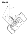
Fig. 10 , there is a problem that, depending on the direction in which thedustproof cap 103 is pulled out, thesecond fitting portion 105 contacts abolt 108 after thesecond fitting portion 105 has been detached from thesecond hole portion 102, thereby making detachment of thedustproof cap 103 from the compressor difficult. In particular, as shown inFig. 10 , there are cases where the vehicle air conditioner is mounted to a vehicle in a state where thebolt 108 is inclined and the direction in which thedustproof cap 103 is pulled out is restricted due to reasons of space. In a case where thehook portion 107 is gripped and pulled out in the direction of the arrow shown inFig. 10 , thedustproof cap 103 including thesecond fitting portion 105, as indicated by alternate long and two short dashed lines, catches on thebolt 108 and cannot be detached from theconnection block 100. Also with the sealing device disclosed inPatent Document 2, depending on the direction in which the sealing device is pulled out, the seal body detached from the suction port or the discharge port catches on the stud bolt in a manner similar to the case ofPatent Document 1, making reliable detachment of the sealing device from the compressor difficult. - An objective of the present invention is to provide a seal cap that can be detached reliably from a compressor, even when a cap portion that has been detached during removal of the seal cap contacts a stud bolt provided on the compressor.
- In accordance with one aspect of the present invention, a seal cap is provided that is adapted to be used in a compressor. The compressor includes a connection portion connecting a piping through which a fluid flows, a passage port opened at an end surface of the connection portion, and a stud bolt erected on the end surface of the connection portion. The seal cap is formed of an elastically deformable material and mounted to the connection portion. The seal cap includes a cap portion for closing the passage port, a grip portion, and a joining portion integrally joining the cap portion and the grip portion. The joining portion has a bolt insertion portion through which the stud bolt can be inserted. The grip portion is formed on a side of the bolt insertion portion that corresponds to the cap portion. The joining portion includes a cut that is formed on a side of the bolt insertion portion that corresponds to the cap portion and is in communication with the bolt insertion portion. The cut allows bending deformation of the cap portion by contacting of the cap portion with the stud bolt during pulling out of the seal cap from the connection portion.
- With the present invention, even if, in the process of pulling out the seal cap installed on the connection portion of the compressor, the cap portion that has become detached from the passage port contacts the stud bolt, the cap portion is bent with a fulcrum portion as a fulcrum by application of a force of pulling out the seal cap and becomes displaced with respect to the joining portion. By the displacement of the cap portion with respect to the joining portion, the catching of the cap portion on the stud bolt is avoided. By further application of the force of pulling out the seal cap, the seal cap is detached from the stud bolt. Consequently, the seal cap is detached reliably from the compressor.
- When a rectilinear distance between two points in the cut is defined as a distance from a position in communication with the bolt insertion portion to a position that is on side of the bolt insertion portion corresponding to the cap portion and is separated by the greatest distance from the bolt insertion portion, the rectilinear distance is preferably set to be greater than a length from the end surface of the connection portion to a distal end of the stud bolt.
- In this case, rupture from the cut is prevented because the cut is formed within the joining portion of the seal cap and does not reach an outer peripheral edge of the seal cap. Also, in the process of pulling out the seal cap, the stud bolt can be passed through the cut, thereby enabling the seal cap to be detached from the compressor more reliably.
- A configuration is preferably adapted in which the passage port forms a first passage port, the compressor includes a second passage port formed in the end surface of the connection portion, the stud bolt is erected between the first passage port and the second passage port, the cap portion forms a first cap portion, and a second cap portion for closing the second passage port is integrally joined to the first cap portion via the joining portion.
- In this case, at the connection portion of the compressor, the passage port and the second passage port are arranged with the stud bolt in between and the seal cap closes the passage port and the second passage port. In the process of pulling out the seal cap, the cap portion becomes detached first. After the catching of the cap portion on the stud bolt is avoided, the second cap becomes detached from the second passage port. The passage port and the second passage port can thus be closed by a single seal cap and the seal cap can be detached reliably from the compressor.
- A configuration is preferably adapted in which the cut forms a first cut, the joining portion includes a second cut on a side of the bolt insertion portion that corresponds to the second portion, and the second cut is in communication with the first cut.
- In this case, with the second cut, a position at which the force of pulling out the second cap portion acts after the catching of the cap portion on the stud bolt has been avoided in the process of pulling out the seal cap is made close to the second cap portion. Therefore, in comparison to a case where the second cut is not present, a smaller force is required to pull out the second cap portion and the pulling out of the seal cap is made easy.
- The cut is preferably formed from an outer peripheral edge of the joining portion to the bolt insertion portion.
- In this case, the cut reaches the outer peripheral edge of the seal cap. Thus, in the process of pulling out the seal cap, there is no need to pass the stud bolt through the cut after the catching of the cap portion on the stud bolt has been avoided. The cut can thus be made short in comparison to the cut formed at a position within the joining portion of the seal cap.
- A bolt protection portion, which covers an outer peripheral surface of the stud bolt, is preferably provided at a position of the joining portion that corresponds to the bolt insertion portion.
- In this case, the stud bolt is protected because the bolt protection portion covers the outer peripheral surface of the stud bolt in the state where the seal cap is installed on the connection portion.
- The bolt protection portion preferably has a cut extending from a distal end to a base portion of the bolt protection portion on a surface that corresponds to the cap portion.
- In this case, detachment of the bolt protection portion from the stud bolt is made easy in comparison to a case where a cut is not present in the bolt protection portion.
- The present invention provides a seal cap that can be detached reliably from a compressor even when a cap portion that has been detached during pulling out of the seal cap contacts a stud bolt provided on the compressor.
-
-
Fig. 1 is a side view of a compressor to which a seal cap according to a first embodiment of the present invention is applied; -
Fig. 2 is a front view of the compressor ofFig. 1 ; -
Fig. 3 is a perspective view of the seal cap according to the first embodiment of the present invention; -
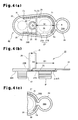
Fig. 4(a) is a plan view of the seal cap; -
Fig. 4(b) is a side view, with a part cut away, illustrating the seal cap; -
Fig. 4(c) is a partial plan view illustrating the seal cap, in which a circular hole formed by a grip portion and a cut are put in communication; -
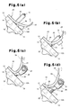
Figs. 5(a) to 5(d) are explanatory diagrams illustrating a process of pulling out the seal cap; -
Figs. 6(a) to 6(d) are plan views of seal caps according to first to fourth modifications of the first embodiment; -
Fig. 7(a) is a plan view of a seal cap according to a second embodiment; -
Fig. 7(b) is a side view, with a part cut away, illustrating the seal cap according to the second embodiment; -
Fig. 8(a) is a plan view of a seal cap according to a first modification of the second embodiment; -
Fig. 8(b) is a plan view of a seal cap according to a second modification of the second embodiment; -
Fig. 8(c) is a partially broken-away side view of the seal cap according to the second modification of the second embodiment; -
Fig. 9(a) is a plan view of a seal cap according to a third embodiment; -
Fig. 9(b) is a partially broken-away side view of the seal cap according to the third embodiment; and -
Fig. 10 is a partial side view, with a part cut away, illustrating a conventional art. - A seal cap according to a first embodiment of the present invention will now be described based on the drawings.
- A
compressor 10 shown inFigs. 1 and2 is a compressor to be installed in a vehicle. Ahousing 11 of thecompressor 10 is mainly formed by a cylinder block, a front housing member, and a rear housing member. Thehousing 11 is provided with aconnection portion 12 for connection with piping through which refrigerant flows as fluid. Anend surface 12A is formed on theconnection portion 12. Asuction port 13 as a passage port and adischarge port 14 as a second passage port are opened in theend surface 12A. Astud bolt 15 is erected on a portion of theend surface 12A between thesuction port 13 and thedischarge port 14. Thestud bolt 15 is a bolt for fixing the piping connected to theconnection portion 12 and is screwed into a threaded hole provided in theconnection portion 12. In the present embodiment, respective centers of thesuction port 13, thestud bolt 15, and thedischarge port 14 are arranged to pass a hypothetical straight line L at theconnection portion 12 of thecompressor 10 as shown inFig. 1 . As shown inFigs. 1 and2 , thecompressor 10 is fixed inside an engine compartment of the vehicle so that theconnection portion 12 of thecompressor 10 is set at a position inclined by approximately 45 degrees with a rotation axis P as a center. - A
seal cap 20 shown inFig. 3 ,Fig. 4(a), and 4(b) is installed on theconnection portion 12 to close thesuction port 13 and thedischarge port 14. Theseal cap 20 is formed, for example, of a plastic material, such as polyurethane, etc., or a rubber-based material that can be deformed elastically by pressurization by a manual force. Theseal cap 20 includes afirst cap portion 21 for thesuction port 13, asecond cap portion 22 for thedischarge port 14, agrip portion 24, and abolt protection portion 25. Further, theseal cap 20 has a joiningportion 26, which integrally joins thefirst cap portion 21, thesecond cap portion 22, thegrip portion 24, and thebolt protection portion 25. Also, the joiningportion 26 has abolt insertion portion 23. - The
first cap portion 21 is formed to have a columnar shape, and a plurality of annular ribs 21Aare formed on an outer peripheral surface of thefirst cap portion 21. A recess (not shown), which is formed to enter inside from a distal side of thefirst cap portion 21, is provided. The outer diameter dimension of thefirst cap portion 21 is set in accordance with an inner diameter of thesuction port 13 so that it closes thesuction port 13 by being press-fitted. Thesecond cap portion 22 is formed to have a columnar shape. Thesecond cap portion 22 includes a plurality ofannular ribs 22A at an outer peripheral surface and includes, in its interior, a recess (not shown) of the same form as that of thefirst cap portion 21. The outer diameter dimension of thesecond cap portion 22 is set in accordance with an inner diameter of thedischarge port 14 so that it closes thedischarge port 14 by being press-fitted. - The
bolt insertion portion 23 is a portion through which thestud bolt 15 can be inserted and is positioned between thefirst cap portion 21 and thesecond cap portion 22. In the present embodiment, thebolt protection portion 25 is formed to have a cylindrical shape at a position of the joiningportion 26 corresponding to thebolt insertion portion 23. The cylindrical inner side portion of thebolt protection portion 25 corresponds to thebolt insertion portion 23. In a state where theseal cap 20 is installed on theconnection portion 12, thestud bolt 15 is inserted through thebolt insertion portion 23 and thebolt protection portion 25 covers an outer peripheral surface of thestud bolt 15. - The
grip portion 24 is for facilitating the pulling out of theseal cap 20 installed on theconnection portion 12. In the present embodiment, thegrip portion 24 is formed at a position at one end of theseal cap 20 that is adjacent to thefirst cap portion 21. That is, thegrip portion 24 is formed at a position opposite thebolt insertion portion 23 with thefirst cap portion 21 as a center. Acircular hole 24A is formed in thegrip portion 24 and thegrip portion 24 has a ring-like shape. Thefirst cap portion 21 is positioned between thegrip portion 24 and thebolt insertion portion 23. Thegrip portion 24 may be changed in position to any position as long as it is positioned on the side of thebolt insertion portion 23 that corresponds to thefirst cap portion 21. Also, thegrip portion 24 is not particularly restricted in shape and may be changed to any shape as long as it is a shape that is capable of being gripped. When pulling out theseal cap 20 installed on theconnection portion 12, theseal cap 20 is pulled out easily by latching a finger on thegrip portion 24 and pulling in a pulling-out direction. - The joining
portion 26 integrally joins thefirst cap portion 21, thesecond cap portion 22, and thegrip portion 24. As shown inFig. 4(b) , the joiningportion 26 includes a contactingsurface 26A, which contacts theend surface 12A of theconnection portion 12. Also, athick rib 26B is formed at an outer peripheral edge of the joiningportion 26. As shown inFig. 3 and4(a) , in the present embodiment, within a range that is within the joiningportion 26 and surrounded by therib 26B, afirst cut 27 is formed in a region close to thefirst cap portion 21 from thebolt insertion portion 23, and asecond cut 29 is formed on a side of thebolt insertion portion 23 that corresponds to thesecond cap portion 22. That is, thefirst cut 27 is located between thebolt insertion portion 23 and thegrip portion 24. - As shown in
Figs. 3 and4(a) , thefirst cut 27 includes atransverse portion 27A, which extends along a side of thefirst cap portion 21 that corresponds to thebolt insertion portion 23 in a traversing manner and is in communication with thebolt insertion portion 23, and an outerperipheral portion 27B formed to extend from thetransverse portion 27A toward thegrip portion 24 along therib 26B. Here, "traversing manner" does not refer to extending completely across in a direction orthogonal to a longitudinal direction of theseal cap 20, in other words, a direction orthogonal to a direction of approaching thesecond cap portion 22 from thegrip portion 24 but refers to extending partially across in that direction. Thetransverse portion 27A of thefirst cut 27 is formed rectilinearly in the traversing direction between thefirst cap portion 21 and thebolt protection portion 25 and is in communication with thebolt insertion portion 23. Thefirst cut 27 includes a plurality of ends T1 to T4. The end T3 of the outerperipheral portion 27B of thefirst cut 27 is in communication with the end T1 of thetransverse portion 27A, and the outerperipheral portion 27B extends along therib 26B and between thegrip portion 24 and thefirst cap portion 21. The end T4 of the outerperipheral portion 27B is positioned at the same side of the joiningportion 26 as the end T2 of thetransverse portion 27A. - A point R in the outer
peripheral portion 27B that is separated by the greatest distance from the center of thetransverse portion 27A is present between thefirst cap portion 21 and thegrip portion 24. Here, the center of thetransverse portion 27A is the position at which first cut 27 is in communication with thebolt insertion portion 23. Also, in thefirst cut 27, the furthest point R is a position on a side of thebolt insertion portion 23 that corresponds to thefirst cap portion 21 and is separated from thebolt insertion portion 23 by the greatest distance. As shown inFig. 4(b) , a rectilinear distance D1 between the two points of the furthest point R of the outerperipheral portion 27B and the center of thetransverse portion 27A is set to be greater than a length D2 from theend surface 12A to a distal end of thestud bolt 15. Since the rectilinear distance D1 is set to be greater than the length D2 from theend surface 12A to the distal end of thestud bolt 15, thestud bolt 15 is enabled to pass through thefirst cut 27 during the pulling out of theseal cap 20. - Since the
first cut 27 is formed in the joiningportion 26, afulcrum portion 28 is formed at a portion of the joiningportion 26 between the end T2 of the outerperipheral portion 27B and the end T4 of thetransverse portion 27A. InFigs. 3 and4(a) , thefulcrum portion 28 is indicated by a broken line in which a long dash alternates with a pair of short dashes for the illustrative purposes. Thefulcrum portion 28 is a portion that functions as a fulcrum at which thefirst cap portion 21 can be displaced with respect to the joiningportion 26. Thefulcrum portion 28 is formed at a position of the joiningportion 26 that is separated from a portion betweenfirst cap portion 21 and thebolt insertion portion 23. Since thefulcrum portion 28 is formed in the joiningportion 26, even when thefirst cap portion 21 contacts thestud bolt 15 during the pulling out of theseal cap 20, thefirst cap portion 21 bends with thefulcrum portion 28 as the fulcrum, thereby avoiding catching of thefirst cap portion 21 on thestud bolt 15. As shown inFig. 4(c) , thefirst cut 27 may be in communication with thecircular hole 24A formed by thegrip portion 24. In this case, thestud bolt 15 is made to pass through thefirst cut 27 even more easily. - The
second cut 29 will now be described. - The
second cut 29 is formed by cutting rectilinearly along therib 26B from both ends T1 and T2 of thetransverse portion 27A of thefirst cut 27 toward thesecond cap portion 22. In the present embodiment, ends T5 and T6 of thesecond cut 29 near thesecond cap portion 22 are made closer to thesecond cap portion 22 than thebolt insertion portion 23. The ends T5 and T6 of thesecond cut 29 near thesecond cap portion 22 are made closer to thesecond cap portion 22 than the area between thebolt insertion portion 23 and thesecond cap portion 22. Asecond fulcrum portion 30 is thereby formed near thesecond cap portion 22. - Since the
second fulcrum portion 30 is formed closer to thesecond cap portion 22 than thebolt insertion portion 23, a force pulling out thesecond cap portion 22 during the pulling out of theseal cap 20 is made to act more readily on thesecond cap portion 22. Since the position of thesecond fulcrum portion 30 is made closer to thesecond cap portion 22 than thebolt insertion portion 23, the force of pulling out thesecond cap portion 22 is made to act more readily on thesecond cap portion 22. In contrast, since the position of thesecond fulcrum portion 30 is made closer to thebolt insertion portion 23 than thesecond cap portion 22, the acting of the force of pulling out of thesecond cap portion 22 on thesecond cap portion 22 is made more difficult. - Although, in the present embodiment, the width of each of the
first cut 27 and thesecond cut 29 is set to approximately 1 mm, the widths of the first andsecond cuts second cuts portion 26 or may be cuts that are formed in a perforated manner. In the case of a recessed grooves or perforated cuts, it suffices that the cuts become cut completely from the top surface to the rear surface of the joiningportion 26 by the pulling-out force during the pulling out of theseal cap 20. - A process of pulling out the
seal cap 20 of the present embodiment will now be described. - The
compressor 10 is mounted inside the engine compartment of the vehicle and thestud bolt 15 provided on theconnection portion 12 is in a state of being inclined by approximately 45 degrees with respect to the vertical direction. Theseal cap 20 is installed on theconnection portion 12 of thecompressor 10 with thefirst cap portion 21 of theseal cap 20 closing thesuction port 13 and thesecond cap portion 22 closing thedischarge port 14. A worker performing the process of pulling out theseal cap 20 first latches a finger on thegrip portion 24 and moves the latched finger upward so that it approaches thestud bolt 15. The joiningportion 26 thereby becomes arched and a vicinity of thegrip portion 24 of theseal cap 20 begins to separate from theend surface 12A of theconnection portion 12. By pulling up thegrip portion 24 further in a direction of an arrow shown inFig. 5(a) , thefirst cap portion 21 becomes detached from thesuction port 13. In each ofFigs. 5(a) to 5(d) , the direction of the arrow is upward, and the pulling out of theseal cap 20 is performed in the order ofFigs. 5(a), 5(b), 5(c), and 5(d) . - By pulling up the
grip portion 24 further, thefirst cap portion 21 is put in contact with thestud bolt 15 as shown inFig. 5(b) . By continuing to pull up thegrip portion 24, thefirst cap portion 21 becomes bent with thefulcrum portion 28 as the fulcrum and theseal cap 20 is separated further from theend surface 12A of theconnection portion 12 as shown inFig. 5(c) . Thefirst cap portion 21 passes by a side of thestud bolt 15 in a bent state and moves toward thesecond cap portion 22. In this process, thestud bolt 15 passes through thefirst cut 27 in the state of being covered by thebolt protection portion 25. The displacedfirst cap portion 21 is positioned at a side of thefulcrum portion 28 and thestud bolt 15 and thefirst cap portion 21 are contacted in the pulling-out direction. Catching of thefirst cap portion 21 on thestud bolt 15 is thereby avoided. - When the
grip portion 24 is pulled further upward from this state, thesecond cap portion 22 begins to become detached from thedischarge port 14 and thebolt protection portion 25 begins to be removed from thestud bolt 15 as shown inFig. 5(d) . At this point, the force of pulling out can be made to act on thesecond cap portion 22 readily because thesecond fulcrum portion 30 is set closer to thesecond cap portion 22 than thebolt insertion portion 23. In comparison to a case where the second fulcrum portion is further away, thesecond cap portion 22 can be detached with a lower force. After thesecond cap portion 22 has become detached from thedischarge port 14 or at the same time as the detachment ofsecond cap portion 22, thebolt protection portion 25 becomes removed from thestud bolt 15 and the pulling out of theseal cap 20 is completed. - The above described embodiment achieves the following advantages.
- (1) Even if, in the process of pulling out the
seal cap 20 installed on theconnection portion 12 of thecompressor 10, thefirst cap portion 21, which has become detached from thesuction port 13, contacts thestud bolt 15, thefirst cap portion 21 is bent with thefulcrum portion 28 of the joiningportion 26 as the fulcrum by the application of the force of pulling out theseal cap 20. By the bending of thefirst cap portion 21, catching of thefirst cap portion 21 on thestud bolt 15 in the pulling-out direction is avoided and thefirst cap portion 21 does not hinder the pulling out of theseal cap 20. When the force of pulling out theseal cap 20 is applied further, theseal cap 20 becomes detached from thestud bolt 15. Consequently, theseal cap 20 is detached from thecompressor 10 reliably. - (2) The
first cut 27 is formed at a position within the joiningportion 26 of theseal cap 20. Thus, in the process of pulling out theseal cap 20, thestud bolt 15 can be passed through thefirst cut 27, thereby enabling the detachment of theseal cap 20 from thecompressor 10 to be performed more reliably. Also, thefirst cut 27 does not reach the outer peripheral edge of theseal cap 20. Thus, after thefirst cap portion 21 has been pulled out in the process of pulling out theseal cap 20, thebolt insertion portion 23 and thesecond cap portion 22 can be detached by reference to the two points of the ends T5 and T6. That is, when pulling out thebolt insertion portion 23 and thesecond cap portion 22, the force of pulling out is dispersed among the ends T5 and T6. For example, if the end T2 of thefirst cut 27 reaches the outer peripheral edge, the force of pulling out will act on the single point of the end T5 when thebolt insertion portion 23 and thesecond cap portion 22 are pulled out. Thus, in comparison to the case where thefirst cut 27 reaches the outer peripheral edge of theseal cap 20, the present embodiment has a structure with which theseal cap 20 has a high strength against the pulling-out force. - (3) In the
connection portion 12 of thecompressor 10, thesuction port 13 and thedischarge port 14 are arranged such that thestud bolt 15 is positioned between twoports suction port 13 and thedischarge port 14 are closed by thesingle seal cap 20, and thestud bolt 15 is inserted through thebolt insertion portion 23 of theseal cap 20. In the process of pulling out theseal cap 20, thefirst cap portion 21 becomes detached first. Then, after the catching of thefirst cap portion 21 on thestud bolt 15 has been avoided, thesecond cap portion 22 is detached from thedischarge port 14. Thesuction port 13 and thedischarge port 14 can thus be closed by thesingle seal cap 20, and theseal cap 20 can be detached reliably from thecompressor 10. - (4) The
seal cap 20 is provided with thesecond cut 29. The position at which the force of pulling out thesecond cap portion 22 acts after the catching of thefirst cap portion 21 on thestud bolt 15 has been avoided in the process of pulling out theseal cap 20 is thereby made close to thesecond cap portion 22. Therefore, in comparison to a case where thesecond cut 29 is not present, the force of pulling out thesecond cap portion 22 is lessened and the pulling out is made easier. - (5) In a state where the
seal cap 20 is installed on theconnection portion 12, thebolt protection portion 25 covers thestud bolt 15. Thestud bolt 15 is thus protected in the state where theseal cap 20 is installed on theconnection portion 12. - (6) The
seal cap 20 has a high strength against the force of pulling out because therib 26B is formed on theseal cap 20. - First to fourth modifications of the first embodiment will now be described.
- A first modification shown in
Fig. 6(a) is an example of theseal cap 20 in which the position of thefirst cut 27 differs from that of the first embodiment. Outerperipheral portions 27B are respectively formed to extend toward thegrip portion 24 from the ends T1 and T2 of thetransverse portion 27A. The ends T3 at one side of the outerperipheral portions 27B are in communication with the respective ends T1 and T2 of thetransverse portion 27A, and the other ends T4 of the outerperipheral portions 27B are the furthest points R. Therefore, with theseal cap 20 of the first modification, thefulcrum portion 28 in the joiningportion 26 is formed between thegrip portion 24 and thefirst cap portion 21. A rectilinear distance between each of the ends T4 of the outerperipheral portions 27B near thegrip portion 24 and thetransverse portion 27A is set to be greater than the length from theend surface 12A to the distal end of thestud bolt 15. With the first modification, in the process of pulling out theseal cap 20, thefirst cap portion 21 bends with thefulcrum portion 28 as the fulcrum at the distal side of thestud bolt 15 and thefirst cap portion 21 passes along the distal side of thestud bolt 15 while staying in the bent state and moves toward thesecond cap portion 22. By the bending of thefirst cap portion 21, the catching of thefirst cap portion 21 on thestud bolt 15 in the pulling-out direction is avoided. - A second modification shown in
Fig. 6(b) is an example of theseal cap 20 in which thesecond cut 29 is formed to extend only from one end T1 of thetransverse portion 27A and a cut is not formed at the other end T2 of thetransverse portion 27A. With the second modification, although thesecond cut 29 is only formed to extend from the one end T1 of thetransverse portion 27A, thesecond fulcrum portion 30 can be formed by the end T5. The force of pulling out can thus be made to act readily on thesecond cap portion 22 in the process of pulling out theseal cap 20. - A third modification shown in
Fig. 6(c) is an example of theseal cap 20 in which only thefirst cut 27 is formed and thesecond cut 29 is omitted. Although the third modification has an arrangement where thesecond cap portion 22 is difficult to detach in comparison to the first embodiment and the first and second modifications, thesecond cap portion 22 can be detached from thedischarge port 14 by making the pulling-out force greater than in the case of the second modification. The catching of the suction-side cap portion 21 on thestud bolt 15 in the pulling-out direction is avoided due to the bending of thefirst cap portion 21 in the present case as well. - A fourth modification shown in
Fig. 6(d) is an example of theseal cap 20 that does not include thebolt protection portion 25. With the fourth modification, the joiningportion 26 has thebolt insertion portion 23, and thefirst cap portion 21 and thegrip portion 24 are joined integrally by the joiningportion 26. With the fourth modification, thetransverse portion 27A of thefirst cut 27 is in communication with thebolt insertion portion 23. With theseal cap 20 of the fourth modification, even when theseal cap 20 is installed on theconnection portion 12, thestud bolt 15 is exposed and not protected because thebolt protection portion 25 is not provided. In the process of pulling out theseal cap 20, there is no need to make thebolt protection portion 25 become detached from thestud bolt 15. Thus, the detachment of theseal cap 20 is made correspondingly easier. - A seal cap according to a second embodiment of the present invention will now be described.
- The seal cap according to the second embodiment is an example in which a first cut reaches an outer peripheral edge of the joining portion. In regard to elements in common with the first embodiment, the description of the first embodiment will be invoked and the symbols will be used in common.
- A
first cut 41 is formed in the joiningportion 26 of aseal cap 40 shown inFig. 7 , and thefirst cut 41 extends from the outer peripheral edge of the joiningportion 26 to thebolt insertion portion 23. Thefirst cut 41 is thus a cut traversing from the outer peripheral edge of the joiningportion 26 to thebolt insertion portion 23. Also, thefirst cut 41 is positioned on a side of thebolt insertion portion 23 that corresponds to thefirst cap portion 21. In the joiningportion 26,fulcrum portions first cut 41 across thebolt insertion portion 23. Thefulcrum portion 42 is a fulcrum for displacement of thefirst cap portion 21 toward thebolt protection portion 25 in the process of pulling out theseal cap 40. That is, in the process of gripping thegrip portion 24 and pulling out theseal cap 40 toward thestud bolt 15, theseal cap 40 bends with thefulcrum portion 42 as the fulcrum and thefirst cap portion 21 becomes detached. Thefulcrum portion 43 is a fulcrum for making thefirst cap portion 21 become displaced in the state of contacting thestud bolt 15 to avoid catching on thestud bolt 15 in the process of pulling out theseal cap 40. Thefulcrum portion 43 is the fulcrum necessary for making thefirst cap portion 21 become displaced to avoid catching on thestud bolt 15 in the process of pulling out theseal cap 40. In theseal cap 40 according to the present embodiment, the second cut is not present. - With the
seal cap 40, in the process of pulling out theseal cap 40, thefirst cap portion 21 bends with thefulcrum portion 42 as the fulcrum and becomes displaced toward thestud bolt 15 until it contacts thestud bolt 15. Then, when thefirst cap portion 21 contacts thestud bolt 15, thefirst cap portion 21 becomes displaced with thefulcrum portion 43 as the fulcrum. By pulling out further, thefirst cap portion 21 bends with thefulcrum portion 43 as the fulcrum with thefirst cap portion 21 remaining in contact with thestud bolt 15 and passes a portion of thestud bolt 15 near thefulcrum portion 43. By continuing to pull out, detachment of thesecond cap portion 22 and thebolt protection portion 25 is performed. - With the present embodiment, substantially the same advantages as items (1), (3), (5), and (6) of the first embodiment are achieved. Further, with the present embodiment, the
first cut 41 reaches the outer peripheral edge of theseal cap 40. Thus, in the process of pulling out theseal cap 40, there is no need to make thestud bolt 15 pass through thefirst cut 41 after the catching of thefirst cap portion 21 on thestud bolt 15 has been avoided. Therefore, in comparison to thefirst cut 27 formed at a position within the joiningportion 26 in theseal cap 20 of the first embodiment, the length of thefirst cut 41 is smaller in the second embodiment. With the present embodiment, the structure of theseal cap 20 is simplified in comparison to the first embodiment. Also, thefirst cut 41 is provided in a region close to thefirst cap portion 21 from thebolt insertion portion 23. Further, the cut extends obliquely from thebolt insertion portion 23 to approach thefirst cap portion 21 and the joiningportion 26 is thus made readily bendable with thefulcrum portion 42 as the fulcrum in the pulling out process. - First and second modifications of the second embodiment will now be described.
- Afirst modification shown in
Fig. 8(a) is an example of theseal cap 40 in which asecond cut 44 is formed in addition to thefirst cut 41. The first cut 41 of the first modification is formed to pass a side of thefirst cap portion 21 that corresponds to thebolt insertion portion 23 in a traversing manner and is in communication with thebolt insertion portion 23. With the first modification, thefulcrum portions first cut 41. - On the other hand, the
second cut 44 is formed to extend from an end of thefirst cap portion 21 in the joiningportion 26 toward thesecond cap portion 22 along therib 26B and is further formed to pass between thebolt protection portion 25 and thesecond cap portion 22. With the first modification, asecond fulcrum portion 45 is formed in the joiningportion 26 by the forming of thesecond cut 44. Since thesecond fulcrum portion 45 is formed close to thesecond cap portion 22, the force of pulling out thesecond cap portion 22 is made to act readily on thesecond cap portion 22 during the pulling out of theseal cap 40. Thus, in comparison to theseal cap 40 of the second embodiment, the detachment ofsecond cap portion 22 occurs before the detachment of thebolt protection portion 25 from thestud bolt 15 and the detachment of thesecond cap portion 22 is thus made easy. - A second modification shown in
Fig. 8(b) and 8(c) is an example of theseal cap 40 in which acut 46 is formed in thebolt protection portion 25 in theseal cap 40 according to the second embodiment. Thecut 46, which extends from abase portion 25A to thedistal end 25B of thebolt protection portion 25 provided in theseal cap 40, is formed on a peripheral surface of thebolt protection portion 25 that corresponds to thefirst cap portion 21. Since thecut 46 is formed in thebolt protection portion 25, thecut 46 of thebolt protection portion 25 is opened by pulling out further after thefirst cap portion 21 has become detached in the process of pulling out theseal cap 40. Thebolt protection portion 25 thereby becomes detached from thestud bolt 15. Further, thesecond cap portion 22 becomes detached from thedischarge port 14. With the second modification, the detachment of thebolt protection portion 25 from thestud bolt 15 is made easier in comparison to a case where thebolt protection portion 25 does not have thecut 46. - A seal cap according to a third embodiment of the present invention will now be described.
- The third embodiment is an example of a seal cap that includes a cap portion that closes only the suction hole. A
seal cap 50 shown inFigs. 9(a) and 9(b) includes acap portion 51, agrip portion 54, and a joiningportion 56 that is integrally formed with thecap portion 51 and thegrip portion 54. The joiningportion 56 includes abolt insertion portion 53 and includes abolt protection portion 55 at a position corresponding to thebolt insertion portion 53. - The
cap portion 51 closes thesuction port 13 and has a columnar shape. Thegrip portion 54 is for facilitating the pulling out of theseal cap 50 during the pulling out of theseal cap 50. Thegrip portion 54 has acircular hole 54A and has substantially the same arrangement as thegrip portion 24 of the first embodiment. Thebolt insertion portion 53 is the portion through which thestud bolt 15 is inserted, and in the present embodiment, thebolt protection portion 55 is formed at the position of the joiningportion 56 corresponding to thebolt insertion portion 53. A through hole at a position within thebolt protection portion 55 corresponds to thebolt insertion portion 53. The joiningportion 56 includes anend surface 56A that contacts theend surface 12A of theconnection portion 12 and arib 56B formed along an outer peripheral edge. In the present embodiment, acut 57, formed on a side of thebolt insertion portion 53 that corresponds to thecap portion 51, is formed in a range within and surrounded by therib 56B of the joiningportion 56. - As shown in
Fig. 9(a) , thecut 57 includes atransverse portion 57A, which is formed to pass thebolt insertion portion 53 of thecap portion 51 in a traversing manner and in communication with thebolt insertion portion 53, and an outerperipheral portion 57B, which is formed to extend from thetransverse portion 57A toward thegrip portion 54 along therib 56B. Thetransverse portion 57A of thecut 57 is formed to extend rectilinearly between thecap portion 51 and thebolt protection portion 55 and is in communication with thebolt insertion portion 53. An end T3 of the outerperipheral portion 57B of thecut 57 is in communication with an end T1 of thetransverse portion 57A. The outerperipheral portion 57B extends along therib 56B and passes between thegrip portion 54 and thecap portion 51. An end T4 of the outerperipheral portion 57B is positioned at the same side as an end T2 of thetransverse portion 57A. - A point R in the outer
peripheral portion 57B that is separated by the greatest distance from the center of thetransverse portion 57A is present between thecap portion 51 and thegrip portion 54. A rectilinear distance between the furthest point R of the outerperipheral portion 57B and the center of thetransverse portion 57A is set to be greater than the length from theend surface 12A to the distal end of thestud bolt 15. Since thecut 57 is formed in the joiningportion 56, afulcrum portion 58 is formed at a portion of the joiningportion 56 between the end T4 of the outerperipheral portion 57B and the end T2 of thetransverse portion 57A. - With the present embodiment, even if, in the process of pulling out the
seal cap 50 installed on theconnection portion 12 of thecompressor 10, thecap portion 51, which has become detached from thesuction port 13, contacts thestud bolt 15, thecap portion 51 is bent with thefulcrum portion 58 of the joiningportion 56 as the fulcrum and becomes displaced with respect to the joiningportion 56. By the displacement of thecap portion 51 with respect to the joiningportion 56, catching of thecap portion 51 on thestud bolt 15 is avoided and thecap portion 51 does not hinder the pulling out of theseal cap 50. Thecut 57 may be put in communication with thecircular hole 54A of thegrip portion 54. In this case, thestud bolt 15 passes through thecut 57 even more easily. A seal cap having the same arrangement as theseal cap 50 and adapted for thedischarge port 14 may also be used for thedischarge port 14. - Each of the seal caps according to the embodiments described above demonstrates an embodiment of the present invention, and the present invention is not restricted to the embodiments described above. Various changes may be made within the scope of the gist of the invention as described below.
- Although with each of the embodiments described above, the vehicle-installed compressor is described as an example of a compressor on which the seal cap is installed, the type of compressor is not restricted in particular. For example, the compressor may be of a swash plate type, scroll type, or vane type and is also not restricted to a vehicle-installed compressor.
- Although with each of the embodiments described above, an example is described where the seal cap is installed on the connection portion formed on the housing of the compressor, the connection portion is not restricted to being formed on the housing. For example, the connection portion may be formed on another member provided on the housing.
- Although in each of the embodiments described above, the respective centers of the suction port, the stud bolt, and the discharge port are arranged to pass through the hypothetical straight line in the connection portion of the compressor, the respective centers the suction port, the stud bolt, and the discharge port may instead be shifted in position with respect to each other. In this case, in the seal cap, the first cap portion, the bolt insertion portion, and the second cap portion are changed to shapes that are shifted in position with respect each other in accordance with the positions of the suction port, the stud bolt, and the discharge port.
- Although with each of the embodiments described above, the compressor is fixed inside the engine compartment so that the suction port is set at a lower position than the discharge port, the compressor may be one that is fixed such that the discharge port is set at a lower position than the suction port. With the seal cap in this case, for example, the position of the second cap portion for the discharge port and the position of the first cap portion for the suction port are interchanged and the grip portion is provided near the cap portion for the discharge port.
- Although with each of the embodiments described above, the grip portion is formed to have a ring-like shape, the grip portion suffices to be of a shape that can be gripped readily by the worker in the process of pulling out the seal caption and the shape is not restricted in particular. Also, the grip portion suffices to be provided to be present on a side of the bolt insertion portion that corresponds to the cap portion.
- Although with each of the embodiments described above, the rib is provided to extend along the outer peripheral edge of the seal cap, the providing of the rib is not essential. For example, the rib may be omitted.
- With each of the embodiments described above, an example is described where the compressor is mounted to the engine compartment in the state where the stud bolt provided on the connection portion is inclined by approximately 45 degrees with respect to the vertical direction. However, the direction of the stud bolt is not restricted in particular and may be changed as suited. For example, the stud bolt may be arranged in the vertical direction or may be arranged to be inclined at an angle other than 45 degrees.
- In each of the embodiments described above, the rectilinear distance between two points in the cut from the position in communication with the bolt insertion portion to the position R, which is separated by the greatest distance from the insertion portion is set to be greater than the length from the end surface to the distal end of the stud bolt. However, depending on the material of the seal cap, the distance may be changed. In a case where the material of the seal cap has a sufficient elongation allowance, for example, in a case of a rubber-based material, the rectilinear distance between the two points may be set to be smaller than the length from the end surface to the distal end of the stud bolt.
Claims (7)
- A seal cap adapted to be used in a compressor that includes a connection portion connecting a piping through which a fluid flows, a passage port opened at an end surface of the connection portion, and a stud bolt erected on the end surface of the connection portion, wherein the seal cap is formed of an elastically deformable material and mounted to the connection portion, the seal cap comprising:a cap portion for closing the passage port;a grip portion; anda joining portion integrally joining the cap portion and the grip portion; andwherein the joining portion has a bolt insertion portion through which the stud bolt can be inserted,the seal cap being characterized in thatthe grip portion is formed on a side of the bolt insertion portion that corresponds to the cap portion,the joining portion includes a cut that is formed on a side of the bolt insertion portion that corresponds to the cap portion and is in communication with the bolt insertion portion, andthe cut allows bending deformation of the cap portion by contacting of the cap portion with the stud bolt during pulling out of the seal cap from the connection portion.
- The seal cap according to claim 1, characterized in that, when a rectilinear distance between two points in the cut is defined as a distance from a position in communication with the bolt insertion portion to a position that is on side of the bolt insertion portion corresponding to the cap portion and is separated by the greatest distance from the bolt insertion portion, the rectilinear distance is set to be greater than a length from the end surface of the connection portion to a distal end of the stud bolt.
- The seal cap according to claim 1 or 2, characterized in that the passage port forms a first passage port,
the compressor includes a second passage port formed in the end surface of the connection portion,
the stud bolt is erected between the first passage port and the second passage port, the cap portion forms a first cap portion, and
a second cap portion for closing the second passage port is integrally joined to the first cap portion via the joining portion. - The seal cap according to claim 3, characterized in that
the cut forms a first cut,
the joining portion includes a second cut on a side of the bolt insertion portion that corresponds to the second portion, and
the second cut is in communication with the first cut. - The seal cap according to claim 1, characterized in that the cut is formed from an outer peripheral edge of the joining portion to the bolt insertion portion.
- The seal cap according to claim 1 or 2, characterized in that a bolt protection portion, which covers an outer peripheral surface of the stud bolt, is provided at a position of the joining portion that corresponds to the bolt insertion portion.
- The seal cap according to claim 6, characterized in that the bolt protection portion has a cut extending from a distal end to a base portion of the bolt protection portion on a surface that corresponds to the cap portion.
Applications Claiming Priority (2)
| Application Number | Priority Date | Filing Date | Title |
|---|---|---|---|
| JP2010212007A JP5429122B2 (en) | 2010-09-22 | 2010-09-22 | Seal cap |
| PCT/JP2011/071393 WO2012039401A1 (en) | 2010-09-22 | 2011-09-20 | Seal cap |
Publications (2)
| Publication Number | Publication Date |
|---|---|
| EP2620647A1 true EP2620647A1 (en) | 2013-07-31 |
| EP2620647A4 EP2620647A4 (en) | 2016-05-11 |
Family
ID=45873886
Family Applications (1)
| Application Number | Title | Priority Date | Filing Date |
|---|---|---|---|
| EP11826846.5A Withdrawn EP2620647A4 (en) | 2010-09-22 | 2011-09-20 | Seal cap |
Country Status (5)
| Country | Link |
|---|---|
| US (1) | US9133934B2 (en) |
| EP (1) | EP2620647A4 (en) |
| JP (1) | JP5429122B2 (en) |
| CN (1) | CN103119298B (en) |
| WO (1) | WO2012039401A1 (en) |
Families Citing this family (7)
| Publication number | Priority date | Publication date | Assignee | Title |
|---|---|---|---|---|
| CN104006201A (en) * | 2013-11-28 | 2014-08-27 | 广西柳工奥兰空调有限公司 | Vehicle air condition dust cap |
| DE102015112447A1 (en) * | 2015-07-30 | 2017-02-02 | Robert Bosch Automotive Steering Gmbh | Pressure medium conveying device and sealing device for sealing a pressure medium conveying device |
| US10898294B2 (en) * | 2015-12-22 | 2021-01-26 | Stoma Ventures, LLC | Tail cap for dental equipment |
| JP6809405B2 (en) | 2017-07-31 | 2021-01-06 | 株式会社豊田自動織機 | Seal cap |
| JP6947628B2 (en) * | 2017-12-27 | 2021-10-13 | トヨタ車体株式会社 | Hole plug mounting structure |
| US11060653B2 (en) * | 2018-08-09 | 2021-07-13 | Hanon Systems | Gap filling shipping cap for leveraged refrigerant fitting |
| US20230322470A1 (en) * | 2022-04-08 | 2023-10-12 | Richard Lee Gonzalez | Double Wall Insulated Vessel with Top and Side Openings |
Family Cites Families (12)
| Publication number | Priority date | Publication date | Assignee | Title |
|---|---|---|---|---|
| GB9310609D0 (en) * | 1993-05-22 | 1993-07-07 | Moss Plastic Parts Ltd | An article including at least one projection |
| JPH09210284A (en) * | 1996-01-30 | 1997-08-12 | Zexel Corp | Piping connector cap |
| US5988223A (en) * | 1996-11-28 | 1999-11-23 | Kabushiki Kaisha Toyoda Jidoshokki Seisakusho | Sealing plug device for a refrigerant compressor |
| JP3648940B2 (en) | 1997-09-04 | 2005-05-18 | 株式会社デンソー | Channel blocker |
| JPH11210629A (en) * | 1998-01-21 | 1999-08-03 | Toyota Autom Loom Works Ltd | Plug sealing device of compressor |
| JP2973000B1 (en) | 1998-06-22 | 1999-11-08 | 株式会社ゼクセル | cap |
| US6290092B1 (en) * | 1999-03-18 | 2001-09-18 | Pratt & Whitney Canada Corp. | Disposable protective closure |
| JP3923327B2 (en) * | 2002-02-04 | 2007-05-30 | サンデン株式会社 | Port cover |
| JP4441468B2 (en) | 2005-09-20 | 2010-03-31 | 株式会社ケーヒン | Dust-proof cap used in vehicle air conditioners |
| JP3124207U (en) * | 2006-05-30 | 2006-08-10 | 株式会社ヴァレオサーマルシステムズ | Sealing device |
| KR20080010678A (en) * | 2006-07-27 | 2008-01-31 | 한라공조주식회사 | Compressor inlet port protection structure |
| JP4981876B2 (en) * | 2009-11-18 | 2012-07-25 | 株式会社ケーヒン | Dust-proof cap used in vehicle air conditioners |
-
2010
- 2010-09-22 JP JP2010212007A patent/JP5429122B2/en not_active Expired - Fee Related
-
2011
- 2011-09-20 EP EP11826846.5A patent/EP2620647A4/en not_active Withdrawn
- 2011-09-20 CN CN201180044858.2A patent/CN103119298B/en not_active Expired - Fee Related
- 2011-09-20 WO PCT/JP2011/071393 patent/WO2012039401A1/en not_active Ceased
- 2011-09-20 US US13/823,554 patent/US9133934B2/en not_active Expired - Fee Related
Also Published As
| Publication number | Publication date |
|---|---|
| JP5429122B2 (en) | 2014-02-26 |
| CN103119298B (en) | 2015-11-25 |
| EP2620647A4 (en) | 2016-05-11 |
| CN103119298A (en) | 2013-05-22 |
| WO2012039401A1 (en) | 2012-03-29 |
| JP2012067648A (en) | 2012-04-05 |
| US9133934B2 (en) | 2015-09-15 |
| US20130175768A1 (en) | 2013-07-11 |
Similar Documents
| Publication | Publication Date | Title |
|---|---|---|
| US9133934B2 (en) | Seal cap | |
| US7722086B2 (en) | Falling-off prevention structure for connector | |
| EP2555363A1 (en) | Grommet for wire harness | |
| JP5098828B2 (en) | Grommet | |
| US10000110B2 (en) | Air conditioning system for motor vehicles | |
| US8895860B2 (en) | Grommet | |
| WO2015098129A1 (en) | Drain hose | |
| EP3267009A1 (en) | Waste gate valve and turbocharger | |
| US10618382B2 (en) | Air conditioning system for motor vehicles | |
| CN109994879B (en) | Waterproof structure of connectors | |
| US7347424B2 (en) | Shaft seal having integrated removal feature | |
| JP5200427B2 (en) | Grommet | |
| US10258908B2 (en) | Filter module with window type clear bowl | |
| US6802698B2 (en) | Port cover for protecting not only a port of a compressor but also a pipe fixing portion thereof | |
| EP3069913A1 (en) | Drainage member and vehicle-use air conditioner device using same | |
| CN106687699B (en) | Sealing structure and control cable unit | |
| EP2990635B1 (en) | Connector arrangement | |
| US11214419B2 (en) | Sealing cap | |
| US10618500B2 (en) | Cover equipping a connector for a motor vehicle wiper | |
| JP4973403B2 (en) | Seal cap stopper | |
| JP2011144817A (en) | Hollow shaft | |
| JP2021080885A (en) | Seal cap and seal structure of compressor | |
| JP2005098199A (en) | Fuel tank equipment |
Legal Events
| Date | Code | Title | Description |
|---|---|---|---|
| PUAI | Public reference made under article 153(3) epc to a published international application that has entered the european phase |
Free format text: ORIGINAL CODE: 0009012 |
|
| 17P | Request for examination filed |
Effective date: 20130319 |
|
| AK | Designated contracting states |
Kind code of ref document: A1 Designated state(s): AL AT BE BG CH CY CZ DE DK EE ES FI FR GB GR HR HU IE IS IT LI LT LU LV MC MK MT NL NO PL PT RO RS SE SI SK SM TR |
|
| DAX | Request for extension of the european patent (deleted) | ||
| STAA | Information on the status of an ep patent application or granted ep patent |
Free format text: STATUS: THE APPLICATION HAS BEEN WITHDRAWN |
|
| RA4 | Supplementary search report drawn up and despatched (corrected) |
Effective date: 20160412 |
|
| RIC1 | Information provided on ipc code assigned before grant |
Ipc: F16J 13/14 20060101ALI20160406BHEP Ipc: F04B 39/00 20060101AFI20160406BHEP |
|
| 18W | Application withdrawn |
Effective date: 20160428 |