EP2620597A1 - Device and method for sealing a gas path in a turbine - Google Patents
Device and method for sealing a gas path in a turbine Download PDFInfo
- Publication number
- EP2620597A1 EP2620597A1 EP12199011.3A EP12199011A EP2620597A1 EP 2620597 A1 EP2620597 A1 EP 2620597A1 EP 12199011 A EP12199011 A EP 12199011A EP 2620597 A1 EP2620597 A1 EP 2620597A1
- Authority
- EP
- European Patent Office
- Prior art keywords
- slot
- barrier
- gas path
- turbine
- fluid
- Prior art date
- Legal status (The legal status is an assumption and is not a legal conclusion. Google has not performed a legal analysis and makes no representation as to the accuracy of the status listed.)
- Withdrawn
Links
- 238000000034 method Methods 0.000 title claims abstract description 16
- 238000007789 sealing Methods 0.000 title claims abstract description 13
- 239000012530 fluid Substances 0.000 claims abstract description 66
- 230000004888 barrier function Effects 0.000 claims abstract description 48
- 238000004891 communication Methods 0.000 claims abstract description 5
- 239000007789 gas Substances 0.000 description 39
- 238000001816 cooling Methods 0.000 description 8
- 239000000567 combustion gas Substances 0.000 description 2
- 239000000463 material Substances 0.000 description 2
- 238000012986 modification Methods 0.000 description 2
- 230000004048 modification Effects 0.000 description 2
- 229910000831 Steel Inorganic materials 0.000 description 1
- 239000000956 alloy Substances 0.000 description 1
- 229910045601 alloy Inorganic materials 0.000 description 1
- 239000000919 ceramic Substances 0.000 description 1
- 230000003247 decreasing effect Effects 0.000 description 1
- 230000002708 enhancing effect Effects 0.000 description 1
- 239000011261 inert gas Substances 0.000 description 1
- 238000012423 maintenance Methods 0.000 description 1
- 238000010248 power generation Methods 0.000 description 1
- 230000002028 premature Effects 0.000 description 1
- 230000008569 process Effects 0.000 description 1
- 238000012552 review Methods 0.000 description 1
- 230000003068 static effect Effects 0.000 description 1
- -1 steam Substances 0.000 description 1
- 239000010959 steel Substances 0.000 description 1
- 238000011144 upstream manufacturing Methods 0.000 description 1
Images



Classifications
-
- F—MECHANICAL ENGINEERING; LIGHTING; HEATING; WEAPONS; BLASTING
- F01—MACHINES OR ENGINES IN GENERAL; ENGINE PLANTS IN GENERAL; STEAM ENGINES
- F01D—NON-POSITIVE DISPLACEMENT MACHINES OR ENGINES, e.g. STEAM TURBINES
- F01D11/00—Preventing or minimising internal leakage of working-fluid, e.g. between stages
- F01D11/005—Sealing means between non relatively rotating elements
Definitions
- the present disclosure generally involves a device and method for sealing a gas path in a turbine.
- Turbines are widely used in a variety of aviation, industrial, and power generation applications to perform work.
- Each turbine generally includes alternating stages of peripherally mounted stator vanes and rotating blades.
- the stator vanes may be attached to a stationary component such as a casing that surrounds the turbine, and the rotating blades may be attached to a rotor located along an axial centerline of the turbine.
- a compressed working fluid such as steam, combustion gases, or air, flows along a gas path through the turbine to produce work.
- the stator vanes accelerate and direct the compressed working fluid onto the subsequent stage of rotating blades to impart motion to the rotating blades, thus turning the rotor and performing work.
- U.S. Patent 4,902,198 describes an apparatus for film cooling that includes inner and outer shroud segments circumferentially arranged along a gas path. Strip seals seated in slots between adjacent shroud segments reduce the amount of compressed working fluid that escapes from the gas path between adjacent shroud segments.
- holes in the shroud segments and intermittent reliefs in the strip seals provide a fluid passage across the strip seals and into the gas path. In this manner, a pressurized fluid may be supplied through the holes, across the reliefs, and into the gas path to prevent leakage from the gas path while also providing film cooling to the strip seals.
- the reliefs in the strip seals weaken the strip seals, possibly leading to premature failure, increased maintenance, and/or foreign material being released into the gas path. As a result, continued improvements in sealing devices and methods for sealing the gas path in a turbine would be useful.
- One aspect of the present invention is a device for sealing a gas path in a turbine that includes a first shroud segment and a slot in a surface of the first shroud segment.
- a barrier extends inside the slot, and a bypass channel in the slot provides fluid communication between the barrier and the slot to the gas path in the turbine.
- Another aspect of the present invention is a device for sealing a gas path in a turbine that includes a first shroud segment that has a first slot and a second shroud segment adjacent to the first shroud segment, wherein the second shroud segment has a second slot.
- a barrier extends from inside the first slot to inside the second slot, and the barrier has a substantially flat surface facing the gas path and in contact with each of the first and second slots.
- a first fluid passage to the gas path in the turbine is between the barrier and the first slot.
- the present invention also includes a method for sealing a gas path in a turbine.
- the method includes placing a barrier between a first slot in a first shroud segment and a second slot in a second shroud segment and flowing a fluid between the barrier and the first slot to the gas path in the turbine, wherein the fluid flows through a first bypass channel in the first slot.
- a barrier between adjacent shroud segments may prevent a compressed working fluid from freely flowing between the shroud segments and out of the gas path.
- the barrier may extend from inside slots formed in adjacent surfaces of the shroud segments.
- One or more of the shroud segments may include a fluid port and/or a fluid passage or bypass channel between the barrier and the slot.
- a pressurized fluid may be supplied through the fluid port to flow between the barrier and the slot and into the gas path to prevent leakage from the gas path while also providing convective and/or film cooling to the slot and barrier.
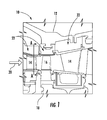
- Fig. 1 provides a simplified cross-section view of a portion of a turbine 10 according to one embodiment of the present invention.
- the turbine 10 may include stationary and rotating components surrounded by a casing 12.
- the stationary components may include, for example, stationary nozzles or stator vanes 14 attached to the casing 12.
- the rotating components may include, for example, rotating blades 16 attached to a rotor 18.
- a working fluid 20, such as steam, combustion gases, or air flows along a hot gas path through the turbine 10 from left to right as shown in Fig. 1 .
- the first stage of stator vanes 14 accelerates and directs the working fluid 20 onto the first stage of rotating blades 16, causing the first stage of rotating blades 16 and rotor 18 to rotate.
- the working fluid 20 then flows across the second stage of stator vanes 14 which accelerates and redirects the working fluid 20 to the next stage of rotating blades (not shown), and the process repeats for each subsequent stage.
- the radially inward portion of the casing 12 may include a series of shroud segments 22 connected to the casing 12 that circumferentially surround and define the hot gas path to reduce the amount of working fluid 20 that bypasses the stator vanes 14 or rotating blades 16.
- shroud or “shroud segment” may encompass and include virtually any static or stationary hardware in the hot gas path exposed to the temperatures and pressures associated with the working fluid 20.
- the shroud segments 22 are located radially outward of the stator vanes 14 and rotating blades 16, while in other particular embodiments the shroud segments 22 may also be located radially inward of the stator vanes 14 and/or rotating blades 16.
- Figs. 2 and 3 provide axial cross-section views of adjacent shroud segments 22 shown in Fig. 1 taken along line A-A according to various embodiments of the present invention.
- the shroud segments 22 are located radially outward of the stator vanes 14, and the gas path is below the shroud segments 22 and between the rotating blades shown in Figs. 2 and 3 .
- the shroud segments 22 have adjacent surfaces 24, and each adjacent surface 24 may have a slot 26, indent, or groove that extends at least partially into the surface 24.
- slot As used herein, the terms “slot”, “indent”, and “groove” are meant to be interchangeable and encompass or include any channel, crevice, notch, or indent defined in the surface 24 of the shroud segments 22.
- a barrier 28, seal, pin, or other structure may be positioned inside the slots 26 and extend between the slots 26 in the adjacent surfaces 24 to flexibly hold the shroud segments 22 in place while also minimizing or preventing working fluid 20 from escaping from the gas path between the adjacent shrouds 22.
- the barrier 28 may be formed from ceramic, alloy steels, or other suitable materials capable of continuous exposure to the temperatures and pressures associated with the gas path.
- the barrier 28 may have a substantially flat surface 30 facing the gas path and in contact with each slot 26. In this manner, the contact between the flat surface 30 of the barrier 28 and the slot 26 enhances a fluid seal that reduces and/or prevents the working fluid 20 from escaping or leaking from the gas path.
- the barrier 28 has a dimension 32 that is larger inside the slots 26 than between the shroud segments 22 to enhance the seal between the barrier 28 and the slots 26.
- One or more shroud segments 22 may include a fluid port 34 through the shroud segment 22.
- the fluid port 34 may provide fluid communication through the shroud segment 22 to the slots 26.
- a pressurized fluid such as compressed air, an inert gas, or steam may be supplied through the shroud segment 22 to the slot 26 to flow over the barrier 28 in the slots 26 and between the shroud segments 22 to provide convective and/or film cooling.
- a fluid passage or bypass channel 36 between the barrier 28 and one or more slots 26 may provide fluid communication to allow the pressurized fluid to flow past the barrier 28 and into the gas path.
- the fluid passage or bypass channel 36 is generally illustrated as extending beneath the barrier 28 substantially perpendicular to a fluid flow (into the page in Figs. 2 and 3 ) in the gas path.
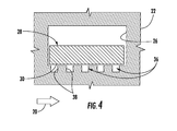
- Figs. 4-6 provide side cross-section views of the shroud segment 22 shown in Fig. 2 taken along line B-B to illustrate various embodiments of the fluid passage or bypass channel 36 within the scope of the present invention.
- the fluid passage or bypass channel 36 includes a plurality of uniformly spaced grooves 38 in the slot 26.
- the grooves 38 allow the pressurized fluid to flow between the substantially flat surface 30 of the barrier 28 and the slot 26 to convectively remove heat from the barrier 28 and/or shroud segment 22.
- the pressurized fluid As the pressurized fluid exits the slot 26 of the shroud segment 22 and enters the gas path, the pressurized fluid provides a layer of film cooling to the barrier 28 and/or shroud segment 22.
- the fluid passage or bypass channel 36 has an arcuate shape 40 in the slot 26 to reduce contact points between the barrier 28 and the slot 26, thereby enhancing convective and film cooling to the barrier 28 as the pressurized fluid flows between the barrier 28 and the slot 26 and into the gas path.
- the fluid passage or bypass channel 36 may have various shapes and sizes, and the present invention is not limited to any particular shape or size of the fluid passage or bypass channel 36 unless specifically recited in the claims.
- Fig. 6 illustrates yet another embodiment in which the barrier 28 includes a plurality of sections 42 that extend generally parallel between the slots 26 in the adjacent surfaces 24.
- the grooves 38 in the fluid passage or bypass channel 36 have decreasing widths and/or depths in the slot 26 in the direction of the working fluid 20 flow in the gas path.
- the deeper and wider grooves 38 permit additional pressurized fluid to flow between the barrier 28 and slot 26 to provide additional convective cooling to the upstream portion of the shroud segments 22 and barrier 28 while also providing increased film cooling across the barrier 28 and shroud segment 22 as the pressurized fluid flows into the gas path.
- the particular width and depth of the grooves 38 may vary according to the location of the shroud segments 22 in the gas path.
- the various embodiments shown in Figs. 1-6 may also provide a method for sealing the gas path in the turbine 10.
- the method may include placing the barrier 28 between slots 26 in adjacent surfaces 24 of adjacent shroud segments 22 and flowing the pressurized fluid between the barrier 28 and one or more slots 26 to the gas path in the turbine 10 so that the pressurized fluid flows through one or more fluid passages or bypass channels 36 in the one or more slots 26.
- the method may include flowing the pressurized fluid through the grooves 38 in one or more slots 26 and/or flowing the pressurized fluid through the fluid port 34 in one or more shroud segments 22.
Landscapes
- Engineering & Computer Science (AREA)
- Mechanical Engineering (AREA)
- General Engineering & Computer Science (AREA)
- Turbine Rotor Nozzle Sealing (AREA)
Abstract
Description
- The present disclosure generally involves a device and method for sealing a gas path in a turbine.
- Turbines are widely used in a variety of aviation, industrial, and power generation applications to perform work. Each turbine generally includes alternating stages of peripherally mounted stator vanes and rotating blades. The stator vanes may be attached to a stationary component such as a casing that surrounds the turbine, and the rotating blades may be attached to a rotor located along an axial centerline of the turbine. A compressed working fluid, such as steam, combustion gases, or air, flows along a gas path through the turbine to produce work. The stator vanes accelerate and direct the compressed working fluid onto the subsequent stage of rotating blades to impart motion to the rotating blades, thus turning the rotor and performing work.
- Compressed working fluid that leaks around or bypasses the stator vanes or rotating blades reduces the efficiency of the turbine.
U.S. Patent 4,902,198 describes an apparatus for film cooling that includes inner and outer shroud segments circumferentially arranged along a gas path. Strip seals seated in slots between adjacent shroud segments reduce the amount of compressed working fluid that escapes from the gas path between adjacent shroud segments. In addition, holes in the shroud segments and intermittent reliefs in the strip seals provide a fluid passage across the strip seals and into the gas path. In this manner, a pressurized fluid may be supplied through the holes, across the reliefs, and into the gas path to prevent leakage from the gas path while also providing film cooling to the strip seals. However, the reliefs in the strip seals weaken the strip seals, possibly leading to premature failure, increased maintenance, and/or foreign material being released into the gas path. As a result, continued improvements in sealing devices and methods for sealing the gas path in a turbine would be useful. - Aspects and advantages of the invention are set forth below in the following description, or may be obvious from the description, or may be learned through practice of the invention.
- One aspect of the present invention is a device for sealing a gas path in a turbine that includes a first shroud segment and a slot in a surface of the first shroud segment. A barrier extends inside the slot, and a bypass channel in the slot provides fluid communication between the barrier and the slot to the gas path in the turbine.
- Another aspect of the present invention is a device for sealing a gas path in a turbine that includes a first shroud segment that has a first slot and a second shroud segment adjacent to the first shroud segment, wherein the second shroud segment has a second slot. A barrier extends from inside the first slot to inside the second slot, and the barrier has a substantially flat surface facing the gas path and in contact with each of the first and second slots. A first fluid passage to the gas path in the turbine is between the barrier and the first slot.
- The present invention also includes a method for sealing a gas path in a turbine. The method includes placing a barrier between a first slot in a first shroud segment and a second slot in a second shroud segment and flowing a fluid between the barrier and the first slot to the gas path in the turbine, wherein the fluid flows through a first bypass channel in the first slot.
- Those of ordinary skill in the art will better appreciate the features and aspects of such embodiments, and others, upon review of the specification.
- Embodiments of the present invention will now be described, by way of example only, with reference to the accompanying drawings in which:
-
Fig. 1 is a side cross-section view of an exemplary turbine within the scope of the present invention; -
Fig. 2 is an axial cross-section view of adjacent shroud segments shown inFig. 1 taken along line A-A according to one embodiment; -
Fig. 3 is an axial cross-section view of adjacent shroud segments shown inFig. 1 taken along line A-A according to an alternate embodiment; -
Fig. 4 is a side cross-section view of the shroud segment shown inFig. 2 taken along line B-B according to one embodiment; -
Fig. 5 is a side cross-section view of the shroud segment shown inFig. 2 taken along line B-B according to an alternate embodiment; and -
Fig. 6 is a side cross-section view of the shroud segment shown inFig. 2 taken along line B-B according to another embodiment. - Reference will now be made in detail to present embodiments of the invention, one or more examples of which are illustrated in the accompanying drawings. The detailed description uses numerical and letter designations to refer to features in the drawings. Like or similar designations in the drawings and description have been used to refer to like or similar parts of the invention. As used herein, the terms "first", "second", and "third" may be used interchangeably to distinguish one component from another and are not intended to signify location or importance of the individual components.
- Each example is provided by way of explanation of the invention, not limitation of the invention. In fact, it will be apparent to those skilled in the art that modifications and variations can be made in the present invention without departing from the scope or spirit thereof. For instance, features illustrated or described as part of one embodiment may be used on another embodiment to yield a still further embodiment. Thus, it is intended that the present invention covers such modifications and variations as come within the scope of the appended claims and their equivalents.
- Various embodiments of the present invention include a device and method for sealing a gas path in a turbine. In particular embodiments, a barrier between adjacent shroud segments may prevent a compressed working fluid from freely flowing between the shroud segments and out of the gas path. The barrier may extend from inside slots formed in adjacent surfaces of the shroud segments. One or more of the shroud segments may include a fluid port and/or a fluid passage or bypass channel between the barrier and the slot. A pressurized fluid may be supplied through the fluid port to flow between the barrier and the slot and into the gas path to prevent leakage from the gas path while also providing convective and/or film cooling to the slot and barrier. Although exemplary embodiments of the present invention will be described generally in the context of a gas path in a turbine, one of ordinary skill in the art will readily appreciate that embodiments of the present invention may be applied to any gas path containing a pressurized fluid.
-
Fig. 1 provides a simplified cross-section view of a portion of aturbine 10 according to one embodiment of the present invention. As shown inFig. 1 , theturbine 10 may include stationary and rotating components surrounded by acasing 12. The stationary components may include, for example, stationary nozzles orstator vanes 14 attached to thecasing 12. The rotating components may include, for example, rotatingblades 16 attached to arotor 18. A workingfluid 20, such as steam, combustion gases, or air, flows along a hot gas path through theturbine 10 from left to right as shown inFig. 1 . The first stage of stator vanes 14 accelerates and directs the workingfluid 20 onto the first stage of rotatingblades 16, causing the first stage of rotatingblades 16 androtor 18 to rotate. The workingfluid 20 then flows across the second stage ofstator vanes 14 which accelerates and redirects the workingfluid 20 to the next stage of rotating blades (not shown), and the process repeats for each subsequent stage. - As shown in
Fig. 1 , the radially inward portion of thecasing 12 may include a series ofshroud segments 22 connected to thecasing 12 that circumferentially surround and define the hot gas path to reduce the amount of workingfluid 20 that bypasses thestator vanes 14 or rotatingblades 16. As used herein, the terms "shroud" or "shroud segment" may encompass and include virtually any static or stationary hardware in the hot gas path exposed to the temperatures and pressures associated with the workingfluid 20. For example, in the particular embodiment shown inFig. 1 , theshroud segments 22 are located radially outward of thestator vanes 14 and rotatingblades 16, while in other particular embodiments theshroud segments 22 may also be located radially inward of thestator vanes 14 and/or rotatingblades 16. -
Figs. 2 and3 provide axial cross-section views ofadjacent shroud segments 22 shown inFig. 1 taken along line A-A according to various embodiments of the present invention. In each view, theshroud segments 22 are located radially outward of thestator vanes 14, and the gas path is below theshroud segments 22 and between the rotating blades shown inFigs. 2 and3 . As shown, theshroud segments 22 haveadjacent surfaces 24, and eachadjacent surface 24 may have aslot 26, indent, or groove that extends at least partially into thesurface 24. As used herein, the terms "slot", "indent", and "groove" are meant to be interchangeable and encompass or include any channel, crevice, notch, or indent defined in thesurface 24 of theshroud segments 22. Abarrier 28, seal, pin, or other structure may be positioned inside theslots 26 and extend between theslots 26 in theadjacent surfaces 24 to flexibly hold theshroud segments 22 in place while also minimizing or preventing workingfluid 20 from escaping from the gas path between theadjacent shrouds 22. Thebarrier 28 may be formed from ceramic, alloy steels, or other suitable materials capable of continuous exposure to the temperatures and pressures associated with the gas path. - As shown in both
Figs. 2 and3 , thebarrier 28 may have a substantiallyflat surface 30 facing the gas path and in contact with eachslot 26. In this manner, the contact between theflat surface 30 of thebarrier 28 and theslot 26 enhances a fluid seal that reduces and/or prevents the workingfluid 20 from escaping or leaking from the gas path. In the particular embodiment shown inFig. 3 , thebarrier 28 has adimension 32 that is larger inside theslots 26 than between theshroud segments 22 to enhance the seal between thebarrier 28 and theslots 26. - One or
more shroud segments 22 may include afluid port 34 through theshroud segment 22. Thefluid port 34 may provide fluid communication through theshroud segment 22 to theslots 26. In this manner, a pressurized fluid such as compressed air, an inert gas, or steam may be supplied through theshroud segment 22 to theslot 26 to flow over thebarrier 28 in theslots 26 and between theshroud segments 22 to provide convective and/or film cooling. Alternately or in addition, a fluid passage orbypass channel 36 between thebarrier 28 and one ormore slots 26 may provide fluid communication to allow the pressurized fluid to flow past thebarrier 28 and into the gas path. InFigs. 2 and3 , the fluid passage orbypass channel 36 is generally illustrated as extending beneath thebarrier 28 substantially perpendicular to a fluid flow (into the page inFigs. 2 and3 ) in the gas path. -
Figs. 4-6 provide side cross-section views of theshroud segment 22 shown inFig. 2 taken along line B-B to illustrate various embodiments of the fluid passage orbypass channel 36 within the scope of the present invention. In the particular embodiment shown inFig. 4 , the fluid passage orbypass channel 36 includes a plurality of uniformly spacedgrooves 38 in theslot 26. Thegrooves 38 allow the pressurized fluid to flow between the substantiallyflat surface 30 of thebarrier 28 and theslot 26 to convectively remove heat from thebarrier 28 and/orshroud segment 22. As the pressurized fluid exits theslot 26 of theshroud segment 22 and enters the gas path, the pressurized fluid provides a layer of film cooling to thebarrier 28 and/orshroud segment 22. In the particular embodiment shown inFig. 5 , the fluid passage orbypass channel 36 has anarcuate shape 40 in theslot 26 to reduce contact points between thebarrier 28 and theslot 26, thereby enhancing convective and film cooling to thebarrier 28 as the pressurized fluid flows between thebarrier 28 and theslot 26 and into the gas path. One of ordinary skill in the art will readily appreciate that the fluid passage orbypass channel 36 may have various shapes and sizes, and the present invention is not limited to any particular shape or size of the fluid passage orbypass channel 36 unless specifically recited in the claims. -
Fig. 6 illustrates yet another embodiment in which thebarrier 28 includes a plurality ofsections 42 that extend generally parallel between theslots 26 in the adjacent surfaces 24. In addition, thegrooves 38 in the fluid passage orbypass channel 36 have decreasing widths and/or depths in theslot 26 in the direction of the workingfluid 20 flow in the gas path. The deeper andwider grooves 38 permit additional pressurized fluid to flow between thebarrier 28 andslot 26 to provide additional convective cooling to the upstream portion of theshroud segments 22 andbarrier 28 while also providing increased film cooling across thebarrier 28 andshroud segment 22 as the pressurized fluid flows into the gas path. The particular width and depth of thegrooves 38 may vary according to the location of theshroud segments 22 in the gas path. - The various embodiments shown in
Figs. 1-6 may also provide a method for sealing the gas path in theturbine 10. The method may include placing thebarrier 28 betweenslots 26 inadjacent surfaces 24 ofadjacent shroud segments 22 and flowing the pressurized fluid between thebarrier 28 and one ormore slots 26 to the gas path in theturbine 10 so that the pressurized fluid flows through one or more fluid passages orbypass channels 36 in the one ormore slots 26. In particular embodiments, the method may include flowing the pressurized fluid through thegrooves 38 in one ormore slots 26 and/or flowing the pressurized fluid through thefluid port 34 in one ormore shroud segments 22. - This written description uses examples to disclose the invention, including the best mode, and also to enable any person skilled in the art to practice the invention, including making and using any devices or systems and performing any incorporated methods. The patentable scope of the invention is defined by the claims, and may include other examples that occur to those skilled in the art. Such other examples are intended to be within the scope of the claims if they include structural elements that do not differ from the literal language of the claims, or if they include equivalent structural elements with insubstantial differences from the literal languages of the claims.
Claims (15)
- A device for sealing a gas path in a turbine (10), comprising:a. a first shroud segment (22);b. a slot (26) in a surface of said first shroud segment (22);c. a barrier (28) extending inside said slot (26); andd. a bypass channel (36) in said slot (26), wherein said bypass channel (36) provides fluid communication between said barrier (28) and said slot (26) to the gas path in the turbine (10).
- The device as in claim 1, further comprising a second shroud segment (22) adjacent to said first shroud segment (22), wherein said first and second shroud segments (22) have adjacent surfaces (24).
- The device as in claim 1 or 2, wherein said barrier (28) comprises a plurality of sections (42) that extends between said slot (26).
- The device as in any of claims 1 to 3, wherein said bypass channel (36) extends substantially perpendicular to a fluid flow in the gas path in the turbine (10).
- The device as in any of claims 1 to 4, wherein said bypass channel (36) comprises a plurality of uniformly spaced grooves (38) in said slot (26).
- The device as in any of claims 1 to 5, wherein said bypass channel (36) has an arcuate shape (40).
- The device as in any preceding claim, further comprising a fluid port (34) through said first shroud segment (22) to said slot (26) in said first shroud segment (22).
- The device of any of claims 2 to 7, wherein the second shroud segment has a second slot (26); and wherein the barrier (28) extending from inside said first slot (26) to inside said second slot (26), wherein said barrier (28) has a substantially flat surface (30) facing the gas path and in contact with each of said first (26) and second slots (26).
- The device as in claim 8, wherein said barrier (28) has a dimension that is larger inside said first and second slots (22) than between said first and second shroud segments (22).
- The device as in claim 8 or 9, wherein said the bypass channel (36) extends in the direction of said second shroud segment (22).
- The device as in any of claims 8 to 10, further comprising a second bypass channel between said barrier (28) and said second slot (26) to the gas path in the turbine (10).
- A method for sealing a gas path in a turbine (10), comprising:a. placing a barrier (28) between a first slot in a first shroud segment (22) and a second slot (26) in a second shroud segment (22); andb. flowing a fluid (20) between said barrier (28) and said first slot (22) to the gas path in the turbine (10), wherein said fluid (20) flows through a first bypass channel (36) in said first slot (22).
- The method as in claim 12, further comprising flowing said fluid (20) through a plurality of grooves (38) in said first slot (26).
- The method as in claim 12 or 13, further comprising flowing said fluid (20) through a fluid port (34) in said first shroud segment (22) to said first slot (26) in said first shroud segment (22).
- The method as in any of claims 12 to 14, further comprising flowing the fluid (20) between said barrier (28) and said second slot (26) to the gas path in the turbine (10), wherein said fluid flows through a second bypass channel (36) in said second slot (26).
Applications Claiming Priority (1)
| Application Number | Priority Date | Filing Date | Title |
|---|---|---|---|
| US13/343,911 US20130177383A1 (en) | 2012-01-05 | 2012-01-05 | Device and method for sealing a gas path in a turbine |
Publications (1)
| Publication Number | Publication Date |
|---|---|
| EP2620597A1 true EP2620597A1 (en) | 2013-07-31 |
Family
ID=47678512
Family Applications (1)
| Application Number | Title | Priority Date | Filing Date |
|---|---|---|---|
| EP12199011.3A Withdrawn EP2620597A1 (en) | 2012-01-05 | 2012-12-21 | Device and method for sealing a gas path in a turbine |
Country Status (5)
| Country | Link |
|---|---|
| US (1) | US20130177383A1 (en) |
| EP (1) | EP2620597A1 (en) |
| JP (1) | JP2013139806A (en) |
| CN (1) | CN103195499A (en) |
| RU (1) | RU2012158308A (en) |
Cited By (3)
| Publication number | Priority date | Publication date | Assignee | Title |
|---|---|---|---|---|
| US9920652B2 (en) | 2015-02-09 | 2018-03-20 | United Technologies Corporation | Gas turbine engine having section with thermally isolated area |
| US10287905B2 (en) | 2013-11-11 | 2019-05-14 | United Technologies Corporation | Segmented seal for gas turbine engine |
| US10634055B2 (en) | 2015-02-05 | 2020-04-28 | United Technologies Corporation | Gas turbine engine having section with thermally isolated area |
Families Citing this family (6)
| Publication number | Priority date | Publication date | Assignee | Title |
|---|---|---|---|---|
| US9416675B2 (en) * | 2014-01-27 | 2016-08-16 | General Electric Company | Sealing device for providing a seal in a turbomachine |
| US10458264B2 (en) | 2015-05-05 | 2019-10-29 | United Technologies Corporation | Seal arrangement for turbine engine component |
| CN111936725B (en) * | 2018-03-30 | 2022-08-16 | 西门子能源全球两合公司 | Sealing arrangement between turbine shroud segments |
| US10982559B2 (en) * | 2018-08-24 | 2021-04-20 | General Electric Company | Spline seal with cooling features for turbine engines |
| US11781440B2 (en) * | 2021-03-09 | 2023-10-10 | Rtx Corporation | Scalloped mateface seal arrangement for CMC platforms |
| US12098643B2 (en) * | 2021-03-09 | 2024-09-24 | Rtx Corporation | Chevron grooved mateface seal |
Citations (5)
| Publication number | Priority date | Publication date | Assignee | Title |
|---|---|---|---|---|
| US4902198A (en) | 1988-08-31 | 1990-02-20 | Westinghouse Electric Corp. | Apparatus for film cooling of turbine van shrouds |
| GB2280935A (en) * | 1993-06-12 | 1995-02-15 | Rolls Royce Plc | Cooled sealing strip for nozzle guide vane segments |
| EP0856640A1 (en) * | 1997-01-30 | 1998-08-05 | Societe Nationale D'etude Et De Construction De Moteurs D'aviation "Snecma" | Sealing consisting of stacked strip sliding freely in a slot |
| EP1221539A2 (en) * | 2001-01-09 | 2002-07-10 | Mitsubishi Heavy Industries, Ltd. | Sealing for shrouds of a gas turbine |
| US20060083620A1 (en) * | 2004-10-15 | 2006-04-20 | Siemens Westinghouse Power Corporation | Cooling system for a seal for turbine vane shrouds |
Family Cites Families (10)
| Publication number | Priority date | Publication date | Assignee | Title |
|---|---|---|---|---|
| JPH03213602A (en) * | 1990-01-08 | 1991-09-19 | General Electric Co <Ge> | Self cooling type joint connecting structure to connect contact segment of gas turbine engine |
| US5531457A (en) * | 1994-12-07 | 1996-07-02 | Pratt & Whitney Canada, Inc. | Gas turbine engine feather seal arrangement |
| US5624227A (en) * | 1995-11-07 | 1997-04-29 | General Electric Co. | Seal for gas turbines |
| US6340285B1 (en) * | 2000-06-08 | 2002-01-22 | General Electric Company | End rail cooling for combined high and low pressure turbine shroud |
| EP1286021B1 (en) * | 2001-08-21 | 2010-10-27 | Alstom Technology Ltd | Method of making a groove-like recess and relevant groove-like recess |
| US20040017050A1 (en) * | 2002-07-29 | 2004-01-29 | Burdgick Steven Sebastian | Endface gap sealing for steam turbine diaphragm interstage packing seals and methods of retrofitting |
| US6843479B2 (en) * | 2002-07-30 | 2005-01-18 | General Electric Company | Sealing of nozzle slashfaces in a steam turbine |
| JP2005016324A (en) * | 2003-06-23 | 2005-01-20 | Hitachi Ltd | Seal device and gas turbine |
| US7527472B2 (en) * | 2006-08-24 | 2009-05-05 | Siemens Energy, Inc. | Thermally sprayed conformal seal |
| US8371800B2 (en) * | 2010-03-03 | 2013-02-12 | General Electric Company | Cooling gas turbine components with seal slot channels |
-
2012
- 2012-01-05 US US13/343,911 patent/US20130177383A1/en not_active Abandoned
- 2012-12-21 EP EP12199011.3A patent/EP2620597A1/en not_active Withdrawn
- 2012-12-26 JP JP2012281921A patent/JP2013139806A/en active Pending
- 2012-12-27 RU RU2012158308/06A patent/RU2012158308A/en not_active Application Discontinuation
-
2013
- 2013-01-05 CN CN2013100017031A patent/CN103195499A/en active Pending
Patent Citations (6)
| Publication number | Priority date | Publication date | Assignee | Title |
|---|---|---|---|---|
| US4902198A (en) | 1988-08-31 | 1990-02-20 | Westinghouse Electric Corp. | Apparatus for film cooling of turbine van shrouds |
| EP0357984A1 (en) * | 1988-08-31 | 1990-03-14 | Westinghouse Electric Corporation | Gas turbine with film cooling of turbine vane shrouds |
| GB2280935A (en) * | 1993-06-12 | 1995-02-15 | Rolls Royce Plc | Cooled sealing strip for nozzle guide vane segments |
| EP0856640A1 (en) * | 1997-01-30 | 1998-08-05 | Societe Nationale D'etude Et De Construction De Moteurs D'aviation "Snecma" | Sealing consisting of stacked strip sliding freely in a slot |
| EP1221539A2 (en) * | 2001-01-09 | 2002-07-10 | Mitsubishi Heavy Industries, Ltd. | Sealing for shrouds of a gas turbine |
| US20060083620A1 (en) * | 2004-10-15 | 2006-04-20 | Siemens Westinghouse Power Corporation | Cooling system for a seal for turbine vane shrouds |
Cited By (3)
| Publication number | Priority date | Publication date | Assignee | Title |
|---|---|---|---|---|
| US10287905B2 (en) | 2013-11-11 | 2019-05-14 | United Technologies Corporation | Segmented seal for gas turbine engine |
| US10634055B2 (en) | 2015-02-05 | 2020-04-28 | United Technologies Corporation | Gas turbine engine having section with thermally isolated area |
| US9920652B2 (en) | 2015-02-09 | 2018-03-20 | United Technologies Corporation | Gas turbine engine having section with thermally isolated area |
Also Published As
| Publication number | Publication date |
|---|---|
| US20130177383A1 (en) | 2013-07-11 |
| RU2012158308A (en) | 2014-07-10 |
| CN103195499A (en) | 2013-07-10 |
| JP2013139806A (en) | 2013-07-18 |
Similar Documents
| Publication | Publication Date | Title |
|---|---|---|
| EP2620597A1 (en) | Device and method for sealing a gas path in a turbine | |
| US8870536B2 (en) | Airfoil | |
| EP2716870B1 (en) | Rotor blade and corresponding turbine | |
| EP2613011A1 (en) | System and method for sealing a gas path in a turbine | |
| US7971882B1 (en) | Labyrinth seal | |
| US8870535B2 (en) | Airfoil | |
| US10480338B2 (en) | Bladed rotor arrangement including axial projection | |
| AU2011250790B2 (en) | Gas turbine of the axial flow type | |
| US20150118033A1 (en) | Microchannel exhaust for cooling and/or purging gas turbine segment gaps | |
| EP2586995A2 (en) | Turbine bucket angel wing features for forward cavity flow control and related method | |
| CZ289277B6 (en) | Gas turbine engine cooling and feather seal arrangement | |
| JPH02104902A (en) | gas turbine | |
| US20150118045A1 (en) | Method and systems for providing cooling for a turbine assembly | |
| CN100396884C (en) | End Face Gap Seal and Improvement Method Used for Gas Turbine Diaphragm Interstage Packing Seal | |
| EP3156607A1 (en) | Turbine nozzle with cooling channel coolant distribution plenum | |
| JP6742753B2 (en) | Turbine bucket platform for controlling intrusion loss | |
| EP3156609A1 (en) | Turbine nozzle with cooling channel coolant discharge plenum | |
| KR20090091190A (en) | Turbomachinery, especially gas turbines | |
| EP2492446A2 (en) | A turbine shroud and a method for manufacturing the turbine shroud | |
| EP3064714A1 (en) | Airfoil, corresponding rotor blade and method | |
| US20140044557A1 (en) | Turbine blade and method for cooling the turbine blade | |
| EP3008309B1 (en) | Gas turbine engine flow control device | |
| US20140341720A1 (en) | Seal system including angular features for rotary machine components | |
| US8668439B2 (en) | Inserts for turbine cooling circuit | |
| CA2937316A1 (en) | Seal arrangement for compressor or turbine section of gas turbine engine |
Legal Events
| Date | Code | Title | Description |
|---|---|---|---|
| PUAI | Public reference made under article 153(3) epc to a published international application that has entered the european phase |
Free format text: ORIGINAL CODE: 0009012 |
|
| AK | Designated contracting states |
Kind code of ref document: A1 Designated state(s): AL AT BE BG CH CY CZ DE DK EE ES FI FR GB GR HR HU IE IS IT LI LT LU LV MC MK MT NL NO PL PT RO RS SE SI SK SM TR |
|
| AX | Request for extension of the european patent |
Extension state: BA ME |
|
| 17P | Request for examination filed |
Effective date: 20140131 |
|
| RBV | Designated contracting states (corrected) |
Designated state(s): AL AT BE BG CH CY CZ DE DK EE ES FI FR GB GR HR HU IE IS IT LI LT LU LV MC MK MT NL NO PL PT RO RS SE SI SK SM TR |
|
| RIC1 | Information provided on ipc code assigned before grant |
Ipc: F01D 11/08 20060101ALI20140219BHEP Ipc: F01D 11/00 20060101AFI20140219BHEP |
|
| STAA | Information on the status of an ep patent application or granted ep patent |
Free format text: STATUS: THE APPLICATION IS DEEMED TO BE WITHDRAWN |
|
| 18D | Application deemed to be withdrawn |
Effective date: 20150701 |