EP2620522A2 - Method for producing a ceramic anti-adhesive coating and corresponding item with such an anti-adhesive coating - Google Patents
Method for producing a ceramic anti-adhesive coating and corresponding item with such an anti-adhesive coating Download PDFInfo
- Publication number
- EP2620522A2 EP2620522A2 EP13150709.7A EP13150709A EP2620522A2 EP 2620522 A2 EP2620522 A2 EP 2620522A2 EP 13150709 A EP13150709 A EP 13150709A EP 2620522 A2 EP2620522 A2 EP 2620522A2
- Authority
- EP
- European Patent Office
- Prior art keywords
- stick coating
- coating
- groups
- applying
- ceramic non
- Prior art date
- Legal status (The legal status is an assumption and is not a legal conclusion. Google has not performed a legal analysis and makes no representation as to the accuracy of the status listed.)
- Withdrawn
Links
- 238000000576 coating method Methods 0.000 title claims abstract description 56
- 239000011248 coating agent Substances 0.000 title claims abstract description 47
- 239000000919 ceramic Substances 0.000 title claims abstract description 43
- 230000000181 anti-adherent effect Effects 0.000 title description 3
- 238000004519 manufacturing process Methods 0.000 title description 3
- 238000000034 method Methods 0.000 claims abstract description 30
- 239000002245 particle Substances 0.000 claims abstract description 30
- 238000005260 corrosion Methods 0.000 claims abstract description 26
- 230000007797 corrosion Effects 0.000 claims abstract description 26
- 238000006243 chemical reaction Methods 0.000 claims abstract description 25
- 239000000758 substrate Substances 0.000 claims abstract description 21
- 239000011230 binding agent Substances 0.000 claims abstract description 12
- 239000008199 coating composition Substances 0.000 claims abstract description 12
- 239000011256 inorganic filler Substances 0.000 claims abstract description 12
- 229910003475 inorganic filler Inorganic materials 0.000 claims abstract description 12
- 125000003118 aryl group Chemical group 0.000 claims abstract description 10
- RMAQACBXLXPBSY-UHFFFAOYSA-N silicic acid Chemical compound O[Si](O)(O)O RMAQACBXLXPBSY-UHFFFAOYSA-N 0.000 claims abstract description 10
- 239000007788 liquid Substances 0.000 claims abstract description 9
- 239000002904 solvent Substances 0.000 claims abstract description 9
- 239000000126 substance Substances 0.000 claims abstract description 5
- XLYOFNOQVPJJNP-UHFFFAOYSA-N water Substances O XLYOFNOQVPJJNP-UHFFFAOYSA-N 0.000 claims description 12
- 125000004432 carbon atom Chemical group C* 0.000 claims description 11
- 125000000217 alkyl group Chemical group 0.000 claims description 9
- 125000002887 hydroxy group Chemical group [H]O* 0.000 claims description 9
- 239000003960 organic solvent Substances 0.000 claims description 6
- 229920006393 polyether sulfone Polymers 0.000 claims description 5
- 239000004642 Polyimide Substances 0.000 claims description 4
- 239000004734 Polyphenylene sulfide Substances 0.000 claims description 4
- 229920001721 polyimide Polymers 0.000 claims description 4
- 229920000069 polyphenylene sulfide Polymers 0.000 claims description 4
- 239000004695 Polyether sulfone Substances 0.000 claims description 3
- 238000001035 drying Methods 0.000 claims description 3
- 229920002312 polyamide-imide Polymers 0.000 claims description 3
- 229920000728 polyester Polymers 0.000 claims description 3
- 239000000945 filler Substances 0.000 claims description 2
- 229910052809 inorganic oxide Inorganic materials 0.000 claims description 2
- 150000001247 metal acetylides Chemical class 0.000 claims description 2
- 150000004767 nitrides Chemical class 0.000 claims description 2
- 239000000080 wetting agent Substances 0.000 claims description 2
- 229920002313 fluoropolymer Polymers 0.000 claims 4
- 239000004811 fluoropolymer Substances 0.000 claims 4
- 229910052751 metal Inorganic materials 0.000 abstract description 6
- 239000002184 metal Substances 0.000 abstract description 6
- YCKRFDGAMUMZLT-UHFFFAOYSA-N Fluorine atom Chemical compound [F] YCKRFDGAMUMZLT-UHFFFAOYSA-N 0.000 abstract 2
- 150000001875 compounds Chemical class 0.000 abstract 2
- 238000007739 conversion coating Methods 0.000 abstract 2
- 229910052731 fluorine Inorganic materials 0.000 abstract 2
- 239000011737 fluorine Substances 0.000 abstract 2
- 229920000642 polymer Polymers 0.000 abstract 2
- 239000010410 layer Substances 0.000 description 46
- QTBSBXVTEAMEQO-UHFFFAOYSA-N Acetic acid Chemical compound CC(O)=O QTBSBXVTEAMEQO-UHFFFAOYSA-N 0.000 description 21
- 238000005524 ceramic coating Methods 0.000 description 18
- 238000012360 testing method Methods 0.000 description 16
- 238000005507 spraying Methods 0.000 description 10
- 239000000203 mixture Substances 0.000 description 9
- 229910000831 Steel Inorganic materials 0.000 description 8
- 239000010959 steel Substances 0.000 description 8
- 230000000052 comparative effect Effects 0.000 description 6
- -1 polytetrafluoroethylene Polymers 0.000 description 6
- 229910004298 SiO 2 Inorganic materials 0.000 description 5
- BLRPTPMANUNPDV-UHFFFAOYSA-N Silane Chemical compound [SiH4] BLRPTPMANUNPDV-UHFFFAOYSA-N 0.000 description 5
- 238000001816 cooling Methods 0.000 description 5
- 230000007062 hydrolysis Effects 0.000 description 5
- 238000006460 hydrolysis reaction Methods 0.000 description 5
- 229920001343 polytetrafluoroethylene Polymers 0.000 description 5
- 239000004810 polytetrafluoroethylene Substances 0.000 description 5
- 229910000077 silane Inorganic materials 0.000 description 5
- XPDWGBQVDMORPB-UHFFFAOYSA-N Fluoroform Chemical compound FC(F)F XPDWGBQVDMORPB-UHFFFAOYSA-N 0.000 description 4
- 239000002585 base Substances 0.000 description 4
- 150000001735 carboxylic acids Chemical class 0.000 description 4
- 238000006068 polycondensation reaction Methods 0.000 description 4
- 239000007787 solid Substances 0.000 description 4
- 229910019142 PO4 Inorganic materials 0.000 description 3
- 238000009835 boiling Methods 0.000 description 3
- 238000005520 cutting process Methods 0.000 description 3
- 239000004205 dimethyl polysiloxane Substances 0.000 description 3
- 150000002739 metals Chemical class 0.000 description 3
- NBIIXXVUZAFLBC-UHFFFAOYSA-K phosphate Chemical compound [O-]P([O-])([O-])=O NBIIXXVUZAFLBC-UHFFFAOYSA-K 0.000 description 3
- 239000010452 phosphate Substances 0.000 description 3
- 229920000435 poly(dimethylsiloxane) Polymers 0.000 description 3
- 150000003254 radicals Chemical class 0.000 description 3
- 238000005245 sintering Methods 0.000 description 3
- 229910052725 zinc Inorganic materials 0.000 description 3
- 229910000851 Alloy steel Inorganic materials 0.000 description 2
- 239000004962 Polyamide-imide Substances 0.000 description 2
- DTQVDTLACAAQTR-UHFFFAOYSA-N Trifluoroacetic acid Chemical compound OC(=O)C(F)(F)F DTQVDTLACAAQTR-UHFFFAOYSA-N 0.000 description 2
- 238000005299 abrasion Methods 0.000 description 2
- 229910052784 alkaline earth metal Inorganic materials 0.000 description 2
- 229910045601 alloy Inorganic materials 0.000 description 2
- 239000000956 alloy Substances 0.000 description 2
- 239000007859 condensation product Substances 0.000 description 2
- JHIVVAPYMSGYDF-UHFFFAOYSA-N cyclohexanone Chemical compound O=C1CCCCC1 JHIVVAPYMSGYDF-UHFFFAOYSA-N 0.000 description 2
- 238000010586 diagram Methods 0.000 description 2
- 238000005530 etching Methods 0.000 description 2
- 239000011159 matrix material Substances 0.000 description 2
- 229920001296 polysiloxane Polymers 0.000 description 2
- 238000002360 preparation method Methods 0.000 description 2
- 239000002994 raw material Substances 0.000 description 2
- 238000005488 sandblasting Methods 0.000 description 2
- HBMJWWWQQXIZIP-UHFFFAOYSA-N silicon carbide Chemical compound [Si+]#[C-] HBMJWWWQQXIZIP-UHFFFAOYSA-N 0.000 description 2
- 229910010271 silicon carbide Inorganic materials 0.000 description 2
- 229910001220 stainless steel Inorganic materials 0.000 description 2
- POAOYUHQDCAZBD-UHFFFAOYSA-N 2-butoxyethanol Chemical compound CCCCOCCO POAOYUHQDCAZBD-UHFFFAOYSA-N 0.000 description 1
- CTQNGGLPUBDAKN-UHFFFAOYSA-N O-Xylene Chemical compound CC1=CC=CC=C1C CTQNGGLPUBDAKN-UHFFFAOYSA-N 0.000 description 1
- 239000012790 adhesive layer Substances 0.000 description 1
- 239000002390 adhesive tape Substances 0.000 description 1
- 239000003513 alkali Substances 0.000 description 1
- 150000001342 alkaline earth metals Chemical class 0.000 description 1
- IYRWEQXVUNLMAY-UHFFFAOYSA-N carbonyl fluoride Chemical compound FC(F)=O IYRWEQXVUNLMAY-UHFFFAOYSA-N 0.000 description 1
- 238000009833 condensation Methods 0.000 description 1
- 230000005494 condensation Effects 0.000 description 1
- 229910052593 corundum Inorganic materials 0.000 description 1
- 239000010431 corundum Substances 0.000 description 1
- 238000000354 decomposition reaction Methods 0.000 description 1
- 230000001419 dependent effect Effects 0.000 description 1
- 238000013461 design Methods 0.000 description 1
- QYMFNZIUDRQRSA-UHFFFAOYSA-N dimethyl butanedioate;dimethyl hexanedioate;dimethyl pentanedioate Chemical compound COC(=O)CCC(=O)OC.COC(=O)CCCC(=O)OC.COC(=O)CCCCC(=O)OC QYMFNZIUDRQRSA-UHFFFAOYSA-N 0.000 description 1
- 239000005431 greenhouse gas Substances 0.000 description 1
- 150000004679 hydroxides Chemical class 0.000 description 1
- 239000010954 inorganic particle Substances 0.000 description 1
- 238000011835 investigation Methods 0.000 description 1
- 239000000463 material Substances 0.000 description 1
- 238000013021 overheating Methods 0.000 description 1
- 238000012856 packing Methods 0.000 description 1
- 238000002203 pretreatment Methods 0.000 description 1
- 239000000047 product Substances 0.000 description 1
- 238000007788 roughening Methods 0.000 description 1
- 239000002356 single layer Substances 0.000 description 1
- 238000003980 solgel method Methods 0.000 description 1
- 239000010935 stainless steel Substances 0.000 description 1
- 238000010998 test method Methods 0.000 description 1
- BFKJFAAPBSQJPD-UHFFFAOYSA-N tetrafluoroethene Chemical compound FC(F)=C(F)F BFKJFAAPBSQJPD-UHFFFAOYSA-N 0.000 description 1
- 231100000331 toxic Toxicity 0.000 description 1
- 231100000167 toxic agent Toxicity 0.000 description 1
- 230000002588 toxic effect Effects 0.000 description 1
- 239000008096 xylene Substances 0.000 description 1
Images
Classifications
-
- C—CHEMISTRY; METALLURGY
- C23—COATING METALLIC MATERIAL; COATING MATERIAL WITH METALLIC MATERIAL; CHEMICAL SURFACE TREATMENT; DIFFUSION TREATMENT OF METALLIC MATERIAL; COATING BY VACUUM EVAPORATION, BY SPUTTERING, BY ION IMPLANTATION OR BY CHEMICAL VAPOUR DEPOSITION, IN GENERAL; INHIBITING CORROSION OF METALLIC MATERIAL OR INCRUSTATION IN GENERAL
- C23C—COATING METALLIC MATERIAL; COATING MATERIAL WITH METALLIC MATERIAL; SURFACE TREATMENT OF METALLIC MATERIAL BY DIFFUSION INTO THE SURFACE, BY CHEMICAL CONVERSION OR SUBSTITUTION; COATING BY VACUUM EVAPORATION, BY SPUTTERING, BY ION IMPLANTATION OR BY CHEMICAL VAPOUR DEPOSITION, IN GENERAL
- C23C18/00—Chemical coating by decomposition of either liquid compounds or solutions of the coating forming compounds, without leaving reaction products of surface material in the coating; Contact plating
- C23C18/02—Chemical coating by decomposition of either liquid compounds or solutions of the coating forming compounds, without leaving reaction products of surface material in the coating; Contact plating by thermal decomposition
- C23C18/12—Chemical coating by decomposition of either liquid compounds or solutions of the coating forming compounds, without leaving reaction products of surface material in the coating; Contact plating by thermal decomposition characterised by the deposition of inorganic material other than metallic material
- C23C18/1204—Chemical coating by decomposition of either liquid compounds or solutions of the coating forming compounds, without leaving reaction products of surface material in the coating; Contact plating by thermal decomposition characterised by the deposition of inorganic material other than metallic material inorganic material, e.g. non-oxide and non-metallic such as sulfides, nitrides based compounds
- C23C18/122—Inorganic polymers, e.g. silanes, polysilazanes, polysiloxanes
-
- A—HUMAN NECESSITIES
- A47—FURNITURE; DOMESTIC ARTICLES OR APPLIANCES; COFFEE MILLS; SPICE MILLS; SUCTION CLEANERS IN GENERAL
- A47J—KITCHEN EQUIPMENT; COFFEE MILLS; SPICE MILLS; APPARATUS FOR MAKING BEVERAGES
- A47J36/00—Parts, details or accessories of cooking-vessels
- A47J36/02—Selection of specific materials, e.g. heavy bottoms with copper inlay or with insulating inlay
- A47J36/025—Vessels with non-stick features, e.g. coatings
-
- C—CHEMISTRY; METALLURGY
- C23—COATING METALLIC MATERIAL; COATING MATERIAL WITH METALLIC MATERIAL; CHEMICAL SURFACE TREATMENT; DIFFUSION TREATMENT OF METALLIC MATERIAL; COATING BY VACUUM EVAPORATION, BY SPUTTERING, BY ION IMPLANTATION OR BY CHEMICAL VAPOUR DEPOSITION, IN GENERAL; INHIBITING CORROSION OF METALLIC MATERIAL OR INCRUSTATION IN GENERAL
- C23C—COATING METALLIC MATERIAL; COATING MATERIAL WITH METALLIC MATERIAL; SURFACE TREATMENT OF METALLIC MATERIAL BY DIFFUSION INTO THE SURFACE, BY CHEMICAL CONVERSION OR SUBSTITUTION; COATING BY VACUUM EVAPORATION, BY SPUTTERING, BY ION IMPLANTATION OR BY CHEMICAL VAPOUR DEPOSITION, IN GENERAL
- C23C18/00—Chemical coating by decomposition of either liquid compounds or solutions of the coating forming compounds, without leaving reaction products of surface material in the coating; Contact plating
- C23C18/02—Chemical coating by decomposition of either liquid compounds or solutions of the coating forming compounds, without leaving reaction products of surface material in the coating; Contact plating by thermal decomposition
- C23C18/04—Pretreatment of the material to be coated
-
- C—CHEMISTRY; METALLURGY
- C23—COATING METALLIC MATERIAL; COATING MATERIAL WITH METALLIC MATERIAL; CHEMICAL SURFACE TREATMENT; DIFFUSION TREATMENT OF METALLIC MATERIAL; COATING BY VACUUM EVAPORATION, BY SPUTTERING, BY ION IMPLANTATION OR BY CHEMICAL VAPOUR DEPOSITION, IN GENERAL; INHIBITING CORROSION OF METALLIC MATERIAL OR INCRUSTATION IN GENERAL
- C23C—COATING METALLIC MATERIAL; COATING MATERIAL WITH METALLIC MATERIAL; SURFACE TREATMENT OF METALLIC MATERIAL BY DIFFUSION INTO THE SURFACE, BY CHEMICAL CONVERSION OR SUBSTITUTION; COATING BY VACUUM EVAPORATION, BY SPUTTERING, BY ION IMPLANTATION OR BY CHEMICAL VAPOUR DEPOSITION, IN GENERAL
- C23C18/00—Chemical coating by decomposition of either liquid compounds or solutions of the coating forming compounds, without leaving reaction products of surface material in the coating; Contact plating
- C23C18/02—Chemical coating by decomposition of either liquid compounds or solutions of the coating forming compounds, without leaving reaction products of surface material in the coating; Contact plating by thermal decomposition
- C23C18/12—Chemical coating by decomposition of either liquid compounds or solutions of the coating forming compounds, without leaving reaction products of surface material in the coating; Contact plating by thermal decomposition characterised by the deposition of inorganic material other than metallic material
- C23C18/1204—Chemical coating by decomposition of either liquid compounds or solutions of the coating forming compounds, without leaving reaction products of surface material in the coating; Contact plating by thermal decomposition characterised by the deposition of inorganic material other than metallic material inorganic material, e.g. non-oxide and non-metallic such as sulfides, nitrides based compounds
- C23C18/1208—Oxides, e.g. ceramics
- C23C18/1212—Zeolites, glasses
-
- C—CHEMISTRY; METALLURGY
- C23—COATING METALLIC MATERIAL; COATING MATERIAL WITH METALLIC MATERIAL; CHEMICAL SURFACE TREATMENT; DIFFUSION TREATMENT OF METALLIC MATERIAL; COATING BY VACUUM EVAPORATION, BY SPUTTERING, BY ION IMPLANTATION OR BY CHEMICAL VAPOUR DEPOSITION, IN GENERAL; INHIBITING CORROSION OF METALLIC MATERIAL OR INCRUSTATION IN GENERAL
- C23C—COATING METALLIC MATERIAL; COATING MATERIAL WITH METALLIC MATERIAL; SURFACE TREATMENT OF METALLIC MATERIAL BY DIFFUSION INTO THE SURFACE, BY CHEMICAL CONVERSION OR SUBSTITUTION; COATING BY VACUUM EVAPORATION, BY SPUTTERING, BY ION IMPLANTATION OR BY CHEMICAL VAPOUR DEPOSITION, IN GENERAL
- C23C18/00—Chemical coating by decomposition of either liquid compounds or solutions of the coating forming compounds, without leaving reaction products of surface material in the coating; Contact plating
- C23C18/02—Chemical coating by decomposition of either liquid compounds or solutions of the coating forming compounds, without leaving reaction products of surface material in the coating; Contact plating by thermal decomposition
- C23C18/12—Chemical coating by decomposition of either liquid compounds or solutions of the coating forming compounds, without leaving reaction products of surface material in the coating; Contact plating by thermal decomposition characterised by the deposition of inorganic material other than metallic material
- C23C18/1225—Deposition of multilayers of inorganic material
-
- C—CHEMISTRY; METALLURGY
- C23—COATING METALLIC MATERIAL; COATING MATERIAL WITH METALLIC MATERIAL; CHEMICAL SURFACE TREATMENT; DIFFUSION TREATMENT OF METALLIC MATERIAL; COATING BY VACUUM EVAPORATION, BY SPUTTERING, BY ION IMPLANTATION OR BY CHEMICAL VAPOUR DEPOSITION, IN GENERAL; INHIBITING CORROSION OF METALLIC MATERIAL OR INCRUSTATION IN GENERAL
- C23C—COATING METALLIC MATERIAL; COATING MATERIAL WITH METALLIC MATERIAL; SURFACE TREATMENT OF METALLIC MATERIAL BY DIFFUSION INTO THE SURFACE, BY CHEMICAL CONVERSION OR SUBSTITUTION; COATING BY VACUUM EVAPORATION, BY SPUTTERING, BY ION IMPLANTATION OR BY CHEMICAL VAPOUR DEPOSITION, IN GENERAL
- C23C18/00—Chemical coating by decomposition of either liquid compounds or solutions of the coating forming compounds, without leaving reaction products of surface material in the coating; Contact plating
- C23C18/02—Chemical coating by decomposition of either liquid compounds or solutions of the coating forming compounds, without leaving reaction products of surface material in the coating; Contact plating by thermal decomposition
- C23C18/12—Chemical coating by decomposition of either liquid compounds or solutions of the coating forming compounds, without leaving reaction products of surface material in the coating; Contact plating by thermal decomposition characterised by the deposition of inorganic material other than metallic material
- C23C18/125—Process of deposition of the inorganic material
- C23C18/1254—Sol or sol-gel processing
-
- C—CHEMISTRY; METALLURGY
- C23—COATING METALLIC MATERIAL; COATING MATERIAL WITH METALLIC MATERIAL; CHEMICAL SURFACE TREATMENT; DIFFUSION TREATMENT OF METALLIC MATERIAL; COATING BY VACUUM EVAPORATION, BY SPUTTERING, BY ION IMPLANTATION OR BY CHEMICAL VAPOUR DEPOSITION, IN GENERAL; INHIBITING CORROSION OF METALLIC MATERIAL OR INCRUSTATION IN GENERAL
- C23C—COATING METALLIC MATERIAL; COATING MATERIAL WITH METALLIC MATERIAL; SURFACE TREATMENT OF METALLIC MATERIAL BY DIFFUSION INTO THE SURFACE, BY CHEMICAL CONVERSION OR SUBSTITUTION; COATING BY VACUUM EVAPORATION, BY SPUTTERING, BY ION IMPLANTATION OR BY CHEMICAL VAPOUR DEPOSITION, IN GENERAL
- C23C22/00—Chemical surface treatment of metallic material by reaction of the surface with a reactive liquid, leaving reaction products of surface material in the coating, e.g. conversion coatings, passivation of metals
- C23C22/82—After-treatment
- C23C22/83—Chemical after-treatment
Definitions
- the invention relates to a method for producing a ceramic non-stick coating. Furthermore, the invention relates to an article, in particular a household item or a commodity with such an anti-stick coating.
- non-stick coatings are made from compositions containing polytetrafluoroethylene (PTFE).
- PTFE coatings are known to have a number of disadvantages.
- the preparation processes require a sintering process at a temperature between 360 and 420 ° C. at which parts of the coating composition decompose to form toxic compounds (eg fluorophosgene, tetrafluoroethene or trifluoroacetic acid) ( Nature, Vol. 412, 19, July 2001, p. 321-324 ).
- toxic compounds eg fluorophosgene, tetrafluoroethene or trifluoroacetic acid
- HFC-23 greenhouse gas fluoroform
- the sintering process is an expensive and energy-consuming process due to the high temperatures used.
- PTFE-containing non-stick coatings have insufficient hardness.
- the overheating of the cookware may lead to the release of toxic decomposition products, as mentioned above for the manufacturing process.
- the EP 1 835 002 A2 a non-stick coating of two layers, wherein the first so-called base layer consists of a matrix of a condensation product of the silica sol with an organoalkoxysilane and thereon an upper layer of a matrix of a condensation product of a silica sol with a mixture of an organoalkoxysilane and a fluoroalkoxysilane is applied.
- a ceramic non-stick coating is known, which is obtained by hydrolysis and polycondensation of a silane RSi (OR ') 3 with nanoscale SiO 2 particles, a hydroxy-functional polydimethylsiloxane, a carboxylic acid, water-miscible organic solvents and water.
- these ceramic non-stick coatings have sufficient adhesion to metallic substrates only when the surface is previously roughened. This roughening is usually done by sandblasting with corundum. As an alternative, etching processes as well as a metallic or oxidic thermal spray coating can produce the necessary roughness of the surface.
- Ceramic non-stick coatings made by the sol-gel process also have insufficient corrosion resistance on steel. Of course, this could be avoided by using high-alloy stainless steels, which are more suitable but very expensive.
- the said corrosion resistance is of course a gradual property. If one accordingly accepts a lower corrosion resistance, one can at most - continue to waive high-alloy stainless steel - use corrosion-improved metals.
- US 2007/0036900 A1 describes a method in which a fluoropolymer-free binder with inorganic particles having an average particle size of not more than two microns is applied to a substrate and dried. On the thus applied base layer, the non-stick coating is applied.
- the corrosion resistance is achieved here by the small particle size of the inorganic filler particles, which form a dense packing in the dried coating.
- the roughness of this base layer is not sufficiently large to allow sufficient adhesion of ceramic sol-gel coatings on this base layer.
- the object of the present invention is accordingly to propose a method for applying a non-stick coating, by means of the coating composition both a high corrosion resistance and a good adhesion of a ceramic sol-gel coating on metallic substrates without sandblasting, etching processes or thermal spray coatings is made possible.
- the object is achieved according to the invention by a method according to claim 1, if one wishes a single-layer ceramic non-stick coating or according to claim 2, if one wishes a two-layer non-stick coating.
- a lower corrosion resistance is accepted or a high-alloy steel may be used - one can dispense with the conversion layer and achieve the required corrosion resistance by selecting the substrate - ie a high-alloy steel or corrosion-improved metals.
- the inorganic filler particles used have an average particle size of 9 to 40 microns.
- the mean particle size is defined as the particle size, in a given volume, where 50% of the total volume of the particles has a particle size less than or equal to the specified particle size (d 50 ).
- the mean particle size of the inorganic filler particles used is 9 ⁇ m.
- the inorganic filler particles prevent the shrinkage of the underlayer during drying and produce the necessary roughness to achieve sufficient adhesion to the subsequent ceramic sol-gel coating of the top layer. Too high roughness values lead to loss of gloss of the subsequent ceramic sol-gel coating.
- the roughness R A is between 2 and 3 micrometers.
- the liquid coating composition of the underlayer advantageously contains organic solvents.
- the fluoropolymer-free binder can be dispersed in water or in water-soluble form with the aid of a suitable wetting agent.
- these binders comprise polyethersulfones (PESU) and / or polyphenylene sulfides (PPS) and / or polyimides (PI) and / or polyamide-imides (PAI).
- PESU polyethersulfones
- PPS polyphenylene sulfides
- PI polyimides
- PAI polyamide-imides
- it may comprise silicone-modified polyester.
- the inorganic filler particles are advantageously selected from the group of inorganic oxides, carbides, borides and nitrides and mixtures thereof.
- the inorganic filler particles are advantageously selected from the group of inorganic oxides, carbides, borides and nitrides and mixtures thereof.
- high hardness which contributes to an increased abrasion resistance of the overall layer structure.
- Another object of the invention is achieved by providing an article having a metallic surface as a substrate, a conversion layer, a subbing layer and at least one ceramic non-stick ceramic coating, said layers being formed by the method of the invention.
- Such an article is advantageous as a household or utility object, in particular as a baking pan.
- the solids of the sublayer used in a particularly preferred embodiment is 15-55 wt.%.
- the substrate 1, to which the underlayer 3 is applied consists of a degreased untreated metallic substrate, which is provided with a corrosion-resistant conversion layer 2 by chemical pretreatment, with or without the use of electric current.
- a phosphate-containing conversion layer 2 is applied to the untreated metallic substrate.
- the person skilled in the art is familiar with such conversion layers and the processes for their preparation.
- the metal sheets provided with a corrosion-resistant conversion layer are coated with the underlayer according to the invention in a spraying process and, as indicated in the exemplary embodiments, dried. On the dried cooled bottom layer, the ceramic non-stick coating is sprayed and dried as indicated in the embodiments.
- test panels thus obtained are provided with a 2 mm cross-hatch cut to DIN EN ISO 2409 and 3 times with 3M 8402 tape stuck to the cut grid and pulled off abruptly.
- the test panels are then exposed to the steam of boiling 2.5% aqueous acetic acid for 10 minutes and cooled.
- the cutting grid is covered again 3 times with 3M 8402 tape, pulled off abruptly and the result is assessed.
- the test panels are then exposed for a further 20 minutes to the steam of boiling 2.5% aqueous acetic acid (a total of 30 minutes) and cooled.
- the cutting grid is covered again 3 times with 3M 8402 tape, pulled off abruptly and the result is assessed.
- test panels are then exposed for a further 30 minutes to the steam of boiling 2.5% aqueous acetic acid (60 minutes in total) and cooled.
- the cutting grid is covered again 3 times with 3M 8402 tape, pulled off abruptly and the result is assessed.
- the dry film thickness of the applied ceramic coating was 47 ⁇ m.
- a subbing layer according to the invention according to Table 2 is applied by spraying and dried at 140 ° C for 5 minutes and then at 280 for 20 minutes ° C crosslinked. After cooling, a two-layer ceramic coating is applied to this sublayer.
- Table 2 ⁇ / b> raw material Wt.% Solids% N- methylporrolidone 60 polyether sulfone 10 10 silicon carbide 30 30 TOTAL 100 40
- the dry film thickness of the applied ceramic coating was 22 ⁇ m.
- the dry film thickness of the applied ceramic coating was 64 ⁇ m.
- the dry film thickness of the applied ceramic coating was 26.5 ⁇ m.
- a two-layer ceramic coating is applied directly to a Zn, Mn-phosphated test sheet steel GARDOBOND ® 26S 6800 0C of the Fa. Chemetall GmbH, Frankfurt am Main, Germany, applied by spraying and then dried for 5 minutes at 150 ° C and 20 minutes at 200 ° C branded.
- the dry film thickness of the applied ceramic coating was 13 ⁇ m.
- the ceramic coating dissolves completely when removing the adhesive tape without being exposed to acetic acid.
- a two-layer ceramic coating is applied directly to a & Bonderite ® CC40 of Messrs. Henkel AG & Co KGaA, Dusseldorf, Germany, provided surface of a steel sheet (1.0394) by spraying and then dried for 5 minutes at 150 ° C and 20 minutes at 200 ° C branded.
- the dry film thickness of the applied ceramic coating was 14.5 ⁇ m.
Landscapes
- Chemical & Material Sciences (AREA)
- Engineering & Computer Science (AREA)
- Mechanical Engineering (AREA)
- Metallurgy (AREA)
- General Chemical & Material Sciences (AREA)
- Chemical Kinetics & Catalysis (AREA)
- Organic Chemistry (AREA)
- Materials Engineering (AREA)
- Physics & Mathematics (AREA)
- Thermal Sciences (AREA)
- Inorganic Chemistry (AREA)
- Ceramic Engineering (AREA)
- Food Science & Technology (AREA)
- Dispersion Chemistry (AREA)
- Laminated Bodies (AREA)
- Application Of Or Painting With Fluid Materials (AREA)
- Paints Or Removers (AREA)
Abstract
Description
Die Erfindung betrifft ein Verfahren zum Herstellen einer keramischen Antihaftbeschichtung. Weiterhin betrifft die Erfindung einen Artikel, insbsondere einen Haushaltsgegenstand oder einen Gebrauchsgegenstand mit einer solchen Antifhaftbeschichtung.The invention relates to a method for producing a ceramic non-stick coating. Furthermore, the invention relates to an article, in particular a household item or a commodity with such an anti-stick coating.
Herkömmlich werden Antihaft-Beschichtungen aus Polytetrafluorethylen (PTFE) enthaltenden Zusammensetzungen hergestellt. Solche PTFE-Beschichtungen weisen jedoch bekanntermassen eine Reihe von Nachteilen auf. Einerseits erfordern die Herstellverfahren einen Sinterprozess bei einer Temperatur zwischen 360 und 420 °C, bei dem sich Teile der Beschichtungszusammensetzung unter Bildung toxischer Verbindungen (z.B. Fluorphosgen, Tetrafluorethen oder Trifluoressigsäure) zersetzen (
Auf Grund dieser Nachteile von PTFE-haltigen Beschichtungen wurden in den letzten Jahren verschiedene PTFE-freie keramische Beschichtungen auf Sol-Gel Basis entwickelt.Due to these disadvantages of PTFE-containing coatings, various PTFE-free ceramic coatings based on sol-gel have been developed in recent years.
So offenbart die
In der
Aus der
Diese keramischen Antihaft-Beschichtungen besitzen auf metallischen Substraten jedoch nur dann ausreichende Haftung, wenn die Oberfläche vorher aufgeraut wird. Dieses Aufrauen erfolgt normalerweise durch Sandstrahlen mit Korund. Als Alternative können Ätzprozesse sowie eine metallische oder oxidische thermische Spritzschicht die notwendige Rauheit der Oberfläche erzeugen.However, these ceramic non-stick coatings have sufficient adhesion to metallic substrates only when the surface is previously roughened. This roughening is usually done by sandblasting with corundum. As an alternative, etching processes as well as a metallic or oxidic thermal spray coating can produce the necessary roughness of the surface.
Keramische Antihaft-Beschichtungen, die nach dem Sol-Gel Verfahren hergestellt werden, weisen darüber hinaus auf Stahl nur unzureichende Korrosionsbeständigkeit auf. Dies könnte man selbstverständlich durch den Einsatz von hochlegierten Edelstählen vermeiden, die besser geeignet aber sehr teuer sind.Ceramic non-stick coatings made by the sol-gel process also have insufficient corrosion resistance on steel. Of course, this could be avoided by using high-alloy stainless steels, which are more suitable but very expensive.
Die genannte Korrosionsbeständigkeit ist selbstverständlich eine graduelle Eigenschaft. Wenn man dementsprechend eine geringere Korrosionsbeständigkeit in Kauf nimmt, kann man allenfalls - weiterhin unter Verzicht auf hochlegierten Edelstahl - korrosionsverbesserte Metalle verwenden.The said corrosion resistance is of course a gradual property. If one accordingly accepts a lower corrosion resistance, one can at most - continue to waive high-alloy stainless steel - use corrosion-improved metals.
Übliche Vorbehandlungsverfahren, um das Korrosionsverhalten von Metallen zu verbessern, wie das Aufbringen von Phosphatschichten oder phosphatfreie Umwandlungsschichten wie Bonderite-NT-1 zeigen als Untergrund für keramische Sol-Gel Schichten unzureichende Rauigkeiten und somit zeigen die keramischen Sol-Gel Schichten keine ausreichende Haftung auf dem vorbehandelten Untergrund.Conventional pretreatment methods to improve the corrosion behavior of metals, such as the application of phosphate coatings or phosphate-free Conversion layers such as Bonderite NT-1 show insufficient roughness as a substrate for ceramic sol-gel layers and thus the ceramic sol-gel layers do not show sufficient adhesion to the pretreated substrate.
Aufgabe der vorliegenden Erfindung ist es dementsprechend, ein Verfahren zum Aufbringen einer Antihaftbeschichtung vorzuschlagen, mit dem mittels der Beschichtungszusammensetzung sowohl eine hohe Korrosionsbeständigkeit als auch eine gute Haftung einer keramischen Sol-Gel Beschichtung auf metallischen Substraten ohne Sandstrahlen, Ätzprozesse oder thermische Spritzschichten ermöglicht wird.The object of the present invention is accordingly to propose a method for applying a non-stick coating, by means of the coating composition both a high corrosion resistance and a good adhesion of a ceramic sol-gel coating on metallic substrates without sandblasting, etching processes or thermal spray coatings is made possible.
Die Aufgabe wird erfindungsgemäss gelöst durch ein Verfahren nach Anspruch 1, wenn man eine einschichtige keramische Antihaftbeschichtung wünscht oder nach Anspruch 2, wenn man eine zweischichtige Antihaftbeschichtung wünscht.The object is achieved according to the invention by a method according to
In einer abgewandelten Form des Verfahrens - wenn eine geringere Korrosionsbeständigkeit in Kauf genommen wird oder ein hochlegierter Stahl zum Einsatz kommen darf - kann man auf die Umwandlungsschicht verzichten und die geforderte Korrosionsbeständigkeit durch die Auswahl des Substrates - also ein hochlegierter Stahl oder korrosionsverbesserte Metalle - erreichen.In a modified form of the process - if a lower corrosion resistance is accepted or a high-alloy steel may be used - one can dispense with the conversion layer and achieve the required corrosion resistance by selecting the substrate - ie a high-alloy steel or corrosion-improved metals.
Die verwendeten anorganischen Füllstoffpartikel besitzen eine mittlere Teilchengrösse von 9 bis 40 µm. Die mittlere Teilchengrösse ist definiert als die Teilchengrösse, in einem gegebenen Volumen, bei der 50% des gesamten Volumens der Partikel eine Teilchengrösse besitzt, die kleiner oder gleich der angegebenen Teilchengrösse ist (d50). In einer besonders bevorzugten Ausführungsform beträgt die mittlere Teilchengrösse der verwendeten anorganischen Füllstoffpartikel 9 µm.The inorganic filler particles used have an average particle size of 9 to 40 microns. The mean particle size is defined as the particle size, in a given volume, where 50% of the total volume of the particles has a particle size less than or equal to the specified particle size (d 50 ). In a particularly preferred embodiment, the mean particle size of the inorganic filler particles used is 9 μm.
Die anorganischen Füllstoffpartikel verhindern das Schrumpfen der Unterschicht bei der Trocknung und erzeugen die nötige Rauigkeit um eine ausreichende Haftung zur nachfolgenden keramischen Sol-Gel Beschichtung der Oberschicht zu erreichen. Zu hohe Rauheitswerte führen zu Glanzverlusten der nachfolgenden keramischen Sol-Gel Beschichtung. In einer besonders bevorzugten Ausführungsform beträgt die Rauigkeit RA zwischen 2 und 3 Mikrometer.The inorganic filler particles prevent the shrinkage of the underlayer during drying and produce the necessary roughness to achieve sufficient adhesion to the subsequent ceramic sol-gel coating of the top layer. Too high roughness values lead to loss of gloss of the subsequent ceramic sol-gel coating. In a particularly preferred embodiment, the roughness R A is between 2 and 3 micrometers.
Vorteilhafte Ausgestaltungen des erfindungsgemässen Verfahrens sind in den abhängigen Patentansprüchen angegeben.Advantageous embodiments of the inventive method are given in the dependent claims.
Vorteilhaft ist es, wenn die Unterschicht getrocknet wird. Dabei ist es besonders vorteilhaft, wenn das Trocknen der Unterschicht ein Einbrennprozess ist. Weiterhin als vorteilhaft hat sich herausgestellt, wenn die Trockenfilmschichtdicke der Unterschicht zwischen 9 und 40 µm liegt. Die flüssige Beschichtungszusammensetzung der Unterschicht enthält vorteilhafterweise organische Lösungsmittel. Das fluorpolymerfreie Bindemittel kann mit Hilfe eines geeigneten Netzmittels in Wasser dispergiert oder in wasserlöslicher Form vorliegen. Vorteilhafterweise umfassen diese Bindemittel Polyethersulfone (PESU) und/oder Polyphenylensulfide (PPS) und/oder Polyimide (PI) und/oder Polyamidimide (PAI). Weiterhin kann es silikonmodifizierten Polyester umfassen.It is advantageous if the lower layer is dried. It is particularly advantageous if the drying of the lower layer is a baking process. Furthermore, it has proved to be advantageous if the dry film thickness of the lower layer is between 9 and 40 μm. The liquid coating composition of the underlayer advantageously contains organic solvents. The fluoropolymer-free binder can be dispersed in water or in water-soluble form with the aid of a suitable wetting agent. Advantageously, these binders comprise polyethersulfones (PESU) and / or polyphenylene sulfides (PPS) and / or polyimides (PI) and / or polyamide-imides (PAI). Furthermore, it may comprise silicone-modified polyester.
Die anorganischen Füllstoffpartikel werden vorteilhaft aus der Gruppe anorganischer Oxide, Carbide, Boride und Nitride und Mischungen davon ausgewählt. Neben der Reduzierung des Schrumpfens der Unterschicht besitzen die genannten Füllstoffe meist hohe Härte, was zu einer erhöhten Abriebbeständigkeit des Gesamtschichtaufbaus beiträgt.The inorganic filler particles are advantageously selected from the group of inorganic oxides, carbides, borides and nitrides and mixtures thereof. In addition to the reduction of the shrinkage of the lower layer possess the fillers mentioned usually high hardness, which contributes to an increased abrasion resistance of the overall layer structure.
Eine weitere Aufgabe der Erfindung wird mit dem Bereitstellen eines Artikel mit einer metallischen Oberfläche als Substrat, einer Umwandlungsschicht, einer Unterschicht und zumindest einer keramischen einer keramischen Antihaftbeschichtung gelöst, wobei die genannten Schichten mittels des erfindungsgemässen Verfahrens ausgebildet bzw. appliziert sind. Vorteilhaft ist ein solcher Artikel als Haushalt- oder Gebrauchsgegenstand, insbesondere als Backform.Another object of the invention is achieved by providing an article having a metallic surface as a substrate, a conversion layer, a subbing layer and at least one ceramic non-stick ceramic coating, said layers being formed by the method of the invention. Such an article is advantageous as a household or utility object, in particular as a baking pan.
Der Festkörper der verwendeten Unterschicht beträgt in einer besonders bevorzugten Ausführungsform 15-55 Gew.%.The solids of the sublayer used in a particularly preferred embodiment is 15-55 wt.%.
Die vorbenannten sowie die beanspruchten und in den nachfolgenden Ausführungsbeispielen beschriebenen, erfindungsgemäss zu verwendenden Elemente unterliegen in ihrer Grösse, Formgestaltung, Materialverwendung und ihrer technischen Konzeption keinen besonderen Ausnahmebedingungen, so dass die in dem jeweiligen Anwendungsgebiet bekannten Auswahlkriterien uneingeschränkt Anwendung finden können.The above-mentioned as well as the claimed and described in the following embodiments, according to the invention to be used elements are subject to their size, shape design, material usage and their technical conception no special conditions of exception, so that the well-known in the respective field of application selection criteria can apply without restriction.
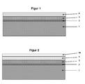
Ausführungsbeispiele der Erfindung werden nachfolgend anhand von Zeichnungen näher beschrieben, dabei zeigen:
Figur 1- ein Schichtaufbaudiagramm gemäss einem ersten Ausführungsbeispiel mit einer keramischen Antihaftschicht;
Figur 2- ein Schichtaufbaudiagramm gemäss einem weiteren Ausführungsbeispiel mit zwei keramischen Antihaftschichten.
- FIG. 1
- a layer structure diagram according to a first embodiment with a ceramic non-stick layer;
- FIG. 2
- a layer structure diagram according to another embodiment with two ceramic anti-adhesive layers.
Das Substrat 1, auf das die Unterschicht 3 aufgebracht wird, besteht aus einem entfetteten unbehandelten metallischen Substrat, das durch chemische Vorbehandlung - mit oder ohne Anwendung von elektrischem Strom - mit einer möglichst korrosionsbeständigen Umwandlungsschicht 2 versehen wird. In einer besonders bevorzugten Ausführungsform wird auf das unbehandelte metallische Substrat eine phosphathaltige Umwandlungsschicht 2 aufgebracht. Dem Fachmann sind solche Umwandlungsschichten und die Verfahren zu deren Herstellung geläufig.The
Die direkte Applikation von keramischen Sol-Gel Beschichtungen 4 auf korrosionsbeständige phosphathaltige oder phosphatfreie Umwandlungsschichten zeigen keine ausreichende Haftung der keramischen Schicht auf der Umwandlungsschicht, da die Rauigkeit dieser Umwandlungsschicht zu niedrig ist.The direct application of ceramic sol-
Eine erste keramische Schicht wird im vorliegenden Ausführungsbeispiel durch Hydrolyse und Polykondensation einer wässrigen Mischung erhalten wobei die Mischung enthält
- 10 - 70 Gew.-% eines Silans der allgemeinen Formel (I)
(I) RSiX3
in der die Gruppen X hydrolysierbare Gruppen oder Hydroxylgruppen sind und die Reste R für Alkyl- oder Arylgruppen mit 1 bis 6 Kohlenstoffatomen stehen,
- 8 bis 21 Gew.-% nanoskaliger SiO2-Partikel
- 0
bis 2 Gew.-% eines Polydimethylsiloxans der allgemeinen Formel (II)
(II) HO-[Si(CH3)2-O]n-H
in der n eine Zahl zwischen 2 und 170 darstellt,
- 0,1
bis 2 Gew.-%einer Carbonsäure mit 1bis 4 Kohlenstoffatomen, - 7 bis 50 Gew.-% Wasser
- 10 bis 60 Gew.-% mit Wasser mischbare organische Lösemittel, wobei die zuvor genannten Gewichtsanteile zusammen 100 Gew.-% ergeben.
10 to 70% by weight of a silane of the general formula (I)
(I) RSiX 3
in which the groups X are hydrolyzable groups or hydroxyl groups and the radicals R are alkyl or aryl groups having 1 to 6 carbon atoms,
- 8 to 21 wt .-% nanoscale SiO 2 particles
- 0 to 2% by weight of a polydimethylsiloxane of the general formula (II)
(II) HO- [Si (CH 3 ) 2 -O] n -H
where n represents a number between 2 and 170,
- 0.1 to 2% by weight of a carboxylic acid having 1 to 4 carbon atoms,
- 7 to 50 wt .-% water
- From 10 to 60% by weight of water-miscible organic solvents, wherein the abovementioned proportions by weight together amount to 100% by weight.
Eine zweischichtige keramische Beschichtung wird - in einem alternativen Ausführungsbeispiel - erhalten durch Hydrolyse und Polykondensation einer wässrigen Mischung erhalten, wobei die Mischung enthält
- 10 - 70 Gew.-% eines Silans der allgemeinen Formel (I)
RSiX3 (I)
in der die Gruppen X hydrolysierbare Gruppen oder Hydroxylgruppen sind und die Reste R für Alkyl- oder Arylgruppen stehen,
- 8 bis 21 Gew.-% nanoskaliger SiO2-Partikel
- 0,1
bis 2 Gew.-%einer Carbonsäure mit 1bis 4 Kohlenstoffatomen, - 7 bis 50 Gew.-% Wasser
- 10 bis 60 Gew.-% mit Wasser mischbare organische Lösemittel und dann durch Hydrolyse und Polykondensation einer wässrigen Mischung, wobei diese Mischung enthält
- 10 - 70 Gew.-% eines Silans der allgemeinen Formel (I)
RSiX3 (I)
in der die Gruppen X hydrolysierbare Gruppen oder Hydroxylgruppen sind und die Reste R für Alkyl-oder Arylgruppen mit 1 bis 6 Kohlenstoffatomen stehen, - 8 bis 21 Gew.-% nanoskaliger SiO2-Partikel
- 0
bis 2 Gew.-% eines Polydimethylsiloxans der allgemeinen Formel (II)
HO-[Si(CH3)2-O]n-H (II)
in der n eine Zahl zwischen 2 und 170 darstellt, - 0,1
bis 2 Gew.-%einer Carbonsäure mit 1bis 4 Kohlenstoffatomen, - 7 bis 50 Gew.-% Wasser
- 10 bis 60 Gew.-% mit Wasser mischbare organische Lösemittel, wobei die zuvor genannten Gewichtsanteile zusammen 100 Gew.-% ergeben.
- 10-70% by weight of a silane of the general formula (I)
RSiX 3 (I)
in which the groups X are hydrolyzable groups or hydroxyl groups and the radicals R stand for alkyl or aryl groups,
- 8 to 21 wt .-% nanoscale SiO 2 particles
- 0.1 to 2% by weight of a carboxylic acid having 1 to 4 carbon atoms,
- 7 to 50 wt .-% water
- From 10 to 60% by weight of water-miscible organic solvents and then by hydrolysis and polycondensation of an aqueous mixture, this mixture containing
- 10-70% by weight of a silane of the general formula (I)
RSiX 3 (I)
in which the groups X are hydrolyzable groups or hydroxyl groups and the radicals R are alkyl or aryl groups having 1 to 6 carbon atoms, - 8 to 21 wt .-% nanoscale SiO 2 particles
- 0 to 2% by weight of a polydimethylsiloxane of the general formula (II)
HO- [Si (CH 3 ) 2 -O] n -H (II)
where n represents a number between 2 and 170, - 0.1 to 2% by weight of a carboxylic acid having 1 to 4 carbon atoms,
- 7 to 50 wt .-% water
- From 10 to 60% by weight of water-miscible organic solvents, wherein the abovementioned proportions by weight together amount to 100% by weight.
Die mit einer korrosionsbeständigen Umwandlungsschicht versehenen Metallbleche werden mit der erfindungsgemässen Unterschicht in einem Sprühprozess beschichtet und, wie in den Ausführungsbeispielen angegeben, getrocknet. Auf die getrocknete abgekühlte Unterschicht wird die keramische Antihaft-Beschichtung aufgesprüht und wie in den Ausführungsbeispielen angegeben, getrocknet.The metal sheets provided with a corrosion-resistant conversion layer are coated with the underlayer according to the invention in a spraying process and, as indicated in the exemplary embodiments, dried. On the dried cooled bottom layer, the ceramic non-stick coating is sprayed and dried as indicated in the embodiments.
Die so erhaltenen Prüfbleche werden mit einem 2 mm Gitterschnitt nach DIN EN ISO 2409 versehen und 3mal mit 3M 8402 Klebeband auf dem Schnittgitter beklebt und ruckartig abgerissen. Die Prüfbleche werden dann 10 Minuten dem Dampf kochender 2,5%iger wässriger Essigsäure ausgesetzt und abgekühlt. Das Schnittgitter wird erneut 3mal mit 3M 8402 Klebeband beklebt, ruckartig abgerissen und das Ergebnis beurteilt. Anschliessend werden die Prüfbleche weitere 20 Minuten dem Dampf kochender 2,5%iger wässriger Essigsäure ausgesetzt (insgesamt 30 Minuten) und abgekühlt. Das Schnittgitter wird erneut 3mal mit 3M 8402 Klebeband beklebt, ruckartig abgerissen und das Ergebnis beurteilt.The test panels thus obtained are provided with a 2 mm cross-hatch cut to
Anschliessend werden die Prüfbleche weitere 30 Minuten dem Dampf kochender 2,5%iger wässriger Essigsäure ausgesetzt (insgesamt 60 Minuten) und abgekühlt. Das Schnittgitter wird erneut 3mal mit 3M 8402 Klebeband beklebt, ruckartig abgerissen und das Ergebnis beurteilt.The test panels are then exposed for a further 30 minutes to the steam of boiling 2.5% aqueous acetic acid (60 minutes in total) and cooled. The cutting grid is covered again 3 times with 3M 8402 tape, pulled off abruptly and the result is assessed.
Auf ein Zn,Mn-phosphatiertes Prüf-Stahlblech GARDOBOND® 26S 6800 0C der Fa. Chemetall GmbH, Frankfurt a.M., Deutschland, wird durch Sprühen eine erfindungsgemässe Unterschicht nach Tabelle 1 aufgetragen und 5 Minuten bei 150 °C getrocknet und anschliessend 20 Minuten bei 280 °C vernetzt. Nach Abkühlen wird auf diese Unterschicht eine zweischichtige keramische Beschichtung aufgetragen.
Die Trockenfilmschichtdicke der aufgebrachten keramischen Beschichtung betrug hierbei 47 µm. Die mittlere Rauheit RA der GARDOBOND® 26S 6800 0C Oberfläche betrug RA=1,56 µm.The dry film thickness of the applied ceramic coating was 47 μm. The average roughness R A of GARDOBOND ® 26S was 6800 0C surface R A = 1.56 microns.
Die Ergebnisse der Haftungs- und Korrosionsprüfungen sind in Tabelle 3 zusammengefasst.The results of the adhesion and corrosion tests are summarized in Table 3 .
Auf ein Zn,Mn-phosphatiertes Prüf-Stahlblech GARDOBOND® 26S 6800 0C der Fa. Chemetall GmbH, Frankfurt a.M., Deutschland, wird durch Sprühen eine erfindungsgemässe Unterschicht nach Tabelle 2 aufgetragen und 5 Minuten bei 140 °C getrocknet und anschliessend 20 Minuten bei 280 °C vernetzt. Nach Abkühlen wird auf diese Unterschicht eine zweischichtige keramische Beschichtung aufgetragen.
Die Trockenfilmschichtdicke der aufgebrachten keramischen Beschichtung betrug hierbei 22 µm. Die mittlere Rauheit RA der GARDOBOND® 26S 6800 0C Oberfläche betrug RA=1,56 µm.The dry film thickness of the applied ceramic coating was 22 μm. The average roughness R A of GARDOBOND ® 26S was 6800 0C surface R A = 1.56 microns.
Die Ergebnisse der Haftungs- und Korrosionsprüfungen sind in Tabelle 3 zusammengefasst.The results of the adhesion and corrosion tests are summarized in Table 3 .
Auf ein Stahlblech (1.0394), welches mit BONDERITE® CC40 der Fa. Henkel AG & Co KGaA, Düsseldorf, Deutschland, vorbehandelt wurde, wird durch Sprühen eine erfindungsgemässe Unterschicht nach Tabelle 1 aufgetragen und 5 Minuten bei 150 °C getrocknet und anschliessend 20 Minuten bei 280 °C vernetzt. Nach Abkühlen wird auf diese Unterschicht eine zweischichtige keramische Beschichtung aufgetragen.To a steel sheet (1.0394) which Bonderite ® CC40 of Messrs. Henkel AG & Co. KGaA, Dusseldorf, Germany, was pretreated, is applied by spraying an inventive underlayer according to Table 1 and dried for 5 minutes at 150 ° C and then 20 minutes crosslinked at 280 ° C. After cooling, a two-layer ceramic coating is applied to this sublayer.
Die Trockenfilmschichtdicke der aufgebrachten keramischen Beschichtung betrug hierbei 64 µm. Die mittlere Rauheit RA der BONDERITE CC40® Oberfläche betrug RA=1,15 µm.The dry film thickness of the applied ceramic coating was 64 μm. The average roughness R A of the surface area was BONDERITE CC40 ® R A = 1.15 microns.
Die Ergebnisse der Haftungs- und Korrosionsprüfungen sind in Tabelle 3 zusammengefasst.The results of the adhesion and corrosion tests are summarized in Table 3 .
Auf ein Fe-phosphatiertes Prüf-Stahlblech GARDOBOND® WH 60 0C der Fa. Chemetall GmbH, Frankfurt a.M., Deutschland, wird durch Sprühen eine erfindungsgemässe Unterschicht nach Tabelle 1 aufgetragen und 5 Minuten bei 150 °C getrocknet und anschliessend 20 Minuten bei 280 °C vernetzt. Nach Abkühlen wird auf diese Unterschicht eine zweischichtige keramische Beschichtungaufgetragen.On a Fe-phosphated test steel sheet GARDOBOND ® WH 60 0C from. Fa. Chemetall GmbH, Frankfurt aM, Germany, by spraying an inventive under layer according to Table 1 is applied and dried for 5 minutes at 150 ° C and then at 280 ° C for 20 minutes networked. After cooling, a two-layer ceramic coating is applied to this underlayer.
Die Trockenfilmschichtdicke der aufgebrachten keramischen Beschichtung betrug hierbei 26.5 µm. Die mittlere Rauheit RA der GARDOBOND® WH 60 0C Oberfläche betrug RA=2.66 µm.The dry film thickness of the applied ceramic coating was 26.5 μm. The average roughness R A of GARDOBOND ® WH 60 0C surface area was A = R 2.66 microns.
Die Ergebnisse der Haftungs- und Korrosionsprüfungen sind in Tabelle 3 zusammengefasst.The results of the adhesion and corrosion tests are summarized in Table 3 .
Auf ein Zn -phosphatiertes Prüf-Stahlblech GARDOBOND® 26S 60 OC der Fa. Chemetall GmbH, Frankfurt a.M., Deutschland, wird durch Sprühen eine erfindungsgemässe Unterschicht nach Tabelle 1 aufgetragen und 5 Minuten bei 150 °C getrocknet und anschliessend 20 Minuten bei 280 °C vernetzt. Nach Abkühlen wird auf diese Unterschicht eine zweischichtige keramische Beschichtung aufgetragen. Die Trockenfilmschichtdicke der aufgebrachten keramischen Beschichtung betrug hierbei 31 µm. Die mittlere Rauheit RA der GARDOBOND® 26S 60 OC Oberfläche betrug RA=2.72 µm.On a Zn-phosphated test steel GARDOBOND ® 26S 60 OC Fa. Chemetall GmbH, Frankfurt aM, Germany, by spraying an inventive underlayer according to Table 1 is applied and dried for 5 minutes at 150 ° C and then at 280 ° C for 20 minutes networked. After cooling, a two-layer ceramic coating is applied to this sublayer. The dry film thickness of the applied ceramic coating was 31 μm. The average roughness R A of GARDOBOND ® 26S was 60 OC surface R A = 2.72 microns.
Die Ergebnisse der Haftungs- und Korrosionsprüfungen sind in Tabelle 3 zusammengefasst.The results of the adhesion and corrosion tests are summarized in Table 3 .
Eine zweischichtige keramische Beschichtung wird direkt auf ein Zn,Mn-phosphatiertes Prüf-Stahlblech GARDOBOND® 26S 6800 0C der Fa. Chemetall GmbH, Frankfurt a.M., Deutschland, durch Sprühen aufgetragen und anschliessend 5 Minuten bei 150 °C getrocknet und 20 Minuten bei 200 °C eingebrannt.A two-layer ceramic coating is applied directly to a Zn, Mn-phosphated test sheet steel GARDOBOND ® 26S 6800 0C of the Fa. Chemetall GmbH, Frankfurt am Main, Germany, applied by spraying and then dried for 5 minutes at 150 ° C and 20 minutes at 200 ° C branded.
Die Trockenfilmschichtdicke der aufgebrachten keramischen Beschichtung betrug hierbei 13 µm. Die mittlere Rauheit RA der GARDOBOND® 26S 6800 0C Oberfläche betrug RA=1,56 µm.The dry film thickness of the applied ceramic coating was 13 μm. The average roughness R A of GARDOBOND ® 26S was 6800 0C surface R A = 1.56 microns.
Die keramische Beschichtung löst sich beim Abziehen des Klebebandes vollständig ab, ohne der Essigsäure ausgesetzt worden zu sein.The ceramic coating dissolves completely when removing the adhesive tape without being exposed to acetic acid.
Eine zweischichtige keramische Beschichtung wird direkt auf eine mit BONDERITE® CC40 der Fa. Henkel AG & Co KGaA, Düsseldorf, Deutschland, versehene Oberfläche eines Stahlbleches (1.0394) durch Sprühen aufgetragen und anschliessend 5 Minuten bei 150 °C getrocknet und 20 Minuten bei 200 °C eingebrannt.A two-layer ceramic coating is applied directly to a & Bonderite ® CC40 of Messrs. Henkel AG & Co KGaA, Dusseldorf, Germany, provided surface of a steel sheet (1.0394) by spraying and then dried for 5 minutes at 150 ° C and 20 minutes at 200 ° C branded.
Die Trockenfilmschichtdicke der aufgebrachten keramischen Beschichtung betrug hierbei 14,5 µm. Die mittlere Rauheit RA der mit BONDERITE® CC40 behandelten Oberfläche betrug RA=1,15µm.The dry film thickness of the applied ceramic coating was 14.5 μm. The average roughness R A of patients treated with BONDERITE ® CC40 surface area was A =
Die Ergebnisse der Haftungs- und Korrosionsprüfungen sind in Tabelle 3 zusammengefasst.
Claims (14)
RSiX3 (I)
in der die Gruppen X hydrolysierbare Gruppen oder Hydroxylgruppen sind und die Reste R für Alkyl- oder Arylgruppen mit 1 bis 6 Kohlenstoffatomen stehen, ausgebildet wird.
RSiX 3 (I)
in which the groups X are hydrolyzable groups or hydroxyl groups and the radicals R are alkyl or aryl groups having 1 to 6 carbon atoms is formed.
(I) RSiX3
in der die Gruppen X hydrolysierbare Gruppen oder Hydroxylgruppen sind und die Reste R für Alkyl- oder Arylgruppen mit 1 bis 6 Kohlenstoffatomen stehen, ausgebildet wird, und
(I) RSiX3
in der die Gruppen X hydrolysierbare Gruppen oder Hydroxylgruppen sind und die Reste R für Alkyl- oder Arylgruppen mit 1 bis 6 Kohlenstoffatomen stehen, ausgebildet wird.
(I) RSiX 3
in which the groups X are hydrolyzable groups or hydroxyl groups and the radicals R are alkyl or aryl groups having 1 to 6 carbon atoms, is formed, and
(I) RSiX 3
in which the groups X are hydrolyzable groups or hydroxyl groups and the radicals R are alkyl or aryl groups having 1 to 6 carbon atoms is formed.
(I) RSiX3
in der die Gruppen X hydrolysierbare Gruppen oder Hydroxylgruppen sind und die Reste R für Alkyl- oder Arylgruppen mit 1 bis 6 Kohlenstoffatomen stehen, ausgebildet wird.
(I) RSiX 3
in which the groups X are hydrolyzable groups or hydroxyl groups and the radicals R are alkyl or aryl groups having 1 to 6 carbon atoms is formed.
(I) RSiX3
in der die Gruppen X hydrolysierbare Gruppen oder Hydroxylgruppen sind und die Reste R für Alkyl- oder Arylgruppen mit 1 bis 6 Kohlenstoffatomen stehen, ausgebildet wird, und
(I) RSiX3
in der die Gruppen X hydrolysierbare Gruppen oder Hydroxylgruppen sind und die Reste R für Alkyl- oder Arylgruppen mit 1 bis 6 Kohlenstoffatomen stehen, ausgebildet wird.
(I) RSiX 3
in which the groups X are hydrolyzable groups or hydroxyl groups and the radicals R are alkyl or aryl groups having 1 to 6 carbon atoms, is formed, and
(I) RSiX 3
in which the groups X are hydrolyzable groups or hydroxyl groups and the radicals R are alkyl or aryl groups having 1 to 6 carbon atoms is formed.
Priority Applications (1)
| Application Number | Priority Date | Filing Date | Title |
|---|---|---|---|
| EP13150709.7A EP2620522A3 (en) | 2012-01-25 | 2013-01-09 | Method for producing a ceramic anti-adhesive coating and corresponding item with such an anti-adhesive coating |
Applications Claiming Priority (2)
| Application Number | Priority Date | Filing Date | Title |
|---|---|---|---|
| EP12152554.7A EP2620521A1 (en) | 2012-01-25 | 2012-01-25 | Method for producing a ceramic anti-adhesive coating and corresponding item with such an anti-adhesive coating |
| EP13150709.7A EP2620522A3 (en) | 2012-01-25 | 2013-01-09 | Method for producing a ceramic anti-adhesive coating and corresponding item with such an anti-adhesive coating |
Publications (2)
| Publication Number | Publication Date |
|---|---|
| EP2620522A2 true EP2620522A2 (en) | 2013-07-31 |
| EP2620522A3 EP2620522A3 (en) | 2013-08-21 |
Family
ID=47458836
Family Applications (2)
| Application Number | Title | Priority Date | Filing Date |
|---|---|---|---|
| EP12152554.7A Withdrawn EP2620521A1 (en) | 2012-01-25 | 2012-01-25 | Method for producing a ceramic anti-adhesive coating and corresponding item with such an anti-adhesive coating |
| EP13150709.7A Withdrawn EP2620522A3 (en) | 2012-01-25 | 2013-01-09 | Method for producing a ceramic anti-adhesive coating and corresponding item with such an anti-adhesive coating |
Family Applications Before (1)
| Application Number | Title | Priority Date | Filing Date |
|---|---|---|---|
| EP12152554.7A Withdrawn EP2620521A1 (en) | 2012-01-25 | 2012-01-25 | Method for producing a ceramic anti-adhesive coating and corresponding item with such an anti-adhesive coating |
Country Status (1)
| Country | Link |
|---|---|
| EP (2) | EP2620521A1 (en) |
Cited By (3)
| Publication number | Priority date | Publication date | Assignee | Title |
|---|---|---|---|---|
| CN110338667A (en) * | 2018-04-02 | 2019-10-18 | 佛山市顺德区美的电热电器制造有限公司 | Inner Pot and Cooking Utensils |
| CN114158948A (en) * | 2021-12-17 | 2022-03-11 | 武汉苏泊尔炊具有限公司 | Non-stick pan and manufacturing method thereof |
| CN115820116A (en) * | 2022-12-27 | 2023-03-21 | 武汉苏泊尔炊具有限公司 | Modified ceramic paint, composite coating, preparation method of modified ceramic paint and composite coating, and cooker |
Citations (3)
| Publication number | Priority date | Publication date | Assignee | Title |
|---|---|---|---|---|
| US20070036900A1 (en) | 2005-08-12 | 2007-02-15 | Yuqing Liu | Process for improving the corrosion resistance of a non-stick coating on a substrate |
| EP1835002A2 (en) | 2006-03-14 | 2007-09-19 | Cerasol Hong Kong Limited | Non-stick ceramic coating composition and process |
| EP2177580B1 (en) | 2008-10-16 | 2011-01-19 | Looser Holding AG | Non-stick coatings |
-
2012
- 2012-01-25 EP EP12152554.7A patent/EP2620521A1/en not_active Withdrawn
-
2013
- 2013-01-09 EP EP13150709.7A patent/EP2620522A3/en not_active Withdrawn
Patent Citations (3)
| Publication number | Priority date | Publication date | Assignee | Title |
|---|---|---|---|---|
| US20070036900A1 (en) | 2005-08-12 | 2007-02-15 | Yuqing Liu | Process for improving the corrosion resistance of a non-stick coating on a substrate |
| EP1835002A2 (en) | 2006-03-14 | 2007-09-19 | Cerasol Hong Kong Limited | Non-stick ceramic coating composition and process |
| EP2177580B1 (en) | 2008-10-16 | 2011-01-19 | Looser Holding AG | Non-stick coatings |
Non-Patent Citations (1)
| Title |
|---|
| NATURE, vol. 412, no. 19, July 2001 (2001-07-01), pages 321 - 324 |
Cited By (4)
| Publication number | Priority date | Publication date | Assignee | Title |
|---|---|---|---|---|
| CN110338667A (en) * | 2018-04-02 | 2019-10-18 | 佛山市顺德区美的电热电器制造有限公司 | Inner Pot and Cooking Utensils |
| CN114158948A (en) * | 2021-12-17 | 2022-03-11 | 武汉苏泊尔炊具有限公司 | Non-stick pan and manufacturing method thereof |
| CN115820116A (en) * | 2022-12-27 | 2023-03-21 | 武汉苏泊尔炊具有限公司 | Modified ceramic paint, composite coating, preparation method of modified ceramic paint and composite coating, and cooker |
| CN115820116B (en) * | 2022-12-27 | 2024-02-27 | 武汉苏泊尔炊具有限公司 | Modified ceramic coating, composite coating, preparation method of modified ceramic coating and cooker |
Also Published As
| Publication number | Publication date |
|---|---|
| EP2620521A1 (en) | 2013-07-31 |
| EP2620522A3 (en) | 2013-08-21 |
Similar Documents
| Publication | Publication Date | Title |
|---|---|---|
| DE60021464T2 (en) | Substrate based on silicon with a thermal barrier coating | |
| DE69210000T2 (en) | Process for protecting a composite material against oxidation and products protected in this way | |
| DE60017823T2 (en) | Method for applying a barrier layer to a silicon-containing substrate and article produced by this method | |
| EP2177580B1 (en) | Non-stick coatings | |
| WO2008119751A1 (en) | Coating for vapor condensers | |
| WO2007095927A2 (en) | Corrosion-resistant substrate and method for its production | |
| EP2743320B1 (en) | Multistage process for coating steel prior to thermoforming | |
| CH709779A2 (en) | Lacquer dispersion for the production of non-stick coatings on surfaces. | |
| DE69007622T2 (en) | NON-ADHESIVE COATING SYSTEM WITH TWO THIN BASIC COATINGS, THE FIRST BASED ON POLYSILOXANE. | |
| EP2620522A2 (en) | Method for producing a ceramic anti-adhesive coating and corresponding item with such an anti-adhesive coating | |
| DE4129600C2 (en) | METHOD FOR IMPREGNATING POROUS CARBON BODIES TO PROTECT AGAINST OXIDATION AND USE OF THESE CARBON BODIES | |
| EP2834392B1 (en) | Cr (vi)-free anti-corrosion layers or adhesive layers which contain a solution comprising phosphate ions and metal powder, the metal powder being at least partially coated with si or si alloys | |
| CH648869A5 (en) | METHOD FOR PRODUCING INSULATING COATS ON STEEL PRODUCTS. | |
| EP2158275A1 (en) | Hydrophobic surface coating for electronic and electro-technical components and uses thereof | |
| EP1927275B1 (en) | Printing template of an smt process and method of coating it | |
| EP1484372B1 (en) | Coated aluminium foil and process of producing same | |
| DE10127494B4 (en) | High temperature stable inorganic boron nitride layers | |
| DE102015116916A1 (en) | Coating, coating system and coating process | |
| EP0718254A2 (en) | Anti-oxidative, abrasion-resistant protective coating for SiC bodies | |
| DE102004002303B4 (en) | A method of making a coated carbon / carbon composite and coated carbon / carbon composite produced thereafter | |
| DE10018671C2 (en) | Process for producing a hydrophobic surface of objects made of silicate ceramic materials and object with a hydrophobic surface | |
| EP1943319A1 (en) | Production of coated substrates | |
| DE202007007303U1 (en) | Corrosion resistant substrate | |
| EP0036558A1 (en) | Coated metal article and method of manufacturing the same | |
| EP1173523B1 (en) | Method for producing a layered material and layered material thus obtained |
Legal Events
| Date | Code | Title | Description |
|---|---|---|---|
| PUAL | Search report despatched |
Free format text: ORIGINAL CODE: 0009013 |
|
| PUAI | Public reference made under article 153(3) epc to a published international application that has entered the european phase |
Free format text: ORIGINAL CODE: 0009012 |
|
| AK | Designated contracting states |
Kind code of ref document: A2 Designated state(s): AL AT BE BG CH CY CZ DE DK EE ES FI FR GB GR HR HU IE IS IT LI LT LU LV MC MK MT NL NO PL PT RO RS SE SI SK SM TR |
|
| AX | Request for extension of the european patent |
Extension state: BA ME |
|
| AK | Designated contracting states |
Kind code of ref document: A3 Designated state(s): AL AT BE BG CH CY CZ DE DK EE ES FI FR GB GR HR HU IE IS IT LI LT LU LV MC MK MT NL NO PL PT RO RS SE SI SK SM TR |
|
| AX | Request for extension of the european patent |
Extension state: BA ME |
|
| RIC1 | Information provided on ipc code assigned before grant |
Ipc: C23C 18/12 20060101AFI20130715BHEP Ipc: B05D 5/08 20060101ALI20130715BHEP Ipc: C23C 18/04 20060101ALI20130715BHEP Ipc: A47J 36/02 20060101ALI20130715BHEP Ipc: C23C 22/00 20060101ALI20130715BHEP |
|
| STAA | Information on the status of an ep patent application or granted ep patent |
Free format text: STATUS: THE APPLICATION IS DEEMED TO BE WITHDRAWN |
|
| 18D | Application deemed to be withdrawn |
Effective date: 20140222 |