EP2620512A1 - Turbine induction temper system - Google Patents
Turbine induction temper system Download PDFInfo
- Publication number
- EP2620512A1 EP2620512A1 EP13153268.1A EP13153268A EP2620512A1 EP 2620512 A1 EP2620512 A1 EP 2620512A1 EP 13153268 A EP13153268 A EP 13153268A EP 2620512 A1 EP2620512 A1 EP 2620512A1
- Authority
- EP
- European Patent Office
- Prior art keywords
- induction
- temper
- control system
- temperature sensor
- turbine
- Prior art date
- Legal status (The legal status is an assumption and is not a legal conclusion. Google has not performed a legal analysis and makes no representation as to the accuracy of the status listed.)
- Granted
Links
Images


Classifications
-
- C—CHEMISTRY; METALLURGY
- C21—METALLURGY OF IRON
- C21D—MODIFYING THE PHYSICAL STRUCTURE OF FERROUS METALS; GENERAL DEVICES FOR HEAT TREATMENT OF FERROUS OR NON-FERROUS METALS OR ALLOYS; MAKING METAL MALLEABLE, e.g. BY DECARBURISATION OR TEMPERING
- C21D1/00—General methods or devices for heat treatment, e.g. annealing, hardening, quenching or tempering
- C21D1/34—Methods of heating
- C21D1/42—Induction heating
-
- C—CHEMISTRY; METALLURGY
- C21—METALLURGY OF IRON
- C21D—MODIFYING THE PHYSICAL STRUCTURE OF FERROUS METALS; GENERAL DEVICES FOR HEAT TREATMENT OF FERROUS OR NON-FERROUS METALS OR ALLOYS; MAKING METAL MALLEABLE, e.g. BY DECARBURISATION OR TEMPERING
- C21D1/00—General methods or devices for heat treatment, e.g. annealing, hardening, quenching or tempering
- C21D1/06—Surface hardening
- C21D1/09—Surface hardening by direct application of electrical or wave energy; by particle radiation
- C21D1/10—Surface hardening by direct application of electrical or wave energy; by particle radiation by electric induction
-
- C—CHEMISTRY; METALLURGY
- C21—METALLURGY OF IRON
- C21D—MODIFYING THE PHYSICAL STRUCTURE OF FERROUS METALS; GENERAL DEVICES FOR HEAT TREATMENT OF FERROUS OR NON-FERROUS METALS OR ALLOYS; MAKING METAL MALLEABLE, e.g. BY DECARBURISATION OR TEMPERING
- C21D9/00—Heat treatment, e.g. annealing, hardening, quenching or tempering, adapted for particular articles; Furnaces therefor
- C21D9/0068—Heat treatment, e.g. annealing, hardening, quenching or tempering, adapted for particular articles; Furnaces therefor for particular articles not mentioned below
-
- F—MECHANICAL ENGINEERING; LIGHTING; HEATING; WEAPONS; BLASTING
- F01—MACHINES OR ENGINES IN GENERAL; ENGINE PLANTS IN GENERAL; STEAM ENGINES
- F01D—NON-POSITIVE DISPLACEMENT MACHINES OR ENGINES, e.g. STEAM TURBINES
- F01D5/00—Blades; Blade-carrying members; Heating, heat-insulating, cooling or antivibration means on the blades or the members
- F01D5/005—Repairing methods or devices
-
- H—ELECTRICITY
- H05—ELECTRIC TECHNIQUES NOT OTHERWISE PROVIDED FOR
- H05B—ELECTRIC HEATING; ELECTRIC LIGHT SOURCES NOT OTHERWISE PROVIDED FOR; CIRCUIT ARRANGEMENTS FOR ELECTRIC LIGHT SOURCES, IN GENERAL
- H05B6/00—Heating by electric, magnetic or electromagnetic fields
- H05B6/02—Induction heating
- H05B6/06—Control, e.g. of temperature, of power
-
- H—ELECTRICITY
- H05—ELECTRIC TECHNIQUES NOT OTHERWISE PROVIDED FOR
- H05B—ELECTRIC HEATING; ELECTRIC LIGHT SOURCES NOT OTHERWISE PROVIDED FOR; CIRCUIT ARRANGEMENTS FOR ELECTRIC LIGHT SOURCES, IN GENERAL
- H05B6/00—Heating by electric, magnetic or electromagnetic fields
- H05B6/02—Induction heating
- H05B6/10—Induction heating apparatus, other than furnaces, for specific applications
- H05B6/101—Induction heating apparatus, other than furnaces, for specific applications for local heating of metal pieces
- H05B6/103—Induction heating apparatus, other than furnaces, for specific applications for local heating of metal pieces multiple metal pieces successively being moved close to the inductor
-
- F—MECHANICAL ENGINEERING; LIGHTING; HEATING; WEAPONS; BLASTING
- F05—INDEXING SCHEMES RELATING TO ENGINES OR PUMPS IN VARIOUS SUBCLASSES OF CLASSES F01-F04
- F05D—INDEXING SCHEME FOR ASPECTS RELATING TO NON-POSITIVE-DISPLACEMENT MACHINES OR ENGINES, GAS-TURBINES OR JET-PROPULSION PLANTS
- F05D2230/00—Manufacture
- F05D2230/40—Heat treatment
-
- F—MECHANICAL ENGINEERING; LIGHTING; HEATING; WEAPONS; BLASTING
- F05—INDEXING SCHEMES RELATING TO ENGINES OR PUMPS IN VARIOUS SUBCLASSES OF CLASSES F01-F04
- F05D—INDEXING SCHEME FOR ASPECTS RELATING TO NON-POSITIVE-DISPLACEMENT MACHINES OR ENGINES, GAS-TURBINES OR JET-PROPULSION PLANTS
- F05D2270/00—Control
- F05D2270/30—Control parameters, e.g. input parameters
- F05D2270/303—Temperature
-
- Y—GENERAL TAGGING OF NEW TECHNOLOGICAL DEVELOPMENTS; GENERAL TAGGING OF CROSS-SECTIONAL TECHNOLOGIES SPANNING OVER SEVERAL SECTIONS OF THE IPC; TECHNICAL SUBJECTS COVERED BY FORMER USPC CROSS-REFERENCE ART COLLECTIONS [XRACs] AND DIGESTS
- Y02—TECHNOLOGIES OR APPLICATIONS FOR MITIGATION OR ADAPTATION AGAINST CLIMATE CHANGE
- Y02P—CLIMATE CHANGE MITIGATION TECHNOLOGIES IN THE PRODUCTION OR PROCESSING OF GOODS
- Y02P10/00—Technologies related to metal processing
- Y02P10/25—Process efficiency
Definitions
- the base member 18 can include a slideable base member, including one or more wheels for rolling around a surface.
- the base member 18 can include a retractable support structure having one or more retractable member(s) (e.g., a tripod, or 4-legged support structure).
- the base member 18 can include a retractable support structure allowing for adjustment of the effective height of the induction temper system 4.
- the base member 18 can include a hydraulically activated, retractable, slideable, and/or rotatable mechanism for moving the induction temper system 4 within the environment 2 or between distinct environments (others not shown).
- the base member 18 may further allow for height adjustment within one or more environments 2 to allow for the induction temper system 4 to perform the induction tempering functions described herein on parts at differing relative heights.
- FIG 3 illustrates a base member 18B having a plurality of retractable legs 32, which may fold up to form a substantially unitary bundle, and which may each individually retract to vary the effective height (h) of the system 36.
- the effective height (h) may be measured as the distance from the induction member 12 to a surface (e.g., a floor of a work space). It is understood that the effective height (h) can be modified both by the position of the base member 18B (e.g., via modification of the position of retractable legs 32) and by the position of the induction member 12, which in some embodiments, may be bent or otherwise manipulated to modify its overall length as well as its application length (L a ).
Landscapes
- Chemical & Material Sciences (AREA)
- Engineering & Computer Science (AREA)
- Physics & Mathematics (AREA)
- Mechanical Engineering (AREA)
- Materials Engineering (AREA)
- Crystallography & Structural Chemistry (AREA)
- Thermal Sciences (AREA)
- Metallurgy (AREA)
- Organic Chemistry (AREA)
- Electromagnetism (AREA)
- Power Engineering (AREA)
- General Engineering & Computer Science (AREA)
- Heat Treatment Of Articles (AREA)
- General Induction Heating (AREA)
Abstract
Description
- The subject matter disclosed herein relates to a temper system for a turbine. Specifically, the subject matter disclosed herein relates to a portable induction-based temper system for components of a turbine, such as a steam turbine.
- Conventionally, some maintenance of turbine components (e.g., turbine nozzle partitions) involves transport of the components to a maintenance facility. At the maintenance facility, maintenance of static turbine diaphragm nozzle partitions can fall into two categories: minor and major. Minor repairs of static turbine nozzle partitions are conventionally performed using a metal filler applied via a welding process. These minor repairs are typically not stress-relieved after applying the filler, which allows these processes to sometimes be implemented in the field (at a customer site). Major repairs, in contrast, can require stress relief of the diaphragm (including the nozzle partition partitions) through heating in a furnace or an oven. In the case of major repairs, the turbine diaphragm are conventionally transported to and from the maintenance facility for repair. Additionally, major repairs are conventionally performed with the turbine nozzle partitions still disassembled from their associated auxiliary hardware. This requires that the auxiliary hardware (e.g., bolts, supports, keys, sealing strips, etc.) be separated from the nozzle partitions prior to oven tempering. Transport of the turbine, and disassembly of components can be both costly and time consuming.
- An induction temper system is disclosed. In one embodiment, an induction temper system for a turbine is disclosed including: an induction member; a control system operably connected to the induction member; and a temperature sensor operably connected with the control system, wherein the control system is configured to control an electrical current supplied to the induction member in response to a temperature indicator about a component of the turbine obtained from the infrared temperature sensor.
- A first aspect of the invention includes an induction temper system for a turbine, the system having: an induction member; a control system operably connected to the induction member; and a temperature sensor operably connected with the control system, wherein the control system is configured to control an electrical current supplied to the induction member in response to a temperature indicator about a component of the turbine obtained from the temperature sensor.
- A second aspect of the invention includes an induction temper system for a turbine, the system having: an induction member; a control system operably connected to the induction member; a temperature sensor operably connected with the control system; and a base member substantially supporting at least one of the control system, the induction member or the temperature sensor, wherein the control system is configured to control an electrical current supplied to the induction member in response to a temperature indicator about a component of the turbine obtained from the temperature sensor.
- A third aspect of the invention includes an induction temper system for a turbine nozzle partition, the system comprising: an induction coil; a control system operably connected to the induction coil; a temperature sensor operably connected with the control system; and a base member substantially supporting at least one of the control system, the induction member or the temperature sensor, wherein the control system is configured to control an electrical current supplied to the induction coil in response to a temperature indicator obtained from the temperature sensor, and wherein the induction coil is configured to perform a localized heating of the steam turbine nozzle partition across a radial length of the nozzle partition.
- These and other features of this invention will be more readily understood from the following detailed description of the various aspects of the invention taken in conjunction with the accompanying drawings that depict various embodiments of the invention, in which:
-
FIG. 1 shows a schematic plan view of an environment including an induction temper system according to embodiments of the invention. -
FIG. 2 shows a schematic side view of an environment including an induction temper system according to embodiments of the invention. -
FIG. 3 shows a schematic side view of an environment including an induction temper system according to embodiments of the invention. -
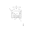
FIG. 4 illustrates a schematic cut-away top view of a portion of a diaphragm and an induction temper system according to embodiments of the invention. - It is noted that the drawings of the invention are not necessarily to scale. The drawings are intended to depict only typical aspects of the invention, and therefore should not be considered as limiting the scope of the invention. In the drawings, like numbering represents like elements between the drawings.
- The subject matter disclosed herein relates to a temper system for a turbine. Specifically, the subject matter disclosed herein relates to a portable induction-based temper system for components of a turbine (e.g., a steam turbine).
- Conventionally, some maintenance of turbine components (e.g., turbine nozzle partitions) involves transport of the components to a maintenance facility. At the maintenance facility, maintenance of static turbine diaphragm nozzle partitions can fall into two categories: minor and major. Minor repairs of static turbine nozzle partitions are conventionally performed using a metal filler applied via a welding process. These minor repairs are typically not stress-relieved after applying the filler, which allows these processes to sometimes be implemented in the field (at a customer site). Major repairs, in contrast, can require stress relief of the diaphragm (including the nozzle partition partitions) through heating in a furnace or an oven. In the case of major repairs, the turbine diaphragm must be transported to and from the maintenance facility for repair. Additionally, major repairs are conventionally performed with the turbine nozzle partitions still disassembled from their associated auxiliary hardware. This requires that the auxiliary hardware (e.g., bolts, supports, keys, sealing strips, etc.) be separated from the nozzle partitions prior to oven tempering. Transport of the turbine, and disassembly of components can be both costly and time consuming.
- In contrast to these conventional approaches, aspects of the invention include a portable induction-based temper system for tempering components of a turbine (e.g., nozzle partitions), on occasion after weld repair of those components. More specifically, aspects of the invention include an induction-based temper system configured to temper nozzle partitions in a turbine (e.g., a steam turbine). This induction-based temper system is compact and portable enough to allow for maintenance of one or more turbine components (e.g., nozzle partition(s)) at remote customer-specific locations. Additionally, this induction-based temper system allows for localized heating of turbine components, which can minimize the impact of tempering on parts of a turbine adjacent or proximate to the component of interest.
- More specifically, in one embodiment, an induction temper system for a turbine is disclosed, the system including: an induction member; a control system operably connected to the induction coil; and a temperature sensor operably connected with the control system, wherein the control system is configured to control an electrical current supplied to the induction member in response to a temperature indicator about a component of the turbine obtained from the temperature sensor.
- Additionally, aspects of the invention provide for a method of localized induction tempering of a turbine component (e.g., a nozzle partition). In one embodiment, the method includes providing an induction coil for applying inductive heat to a turbine nozzle component for the purpose of localized tempering that component. In particular, the method may include providing an induction coil along a radial length of a static diaphragm partition (or, airfoil), and applying inductive heat across the radial length of the static diaphragm partition via the induction coil. This "localized" process can include inductively heating the nozzle partition (raising its temperature from a first, lower temperature to a second, higher temperature), while keeping the nozzle's sidewalls and/or adjacent partitions at a substantially constant first, lower temperature.
- As used herein, and as is known in the art, the terms "temper" and the process of "tempering" involve applying heat to a metal (e.g., steel, iron, etc.) to reduce stress in the metal and increase its toughness and elasticity. As is known in the art, induction heating involves using electromagnetic induction generated by eddy currents surrounding a current carrier to heat a nearby conductive object (e.g., a metal such as steel, iron, etc.). The current carrier (e.g., a wire or electromagnet) carries an alternating current (AC), thereby generating eddy currents around the carrier and within nearby conductors. These nearby conductors have an inherent resistance, and when the eddy currents are passed through these metals, their resistance causes resistive (or, ohmic) heating of that nearby conductor. This heating may be used to temper the nearby conductor (e.g., element of steel, iron, etc.) for the purposes of improving one or more material properties of the conductor, such as making the conductor less brittle.
- Conventional approaches of tempering turbine nozzle partitions do not use the induction-based systems and methods disclosed herein. As the systems disclosed herein are induction-based, it is understood that the localized exposure temperatures of the underlying material (e.g., turbine nozzle partitions) will be higher than in the furnace or oven-based conventional systems. However, in contrast to those over-based conventional systems, aspects of the invention allow for the application of localized heating that does not require removal (or disassembly) of hardware components proximate the nozzle partition. This localized heating may only slightly alter the temperature (e.g., by several degrees Celsius) of adjacent components such as sidewalls or adjacent partitions. Additionally, it is understood that application of induction tempering may be implemented for approximately only 5-15 minute periods per section of material (e.g., nozzle partition). This may be in contrast to the extended tempering periods implemented in conventional systems, which can last as long as 24-36 hours for a whole diaphragm (including ramping up from ambient temperature, hold time at the desired temperature for tempering, and ramp down back to ambient temperature).
- Turning to
FIG. 1 , a schematic plan view of anenvironment 2 including aninduction temper system 4 for tempering a component in a turbine (e.g., one or more turbine nozzle partitions 8) is depicted. Also included in theenvironment 2 is a turbine diaphragm 6 (e.g., a steam turbine diaphragm, partially shown). As is known in the art, thediaphragm 6 can include the plurality of nozzle partitions (or, airfoils) 8. Thenozzle partitions 8 shown are fixed (or, static) nozzle partitions for directing the flow of a working fluid (e.g., steam) across the dynamic turbine blades (not shown) of a conventional turbine rotor (or, rotor) 10. Therotor 10 is shown in phantom inenvironment 2, as therotor 10 may not necessarily accompany thediaphragm 6 in the induction tempering processes described in accordance with aspects of the invention. - During operation of a conventional steam turbine system including the
diaphragm 6 androtor 10, thenozzle partitions 8 can be exposed to steam at extremely high temperatures for extended periods, as well as boiler particle carry-over and solid particle erosion. These temperatures and particle exposure may wear thenozzle partitions 8, causing thosenozzle partitions 8 to erode. In particular, one ormore nozzle partitions 8 can erode proximate its trailing edge, or "finned" portion, diminishing that nozzle partition's 8 ability to direct fluid flow in the turbine. Thesenozzle partitions 8 may require periodic repair as a result. As described herein, conventional repair systems lack both the portability and induction-based functions of theinduction temper system 4 disclosed and described according to embodiments of the invention. Turning more specifically to theinduction temper system 4 ofFIG. 1 , thesystem 4 includes aninduction member 12 and acontrol system 14 operably connected to the induction member 12 (e.g., via hardwired and/or wireless connections). In some embodiments, theinduction member 12 may take the form of an induction coil (e.g., a copper tubing or wire) or an electromagnet at least partially contained in an insulative sleeve. The insulative sleeve can allow for the inductive heating of a proximate metal turbine part (e.g., anozzle partition 8 and/or adjacent weld joint) while preventing electrical arcing between theinduction member 12 and that proximate metal part. In other embodiments, theinduction member 12 may include a metal rod, a "U-shaped" or "J-shaped" member, or any other member (e.g., a copper member) capable of performing the processes described herein. Theinduction member 12 may have an adjustable application length (La), such that it can be applied acrossnozzle partitions 8 and/or weld joints of differing lengths. That is, theinduction member 12 may be pliable such that its application length (La) can be modified to coincide with a length of the part of interest (e.g., a radius Rn of a nozzle partition 8). - Also shown included in the
induction temper system 4 is atemperature sensor 16 operably connected with thecontrol system 14. Thetemperature sensor 16 may be configured to monitor a temperature of theinduction member 12, one or more nozzle partition(s) 8 and/or one or more weld joints or weld accumulations/build-ups proximate to the nozzle partition(s) 8. Thetemperature sensor 16, in some embodiments, may be an infra-red temperature sensor. In some embodiments, theinduction temper system 4 may further include a base member 18 (shown optionally in phantom underlying the control system 14) substantially supporting thecontrol system 14, theinduction member 12 and/or thetemperature sensor 16. Thebase member 18 can take any form capable of physically supporting the weight of thecontrol system 14, theinduction member 12 and/or thetemperatures sensor 16. Thebase member 18 can include a slideable base member, including one or more wheels for rolling around a surface. In some cases, thebase member 18 can include a retractable support structure having one or more retractable member(s) (e.g., a tripod, or 4-legged support structure). In some cases, thebase member 18 can include a retractable support structure allowing for adjustment of the effective height of theinduction temper system 4. Thebase member 18 can include a hydraulically activated, retractable, slideable, and/or rotatable mechanism for moving theinduction temper system 4 within theenvironment 2 or between distinct environments (others not shown). Thebase member 18 may further allow for height adjustment within one ormore environments 2 to allow for theinduction temper system 4 to perform the induction tempering functions described herein on parts at differing relative heights. - The
control system 14 can be configured to control an electrical current supplied to theinduction member 12, based upon a temperature indicator from thetemperature sensor 16. That is, thecontrol system 14 can be configured to monitor the temperature (e.g., via temperature sensor 16) of one or more parts (e.g., anozzle partition 8 and/or adjacent weld joint) and modify an amount of electrical current supplied to theinduction member 12 based upon the determined temperature. It is understood that thecontrol system 14 may continuously monitor the temperature of one or more parts (via temperature sensor 16), or may do so in predetermined periods or intervals. Thecontrol system 14 may be configured to control start-up and cooldown operation of theinduction member 12 according to a predetermined temper cycle. For example, during start-up (or, "ramp-up") operation, thecontrol system 14 can provide a continuously increasing electrical current to theinduction member 12 until theinduction member 12 and/or the member of interest (e.g., thenozzle partition 8 and/or adjacent welds) reach a predetermined desired temperature (as measured by temperature sensor 16). Thecontrol system 14 may then maintain the electrical current supply to theinduction member 12 according to the temper cycle of approximately 5-15 minutes (per nozzle partition 8) to substantially maintain the temperature of theinduction member 12 and/or the member of interest. Thecontrol system 14 may include conventional hardware and/or software components capable of being programmed to follow the prescribed temper cycle. - Also shown as an optional component in the
induction temper system 4 is apower supply system 22 operably connected to the induction member 12 (e.g., via thecontrol system 14 and/or conventional wiring, conduits, etc.). Thepower supply system 22 may be configured to provide electrical current to theinduction member 12, and may include a conventional alternating-current (AC) or direct-current (DC) power supply. Thepower supply system 22 may be configured to connect to a conventional power outlet and/or one ore more conventional battery power systems. In some cases, where the power supply system is a DC power supply, a conventional DC/AC converter may be employed to provide theinductive member 12 with its operational capabilities as described herein. - Additionally, the
induction temper system 4 may include acooling system 24, which can be configured to cool one or more elements in theinduction temper system 4, thereby regulating the temperature of such elements. For example, thecooling system 24 can be configured to circulate a cooling fluid (e.g., water or air) for transferring heat from thepower supply 22 and/orinduction member 12, both of which may generate heat through operation of theinduction temper system 4. Additionally, thecooling system 24 can circulate fluid throughout thecontrol system 14 to cool components thereof. It is further understood that thecooling system 24 may employ fans, conduits and/or other conventional cooling mechanisms for regulating the temperature of components within theinduction temper system 4. - Turning to
FIGS. 2-3 , schematic depictions ofsystems FIGS. 1-3 may represent substantially similar components. As shown,systems similar control systems 14,induction members 12 andtemperature sensors 16, and may differ in the type of base member (e.g., 18A, 18B) shown supporting these similarly labeled components.FIG. 2 illustrates a slideable, or rollingbase member 18A, having a housing 28 (e.g., a cart) at least partially supporting thepower supply 22 and/or the cooling system 24 (both shown in phantom as optionally supported by housing 28).FIG. 3 illustrates abase member 18B having a plurality ofretractable legs 32, which may fold up to form a substantially unitary bundle, and which may each individually retract to vary the effective height (h) of thesystem 36. The effective height (h) may be measured as the distance from theinduction member 12 to a surface (e.g., a floor of a work space). It is understood that the effective height (h) can be modified both by the position of thebase member 18B (e.g., via modification of the position of retractable legs 32) and by the position of theinduction member 12, which in some embodiments, may be bent or otherwise manipulated to modify its overall length as well as its application length (La). In either case (system 26 or system 36), the transportable nature of thebase members induction member 12 such that it can provide localized heating to one or more portions of the diaphragm 6 (e.g., one or more nozzle partitions 8). Combined with the adjustable application length (La) of theinduction member 12, the transportable nature of thebase members -
FIG. 4 illustrates a schematic cut-away top view of a portion of thediaphragm 6 ofFIGS. 1-3 , including anozzle partition 8, according to embodiments of the invention. This view further illustrates a cut-away section of aninduction member 12 overlying a section of thediaphragm 6 according to embodiments of the invention. As shown, theinduction member 12 may be configured to inductively heat thenozzle partition 8 and aweld repair section 44. In some cases, theweld repair section 44 can be located proximate the trailing or "finned" portion of the nozzle partition. Theweld repair section 44 may include a weld build-up or accumulation on the surface of thenozzle partition 8, or may include a welded joint between sections of adjacent nozzles 8 (only one nozzle shown). As illustrated inFIG. 4 , in some embodiments, theinduction member 12 may be configured (e.g., molded, manipulated, placed, held, etc.) to have an application length (La) at least as wide as a radial height (Rn) of thenozzle partition 8, and in some cases, may overlapadjacent sidewalls 46. - In any case, as described herein, aspects of the invention provide for a portable system configured to treat nozzle partitions of a steam turbine diaphragm via induction tempering. This system may be configured to adjust the application length of its induction member to fit differently sized portions of interest (e.g., differently sized nozzle partitions and/or weld build-ups and joints). This induction-based temper system is lighter and significantly more portable than conventional temper systems, while still allowing for reductions in stress and increases in toughness and elasticity of the material of interest.
- It is understood that in alternative embodiments, the induction tempering system disclosed herein can be used in tempering components in a conventional turbine nozzle box (as opposed to a diaphragm as shown and described herein). In this case, the induction tempering system can apply localized inductive heating to components within the nozzle box, including the inlet nozzles, while minimizing heating of surrounding components such as bridge rings.
- The terminology used herein is for the purpose of describing particular embodiments only and is not intended to be limiting of the disclosure. As used herein, the singular forms "a", "an" and "the" are intended to include the plural forms as well, unless the context clearly indicates otherwise. It will be further understood that the terms "comprises" and/or "comprising," when used in this specification, specify the presence of stated features, integers, steps, operations, elements, and/or components, but do not preclude the presence or addition of one or more other features, integers, steps, operations, elements, components, and/or groups thereof.
- This written description uses examples to disclose the invention, including the best mode, and also to enable any person skilled in the art to practice the invention, including making and using any devices or systems and performing any incorporated methods. The patentable scope of the invention is defined by the claims, and may include other examples that occur to those skilled in the art. Such other examples are intended to be within the scope of the claims if they have structural elements that do not differ from the literal language of the claims, or if they include equivalent structural elements with insubstantial differences from the literal languages of the claims.
Claims (14)
- An induction temper system (4) for a turbine, the system comprising:an induction member (12);a control system (14) operably connected to the induction member; anda temperature sensor (16) operably connected with the control system,wherein the control system (14) is configured to control an electrical current supplied to the induction member (12) in response to a temperature indicator about a component of the turbine obtained from the temperature sensor (16).
- The induction temper system of claim 1, further comprising a base member (18) for supporting at least one of the induction member, the control system or the temperature sensor.
- The induction temper system of claim 2, the base member (18) including at least one wheel for movement along a surface.
- The induction temper system of claim 2 or claim 3, the base member (18) including a retractable support member for interacting with a surface.
- The induction temper system of any preceding claim, wherein the control system (14) is configured to control the electrical current supplied to the induction member according to a prescribed temper cycle.
- The induction temper system of any preceding claim, wherein the induction member (12) has an adjustable length.
- The induction temper system of any preceding claim, wherein the temperature sensor (16) is an infrared temperature sensor.
- The induction temper system of any preceding claim, wherein the induction member (12) includes an induction coil.
- The induction temper system of claim 8, wherein the induction coil includes an insulative sleeve and a conductive member substantially contained within the insulative sleeve.
- The induction temper system of any preceding claim, further comprising a power supply (22) system operably connected to the induction member, the power supply system for providing electrical current to the induction member.
- The induction temper system of claim 10, further comprising a cooling system (24) for cooling at least one of the power supply system or the inductive member.
- The induction temper system of any preceding claim, wherein the component of the turbine is a nozzle partition (8) of a steam turbine diaphragm (6), and wherein the induction member (12) is configured to inductively heat the nozzle partition (8) across a radial length of the nozzle partition.
- The induction temper system of any preceding claim, the system for a steam turbine and comprising:an induction member (12);a control system (14) operably connected to the induction member;a temperature sensor (16) operably connected with the control system; anda base member (18) substantially supporting at least one of the control system, the induction member or the temperature sensor,wherein the control system (14) is configured to control an electrical current supplied to the induction member (12) in response to a temperature indicator about a component of the steam turbine obtained from the temperature sensor (16).
- The induction temper system of any preceding claim, the system for a steam turbine nozzle partition and comprising:an induction coil (12);a control system (14) operably connected to the induction coil;a temperature sensor (16) operably connected with the control system; anda base member (18) substantially supporting at least one of the control system, the induction member or the temperature sensor,wherein the control system (14) is configured to control an electrical current supplied to the induction coil (12) in response to a temperature indicator obtained from the temperature sensor (16), andwherein the induction coil (12) is configured to perform a localized heating of the steam turbine nozzle partition across a radial length of the nozzle partition.
Applications Claiming Priority (1)
| Application Number | Priority Date | Filing Date | Title |
|---|---|---|---|
| PL397937A PL397937A1 (en) | 2012-01-30 | 2012-01-30 | Induction annealing system for turbine |
Publications (2)
| Publication Number | Publication Date |
|---|---|
| EP2620512A1 true EP2620512A1 (en) | 2013-07-31 |
| EP2620512B1 EP2620512B1 (en) | 2021-11-10 |
Family
ID=47631347
Family Applications (1)
| Application Number | Title | Priority Date | Filing Date |
|---|---|---|---|
| EP13153268.1A Active EP2620512B1 (en) | 2012-01-30 | 2013-01-30 | Turbine induction temper system |
Country Status (3)
| Country | Link |
|---|---|
| US (1) | US9938596B2 (en) |
| EP (1) | EP2620512B1 (en) |
| PL (1) | PL397937A1 (en) |
Cited By (8)
| Publication number | Priority date | Publication date | Assignee | Title |
|---|---|---|---|---|
| WO2014070403A1 (en) * | 2012-10-29 | 2014-05-08 | General Electric Company | Local heat treatment and thermal management system for engine components |
| WO2015175067A1 (en) * | 2014-05-16 | 2015-11-19 | Illinois Tool Works Inc. | Induction heating system temperature sensor assembly |
| WO2015175071A1 (en) * | 2014-05-16 | 2015-11-19 | Illinois Tool Works Inc. | Induction heating stand assembly |
| US9913320B2 (en) | 2014-05-16 | 2018-03-06 | Illinois Tool Works Inc. | Induction heating system travel sensor assembly |
| US10462853B2 (en) | 2013-05-28 | 2019-10-29 | Illinois Tool Works Inc. | Induction pre-heating and butt welding device for adjacent edges of at least one element to be welded |
| US10638554B2 (en) | 2014-12-23 | 2020-04-28 | Illinois Tool Works Inc. | Systems and methods for interchangeable induction heating systems |
| US11197350B2 (en) | 2014-05-16 | 2021-12-07 | Illinois Tool Works Inc. | Induction heating system connection box |
| US11510290B2 (en) | 2014-05-16 | 2022-11-22 | Illinois Tool Works Inc. | Induction heating system |
Citations (6)
| Publication number | Priority date | Publication date | Assignee | Title |
|---|---|---|---|---|
| US3596037A (en) * | 1967-04-29 | 1971-07-27 | Aeg Elotherm Gmbh | Apparatus for inductively heat-treating steel workpieces |
| EP0106421A1 (en) * | 1982-09-09 | 1984-04-25 | Park-Ohio Industries, Inc. | Method and apparatus for uniform induction heating of an elongated workpiece |
| EP0934795A2 (en) * | 1998-02-03 | 1999-08-11 | United Technologies Corporation | In-situ repair method for a turbomachinery component |
| GB2456628A (en) * | 2008-01-19 | 2009-07-22 | Mtu Aero Engines Gmbh | Apparatus and method for the heat treatment of integral rotors of gas turbines |
| US20100037459A1 (en) * | 2008-08-15 | 2010-02-18 | Leading Edge Turbine Technologies, Ltd. | Method for Correcting Downstream Deflection in Gas Turbine Nozzles |
| EP2267278A2 (en) * | 2009-06-25 | 2010-12-29 | Hitachi, Ltd. | Turbine rotor blade with hardened region |
Family Cites Families (22)
| Publication number | Priority date | Publication date | Assignee | Title |
|---|---|---|---|---|
| US3741821A (en) | 1971-05-10 | 1973-06-26 | United Aircraft Corp | Processing for integral gas turbine disc/blade component |
| GB1522955A (en) * | 1974-12-03 | 1978-08-31 | Rolls Royce | Induction heating apparatus |
| US4437213A (en) | 1982-08-19 | 1984-03-20 | Transamerica Delaval Inc. | Means for tenon-forming a shroud to a turbine rotor |
| PL146997B1 (en) | 1985-07-15 | 1989-04-29 | Induction heater for heating long blocks | |
| DE3535761C1 (en) | 1985-10-07 | 1987-03-26 | Messerschmitt Boelkow Blohm | Riveting machine |
| FR2646114B1 (en) | 1989-04-21 | 1994-04-08 | Gec Alsthom Sa | METHOD AND DEVICE FOR RIVETING A BANDAGE WITH FINS MOUNTS ON A ROTOR |
| US5055648A (en) * | 1989-12-27 | 1991-10-08 | Rockwell International Corporation | Apparatus and method for mechanical properties testing |
| US5736714A (en) * | 1992-11-24 | 1998-04-07 | Bechtold, Jr.; Joseph A. | Portable towel heating appliance with accessories |
| US6084224A (en) * | 1997-03-03 | 2000-07-04 | Chrysler Corporation | In-situ closed loop temperature control for induction tempering |
| GB9720519D0 (en) * | 1997-09-27 | 1997-11-26 | Coflexip Stena Offshore Ltd | Improved induction heating apparatus and method for pipeline welding operations |
| JP2999760B2 (en) | 1998-02-05 | 2000-01-17 | 日本碍子株式会社 | Method for producing beryllium-copper alloy HIP joint and HIP joint |
| DE10102991C2 (en) * | 2000-02-19 | 2003-11-20 | Ald Vacuum Techn Ag | Device for heating a metal workpiece |
| US6526657B2 (en) | 2001-05-07 | 2003-03-04 | General Electric Company | Methods for automated peening of tenons connecting turbine buckets and cover plates |
| US6555801B1 (en) * | 2002-01-23 | 2003-04-29 | Melrose, Inc. | Induction heating coil, device and method of use |
| JP2004027261A (en) | 2002-06-24 | 2004-01-29 | Mitsubishi Heavy Ind Ltd | Local hardening method |
| US6811375B2 (en) * | 2002-10-31 | 2004-11-02 | General Electric Company | Raised sealing surface platform with external breech ring locking system for a brush seal in a turbine and methods of installation |
| US6875966B1 (en) * | 2004-03-15 | 2005-04-05 | Nexicor Llc | Portable induction heating tool for soldering pipes |
| US7389662B2 (en) | 2005-09-30 | 2008-06-24 | General Electric Company | Method and apparatus for self indexing portable automated tenon peening |
| JP4933161B2 (en) * | 2006-06-08 | 2012-05-16 | キヤノン株式会社 | Image heating device |
| US7641739B2 (en) * | 2006-06-13 | 2010-01-05 | The Boeing Company | Friction stir welding tool cleaning method |
| CN104762448B (en) * | 2009-07-30 | 2017-09-01 | 高周波热练株式会社 | Induction hardening equipment, induction hardening method, load coil, annealing device and heat treatment method |
| US7966856B1 (en) | 2009-12-15 | 2011-06-28 | General Electric Company | Robotic peening apparatus |
-
2012
- 2012-01-30 PL PL397937A patent/PL397937A1/en unknown
- 2012-04-24 US US13/454,859 patent/US9938596B2/en active Active
-
2013
- 2013-01-30 EP EP13153268.1A patent/EP2620512B1/en active Active
Patent Citations (6)
| Publication number | Priority date | Publication date | Assignee | Title |
|---|---|---|---|---|
| US3596037A (en) * | 1967-04-29 | 1971-07-27 | Aeg Elotherm Gmbh | Apparatus for inductively heat-treating steel workpieces |
| EP0106421A1 (en) * | 1982-09-09 | 1984-04-25 | Park-Ohio Industries, Inc. | Method and apparatus for uniform induction heating of an elongated workpiece |
| EP0934795A2 (en) * | 1998-02-03 | 1999-08-11 | United Technologies Corporation | In-situ repair method for a turbomachinery component |
| GB2456628A (en) * | 2008-01-19 | 2009-07-22 | Mtu Aero Engines Gmbh | Apparatus and method for the heat treatment of integral rotors of gas turbines |
| US20100037459A1 (en) * | 2008-08-15 | 2010-02-18 | Leading Edge Turbine Technologies, Ltd. | Method for Correcting Downstream Deflection in Gas Turbine Nozzles |
| EP2267278A2 (en) * | 2009-06-25 | 2010-12-29 | Hitachi, Ltd. | Turbine rotor blade with hardened region |
Cited By (14)
| Publication number | Priority date | Publication date | Assignee | Title |
|---|---|---|---|---|
| WO2014070403A1 (en) * | 2012-10-29 | 2014-05-08 | General Electric Company | Local heat treatment and thermal management system for engine components |
| US10462853B2 (en) | 2013-05-28 | 2019-10-29 | Illinois Tool Works Inc. | Induction pre-heating and butt welding device for adjacent edges of at least one element to be welded |
| CN106536764B (en) * | 2014-05-16 | 2019-06-07 | 伊利诺斯工具制品有限公司 | Induction heating system temperature sensor assembly |
| CN106538048A (en) * | 2014-05-16 | 2017-03-22 | 伊利诺斯工具制品有限公司 | Induction heating stand assembly |
| CN106536764A (en) * | 2014-05-16 | 2017-03-22 | 伊利诺斯工具制品有限公司 | Induction heating system temperature sensor assembly |
| US9913320B2 (en) | 2014-05-16 | 2018-03-06 | Illinois Tool Works Inc. | Induction heating system travel sensor assembly |
| WO2015175071A1 (en) * | 2014-05-16 | 2015-11-19 | Illinois Tool Works Inc. | Induction heating stand assembly |
| WO2015175067A1 (en) * | 2014-05-16 | 2015-11-19 | Illinois Tool Works Inc. | Induction heating system temperature sensor assembly |
| CN106538048B (en) * | 2014-05-16 | 2019-11-12 | 伊利诺斯工具制品有限公司 | Induction heating stand assembly |
| US10863591B2 (en) | 2014-05-16 | 2020-12-08 | Illinois Tool Works Inc. | Induction heating stand assembly |
| US11076454B2 (en) | 2014-05-16 | 2021-07-27 | Illinois Tool Works Inc. | Induction heating system temperature sensor assembly |
| US11197350B2 (en) | 2014-05-16 | 2021-12-07 | Illinois Tool Works Inc. | Induction heating system connection box |
| US11510290B2 (en) | 2014-05-16 | 2022-11-22 | Illinois Tool Works Inc. | Induction heating system |
| US10638554B2 (en) | 2014-12-23 | 2020-04-28 | Illinois Tool Works Inc. | Systems and methods for interchangeable induction heating systems |
Also Published As
| Publication number | Publication date |
|---|---|
| US20130193134A1 (en) | 2013-08-01 |
| US9938596B2 (en) | 2018-04-10 |
| PL397937A1 (en) | 2013-08-05 |
| EP2620512B1 (en) | 2021-11-10 |
Similar Documents
| Publication | Publication Date | Title |
|---|---|---|
| US9938596B2 (en) | Turbine induction temper system | |
| US11729868B2 (en) | Induction heating device, induction heating equipment, induction heating method, and heat treatment method | |
| RU2709494C1 (en) | Compact homogenization line by continuous annealing | |
| JPH0340203B2 (en) | ||
| US20070158321A1 (en) | Apparatus and Method for Performing Welding at Elevated Temperature | |
| US10731849B2 (en) | Apparatus and method for welding a waterwall panel | |
| CN103068516A (en) | Method for manufacturing components by selective laser melting | |
| CN105705263A (en) | Large scale metal forming | |
| US20170259384A1 (en) | System and method for robotic thermal treatment by heat induction | |
| US10834788B2 (en) | Induction heating device | |
| EP2999310B1 (en) | System and method for repairing blades | |
| CN114340840A (en) | System and method for manufacturing a component | |
| JP2012219311A (en) | Induction heating apparatus and induction heating method | |
| US20180114307A1 (en) | System and method for detecting anomalies in a component | |
| EP3477066A1 (en) | Installation apparatus for a load-coupling of a turbine system and method of installing a load-coupling in a turbine system | |
| JP2019157166A (en) | Work tempering process, and machine part obtained by said process | |
| RU2617077C2 (en) | Method of laser powder protective coating overlaying on the inlet edgs of steam turbines working blades | |
| CN107634616A (en) | A kind of process and device of rotor guard ring of turbine generator hot jacket | |
| CN205754923U (en) | A kind of efficient box quenched induction apparatus | |
| RU231570U1 (en) | Installation for softening the surface layer of the metal of the rolling surface of a wheel pair with adjustable geometry of the inductor | |
| CN112176175A (en) | TP347 thick-wall pipeline stabilizing heat treatment method | |
| CN119609578B (en) | On-site welding manufacturing method for the transition section and elbow of a steam turbine intermediate pressure cylinder | |
| RU2263419C1 (en) | Freight car foot heater | |
| JP2004202509A (en) | On-site welding repair method for hydraulic equipment | |
| CN108265162A (en) | Local heat treatment device used after laser repair of shaft parts and temperature control method |
Legal Events
| Date | Code | Title | Description |
|---|---|---|---|
| PUAI | Public reference made under article 153(3) epc to a published international application that has entered the european phase |
Free format text: ORIGINAL CODE: 0009012 |
|
| AK | Designated contracting states |
Kind code of ref document: A1 Designated state(s): AL AT BE BG CH CY CZ DE DK EE ES FI FR GB GR HR HU IE IS IT LI LT LU LV MC MK MT NL NO PL PT RO RS SE SI SK SM TR |
|
| AX | Request for extension of the european patent |
Extension state: BA ME |
|
| 17P | Request for examination filed |
Effective date: 20140131 |
|
| RBV | Designated contracting states (corrected) |
Designated state(s): AL AT BE BG CH CY CZ DE DK EE ES FI FR GB GR HR HU IE IS IT LI LT LU LV MC MK MT NL NO PL PT RO RS SE SI SK SM TR |
|
| STAA | Information on the status of an ep patent application or granted ep patent |
Free format text: STATUS: EXAMINATION IS IN PROGRESS |
|
| 17Q | First examination report despatched |
Effective date: 20171025 |
|
| GRAP | Despatch of communication of intention to grant a patent |
Free format text: ORIGINAL CODE: EPIDOSNIGR1 |
|
| STAA | Information on the status of an ep patent application or granted ep patent |
Free format text: STATUS: GRANT OF PATENT IS INTENDED |
|
| INTG | Intention to grant announced |
Effective date: 20210618 |
|
| GRAS | Grant fee paid |
Free format text: ORIGINAL CODE: EPIDOSNIGR3 |
|
| GRAA | (expected) grant |
Free format text: ORIGINAL CODE: 0009210 |
|
| STAA | Information on the status of an ep patent application or granted ep patent |
Free format text: STATUS: THE PATENT HAS BEEN GRANTED |
|
| AK | Designated contracting states |
Kind code of ref document: B1 Designated state(s): AL AT BE BG CH CY CZ DE DK EE ES FI FR GB GR HR HU IE IS IT LI LT LU LV MC MK MT NL NO PL PT RO RS SE SI SK SM TR |
|
| REG | Reference to a national code |
Ref country code: GB Ref legal event code: FG4D |
|
| REG | Reference to a national code |
Ref country code: AT Ref legal event code: REF Ref document number: 1446149 Country of ref document: AT Kind code of ref document: T Effective date: 20211115 Ref country code: CH Ref legal event code: EP |
|
| REG | Reference to a national code |
Ref country code: DE Ref legal event code: R096 Ref document number: 602013079959 Country of ref document: DE |
|
| REG | Reference to a national code |
Ref country code: IE Ref legal event code: FG4D |
|
| REG | Reference to a national code |
Ref country code: NL Ref legal event code: FP |
|
| REG | Reference to a national code |
Ref country code: LT Ref legal event code: MG9D |
|
| REG | Reference to a national code |
Ref country code: AT Ref legal event code: MK05 Ref document number: 1446149 Country of ref document: AT Kind code of ref document: T Effective date: 20211110 |
|
| PG25 | Lapsed in a contracting state [announced via postgrant information from national office to epo] |
Ref country code: RS Free format text: LAPSE BECAUSE OF FAILURE TO SUBMIT A TRANSLATION OF THE DESCRIPTION OR TO PAY THE FEE WITHIN THE PRESCRIBED TIME-LIMIT Effective date: 20211110 Ref country code: LT Free format text: LAPSE BECAUSE OF FAILURE TO SUBMIT A TRANSLATION OF THE DESCRIPTION OR TO PAY THE FEE WITHIN THE PRESCRIBED TIME-LIMIT Effective date: 20211110 Ref country code: FI Free format text: LAPSE BECAUSE OF FAILURE TO SUBMIT A TRANSLATION OF THE DESCRIPTION OR TO PAY THE FEE WITHIN THE PRESCRIBED TIME-LIMIT Effective date: 20211110 Ref country code: BG Free format text: LAPSE BECAUSE OF FAILURE TO SUBMIT A TRANSLATION OF THE DESCRIPTION OR TO PAY THE FEE WITHIN THE PRESCRIBED TIME-LIMIT Effective date: 20220210 Ref country code: AT Free format text: LAPSE BECAUSE OF FAILURE TO SUBMIT A TRANSLATION OF THE DESCRIPTION OR TO PAY THE FEE WITHIN THE PRESCRIBED TIME-LIMIT Effective date: 20211110 |
|
| PG25 | Lapsed in a contracting state [announced via postgrant information from national office to epo] |
Ref country code: IS Free format text: LAPSE BECAUSE OF FAILURE TO SUBMIT A TRANSLATION OF THE DESCRIPTION OR TO PAY THE FEE WITHIN THE PRESCRIBED TIME-LIMIT Effective date: 20220310 Ref country code: SE Free format text: LAPSE BECAUSE OF FAILURE TO SUBMIT A TRANSLATION OF THE DESCRIPTION OR TO PAY THE FEE WITHIN THE PRESCRIBED TIME-LIMIT Effective date: 20211110 Ref country code: PT Free format text: LAPSE BECAUSE OF FAILURE TO SUBMIT A TRANSLATION OF THE DESCRIPTION OR TO PAY THE FEE WITHIN THE PRESCRIBED TIME-LIMIT Effective date: 20220310 Ref country code: PL Free format text: LAPSE BECAUSE OF FAILURE TO SUBMIT A TRANSLATION OF THE DESCRIPTION OR TO PAY THE FEE WITHIN THE PRESCRIBED TIME-LIMIT Effective date: 20211110 Ref country code: NO Free format text: LAPSE BECAUSE OF FAILURE TO SUBMIT A TRANSLATION OF THE DESCRIPTION OR TO PAY THE FEE WITHIN THE PRESCRIBED TIME-LIMIT Effective date: 20220210 Ref country code: LV Free format text: LAPSE BECAUSE OF FAILURE TO SUBMIT A TRANSLATION OF THE DESCRIPTION OR TO PAY THE FEE WITHIN THE PRESCRIBED TIME-LIMIT Effective date: 20211110 Ref country code: HR Free format text: LAPSE BECAUSE OF FAILURE TO SUBMIT A TRANSLATION OF THE DESCRIPTION OR TO PAY THE FEE WITHIN THE PRESCRIBED TIME-LIMIT Effective date: 20211110 Ref country code: GR Free format text: LAPSE BECAUSE OF FAILURE TO SUBMIT A TRANSLATION OF THE DESCRIPTION OR TO PAY THE FEE WITHIN THE PRESCRIBED TIME-LIMIT Effective date: 20220211 Ref country code: ES Free format text: LAPSE BECAUSE OF FAILURE TO SUBMIT A TRANSLATION OF THE DESCRIPTION OR TO PAY THE FEE WITHIN THE PRESCRIBED TIME-LIMIT Effective date: 20211110 |
|
| PG25 | Lapsed in a contracting state [announced via postgrant information from national office to epo] |
Ref country code: SM Free format text: LAPSE BECAUSE OF FAILURE TO SUBMIT A TRANSLATION OF THE DESCRIPTION OR TO PAY THE FEE WITHIN THE PRESCRIBED TIME-LIMIT Effective date: 20211110 Ref country code: SK Free format text: LAPSE BECAUSE OF FAILURE TO SUBMIT A TRANSLATION OF THE DESCRIPTION OR TO PAY THE FEE WITHIN THE PRESCRIBED TIME-LIMIT Effective date: 20211110 Ref country code: RO Free format text: LAPSE BECAUSE OF FAILURE TO SUBMIT A TRANSLATION OF THE DESCRIPTION OR TO PAY THE FEE WITHIN THE PRESCRIBED TIME-LIMIT Effective date: 20211110 Ref country code: EE Free format text: LAPSE BECAUSE OF FAILURE TO SUBMIT A TRANSLATION OF THE DESCRIPTION OR TO PAY THE FEE WITHIN THE PRESCRIBED TIME-LIMIT Effective date: 20211110 Ref country code: DK Free format text: LAPSE BECAUSE OF FAILURE TO SUBMIT A TRANSLATION OF THE DESCRIPTION OR TO PAY THE FEE WITHIN THE PRESCRIBED TIME-LIMIT Effective date: 20211110 Ref country code: CZ Free format text: LAPSE BECAUSE OF FAILURE TO SUBMIT A TRANSLATION OF THE DESCRIPTION OR TO PAY THE FEE WITHIN THE PRESCRIBED TIME-LIMIT Effective date: 20211110 |
|
| REG | Reference to a national code |
Ref country code: DE Ref legal event code: R097 Ref document number: 602013079959 Country of ref document: DE |
|
| PG25 | Lapsed in a contracting state [announced via postgrant information from national office to epo] |
Ref country code: MC Free format text: LAPSE BECAUSE OF FAILURE TO SUBMIT A TRANSLATION OF THE DESCRIPTION OR TO PAY THE FEE WITHIN THE PRESCRIBED TIME-LIMIT Effective date: 20211110 |
|
| REG | Reference to a national code |
Ref country code: CH Ref legal event code: PL |
|
| PLBE | No opposition filed within time limit |
Free format text: ORIGINAL CODE: 0009261 |
|
| STAA | Information on the status of an ep patent application or granted ep patent |
Free format text: STATUS: NO OPPOSITION FILED WITHIN TIME LIMIT |
|
| REG | Reference to a national code |
Ref country code: BE Ref legal event code: MM Effective date: 20220131 |
|
| 26N | No opposition filed |
Effective date: 20220811 |
|
| PG25 | Lapsed in a contracting state [announced via postgrant information from national office to epo] |
Ref country code: LU Free format text: LAPSE BECAUSE OF NON-PAYMENT OF DUE FEES Effective date: 20220130 Ref country code: AL Free format text: LAPSE BECAUSE OF FAILURE TO SUBMIT A TRANSLATION OF THE DESCRIPTION OR TO PAY THE FEE WITHIN THE PRESCRIBED TIME-LIMIT Effective date: 20211110 |
|
| PG25 | Lapsed in a contracting state [announced via postgrant information from national office to epo] |
Ref country code: SI Free format text: LAPSE BECAUSE OF FAILURE TO SUBMIT A TRANSLATION OF THE DESCRIPTION OR TO PAY THE FEE WITHIN THE PRESCRIBED TIME-LIMIT Effective date: 20211110 Ref country code: FR Free format text: LAPSE BECAUSE OF NON-PAYMENT OF DUE FEES Effective date: 20220131 Ref country code: BE Free format text: LAPSE BECAUSE OF NON-PAYMENT OF DUE FEES Effective date: 20220131 |
|
| PG25 | Lapsed in a contracting state [announced via postgrant information from national office to epo] |
Ref country code: LI Free format text: LAPSE BECAUSE OF NON-PAYMENT OF DUE FEES Effective date: 20220131 Ref country code: CH Free format text: LAPSE BECAUSE OF NON-PAYMENT OF DUE FEES Effective date: 20220131 |
|
| PG25 | Lapsed in a contracting state [announced via postgrant information from national office to epo] |
Ref country code: IE Free format text: LAPSE BECAUSE OF NON-PAYMENT OF DUE FEES Effective date: 20220130 |
|
| REG | Reference to a national code |
Ref country code: DE Ref legal event code: R082 Ref document number: 602013079959 Country of ref document: DE Ref country code: DE Ref legal event code: R081 Ref document number: 602013079959 Country of ref document: DE Owner name: GENERAL ELECTRIC TECHNOLOGY GMBH, CH Free format text: FORMER OWNER: GENERAL ELECTRIC COMPANY, SCHENECTADY, NY, US |
|
| REG | Reference to a national code |
Ref country code: GB Ref legal event code: 732E Free format text: REGISTERED BETWEEN 20240222 AND 20240228 |
|
| PG25 | Lapsed in a contracting state [announced via postgrant information from national office to epo] |
Ref country code: HU Free format text: LAPSE BECAUSE OF FAILURE TO SUBMIT A TRANSLATION OF THE DESCRIPTION OR TO PAY THE FEE WITHIN THE PRESCRIBED TIME-LIMIT; INVALID AB INITIO Effective date: 20130130 |
|
| REG | Reference to a national code |
Ref country code: NL Ref legal event code: PD Owner name: GENERAL ELECTRIC TECHNOLOGY GMBH; CH Free format text: DETAILS ASSIGNMENT: CHANGE OF OWNER(S), ASSIGNMENT; FORMER OWNER NAME: GENERAL ELECTRIC COMPANY Effective date: 20240410 |
|
| PG25 | Lapsed in a contracting state [announced via postgrant information from national office to epo] |
Ref country code: MK Free format text: LAPSE BECAUSE OF FAILURE TO SUBMIT A TRANSLATION OF THE DESCRIPTION OR TO PAY THE FEE WITHIN THE PRESCRIBED TIME-LIMIT Effective date: 20211110 Ref country code: CY Free format text: LAPSE BECAUSE OF FAILURE TO SUBMIT A TRANSLATION OF THE DESCRIPTION OR TO PAY THE FEE WITHIN THE PRESCRIBED TIME-LIMIT Effective date: 20211110 |
|
| PG25 | Lapsed in a contracting state [announced via postgrant information from national office to epo] |
Ref country code: MT Free format text: LAPSE BECAUSE OF FAILURE TO SUBMIT A TRANSLATION OF THE DESCRIPTION OR TO PAY THE FEE WITHIN THE PRESCRIBED TIME-LIMIT Effective date: 20211110 |
|
| PG25 | Lapsed in a contracting state [announced via postgrant information from national office to epo] |
Ref country code: TR Free format text: LAPSE BECAUSE OF FAILURE TO SUBMIT A TRANSLATION OF THE DESCRIPTION OR TO PAY THE FEE WITHIN THE PRESCRIBED TIME-LIMIT Effective date: 20211110 |
|
| PGFP | Annual fee paid to national office [announced via postgrant information from national office to epo] |
Ref country code: GB Payment date: 20251219 Year of fee payment: 14 |
|
| PGFP | Annual fee paid to national office [announced via postgrant information from national office to epo] |
Ref country code: NL Payment date: 20251217 Year of fee payment: 14 |
|
| PGFP | Annual fee paid to national office [announced via postgrant information from national office to epo] |
Ref country code: DE Payment date: 20251217 Year of fee payment: 14 |
|
| PGFP | Annual fee paid to national office [announced via postgrant information from national office to epo] |
Ref country code: IT Payment date: 20260107 Year of fee payment: 14 |