EP2620240B1 - Hollow airfoil construction utilizing functionally graded materials - Google Patents
Hollow airfoil construction utilizing functionally graded materials Download PDFInfo
- Publication number
- EP2620240B1 EP2620240B1 EP13151444.0A EP13151444A EP2620240B1 EP 2620240 B1 EP2620240 B1 EP 2620240B1 EP 13151444 A EP13151444 A EP 13151444A EP 2620240 B1 EP2620240 B1 EP 2620240B1
- Authority
- EP
- European Patent Office
- Prior art keywords
- airfoil
- layer
- set forth
- layers
- deposition
- Prior art date
- Legal status (The legal status is an assumption and is not a legal conclusion. Google has not performed a legal analysis and makes no representation as to the accuracy of the status listed.)
- Revoked
Links
Images



Classifications
-
- B—PERFORMING OPERATIONS; TRANSPORTING
- B22—CASTING; POWDER METALLURGY
- B22F—WORKING METALLIC POWDER; MANUFACTURE OF ARTICLES FROM METALLIC POWDER; MAKING METALLIC POWDER; APPARATUS OR DEVICES SPECIALLY ADAPTED FOR METALLIC POWDER
- B22F5/00—Manufacture of workpieces or articles from metallic powder characterised by the special shape of the product
- B22F5/04—Manufacture of workpieces or articles from metallic powder characterised by the special shape of the product of turbine blades
-
- B—PERFORMING OPERATIONS; TRANSPORTING
- B21—MECHANICAL METAL-WORKING WITHOUT ESSENTIALLY REMOVING MATERIAL; PUNCHING METAL
- B21D—WORKING OR PROCESSING OF SHEET METAL OR METAL TUBES, RODS OR PROFILES WITHOUT ESSENTIALLY REMOVING MATERIAL; PUNCHING METAL
- B21D53/00—Making other particular articles
- B21D53/78—Making other particular articles propeller blades; turbine blades
-
- B—PERFORMING OPERATIONS; TRANSPORTING
- B22—CASTING; POWDER METALLURGY
- B22F—WORKING METALLIC POWDER; MANUFACTURE OF ARTICLES FROM METALLIC POWDER; MAKING METALLIC POWDER; APPARATUS OR DEVICES SPECIALLY ADAPTED FOR METALLIC POWDER
- B22F10/00—Additive manufacturing of workpieces or articles from metallic powder
- B22F10/20—Direct sintering or melting
- B22F10/25—Direct deposition of metal particles, e.g. direct metal deposition [DMD] or laser engineered net shaping [LENS]
-
- B—PERFORMING OPERATIONS; TRANSPORTING
- B22—CASTING; POWDER METALLURGY
- B22F—WORKING METALLIC POWDER; MANUFACTURE OF ARTICLES FROM METALLIC POWDER; MAKING METALLIC POWDER; APPARATUS OR DEVICES SPECIALLY ADAPTED FOR METALLIC POWDER
- B22F10/00—Additive manufacturing of workpieces or articles from metallic powder
- B22F10/30—Process control
- B22F10/38—Process control to achieve specific product aspects, e.g. surface smoothness, density, porosity or hollow structures
-
- B—PERFORMING OPERATIONS; TRANSPORTING
- B22—CASTING; POWDER METALLURGY
- B22F—WORKING METALLIC POWDER; MANUFACTURE OF ARTICLES FROM METALLIC POWDER; MAKING METALLIC POWDER; APPARATUS OR DEVICES SPECIALLY ADAPTED FOR METALLIC POWDER
- B22F10/00—Additive manufacturing of workpieces or articles from metallic powder
- B22F10/50—Treatment of workpieces or articles during build-up, e.g. treatments applied to fused layers during build-up
-
- B—PERFORMING OPERATIONS; TRANSPORTING
- B22—CASTING; POWDER METALLURGY
- B22F—WORKING METALLIC POWDER; MANUFACTURE OF ARTICLES FROM METALLIC POWDER; MAKING METALLIC POWDER; APPARATUS OR DEVICES SPECIALLY ADAPTED FOR METALLIC POWDER
- B22F10/00—Additive manufacturing of workpieces or articles from metallic powder
- B22F10/60—Treatment of workpieces or articles after build-up
- B22F10/66—Treatment of workpieces or articles after build-up by mechanical means
-
- B—PERFORMING OPERATIONS; TRANSPORTING
- B23—MACHINE TOOLS; METAL-WORKING NOT OTHERWISE PROVIDED FOR
- B23P—METAL-WORKING NOT OTHERWISE PROVIDED FOR; COMBINED OPERATIONS; UNIVERSAL MACHINE TOOLS
- B23P15/00—Making specific metal objects by operations not covered by a single other subclass or a group in this subclass
- B23P15/04—Making specific metal objects by operations not covered by a single other subclass or a group in this subclass turbine or like blades from several pieces
-
- B—PERFORMING OPERATIONS; TRANSPORTING
- B29—WORKING OF PLASTICS; WORKING OF SUBSTANCES IN A PLASTIC STATE IN GENERAL
- B29C—SHAPING OR JOINING OF PLASTICS; SHAPING OF MATERIAL IN A PLASTIC STATE, NOT OTHERWISE PROVIDED FOR; AFTER-TREATMENT OF THE SHAPED PRODUCTS, e.g. REPAIRING
- B29C64/00—Additive manufacturing, i.e. manufacturing of three-dimensional [3D] objects by additive deposition, additive agglomeration or additive layering, e.g. by 3D printing, stereolithography or selective laser sintering
- B29C64/10—Processes of additive manufacturing
- B29C64/141—Processes of additive manufacturing using only solid materials
- B29C64/153—Processes of additive manufacturing using only solid materials using layers of powder being selectively joined, e.g. by selective laser sintering or melting
-
- B—PERFORMING OPERATIONS; TRANSPORTING
- B29—WORKING OF PLASTICS; WORKING OF SUBSTANCES IN A PLASTIC STATE IN GENERAL
- B29C—SHAPING OR JOINING OF PLASTICS; SHAPING OF MATERIAL IN A PLASTIC STATE, NOT OTHERWISE PROVIDED FOR; AFTER-TREATMENT OF THE SHAPED PRODUCTS, e.g. REPAIRING
- B29C64/00—Additive manufacturing, i.e. manufacturing of three-dimensional [3D] objects by additive deposition, additive agglomeration or additive layering, e.g. by 3D printing, stereolithography or selective laser sintering
- B29C64/30—Auxiliary operations or equipment
- B29C64/386—Data acquisition or data processing for additive manufacturing
-
- B—PERFORMING OPERATIONS; TRANSPORTING
- B33—ADDITIVE MANUFACTURING TECHNOLOGY
- B33Y—ADDITIVE MANUFACTURING, i.e. MANUFACTURING OF THREE-DIMENSIONAL [3D] OBJECTS BY ADDITIVE DEPOSITION, ADDITIVE AGGLOMERATION OR ADDITIVE LAYERING, e.g. BY 3D PRINTING, STEREOLITHOGRAPHY OR SELECTIVE LASER SINTERING
- B33Y50/00—Data acquisition or data processing for additive manufacturing
- B33Y50/02—Data acquisition or data processing for additive manufacturing for controlling or regulating additive manufacturing processes
-
- C—CHEMISTRY; METALLURGY
- C22—METALLURGY; FERROUS OR NON-FERROUS ALLOYS; TREATMENT OF ALLOYS OR NON-FERROUS METALS
- C22C—ALLOYS
- C22C14/00—Alloys based on titanium
-
- C—CHEMISTRY; METALLURGY
- C23—COATING METALLIC MATERIAL; COATING MATERIAL WITH METALLIC MATERIAL; CHEMICAL SURFACE TREATMENT; DIFFUSION TREATMENT OF METALLIC MATERIAL; COATING BY VACUUM EVAPORATION, BY SPUTTERING, BY ION IMPLANTATION OR BY CHEMICAL VAPOUR DEPOSITION, IN GENERAL; INHIBITING CORROSION OF METALLIC MATERIAL OR INCRUSTATION IN GENERAL
- C23C—COATING METALLIC MATERIAL; COATING MATERIAL WITH METALLIC MATERIAL; SURFACE TREATMENT OF METALLIC MATERIAL BY DIFFUSION INTO THE SURFACE, BY CHEMICAL CONVERSION OR SUBSTITUTION; COATING BY VACUUM EVAPORATION, BY SPUTTERING, BY ION IMPLANTATION OR BY CHEMICAL VAPOUR DEPOSITION, IN GENERAL
- C23C14/00—Coating by vacuum evaporation, by sputtering or by ion implantation of the coating forming material
- C23C14/22—Coating by vacuum evaporation, by sputtering or by ion implantation of the coating forming material characterised by the process of coating
- C23C14/24—Vacuum evaporation
- C23C14/28—Vacuum evaporation by wave energy or particle radiation
-
- C—CHEMISTRY; METALLURGY
- C23—COATING METALLIC MATERIAL; COATING MATERIAL WITH METALLIC MATERIAL; CHEMICAL SURFACE TREATMENT; DIFFUSION TREATMENT OF METALLIC MATERIAL; COATING BY VACUUM EVAPORATION, BY SPUTTERING, BY ION IMPLANTATION OR BY CHEMICAL VAPOUR DEPOSITION, IN GENERAL; INHIBITING CORROSION OF METALLIC MATERIAL OR INCRUSTATION IN GENERAL
- C23C—COATING METALLIC MATERIAL; COATING MATERIAL WITH METALLIC MATERIAL; SURFACE TREATMENT OF METALLIC MATERIAL BY DIFFUSION INTO THE SURFACE, BY CHEMICAL CONVERSION OR SUBSTITUTION; COATING BY VACUUM EVAPORATION, BY SPUTTERING, BY ION IMPLANTATION OR BY CHEMICAL VAPOUR DEPOSITION, IN GENERAL
- C23C22/00—Chemical surface treatment of metallic material by reaction of the surface with a reactive liquid, leaving reaction products of surface material in the coating, e.g. conversion coatings, passivation of metals
- C23C22/70—Chemical surface treatment of metallic material by reaction of the surface with a reactive liquid, leaving reaction products of surface material in the coating, e.g. conversion coatings, passivation of metals using melts
-
- C—CHEMISTRY; METALLURGY
- C23—COATING METALLIC MATERIAL; COATING MATERIAL WITH METALLIC MATERIAL; CHEMICAL SURFACE TREATMENT; DIFFUSION TREATMENT OF METALLIC MATERIAL; COATING BY VACUUM EVAPORATION, BY SPUTTERING, BY ION IMPLANTATION OR BY CHEMICAL VAPOUR DEPOSITION, IN GENERAL; INHIBITING CORROSION OF METALLIC MATERIAL OR INCRUSTATION IN GENERAL
- C23C—COATING METALLIC MATERIAL; COATING MATERIAL WITH METALLIC MATERIAL; SURFACE TREATMENT OF METALLIC MATERIAL BY DIFFUSION INTO THE SURFACE, BY CHEMICAL CONVERSION OR SUBSTITUTION; COATING BY VACUUM EVAPORATION, BY SPUTTERING, BY ION IMPLANTATION OR BY CHEMICAL VAPOUR DEPOSITION, IN GENERAL
- C23C22/00—Chemical surface treatment of metallic material by reaction of the surface with a reactive liquid, leaving reaction products of surface material in the coating, e.g. conversion coatings, passivation of metals
- C23C22/70—Chemical surface treatment of metallic material by reaction of the surface with a reactive liquid, leaving reaction products of surface material in the coating, e.g. conversion coatings, passivation of metals using melts
- C23C22/72—Treatment of iron or alloys based thereon
-
- C—CHEMISTRY; METALLURGY
- C23—COATING METALLIC MATERIAL; COATING MATERIAL WITH METALLIC MATERIAL; CHEMICAL SURFACE TREATMENT; DIFFUSION TREATMENT OF METALLIC MATERIAL; COATING BY VACUUM EVAPORATION, BY SPUTTERING, BY ION IMPLANTATION OR BY CHEMICAL VAPOUR DEPOSITION, IN GENERAL; INHIBITING CORROSION OF METALLIC MATERIAL OR INCRUSTATION IN GENERAL
- C23C—COATING METALLIC MATERIAL; COATING MATERIAL WITH METALLIC MATERIAL; SURFACE TREATMENT OF METALLIC MATERIAL BY DIFFUSION INTO THE SURFACE, BY CHEMICAL CONVERSION OR SUBSTITUTION; COATING BY VACUUM EVAPORATION, BY SPUTTERING, BY ION IMPLANTATION OR BY CHEMICAL VAPOUR DEPOSITION, IN GENERAL
- C23C22/00—Chemical surface treatment of metallic material by reaction of the surface with a reactive liquid, leaving reaction products of surface material in the coating, e.g. conversion coatings, passivation of metals
- C23C22/73—Chemical surface treatment of metallic material by reaction of the surface with a reactive liquid, leaving reaction products of surface material in the coating, e.g. conversion coatings, passivation of metals characterised by the process
-
- C—CHEMISTRY; METALLURGY
- C23—COATING METALLIC MATERIAL; COATING MATERIAL WITH METALLIC MATERIAL; CHEMICAL SURFACE TREATMENT; DIFFUSION TREATMENT OF METALLIC MATERIAL; COATING BY VACUUM EVAPORATION, BY SPUTTERING, BY ION IMPLANTATION OR BY CHEMICAL VAPOUR DEPOSITION, IN GENERAL; INHIBITING CORROSION OF METALLIC MATERIAL OR INCRUSTATION IN GENERAL
- C23C—COATING METALLIC MATERIAL; COATING MATERIAL WITH METALLIC MATERIAL; SURFACE TREATMENT OF METALLIC MATERIAL BY DIFFUSION INTO THE SURFACE, BY CHEMICAL CONVERSION OR SUBSTITUTION; COATING BY VACUUM EVAPORATION, BY SPUTTERING, BY ION IMPLANTATION OR BY CHEMICAL VAPOUR DEPOSITION, IN GENERAL
- C23C24/00—Coating starting from inorganic powder
- C23C24/08—Coating starting from inorganic powder by application of heat or pressure and heat
- C23C24/10—Coating starting from inorganic powder by application of heat or pressure and heat with intermediate formation of a liquid phase in the layer
-
- C—CHEMISTRY; METALLURGY
- C23—COATING METALLIC MATERIAL; COATING MATERIAL WITH METALLIC MATERIAL; CHEMICAL SURFACE TREATMENT; DIFFUSION TREATMENT OF METALLIC MATERIAL; COATING BY VACUUM EVAPORATION, BY SPUTTERING, BY ION IMPLANTATION OR BY CHEMICAL VAPOUR DEPOSITION, IN GENERAL; INHIBITING CORROSION OF METALLIC MATERIAL OR INCRUSTATION IN GENERAL
- C23C—COATING METALLIC MATERIAL; COATING MATERIAL WITH METALLIC MATERIAL; SURFACE TREATMENT OF METALLIC MATERIAL BY DIFFUSION INTO THE SURFACE, BY CHEMICAL CONVERSION OR SUBSTITUTION; COATING BY VACUUM EVAPORATION, BY SPUTTERING, BY ION IMPLANTATION OR BY CHEMICAL VAPOUR DEPOSITION, IN GENERAL
- C23C26/00—Coating not provided for in groups C23C2/00 - C23C24/00
- C23C26/02—Coating not provided for in groups C23C2/00 - C23C24/00 applying molten material to the substrate
-
- C—CHEMISTRY; METALLURGY
- C23—COATING METALLIC MATERIAL; COATING MATERIAL WITH METALLIC MATERIAL; CHEMICAL SURFACE TREATMENT; DIFFUSION TREATMENT OF METALLIC MATERIAL; COATING BY VACUUM EVAPORATION, BY SPUTTERING, BY ION IMPLANTATION OR BY CHEMICAL VAPOUR DEPOSITION, IN GENERAL; INHIBITING CORROSION OF METALLIC MATERIAL OR INCRUSTATION IN GENERAL
- C23C—COATING METALLIC MATERIAL; COATING MATERIAL WITH METALLIC MATERIAL; SURFACE TREATMENT OF METALLIC MATERIAL BY DIFFUSION INTO THE SURFACE, BY CHEMICAL CONVERSION OR SUBSTITUTION; COATING BY VACUUM EVAPORATION, BY SPUTTERING, BY ION IMPLANTATION OR BY CHEMICAL VAPOUR DEPOSITION, IN GENERAL
- C23C28/00—Coating for obtaining at least two superposed coatings either by methods not provided for in a single one of groups C23C2/00 - C23C26/00 or by combinations of methods provided for in subclasses C23C and C25C or C25D
- C23C28/02—Coating for obtaining at least two superposed coatings either by methods not provided for in a single one of groups C23C2/00 - C23C26/00 or by combinations of methods provided for in subclasses C23C and C25C or C25D only coatings only including layers of metallic material
- C23C28/028—Including graded layers in composition or in physical properties, e.g. density, porosity, grain size
-
- F—MECHANICAL ENGINEERING; LIGHTING; HEATING; WEAPONS; BLASTING
- F01—MACHINES OR ENGINES IN GENERAL; ENGINE PLANTS IN GENERAL; STEAM ENGINES
- F01D—NON-POSITIVE DISPLACEMENT MACHINES OR ENGINES, e.g. STEAM TURBINES
- F01D25/00—Component parts, details, or accessories, not provided for in, or of interest apart from, other groups
- F01D25/005—Selecting particular materials
-
- F—MECHANICAL ENGINEERING; LIGHTING; HEATING; WEAPONS; BLASTING
- F01—MACHINES OR ENGINES IN GENERAL; ENGINE PLANTS IN GENERAL; STEAM ENGINES
- F01D—NON-POSITIVE DISPLACEMENT MACHINES OR ENGINES, e.g. STEAM TURBINES
- F01D5/00—Blades; Blade-carrying members; Heating, heat-insulating, cooling or antivibration means on the blades or the members
- F01D5/12—Blades
- F01D5/14—Form or construction
- F01D5/147—Construction, i.e. structural features, e.g. of weight-saving hollow blades
-
- F—MECHANICAL ENGINEERING; LIGHTING; HEATING; WEAPONS; BLASTING
- F01—MACHINES OR ENGINES IN GENERAL; ENGINE PLANTS IN GENERAL; STEAM ENGINES
- F01D—NON-POSITIVE DISPLACEMENT MACHINES OR ENGINES, e.g. STEAM TURBINES
- F01D5/00—Blades; Blade-carrying members; Heating, heat-insulating, cooling or antivibration means on the blades or the members
- F01D5/12—Blades
- F01D5/28—Selecting particular materials; Particular measures relating thereto; Measures against erosion or corrosion
-
- F—MECHANICAL ENGINEERING; LIGHTING; HEATING; WEAPONS; BLASTING
- F01—MACHINES OR ENGINES IN GENERAL; ENGINE PLANTS IN GENERAL; STEAM ENGINES
- F01D—NON-POSITIVE DISPLACEMENT MACHINES OR ENGINES, e.g. STEAM TURBINES
- F01D5/00—Blades; Blade-carrying members; Heating, heat-insulating, cooling or antivibration means on the blades or the members
- F01D5/12—Blades
- F01D5/28—Selecting particular materials; Particular measures relating thereto; Measures against erosion or corrosion
- F01D5/286—Particular treatment of blades, e.g. to increase durability or resistance against corrosion or erosion
-
- B—PERFORMING OPERATIONS; TRANSPORTING
- B22—CASTING; POWDER METALLURGY
- B22F—WORKING METALLIC POWDER; MANUFACTURE OF ARTICLES FROM METALLIC POWDER; MAKING METALLIC POWDER; APPARATUS OR DEVICES SPECIALLY ADAPTED FOR METALLIC POWDER
- B22F10/00—Additive manufacturing of workpieces or articles from metallic powder
- B22F10/30—Process control
- B22F10/36—Process control of energy beam parameters
-
- B—PERFORMING OPERATIONS; TRANSPORTING
- B22—CASTING; POWDER METALLURGY
- B22F—WORKING METALLIC POWDER; MANUFACTURE OF ARTICLES FROM METALLIC POWDER; MAKING METALLIC POWDER; APPARATUS OR DEVICES SPECIALLY ADAPTED FOR METALLIC POWDER
- B22F12/00—Apparatus or devices specially adapted for additive manufacturing; Auxiliary means for additive manufacturing; Combinations of additive manufacturing apparatus or devices with other processing apparatus or devices
- B22F12/40—Radiation means
- B22F12/44—Radiation means characterised by the configuration of the radiation means
- B22F12/45—Two or more
-
- B—PERFORMING OPERATIONS; TRANSPORTING
- B22—CASTING; POWDER METALLURGY
- B22F—WORKING METALLIC POWDER; MANUFACTURE OF ARTICLES FROM METALLIC POWDER; MAKING METALLIC POWDER; APPARATUS OR DEVICES SPECIALLY ADAPTED FOR METALLIC POWDER
- B22F12/00—Apparatus or devices specially adapted for additive manufacturing; Auxiliary means for additive manufacturing; Combinations of additive manufacturing apparatus or devices with other processing apparatus or devices
- B22F12/50—Means for feeding of material, e.g. heads
- B22F12/55—Two or more means for feeding material
-
- B—PERFORMING OPERATIONS; TRANSPORTING
- B33—ADDITIVE MANUFACTURING TECHNOLOGY
- B33Y—ADDITIVE MANUFACTURING, i.e. MANUFACTURING OF THREE-DIMENSIONAL [3D] OBJECTS BY ADDITIVE DEPOSITION, ADDITIVE AGGLOMERATION OR ADDITIVE LAYERING, e.g. BY 3D PRINTING, STEREOLITHOGRAPHY OR SELECTIVE LASER SINTERING
- B33Y10/00—Processes of additive manufacturing
-
- B—PERFORMING OPERATIONS; TRANSPORTING
- B33—ADDITIVE MANUFACTURING TECHNOLOGY
- B33Y—ADDITIVE MANUFACTURING, i.e. MANUFACTURING OF THREE-DIMENSIONAL [3D] OBJECTS BY ADDITIVE DEPOSITION, ADDITIVE AGGLOMERATION OR ADDITIVE LAYERING, e.g. BY 3D PRINTING, STEREOLITHOGRAPHY OR SELECTIVE LASER SINTERING
- B33Y80/00—Products made by additive manufacturing
-
- F—MECHANICAL ENGINEERING; LIGHTING; HEATING; WEAPONS; BLASTING
- F05—INDEXING SCHEMES RELATING TO ENGINES OR PUMPS IN VARIOUS SUBCLASSES OF CLASSES F01-F04
- F05D—INDEXING SCHEME FOR ASPECTS RELATING TO NON-POSITIVE-DISPLACEMENT MACHINES OR ENGINES, GAS-TURBINES OR JET-PROPULSION PLANTS
- F05D2220/00—Application
- F05D2220/30—Application in turbines
- F05D2220/36—Application in turbines specially adapted for the fan of turbofan engines
-
- F—MECHANICAL ENGINEERING; LIGHTING; HEATING; WEAPONS; BLASTING
- F05—INDEXING SCHEMES RELATING TO ENGINES OR PUMPS IN VARIOUS SUBCLASSES OF CLASSES F01-F04
- F05D—INDEXING SCHEME FOR ASPECTS RELATING TO NON-POSITIVE-DISPLACEMENT MACHINES OR ENGINES, GAS-TURBINES OR JET-PROPULSION PLANTS
- F05D2230/00—Manufacture
- F05D2230/20—Manufacture essentially without removing material
- F05D2230/22—Manufacture essentially without removing material by sintering
-
- F—MECHANICAL ENGINEERING; LIGHTING; HEATING; WEAPONS; BLASTING
- F05—INDEXING SCHEMES RELATING TO ENGINES OR PUMPS IN VARIOUS SUBCLASSES OF CLASSES F01-F04
- F05D—INDEXING SCHEME FOR ASPECTS RELATING TO NON-POSITIVE-DISPLACEMENT MACHINES OR ENGINES, GAS-TURBINES OR JET-PROPULSION PLANTS
- F05D2230/00—Manufacture
- F05D2230/30—Manufacture with deposition of material
- F05D2230/31—Layer deposition
-
- F—MECHANICAL ENGINEERING; LIGHTING; HEATING; WEAPONS; BLASTING
- F05—INDEXING SCHEMES RELATING TO ENGINES OR PUMPS IN VARIOUS SUBCLASSES OF CLASSES F01-F04
- F05D—INDEXING SCHEME FOR ASPECTS RELATING TO NON-POSITIVE-DISPLACEMENT MACHINES OR ENGINES, GAS-TURBINES OR JET-PROPULSION PLANTS
- F05D2300/00—Materials; Properties thereof
- F05D2300/60—Properties or characteristics given to material by treatment or manufacturing
- F05D2300/611—Coating
-
- Y—GENERAL TAGGING OF NEW TECHNOLOGICAL DEVELOPMENTS; GENERAL TAGGING OF CROSS-SECTIONAL TECHNOLOGIES SPANNING OVER SEVERAL SECTIONS OF THE IPC; TECHNICAL SUBJECTS COVERED BY FORMER USPC CROSS-REFERENCE ART COLLECTIONS [XRACs] AND DIGESTS
- Y02—TECHNOLOGIES OR APPLICATIONS FOR MITIGATION OR ADAPTATION AGAINST CLIMATE CHANGE
- Y02P—CLIMATE CHANGE MITIGATION TECHNOLOGIES IN THE PRODUCTION OR PROCESSING OF GOODS
- Y02P10/00—Technologies related to metal processing
- Y02P10/25—Process efficiency
-
- Y—GENERAL TAGGING OF NEW TECHNOLOGICAL DEVELOPMENTS; GENERAL TAGGING OF CROSS-SECTIONAL TECHNOLOGIES SPANNING OVER SEVERAL SECTIONS OF THE IPC; TECHNICAL SUBJECTS COVERED BY FORMER USPC CROSS-REFERENCE ART COLLECTIONS [XRACs] AND DIGESTS
- Y10—TECHNICAL SUBJECTS COVERED BY FORMER USPC
- Y10T—TECHNICAL SUBJECTS COVERED BY FORMER US CLASSIFICATION
- Y10T29/00—Metal working
- Y10T29/49—Method of mechanical manufacture
- Y10T29/49316—Impeller making
- Y10T29/49336—Blade making
-
- Y—GENERAL TAGGING OF NEW TECHNOLOGICAL DEVELOPMENTS; GENERAL TAGGING OF CROSS-SECTIONAL TECHNOLOGIES SPANNING OVER SEVERAL SECTIONS OF THE IPC; TECHNICAL SUBJECTS COVERED BY FORMER USPC CROSS-REFERENCE ART COLLECTIONS [XRACs] AND DIGESTS
- Y10—TECHNICAL SUBJECTS COVERED BY FORMER USPC
- Y10T—TECHNICAL SUBJECTS COVERED BY FORMER US CLASSIFICATION
- Y10T29/00—Metal working
- Y10T29/49—Method of mechanical manufacture
- Y10T29/49316—Impeller making
- Y10T29/49336—Blade making
- Y10T29/49339—Hollow blade
Definitions
- This application relates to a method for forming airfoil structures having hollow internal spaces, wherein the airfoil structure is formed in deposited layers.
- Airfoils are utilized in any number of applications.
- a gas turbine engine includes blades associated with a fan section, a compressor section, and a turbine section, each of which have airfoils.
- Gas turbine engines typically include the fan delivering air into the compressor.
- the air is compressed and delivered downstream into a combustion section.
- the air is mixed with fuel and burned, and products of the combustion pass over the turbine.
- Turbine rotors are driven to rotate, and in turn drive the compressor and fan rotors.
- fan blades may weigh more than the prior art.
- One method of forming fan blades now utilizes complex metal which is attached as two layers, and then shaped into an airfoil configuration.
- Another method uses a main body with cavities, and having a covering sheet.
- direct laser deposition is utilized to deposit the first and second layers.
- machining of internal cavities within the first layer occurs before the deposition of the second layer.
- a top layer is deposited which closes off internal cavities within the airfoil to define a radially outer end of the airfoil.
- internal machining is provided on the internal cavities within the airfoil prior to the deposition of the top layer.
- deep rolling peening processes are provided on the airfoil to induce compressive residual stress.
- external surfaces of the airfoil defining suction and pressure sizes are subject to surface finishing techniques after the deposition of the top layer.
- the airfoil is part of a fan blade for a gas turbine engine.
- the first and second layers include side walls, with ribs crossing between the side walls.
- a top layer closes off internal cavities within the airfoil to define a radially outer end of the airfoil.
- the airfoil is part of a fan blade for a gas turbine engine.
- a gas turbine engine 210 is shown in Figure 1A .
- the engine 210 includes a fan 250 (which includes a plurality of fan blades 20), a compressor section 254 (which includes both a low pressure compressor 256 and a high pressure compressor 258), a combustor 260, and a turbine section 262 (which includes both a high pressure turbine 264 and a low pressure turbine 266).
- the high pressure compressor 258 is driven, via a first spool 268, by the high pressure turbine 264.
- the low pressure compressor 256 is driven, via a second spool 270, by the low pressure turbine 266.
- Also driven by the low pressure turbine 266 are the fan blades 20 of the fan 250, which fan is coupled to the second spool 270 via a gear 272.
- the fan 250 delivers air into compressor section 254. Air compressed by the compressor section is delivered into combustor 260. Products of the combustion in the combustor pass downstream over turbine section 262.
- a fan blade 20 is illustrated in Figure 1B having an airfoil 18 extending radially outwardly from a dovetail 24.
- a leading edge 21 and a trailing edge 22 define the forward and rear limits of the airfoil 18.
- a fan rotor 16 receives the dovetail 24 to mount the fan blade with the airfoil 18 extending radially outwardly. As the rotor is driven to rotate, it carries the fan blade with it. There are higher stresses in fan blade 20 adjacent to the rotor 16 (area 101 for example) than occur radially outwardly (area 103 for example). On the other hand, area 103 is potentially more exposed to impact from foreign objects.
- the present application deposits the material to form the fan blade in layers.
- the layers provide more freedom in achieving a final airfoil design compared to prior methods.
- the designer can control specific features of each of the layers forming the airfoil, and can even control characteristics within the airfoil.
- the fan blade structurally stronger or thicker at areas 103 at the radially outer end of the airfoil 18, compared to radially inner areas 101, for example.
- the prior art techniques for forming fan blades have not always provided sufficient freedom in specifically designing the characteristics and operational features of the fan blade along its radial length, and between the leading edge 21 and trailing edge 22.
- the prior art techniques for forming fan blades have not allowed for making the blades using customized functionally gradient material, which can be referred to structurally gradient (e.g. density) or material composition gradients such as Ti 6AL4V to Ti-6Al-2Sn-4Zr-2Mo or Ti-6Al-2Sn-4Zzr-6Mo.
- Figure 3A shows a technique for forming a fan blade 100 having a plurality of crossing ribs 102 crossing between the sides 104 and 106.
- Powder feeder methods will be mainly used to fabricate the fan blades using additive manufacturing technologies. Multiple lasers, electron beam, or cold spray heads with direct powder feeders' machines can be used. In case of laser additive machine different types of lasers can be used - Yag or fiber in addition to CO2. The multiple lasers or electron beam with direct powder feed can be used to achieve better surface finish by varying each head deposition rate. This can reduce the required post-machining processes.
- Powder feeders 108, 110 and 112 are shown depositing material into a first layer 301 in Figure 3A .
- other additive techniques for fabrication of the HFB are possible such as laser sintering of composite material e.g. PEEK or PEKK; laser or EBM powder bed.
- any number of techniques can be utilized to deposit material in layers.
- direct laser deposition may be utilized wherein powder is delivered in a molten pool created by laser and can be controlled to be deposited at specific locations to form the shape such as crossing ribs 102, and sides 104 and 106. Sides 104 and 106 will form suction and pressure sides in the complete airfoil.
- the density and profile can be closely controlled along with properties of each of the layers such as powder size, pool size, cooling rate, etc. This can all be controlled to achieve a desired microstructure, internal gradients, and internal cavity surface requirements.
- a finishing tool 116 can then finish the internal surface of the layer 301 prior to the entire airfoil being complete.
- super-finishing such as REM finishing can be utilized to finish the internal surface of the intermediate layer 301 after it has been formed, to prevent crack initiation or propagation during the depositing of additional layers.
- Other surface finishing techniques can be also used including 5-axis machining of internal contour profile. Finishing the blades with an internal lattice structure that are made by additive manufacturing will be depending on the specific application design requirements, hence the surface finish of the lattice may be acceptable or may require a better finish.
- post-thermal processing e.g. variations in heat treatment
- Controlled processing atmosphere will be used for optimum post-thermal mechanical processing. Heated, powder deposition chamber results in the equiax structure and minimal post-processing will be needed.
- a minimum amount of material may be removed from the internal surfaces to achieve a desired lattice size. External surfaces could be finished using a multiple axis milling machine to obtain required surface finish. Deep rolling peening processes can then be used to induce compressive residual stress and enhance the hollow fan blade surface resistance to shock loads and to torqueing environment.
- Figure 3D shows the addition of even more layers, such as layers 130. It should be understood that there could be any number of layers (hundreds for example) in the complete airfoil. Only three distinct layers are illustrated, however, the radial width of the layers can be controlled as desired to achieve desired density and material characteristics along the entire radial length of the airfoil.
- Figure 3E shows a subsequent step where a top end 150 closes off the internal cavities 300 such as formed by webs 102 shown in Figure 3D .
- a complete airfoil 160 is formed. It should be understood that the root 24 as shown in Figure 1B can also be formed by this process, or any other process.
- direct laser deposition is disclosed as one method of depositing the material in layers, other methods such as powder bed deposition, electron-beam deposition, direct metal deposition, or any number of other deposition manufacturing processes may be utilized.
- a laser process simulation and a hybrid analytical modeling may then be utilized.
- the designer may then design laser intensity profiles, temperature and velocity distribution, the amount of material to be deposited at each layer, the required shape and size of the powder to achieve a desired melt pool to result in the desired shape would also be developed, A power attenuation factor and the rate of cooling would also be factors to be considered at this point along with any number of other factors which may be appropriate.
- a model output may then be sent to a control for the deposition process.
- Figure 5 shows features such as areas 170 which may desirably have 100 % density, area 172 which may desirably have a density of 75%, and a web at area 174 which may have a 50 % density.
- the prior art methods had difficulty achieving controlled density at each of the distinct layers in an airfoil, and the deposition of the material in layers as achieved by this application provides that ability.
- Figure 6A shows an example of 20% density material
- Figure 6B shows 40 % density material.
- a worker in the art of layer deposition would know how to achieve a desired density. It is the application of such techniques through the formation of airfoil structures which is unique in this application.
Landscapes
- Chemical & Material Sciences (AREA)
- Engineering & Computer Science (AREA)
- Materials Engineering (AREA)
- Mechanical Engineering (AREA)
- Manufacturing & Machinery (AREA)
- Organic Chemistry (AREA)
- Metallurgy (AREA)
- Chemical Kinetics & Catalysis (AREA)
- General Engineering & Computer Science (AREA)
- Optics & Photonics (AREA)
- General Chemical & Material Sciences (AREA)
- Physics & Mathematics (AREA)
- Architecture (AREA)
- Automation & Control Theory (AREA)
- Health & Medical Sciences (AREA)
- Toxicology (AREA)
- Structures Of Non-Positive Displacement Pumps (AREA)
Description
- This application relates to a method for forming airfoil structures having hollow internal spaces, wherein the airfoil structure is formed in deposited layers.
- Airfoils are utilized in any number of applications. In one well known application, a gas turbine engine includes blades associated with a fan section, a compressor section, and a turbine section, each of which have airfoils.
- Gas turbine engines typically include the fan delivering air into the compressor. The air is compressed and delivered downstream into a combustion section. The air is mixed with fuel and burned, and products of the combustion pass over the turbine. Turbine rotors are driven to rotate, and in turn drive the compressor and fan rotors.
- Typically in the past, a single turbine rotor drove both a low pressure compressor rotor and the fan. However, recently, geared connections have been included between the fan blade and the low pressure compressor rotor. With this advancement, a number of design freedoms have been achieved. One result is the fan blades may become larger in profile.
- Larger fan blades may weigh more than the prior art. Thus, it has been proposed to make the fan blades to have internal cavities. One method of forming fan blades now utilizes complex metal which is attached as two layers, and then shaped into an airfoil configuration. Another method uses a main body with cavities, and having a covering sheet.
- While these fan blades have desirable functional characteristics, they are also somewhat time consuming and expensive to manufacture.
- As the fan blades increase in size, another concern is that their outer profile increases. Fan blades are exposed to ingestion of foreign objects, and result in damage. This potential increases as the size of the fan blade increase.
- A prior art method, having the features of claim 1, is disclosed in
US-5038014 . - According to the present invention, there is provided a method as claimed in claim 1 and an airfoil as claimed in claim 10.
- In a further embodiment according to the previous embodiment, direct laser deposition is utilized to deposit the first and second layers.
- In a further embodiment according to the previous embodiment, machining of internal cavities within the first layer occurs before the deposition of the second layer.
- In a further embodiment according to the previous embodiment, a top layer is deposited which closes off internal cavities within the airfoil to define a radially outer end of the airfoil.
- In a further embodiment according to the previous embodiment, internal machining is provided on the internal cavities within the airfoil prior to the deposition of the top layer.
- In a further embodiment according to the previous embodiment, deep rolling peening processes are provided on the airfoil to induce compressive residual stress.
- In a further embodiment according to the previous embodiment, external surfaces of the airfoil defining suction and pressure sizes are subject to surface finishing techniques after the deposition of the top layer.
- In a further embodiment according to the previous embodiment, the airfoil is part of a fan blade for a gas turbine engine.
- In a further embodiment according to the previous embodiment, the first and second layers include side walls, with ribs crossing between the side walls.
- In a further embodiment according to the previous embodiment, a top layer closes off internal cavities within the airfoil to define a radially outer end of the airfoil.
- In a further embodiment according to the previous embodiment, the airfoil is part of a fan blade for a gas turbine engine.
- These and other features of this application will be best understood from the following specification and drawings, the following of which is a brief description.
-
-
Figure 1A schematically shows a gas turbine engine. -
Figure 1B shows a fan blade. -
Figure 2 is a second view of the fan blade. -
Figure 3A shows a first step in a method. -
Figure 3B shows a subsequent step. -
Figure 3C shows a subsequent step. -
Figure 3D shows yet another subsequent step. -
Figure 3E shows another subsequent step. -
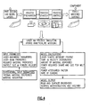
Figure 4 is a process flow chart. -
Figure 5 is an example airfoil. -
Figure 6A shows a first density of material. -
Figure 6B shows a second density of material. - A
gas turbine engine 210 is shown inFigure 1A . As shown, theengine 210 includes a fan 250 (which includes a plurality of fan blades 20), a compressor section 254 (which includes both alow pressure compressor 256 and a high pressure compressor 258), acombustor 260, and a turbine section 262 (which includes both ahigh pressure turbine 264 and a low pressure turbine 266). Thehigh pressure compressor 258 is driven, via afirst spool 268, by thehigh pressure turbine 264. Thelow pressure compressor 256 is driven, via asecond spool 270, by thelow pressure turbine 266. Also driven by thelow pressure turbine 266 are thefan blades 20 of thefan 250, which fan is coupled to thesecond spool 270 via agear 272. - The
fan 250 delivers air intocompressor section 254. Air compressed by the compressor section is delivered intocombustor 260. Products of the combustion in the combustor pass downstream overturbine section 262. - A
fan blade 20 is illustrated inFigure 1B having anairfoil 18 extending radially outwardly from adovetail 24. A leadingedge 21 and atrailing edge 22 define the forward and rear limits of theairfoil 18. - As shown in
Figure 2 , afan rotor 16 receives thedovetail 24 to mount the fan blade with theairfoil 18 extending radially outwardly. As the rotor is driven to rotate, it carries the fan blade with it. There are higher stresses infan blade 20 adjacent to the rotor 16 (area 101 for example) than occur radially outwardly (area 103 for example). On the other hand,area 103 is potentially more exposed to impact from foreign objects. - The present application deposits the material to form the fan blade in layers. The layers provide more freedom in achieving a final airfoil design compared to prior methods. By utilizing any number of deposition techniques, the designer can control specific features of each of the layers forming the airfoil, and can even control characteristics within the airfoil.
- Returning for a moment to
Figure 1B , it may be desirable to have the fan blade structurally stronger or thicker atareas 103 at the radially outer end of theairfoil 18, compared to radiallyinner areas 101, for example. Thus, it may be desirable to have a greater percentage of hollow at the radiallyinner area 101 than is found at the radiallyouter area 103. The prior art techniques for forming fan blades have not always provided sufficient freedom in specifically designing the characteristics and operational features of the fan blade along its radial length, and between theleading edge 21 and trailingedge 22. The prior art techniques for forming fan blades have not allowed for making the blades using customized functionally gradient material, which can be referred to structurally gradient (e.g. density) or material composition gradients such as Ti 6AL4V to Ti-6Al-2Sn-4Zr-2Mo or Ti-6Al-2Sn-4Zzr-6Mo. -
Figure 3A shows a technique for forming afan blade 100 having a plurality of crossingribs 102 crossing between thesides Powder feeders first layer 301 inFigure 3A . In addition, other additive techniques for fabrication of the HFB are possible such as laser sintering of composite material e.g. PEEK or PEKK; laser or EBM powder bed. - Any number of techniques can be utilized to deposit material in layers. As one example, direct laser deposition may be utilized wherein powder is delivered in a molten pool created by laser and can be controlled to be deposited at specific locations to form the shape such as crossing
ribs 102, andsides Sides - As shown in
Figure 3B , afinishing tool 116 can then finish the internal surface of thelayer 301 prior to the entire airfoil being complete. As an example, super-finishing such as REM finishing can be utilized to finish the internal surface of theintermediate layer 301 after it has been formed, to prevent crack initiation or propagation during the depositing of additional layers. Other surface finishing techniques can be also used including 5-axis machining of internal contour profile. Finishing the blades with an internal lattice structure that are made by additive manufacturing will be depending on the specific application design requirements, hence the surface finish of the lattice may be acceptable or may require a better finish. If cold spray process was used as additive manufacturing of the blade, post-thermal processing (e.g. variations in heat treatment) will be used to obtain the required grain size and mechanical properties. Controlled processing atmosphere will be used for optimum post-thermal mechanical processing. Heated, powder deposition chamber results in the equiax structure and minimal post-processing will be needed. - A minimum amount of material may be removed from the internal surfaces to achieve a desired lattice size. External surfaces could be finished using a multiple axis milling machine to obtain required surface finish. Deep rolling peening processes can then be used to induce compressive residual stress and enhance the hollow fan blade surface resistance to shock loads and to torqueing environment.
- As shown in
Figure 3C ,subsequent layers 120 have now been deposited, and an airfoil is beginning to develop. -
Figure 3D shows the addition of even more layers, such as layers 130. It should be understood that there could be any number of layers (hundreds for example) in the complete airfoil. Only three distinct layers are illustrated, however, the radial width of the layers can be controlled as desired to achieve desired density and material characteristics along the entire radial length of the airfoil. -
Figure 3E shows a subsequent step where atop end 150 closes off theinternal cavities 300 such as formed bywebs 102 shown inFigure 3D . Now, acomplete airfoil 160 is formed. It should be understood that theroot 24 as shown inFigure 1B can also be formed by this process, or any other process. - While the direct laser deposition is disclosed as one method of depositing the material in layers, other methods such as powder bed deposition, electron-beam deposition, direct metal deposition, or any number of other deposition manufacturing processes may be utilized.
- As shown in
Figure 4 , a design process for utilizing the method as described inFigures 3A-3E , would start with input of experimental parameters such as desired thermal material properties and material absorptive properties. - In the proposed modeling process, a laser additive manufacturing process is used, however, the same modeling frame can be used to define and optimize the process parameters, The mathematical approach will depend on the process physics. In the presented example, laser machine parameters, laser beam properties, required material properties, such as particle size and powder velocity, would also be input into the method.
- A laser process simulation and a hybrid analytical modeling may then be utilized.
- The designer may then design laser intensity profiles, temperature and velocity distribution, the amount of material to be deposited at each layer, the required shape and size of the powder to achieve a desired melt pool to result in the desired shape would also be developed, A power attenuation factor and the rate of cooling would also be factors to be considered at this point along with any number of other factors which may be appropriate.
- A model output may then be sent to a control for the deposition process.
-
Figure 5 shows features such asareas 170 which may desirably have 100 % density,area 172 which may desirably have a density of 75%, and a web atarea 174 which may have a 50 % density. The prior art methods had difficulty achieving controlled density at each of the distinct layers in an airfoil, and the deposition of the material in layers as achieved by this application provides that ability. -
Figure 6A shows an example of 20% density material, whileFigure 6B shows 40 % density material. Again, a worker in the art of layer deposition would know how to achieve a desired density. It is the application of such techniques through the formation of airfoil structures which is unique in this application. - Although embodiments of this invention have been disclosed, a worker of ordinary skill in this art would recognize that certain modifications would come within the scope of this invention. For that reason, the following claims should be studied to determine the true scope and content of this invention.
Claims (12)
- A method of forming an airfoil (160) comprising the step of:depositing material to form an airfoil (160) in a first layer (301), andthen depositing material in a second layer (120) on said first layer (301), wherein said first and second layers (120, 301) have distinct densities characterised in that:said first layer (301) is radially inward of said second layer (120) and said first layer (301) has a greater density than said second layer (120).
- The method as set forth in claim 1, wherein direct laser deposition is utilized to deposit the first and second layers (120, 301).
- The method as set forth in claims 1 or 2, wherein machining of internal cavities (300) within the first layer (301) occurs before the deposition of the second layer (120).
- The method as set forth in any preceding claim, wherein a top layer is deposited which closes off internal cavities (300) within said airfoil (160) to define a radially outer end (150) of the airfoil (160).
- The method as set forth in claim 4, wherein internal machining is provided on the internal cavities (300) within the airfoil (160) prior to the deposition of the top layer.
- The method as set forth in claim 4 or 5, wherein deep rolling peening processes are provided on the airfoil (160) to induce compressive residual stress.
- The method as set forth in any of claims 4 to 6, wherein external surfaces of the airfoil (160) defining suction and pressure sizes are subject to surface finishing techniques after the deposition of the top layer.
- The method as set forth in any preceding claim, wherein the airfoil (160) is part of a fan blade (20) for a gas turbine engine (210).
- The method as set forth in any preceding claim, wherein said first layer (301) and said second layer (120) include side walls (104, 106), with ribs (102) crossing between said side walls (104, 106).
- An airfoil (160) comprising an airfoil body extending between a radially inner end and a radially outer end, said airfoil (160) comprising a plurality of layers (301,120), wherein said layers (301, 120) have different densities, such that the density of said airfoil (160) varies from said radially inner end to said radially outer end,
characterised in that:said plurality of layers comprises first and second layers (301, 120), said first layer (301) is radially inward of said second layer (120) and said first layer (301) has a greater density than said second layer (120). - The airfoil (160) as set forth in claim 10, wherein a top layer closes off internal cavities (300) within said airfoil (160) to define a radially outer end of the airfoil (160).
- The airfoil (160) as set forth in claim 10 or 11, wherein the airfoil (160) is part of a fan blade (20) for a gas turbine engine (210).
Applications Claiming Priority (1)
| Application Number | Priority Date | Filing Date | Title |
|---|---|---|---|
| US13/360,753 US11000899B2 (en) | 2012-01-29 | 2012-01-29 | Hollow airfoil construction utilizing functionally graded materials |
Publications (2)
| Publication Number | Publication Date |
|---|---|
| EP2620240A1 EP2620240A1 (en) | 2013-07-31 |
| EP2620240B1 true EP2620240B1 (en) | 2015-09-09 |
Family
ID=47520855
Family Applications (1)
| Application Number | Title | Priority Date | Filing Date |
|---|---|---|---|
| EP13151444.0A Revoked EP2620240B1 (en) | 2012-01-29 | 2013-01-16 | Hollow airfoil construction utilizing functionally graded materials |
Country Status (2)
| Country | Link |
|---|---|
| US (1) | US11000899B2 (en) |
| EP (1) | EP2620240B1 (en) |
Cited By (1)
| Publication number | Priority date | Publication date | Assignee | Title |
|---|---|---|---|---|
| US10150260B2 (en) | 2016-03-08 | 2018-12-11 | General Electric Company | Method and apparatus for dispensing refrigerated fiber prepreg rolls |
Families Citing this family (27)
| Publication number | Priority date | Publication date | Assignee | Title |
|---|---|---|---|---|
| DE102011108957B4 (en) * | 2011-07-29 | 2013-07-04 | Mtu Aero Engines Gmbh | A method for producing, repairing and / or replacing a housing, in particular an engine housing, and a corresponding housing |
| ITFI20120035A1 (en) * | 2012-02-23 | 2013-08-24 | Nuovo Pignone Srl | "IMPELLER PRODUCTION FOR TURBO-MACHINES" |
| ITCO20120059A1 (en) * | 2012-12-13 | 2014-06-14 | Nuovo Pignone Srl | METHODS FOR MANUFACTURING SHAPED SHAPED LOAFERS IN 3D OF TURBOMACCHINE BY ADDITIVE PRODUCTION, TURBOMACCHINA CAVE BLOCK AND TURBOMACCHINE |
| US10710161B2 (en) * | 2013-03-11 | 2020-07-14 | Raytheon Technologies Corporation | Turbine disk fabrication with in situ material property variation |
| US9103035B2 (en) * | 2013-04-10 | 2015-08-11 | General Electric Company | Erosion resistant coating systems and processes therefor |
| EP2843192B1 (en) * | 2013-08-28 | 2021-03-24 | Safran Aero Boosters SA | Composite blade made by additive manufacturing and associated manufacturing process |
| EP2843193B1 (en) * | 2013-08-28 | 2020-08-12 | Safran Aero Boosters SA | Composite blade made by additive manufacturing and corresponding manufacturing process |
| EP3055091A4 (en) * | 2013-10-09 | 2017-07-05 | United Technologies Corporation | Multi-density, multi-property turbine component |
| US20160281510A1 (en) * | 2013-11-14 | 2016-09-29 | General Electric Company | Turbine components with negative cte features |
| CN105705278B (en) | 2013-11-14 | 2018-06-22 | 通用电气公司 | The Layered manufacturing of single crystal alloy component |
| WO2015094636A1 (en) | 2013-12-16 | 2015-06-25 | United Technologies Corporation | Gas turbine engine blade with ceramic tip and cooling arrangement |
| US9649690B2 (en) * | 2014-02-25 | 2017-05-16 | General Electric Company | System having layered structure and method of making the same |
| JP6548462B2 (en) * | 2014-06-17 | 2019-07-24 | ユナイテッド テクノロジーズ コーポレイションUnited Technologies Corporation | Additional manufacturing method |
| GB201420717D0 (en) | 2014-11-21 | 2015-01-07 | Renishaw Plc | Additive manufacturing apparatus and methods |
| ES2989689T3 (en) * | 2015-03-12 | 2024-11-27 | Limacorporate Spa | Quality control method for regulating the operation of an electromechanical device, for example, an EBM device, in order to obtain certified processed products. |
| FR3034038B1 (en) * | 2015-03-23 | 2017-11-17 | Snecma | METHOD OF MANUFACTURING AN AUBE WINDOW FOR CALIBRATING A TOMOGRAPHIC CONTROL AND AUBE WITNESS RESULTING THEREFROM |
| US10371163B2 (en) | 2016-02-02 | 2019-08-06 | General Electric Company | Load absorption systems and methods |
| CN107263019A (en) * | 2016-04-08 | 2017-10-20 | 西门子公司 | Mixed production method and corresponding product for manufacturing product |
| US10786883B2 (en) | 2016-12-20 | 2020-09-29 | United Technologies Corporation | Deep rolling tool and method |
| DE102017200233B4 (en) * | 2017-01-10 | 2022-05-05 | Sauer Gmbh | PROCESS FOR REDUCING OR COMPLETELY CLOSING AN OPENING OF A WORKPIECE'S INTERNAL CONTOUR USING A MATERIAL MOLTEN BY A LASER DEPOSITION WELDING DEVICE |
| US10808545B2 (en) * | 2017-07-14 | 2020-10-20 | United Technologies Corporation | Gas turbine engine fan blade, design, and fabrication |
| US10633976B2 (en) * | 2017-07-25 | 2020-04-28 | Bell Helicopter Textron Inc. | Methods of customizing, manufacturing, and repairing a rotor blade using additive manufacturing processes |
| FR3069481B1 (en) * | 2017-07-28 | 2021-05-28 | Airbus Helicopters | METHOD OF MANUFACTURING A BODY FOR FILLING A ROTOR BLADE AND FILLING BODY OF A ROTOR BLADE CONTAINING AT LEAST ONE CLOSED CELL ALVEOLAR ASSEMBLY |
| CN108035458B (en) * | 2018-01-26 | 2023-12-08 | 上海言诺建筑材料有限公司 | 3D printing wall structure and manufacturing method thereof |
| CN108480629B (en) * | 2018-03-23 | 2020-08-25 | 山东矿机集团股份有限公司 | Laser additive manufacturing method for hollow blade of steam turbine |
| US11174744B2 (en) | 2018-10-01 | 2021-11-16 | Raytheon Technologies Corporation | Multi-material rotor for attritable engines |
| CN109746443A (en) * | 2018-12-29 | 2019-05-14 | 华中科技大学 | A kind of method of parallel control part deformation and precision during increasing material manufacturing |
Family Cites Families (32)
| Publication number | Priority date | Publication date | Assignee | Title |
|---|---|---|---|---|
| DE2742816C3 (en) | 1977-09-23 | 1980-10-16 | Mtu Motoren- Und Turbinen-Union Muenchen Gmbh, 8000 Muenchen | Process for the production of silicon-ceramic components |
| US5038014A (en) | 1989-02-08 | 1991-08-06 | General Electric Company | Fabrication of components by layered deposition |
| IL92428A (en) | 1989-02-08 | 1992-12-01 | Gen Electric | Fabrication of components by layered deposition |
| FR2739045B1 (en) | 1995-09-27 | 1997-10-31 | Snecma | PROCESS FOR MANUFACTURING A HOLLOW BLADE OF A TURBOMACHINE |
| US6046426A (en) | 1996-07-08 | 2000-04-04 | Sandia Corporation | Method and system for producing complex-shape objects |
| US5839882A (en) | 1997-04-25 | 1998-11-24 | General Electric Company | Gas turbine blade having areas of different densities |
| US6355086B2 (en) | 1997-08-12 | 2002-03-12 | Rolls-Royce Corporation | Method and apparatus for making components by direct laser processing |
| US6641907B1 (en) | 1999-12-20 | 2003-11-04 | Siemens Westinghouse Power Corporation | High temperature erosion resistant coating and material containing compacted hollow geometric shapes |
| US6269540B1 (en) | 1998-10-05 | 2001-08-07 | National Research Council Of Canada | Process for manufacturing or repairing turbine engine or compressor components |
| US6251315B1 (en) | 1998-11-20 | 2001-06-26 | United Technologies Corporation | Method for disposing a laser blocking material on the interior of an airfoil |
| US6391251B1 (en) | 1999-07-07 | 2002-05-21 | Optomec Design Company | Forming structures from CAD solid models |
| DE50013334D1 (en) * | 2000-09-14 | 2006-09-28 | Siemens Ag | Apparatus and method for producing a blade for a turbine as well as correspondingly produced blade |
| US6607358B2 (en) | 2002-01-08 | 2003-08-19 | General Electric Company | Multi-component hybrid turbine blade |
| DE10243415A1 (en) | 2002-09-18 | 2004-04-01 | Alstom (Switzerland) Ltd. | Process for the generation of residual compressive stresses in the surface of workpieces |
| EP1533113A1 (en) | 2003-11-14 | 2005-05-25 | Siemens Aktiengesellschaft | High temperature layered system for heat dissipation and method for making it |
| GB0420578D0 (en) | 2004-09-16 | 2004-10-20 | Rolls Royce Plc | Forming structures by laser deposition |
| US8349396B2 (en) | 2005-04-14 | 2013-01-08 | United Technologies Corporation | Method and system for creating functionally graded materials using cold spray |
| US20070003416A1 (en) | 2005-06-30 | 2007-01-04 | General Electric Company | Niobium silicide-based turbine components, and related methods for laser deposition |
| WO2007055864A2 (en) * | 2005-10-12 | 2007-05-18 | Surface Technology Holdings, Ltd | Improved integrally bladed rotating turbo machinery and method and apparatus for achieving the same |
| FR2893268B1 (en) | 2005-11-15 | 2008-02-08 | Snecma Sa | METHOD OF MAKING A REBORD LOCATED AT THE FREE END OF A DAWN, DAWN OBTAINED BY THIS PROCESS AND TURBOMACHINE EQUIPPED WITH SAID DARK |
| GB0709838D0 (en) | 2007-05-23 | 2007-07-04 | Rolls Royce Plc | A hollow blade and a method of manufacturing a hollow blade |
| US7967570B2 (en) | 2007-07-27 | 2011-06-28 | United Technologies Corporation | Low transient thermal stress turbine engine components |
| US8066483B1 (en) | 2008-12-18 | 2011-11-29 | Florida Turbine Technologies, Inc. | Turbine airfoil with non-parallel pin fins |
| US20100200189A1 (en) | 2009-02-12 | 2010-08-12 | General Electric Company | Method of fabricating turbine airfoils and tip structures therefor |
| US20100242843A1 (en) | 2009-03-24 | 2010-09-30 | Peretti Michael W | High temperature additive manufacturing systems for making near net shape airfoils leading edge protection, and tooling systems therewith |
| DE112010002686T5 (en) * | 2009-06-23 | 2013-01-03 | Panasonic Corporation | A method of manufacturing a three-dimensional molded article and a three-dimensional molded article produced by this method |
| US8987629B2 (en) | 2009-07-29 | 2015-03-24 | General Electric Company | Process of closing an opening in a component |
| DE102009048665A1 (en) | 2009-09-28 | 2011-03-31 | Siemens Aktiengesellschaft | Turbine blade and method for its production |
| DE102009051479A1 (en) | 2009-10-30 | 2011-05-05 | Mtu Aero Engines Gmbh | Method and device for producing a component of a turbomachine |
| EP2319641B1 (en) | 2009-10-30 | 2017-07-19 | Ansaldo Energia IP UK Limited | Method to apply multiple materials with selective laser melting on a 3D article |
| US8979498B2 (en) * | 2010-03-03 | 2015-03-17 | Siemens Energy, Inc. | Turbine airfoil having outboard and inboard sections |
| US8506836B2 (en) | 2011-09-16 | 2013-08-13 | Honeywell International Inc. | Methods for manufacturing components from articles formed by additive-manufacturing processes |
-
2012
- 2012-01-29 US US13/360,753 patent/US11000899B2/en active Active
-
2013
- 2013-01-16 EP EP13151444.0A patent/EP2620240B1/en not_active Revoked
Cited By (1)
| Publication number | Priority date | Publication date | Assignee | Title |
|---|---|---|---|---|
| US10150260B2 (en) | 2016-03-08 | 2018-12-11 | General Electric Company | Method and apparatus for dispensing refrigerated fiber prepreg rolls |
Also Published As
| Publication number | Publication date |
|---|---|
| US11000899B2 (en) | 2021-05-11 |
| EP2620240A1 (en) | 2013-07-31 |
| US20130195671A1 (en) | 2013-08-01 |
Similar Documents
| Publication | Publication Date | Title |
|---|---|---|
| US11000899B2 (en) | Hollow airfoil construction utilizing functionally graded materials | |
| US10710161B2 (en) | Turbine disk fabrication with in situ material property variation | |
| EP2663414B1 (en) | Method for the generative production of a component with an integrated damping element for a turbomachine, and a component produced in a generative manner with an integrated damping element for a turbomachine | |
| EP3702069B1 (en) | Titanium aluminide components from articles formed by consolidation processes | |
| US9903214B2 (en) | Internally cooled turbine blisk and method of manufacture | |
| US11459905B2 (en) | Duct with additive manufactured seal | |
| CN113153441B (en) | Additively manufactured turbine rotor blade having a platform with nonlinear cooling channels | |
| CN114867930B (en) | Turbine rotor blades with airfoil seals and coolant transfer channels between adjacent wheel space portions, manufactured by additive manufacturing. | |
| ITFI20120035A1 (en) | "IMPELLER PRODUCTION FOR TURBO-MACHINES" | |
| US10837287B2 (en) | Mistuned bladed rotor and associated manufacturing method | |
| CA2948252C (en) | Turbine airfoil with passive morphing structure | |
| US20170248319A1 (en) | System having layered structure and method of making the same | |
| EP3284916B1 (en) | A component for a gas turbine engine and method of manufacture | |
| EP3115131B1 (en) | Manufacture of component with cooling channels | |
| EP2930309B1 (en) | Method of forming a cooled wall segment of a gas turbine engine | |
| US11105212B2 (en) | Gas turbine engines including tangential on-board injectors and methods for manufacturing the same | |
| EP2841700B1 (en) | Airfoil support method and apparatus | |
| CN113153440B (en) | Additively manufactured turbine rotor blade root with hollow mounting frame with grid support structure | |
| EP3983225B1 (en) | Method for preparing powder bed based additive manufacturing process and corresponding computer program product | |
| WO2016087337A1 (en) | Method for producing a vibration damper for a turbine blade by means of laser generation | |
| EP4031310A1 (en) | Method for the layer-by-layer additive manufacturing of a composite material | |
| EP3348788B1 (en) | Additively manufactured component for a gas powered turbine | |
| EP3009212B1 (en) | Manufacturing method of a leading edge of an aerofoil component |
Legal Events
| Date | Code | Title | Description |
|---|---|---|---|
| PUAI | Public reference made under article 153(3) epc to a published international application that has entered the european phase |
Free format text: ORIGINAL CODE: 0009012 |
|
| AK | Designated contracting states |
Kind code of ref document: A1 Designated state(s): AL AT BE BG CH CY CZ DE DK EE ES FI FR GB GR HR HU IE IS IT LI LT LU LV MC MK MT NL NO PL PT RO RS SE SI SK SM TR |
|
| AX | Request for extension of the european patent |
Extension state: BA ME |
|
| 17P | Request for examination filed |
Effective date: 20131211 |
|
| RBV | Designated contracting states (corrected) |
Designated state(s): AL AT BE BG CH CY CZ DE DK EE ES FI FR GB GR HR HU IE IS IT LI LT LU LV MC MK MT NL NO PL PT RO RS SE SI SK SM TR |
|
| 17Q | First examination report despatched |
Effective date: 20140415 |
|
| GRAP | Despatch of communication of intention to grant a patent |
Free format text: ORIGINAL CODE: EPIDOSNIGR1 |
|
| INTG | Intention to grant announced |
Effective date: 20150326 |
|
| GRAS | Grant fee paid |
Free format text: ORIGINAL CODE: EPIDOSNIGR3 |
|
| GRAA | (expected) grant |
Free format text: ORIGINAL CODE: 0009210 |
|
| AK | Designated contracting states |
Kind code of ref document: B1 Designated state(s): AL AT BE BG CH CY CZ DE DK EE ES FI FR GB GR HR HU IE IS IT LI LT LU LV MC MK MT NL NO PL PT RO RS SE SI SK SM TR |
|
| REG | Reference to a national code |
Ref country code: GB Ref legal event code: FG4D |
|
| REG | Reference to a national code |
Ref country code: AT Ref legal event code: REF Ref document number: 747704 Country of ref document: AT Kind code of ref document: T Effective date: 20150915 Ref country code: CH Ref legal event code: EP |
|
| REG | Reference to a national code |
Ref country code: IE Ref legal event code: FG4D |
|
| REG | Reference to a national code |
Ref country code: DE Ref legal event code: R096 Ref document number: 602013002870 Country of ref document: DE |
|
| REG | Reference to a national code |
Ref country code: NL Ref legal event code: MP Effective date: 20150909 |
|
| PG25 | Lapsed in a contracting state [announced via postgrant information from national office to epo] |
Ref country code: LT Free format text: LAPSE BECAUSE OF FAILURE TO SUBMIT A TRANSLATION OF THE DESCRIPTION OR TO PAY THE FEE WITHIN THE PRESCRIBED TIME-LIMIT Effective date: 20150909 Ref country code: LV Free format text: LAPSE BECAUSE OF FAILURE TO SUBMIT A TRANSLATION OF THE DESCRIPTION OR TO PAY THE FEE WITHIN THE PRESCRIBED TIME-LIMIT Effective date: 20150909 Ref country code: FI Free format text: LAPSE BECAUSE OF FAILURE TO SUBMIT A TRANSLATION OF THE DESCRIPTION OR TO PAY THE FEE WITHIN THE PRESCRIBED TIME-LIMIT Effective date: 20150909 Ref country code: NO Free format text: LAPSE BECAUSE OF FAILURE TO SUBMIT A TRANSLATION OF THE DESCRIPTION OR TO PAY THE FEE WITHIN THE PRESCRIBED TIME-LIMIT Effective date: 20151209 Ref country code: GR Free format text: LAPSE BECAUSE OF FAILURE TO SUBMIT A TRANSLATION OF THE DESCRIPTION OR TO PAY THE FEE WITHIN THE PRESCRIBED TIME-LIMIT Effective date: 20151210 |
|
| REG | Reference to a national code |
Ref country code: LT Ref legal event code: MG4D |
|
| REG | Reference to a national code |
Ref country code: AT Ref legal event code: MK05 Ref document number: 747704 Country of ref document: AT Kind code of ref document: T Effective date: 20150909 |
|
| PG25 | Lapsed in a contracting state [announced via postgrant information from national office to epo] |
Ref country code: SE Free format text: LAPSE BECAUSE OF FAILURE TO SUBMIT A TRANSLATION OF THE DESCRIPTION OR TO PAY THE FEE WITHIN THE PRESCRIBED TIME-LIMIT Effective date: 20150909 Ref country code: HR Free format text: LAPSE BECAUSE OF FAILURE TO SUBMIT A TRANSLATION OF THE DESCRIPTION OR TO PAY THE FEE WITHIN THE PRESCRIBED TIME-LIMIT Effective date: 20150909 Ref country code: RS Free format text: LAPSE BECAUSE OF FAILURE TO SUBMIT A TRANSLATION OF THE DESCRIPTION OR TO PAY THE FEE WITHIN THE PRESCRIBED TIME-LIMIT Effective date: 20150909 Ref country code: ES Free format text: LAPSE BECAUSE OF FAILURE TO SUBMIT A TRANSLATION OF THE DESCRIPTION OR TO PAY THE FEE WITHIN THE PRESCRIBED TIME-LIMIT Effective date: 20150909 |
|
| PG25 | Lapsed in a contracting state [announced via postgrant information from national office to epo] |
Ref country code: NL Free format text: LAPSE BECAUSE OF FAILURE TO SUBMIT A TRANSLATION OF THE DESCRIPTION OR TO PAY THE FEE WITHIN THE PRESCRIBED TIME-LIMIT Effective date: 20150909 |
|
| PG25 | Lapsed in a contracting state [announced via postgrant information from national office to epo] |
Ref country code: EE Free format text: LAPSE BECAUSE OF FAILURE TO SUBMIT A TRANSLATION OF THE DESCRIPTION OR TO PAY THE FEE WITHIN THE PRESCRIBED TIME-LIMIT Effective date: 20150909 Ref country code: SK Free format text: LAPSE BECAUSE OF FAILURE TO SUBMIT A TRANSLATION OF THE DESCRIPTION OR TO PAY THE FEE WITHIN THE PRESCRIBED TIME-LIMIT Effective date: 20150909 Ref country code: IT Free format text: LAPSE BECAUSE OF FAILURE TO SUBMIT A TRANSLATION OF THE DESCRIPTION OR TO PAY THE FEE WITHIN THE PRESCRIBED TIME-LIMIT Effective date: 20150909 Ref country code: CZ Free format text: LAPSE BECAUSE OF FAILURE TO SUBMIT A TRANSLATION OF THE DESCRIPTION OR TO PAY THE FEE WITHIN THE PRESCRIBED TIME-LIMIT Effective date: 20150909 Ref country code: IS Free format text: LAPSE BECAUSE OF FAILURE TO SUBMIT A TRANSLATION OF THE DESCRIPTION OR TO PAY THE FEE WITHIN THE PRESCRIBED TIME-LIMIT Effective date: 20160109 |
|
| PG25 | Lapsed in a contracting state [announced via postgrant information from national office to epo] |
Ref country code: PL Free format text: LAPSE BECAUSE OF FAILURE TO SUBMIT A TRANSLATION OF THE DESCRIPTION OR TO PAY THE FEE WITHIN THE PRESCRIBED TIME-LIMIT Effective date: 20150909 Ref country code: BE Free format text: LAPSE BECAUSE OF NON-PAYMENT OF DUE FEES Effective date: 20160131 Ref country code: PT Free format text: LAPSE BECAUSE OF FAILURE TO SUBMIT A TRANSLATION OF THE DESCRIPTION OR TO PAY THE FEE WITHIN THE PRESCRIBED TIME-LIMIT Effective date: 20160111 Ref country code: RO Free format text: LAPSE BECAUSE OF FAILURE TO SUBMIT A TRANSLATION OF THE DESCRIPTION OR TO PAY THE FEE WITHIN THE PRESCRIBED TIME-LIMIT Effective date: 20150909 Ref country code: AT Free format text: LAPSE BECAUSE OF FAILURE TO SUBMIT A TRANSLATION OF THE DESCRIPTION OR TO PAY THE FEE WITHIN THE PRESCRIBED TIME-LIMIT Effective date: 20150909 |
|
| REG | Reference to a national code |
Ref country code: DE Ref legal event code: R026 Ref document number: 602013002870 Country of ref document: DE |
|
| PLBI | Opposition filed |
Free format text: ORIGINAL CODE: 0009260 |
|
| 26 | Opposition filed |
Opponent name: SIEMENS AKTIENGESELLSCHAFT Effective date: 20160608 Opponent name: SNECMA Effective date: 20160603 |
|
| PLAX | Notice of opposition and request to file observation + time limit sent |
Free format text: ORIGINAL CODE: EPIDOSNOBS2 |
|
| PG25 | Lapsed in a contracting state [announced via postgrant information from national office to epo] |
Ref country code: DK Free format text: LAPSE BECAUSE OF FAILURE TO SUBMIT A TRANSLATION OF THE DESCRIPTION OR TO PAY THE FEE WITHIN THE PRESCRIBED TIME-LIMIT Effective date: 20150909 Ref country code: SI Free format text: LAPSE BECAUSE OF FAILURE TO SUBMIT A TRANSLATION OF THE DESCRIPTION OR TO PAY THE FEE WITHIN THE PRESCRIBED TIME-LIMIT Effective date: 20150909 Ref country code: LU Free format text: LAPSE BECAUSE OF FAILURE TO SUBMIT A TRANSLATION OF THE DESCRIPTION OR TO PAY THE FEE WITHIN THE PRESCRIBED TIME-LIMIT Effective date: 20160116 |
|
| REG | Reference to a national code |
Ref country code: CH Ref legal event code: PL |
|
| PG25 | Lapsed in a contracting state [announced via postgrant information from national office to epo] |
Ref country code: MC Free format text: LAPSE BECAUSE OF FAILURE TO SUBMIT A TRANSLATION OF THE DESCRIPTION OR TO PAY THE FEE WITHIN THE PRESCRIBED TIME-LIMIT Effective date: 20150909 |
|
| RAP2 | Party data changed (patent owner data changed or rights of a patent transferred) |
Owner name: UNITED TECHNOLOGIES CORPORATION |
|
| REG | Reference to a national code |
Ref country code: FR Ref legal event code: ST Effective date: 20160930 |
|
| PG25 | Lapsed in a contracting state [announced via postgrant information from national office to epo] |
Ref country code: CH Free format text: LAPSE BECAUSE OF NON-PAYMENT OF DUE FEES Effective date: 20160131 Ref country code: LI Free format text: LAPSE BECAUSE OF NON-PAYMENT OF DUE FEES Effective date: 20160131 |
|
| REG | Reference to a national code |
Ref country code: IE Ref legal event code: MM4A |
|
| PLAB | Opposition data, opponent's data or that of the opponent's representative modified |
Free format text: ORIGINAL CODE: 0009299OPPO |
|
| PG25 | Lapsed in a contracting state [announced via postgrant information from national office to epo] |
Ref country code: FR Free format text: LAPSE BECAUSE OF NON-PAYMENT OF DUE FEES Effective date: 20160201 |
|
| PLBB | Reply of patent proprietor to notice(s) of opposition received |
Free format text: ORIGINAL CODE: EPIDOSNOBS3 |
|
| R26 | Opposition filed (corrected) |
Opponent name: SAFRAN AIRCRAFT ENGINES Effective date: 20160603 |
|
| PG25 | Lapsed in a contracting state [announced via postgrant information from national office to epo] |
Ref country code: BE Free format text: LAPSE BECAUSE OF FAILURE TO SUBMIT A TRANSLATION OF THE DESCRIPTION OR TO PAY THE FEE WITHIN THE PRESCRIBED TIME-LIMIT Effective date: 20150909 |
|
| PG25 | Lapsed in a contracting state [announced via postgrant information from national office to epo] |
Ref country code: IE Free format text: LAPSE BECAUSE OF NON-PAYMENT OF DUE FEES Effective date: 20160116 |
|
| REG | Reference to a national code |
Ref country code: DE Ref legal event code: R082 Ref document number: 602013002870 Country of ref document: DE Representative=s name: SCHMITT-NILSON SCHRAUD WAIBEL WOHLFROM PATENTA, DE |
|
| REG | Reference to a national code |
Ref country code: DE Ref legal event code: R082 Ref document number: 602013002870 Country of ref document: DE Representative=s name: SCHMITT-NILSON SCHRAUD WAIBEL WOHLFROM PATENTA, DE Ref country code: DE Ref legal event code: R081 Ref document number: 602013002870 Country of ref document: DE Owner name: UNITED TECHNOLOGIES CORP. (N.D.GES.D. STAATES , US Free format text: FORMER OWNER: UNITED TECHNOLOGIES CORP., HARTFORD, CONN., US |
|
| PG25 | Lapsed in a contracting state [announced via postgrant information from national office to epo] |
Ref country code: MT Free format text: LAPSE BECAUSE OF FAILURE TO SUBMIT A TRANSLATION OF THE DESCRIPTION OR TO PAY THE FEE WITHIN THE PRESCRIBED TIME-LIMIT Effective date: 20150909 |
|
| PLAB | Opposition data, opponent's data or that of the opponent's representative modified |
Free format text: ORIGINAL CODE: 0009299OPPO |
|
| R26 | Opposition filed (corrected) |
Opponent name: SIEMENS AKTIENGESELLSCHAFT Effective date: 20160608 |
|
| RDAF | Communication despatched that patent is revoked |
Free format text: ORIGINAL CODE: EPIDOSNREV1 |
|
| STAA | Information on the status of an ep patent application or granted ep patent |
Free format text: STATUS: THE PATENT HAS BEEN GRANTED |
|
| PG25 | Lapsed in a contracting state [announced via postgrant information from national office to epo] |
Ref country code: SM Free format text: LAPSE BECAUSE OF FAILURE TO SUBMIT A TRANSLATION OF THE DESCRIPTION OR TO PAY THE FEE WITHIN THE PRESCRIBED TIME-LIMIT Effective date: 20150909 Ref country code: HU Free format text: LAPSE BECAUSE OF FAILURE TO SUBMIT A TRANSLATION OF THE DESCRIPTION OR TO PAY THE FEE WITHIN THE PRESCRIBED TIME-LIMIT; INVALID AB INITIO Effective date: 20130116 Ref country code: CY Free format text: LAPSE BECAUSE OF FAILURE TO SUBMIT A TRANSLATION OF THE DESCRIPTION OR TO PAY THE FEE WITHIN THE PRESCRIBED TIME-LIMIT Effective date: 20150909 |
|
| APBM | Appeal reference recorded |
Free format text: ORIGINAL CODE: EPIDOSNREFNO |
|
| APBP | Date of receipt of notice of appeal recorded |
Free format text: ORIGINAL CODE: EPIDOSNNOA2O |
|
| APAH | Appeal reference modified |
Free format text: ORIGINAL CODE: EPIDOSCREFNO |
|
| PG25 | Lapsed in a contracting state [announced via postgrant information from national office to epo] |
Ref country code: MK Free format text: LAPSE BECAUSE OF FAILURE TO SUBMIT A TRANSLATION OF THE DESCRIPTION OR TO PAY THE FEE WITHIN THE PRESCRIBED TIME-LIMIT Effective date: 20150909 Ref country code: MT Free format text: LAPSE BECAUSE OF FAILURE TO SUBMIT A TRANSLATION OF THE DESCRIPTION OR TO PAY THE FEE WITHIN THE PRESCRIBED TIME-LIMIT Effective date: 20160131 Ref country code: TR Free format text: LAPSE BECAUSE OF FAILURE TO SUBMIT A TRANSLATION OF THE DESCRIPTION OR TO PAY THE FEE WITHIN THE PRESCRIBED TIME-LIMIT Effective date: 20150909 |
|
| PG25 | Lapsed in a contracting state [announced via postgrant information from national office to epo] |
Ref country code: BG Free format text: LAPSE BECAUSE OF FAILURE TO SUBMIT A TRANSLATION OF THE DESCRIPTION OR TO PAY THE FEE WITHIN THE PRESCRIBED TIME-LIMIT Effective date: 20150909 |
|
| APBQ | Date of receipt of statement of grounds of appeal recorded |
Free format text: ORIGINAL CODE: EPIDOSNNOA3O |
|
| PG25 | Lapsed in a contracting state [announced via postgrant information from national office to epo] |
Ref country code: AL Free format text: LAPSE BECAUSE OF FAILURE TO SUBMIT A TRANSLATION OF THE DESCRIPTION OR TO PAY THE FEE WITHIN THE PRESCRIBED TIME-LIMIT Effective date: 20150909 |
|
| PLAB | Opposition data, opponent's data or that of the opponent's representative modified |
Free format text: ORIGINAL CODE: 0009299OPPO |
|
| R26 | Opposition filed (corrected) |
Opponent name: SAFRAN AIRCRAFT ENGINES Effective date: 20160603 |
|
| PGFP | Annual fee paid to national office [announced via postgrant information from national office to epo] |
Ref country code: DE Payment date: 20191218 Year of fee payment: 8 |
|
| PLAB | Opposition data, opponent's data or that of the opponent's representative modified |
Free format text: ORIGINAL CODE: 0009299OPPO |
|
| PGFP | Annual fee paid to national office [announced via postgrant information from national office to epo] |
Ref country code: GB Payment date: 20201218 Year of fee payment: 9 |
|
| REG | Reference to a national code |
Ref country code: DE Ref legal event code: R064 Ref document number: 602013002870 Country of ref document: DE Ref country code: DE Ref legal event code: R103 Ref document number: 602013002870 Country of ref document: DE |
|
| APBU | Appeal procedure closed |
Free format text: ORIGINAL CODE: EPIDOSNNOA9O |
|
| R26 | Opposition filed (corrected) |
Opponent name: SIEMENS AKTIENGESELLSCHAFT Effective date: 20160608 |
|
| RDAG | Patent revoked |
Free format text: ORIGINAL CODE: 0009271 |
|
| STAA | Information on the status of an ep patent application or granted ep patent |
Free format text: STATUS: PATENT REVOKED |
|
| PLAB | Opposition data, opponent's data or that of the opponent's representative modified |
Free format text: ORIGINAL CODE: 0009299OPPO |
|
| RAP2 | Party data changed (patent owner data changed or rights of a patent transferred) |
Owner name: RAYTHEON TECHNOLOGIES CORPORATION |
|
| REG | Reference to a national code |
Ref country code: FI Ref legal event code: MGE |
|
| 27W | Patent revoked |
Effective date: 20210129 |
|
| GBPR | Gb: patent revoked under art. 102 of the ep convention designating the uk as contracting state |
Effective date: 20210129 |
|
| REG | Reference to a national code |
Ref country code: FI Ref legal event code: MGE |
|
| R26 | Opposition filed (corrected) |
Opponent name: SIEMENS AKTIENGESELLSCHAFT Effective date: 20160608 |