EP2620178A1 - Connector for medical lines - Google Patents
Connector for medical lines Download PDFInfo
- Publication number
- EP2620178A1 EP2620178A1 EP13150798.0A EP13150798A EP2620178A1 EP 2620178 A1 EP2620178 A1 EP 2620178A1 EP 13150798 A EP13150798 A EP 13150798A EP 2620178 A1 EP2620178 A1 EP 2620178A1
- Authority
- EP
- European Patent Office
- Prior art keywords
- connector
- sleeve
- connector according
- male
- male connector
- Prior art date
- Legal status (The legal status is an assumption and is not a legal conclusion. Google has not performed a legal analysis and makes no representation as to the accuracy of the status listed.)
- Granted
Links
Images

Classifications
-
- A—HUMAN NECESSITIES
- A61—MEDICAL OR VETERINARY SCIENCE; HYGIENE
- A61M—DEVICES FOR INTRODUCING MEDIA INTO, OR ONTO, THE BODY; DEVICES FOR TRANSDUCING BODY MEDIA OR FOR TAKING MEDIA FROM THE BODY; DEVICES FOR PRODUCING OR ENDING SLEEP OR STUPOR
- A61M39/00—Tubes, tube connectors, tube couplings, valves, access sites or the like, specially adapted for medical use
- A61M39/10—Tube connectors or tube couplings
- A61M39/1011—Locking means for securing connection; Additional tamper safeties
-
- A—HUMAN NECESSITIES
- A61—MEDICAL OR VETERINARY SCIENCE; HYGIENE
- A61M—DEVICES FOR INTRODUCING MEDIA INTO, OR ONTO, THE BODY; DEVICES FOR TRANSDUCING BODY MEDIA OR FOR TAKING MEDIA FROM THE BODY; DEVICES FOR PRODUCING OR ENDING SLEEP OR STUPOR
- A61M39/00—Tubes, tube connectors, tube couplings, valves, access sites or the like, specially adapted for medical use
- A61M39/10—Tube connectors or tube couplings
- A61M2039/1016—Unlocking means providing a secure or comfortable disconnection
-
- A—HUMAN NECESSITIES
- A61—MEDICAL OR VETERINARY SCIENCE; HYGIENE
- A61M—DEVICES FOR INTRODUCING MEDIA INTO, OR ONTO, THE BODY; DEVICES FOR TRANSDUCING BODY MEDIA OR FOR TAKING MEDIA FROM THE BODY; DEVICES FOR PRODUCING OR ENDING SLEEP OR STUPOR
- A61M39/00—Tubes, tube connectors, tube couplings, valves, access sites or the like, specially adapted for medical use
- A61M39/10—Tube connectors or tube couplings
- A61M39/1033—Swivel nut connectors, e.g. threaded connectors or bayonet-connectors
-
- Y—GENERAL TAGGING OF NEW TECHNOLOGICAL DEVELOPMENTS; GENERAL TAGGING OF CROSS-SECTIONAL TECHNOLOGIES SPANNING OVER SEVERAL SECTIONS OF THE IPC; TECHNICAL SUBJECTS COVERED BY FORMER USPC CROSS-REFERENCE ART COLLECTIONS [XRACs] AND DIGESTS
- Y10—TECHNICAL SUBJECTS COVERED BY FORMER USPC
- Y10S—TECHNICAL SUBJECTS COVERED BY FORMER USPC CROSS-REFERENCE ART COLLECTIONS [XRACs] AND DIGESTS
- Y10S604/00—Surgery
- Y10S604/905—Aseptic connectors or couplings, e.g. frangible, piercable
Definitions
- the present invention relates to connectors for medical lines, for example infusion lines and transfusion lines, of the type comprising a tubular body having at one end a male connector, for example of the luer-lock type or the like, including an inner tubular element and an outer hollow element, which is internally threaded and can be coupled by screwing to a complementary female connector.
- this solution renders the line connector safer as regards any accidental unscrewing of the male connector from the female connector, for example due to yielding of the plastic material of which they are made or to phenomena of fatigue, it is altogether ineffective in the case of a wrong manoeuvre of voluntary unscrewing.
- Document EP-1747797A1 filed in the name of the present applicant, describes a medical connector equipped with a dual unidirectional coupling associated to a female luer-lock connector, which operates in the direction of screwing with respect to a complementary male connector in a first axial position and in the opposite direction of unscrewing in a second axial position of the line connector.
- This unidirectional system is integrated in the line connector and requires, for passage from the first position to the second position, axial translation of the female connector with respect to a collar rigidly fixed to the body of the line connector, against the action of an elastic body, which is also integrated within the line connector.
- the object of the present invention is thus to solve the aforesaid technical problem, and more in particular to render altogether safe the line connector in regard to any erroneous unscrewing of the male connector with respect to the complementary female connector, without the drawbacks referred to previously.
- the above object is achieved thanks to the fact that the aforesaid outer manoeuvring sleeve is free to turn in the opposite direction (i.e., in the direction of unscrewing of the line connector) and is formed by two parts coupled together on the body of the line connector.
- the manoeuvring sleeve can be applied in a simple and precise way to the line connector, substantially without any undesirable radial or axial play, and ensures maximum safety against the risk of any accidental or erroneous unscrewing of the line connector.
- the outer hollow element of the male connector has an outer ring gear, which co-operates with a ring of unidirectional pawling teeth provided inside the aforesaid outer sleeve.
- the invention envisages two different embodiments, in the first of which the outer sleeve is formed by two axial portions coupled together, and in the second of which said sleeve includes two radial half-shells, which are also coupled together.
- coupling is preferably, albeit not necessarily, obtained via members of mutual snap-action coupling.
- the tubular body of the line connector and the outer sleeve may moreover be mutually displaceable axially between a first position in which they are coupled together in unidirectional rotation in the direction of screwing of the male connector and a second position in which the outer sleeve is coupled in rotation with the body of the line connector in the direction corresponding to unscrewing of the male connector.
- valve connectors manufactured and marketed by the present applicant under the brand name "B-SITE ® ", which form the subject among other things of documents US-7784766 , US-8048038 and US-2009/292274 .
- valve connector for medical infusion lines, transfusion lines, and the like of the type corresponding to the ones described and illustrated in the patent documents referred to above filed in the name of the present applicant.
- the invention is likewise applicable to any medical-line connector equipped with a male connector, typically of the luer-lock type or the like, that can be coupled to a complementary female connector of a conventional type, which is also of the luer-lock type or the like, which, as is well known to the person skilled in the branch, basically consists of a tubular element provided with an end external thread.
- valve connector for medical lines comprising, in a way in itself known, for example from the already cited patent No. US-8,048,038 , a tubular body 2 made of moulded plastic material, set coaxially within which are a hollow pin 3 and an elastic sealing member 4 having a pre-slit elastic head 5 normally set in a closing condition within an inlet end 6 of the tubular body 2, formed by a female luer-lock connector.
- the hollow pin 3 forms at one end a closed terminal 7 facing the elastic head 5 and normally set at an axial distance therefrom, and at the opposite end a male luer-lock connector 8 constituted, in a way also in itself known, by an inner tubular element 9 with conical outer surface in communication with the hollow pin 3 and by an internally threaded outer hollow element 10.
- the male luer-lock connector 8 is coupled by screwing to a complementary female luer-lock connector, and then an introducer of fluid is coupled to the inlet connector 6 so as to press the sealing member 4 axially against the action of a hollow elastic element 11 formed integrally therewith, towards the terminal 7 so as to get the pre-slit head 5 to assume an elastically deformed condition of opening and thus enable passage of fluid from the introducer to the male luer-lock connector 8.
- the line connector further comprises an outer manoeuvring sleeve, designated as a whole by 12, which is coupled in unidirectional rotation to the body 2 in the direction corresponding to screwing of the male luer-lock connector 8 to the complementary female luer-lock connector, and is free to turn in the opposite direction.
- the outer sleeve 12 extends axially, starting from the female luer-lock connector 6, until it covers entirely the outer hollow element 10 of the male luer-lock connector 8 and, in the case described herein with reference to Figures 1 and 5 , it is formed by two axial portions 13, 14, which are also conveniently made of moulded plastic material.
- the axial portion 13 has a series of elastically sprung end legs 15 formed with respective engagement teeth 16, and the portion 14 consists of a ring that surrounds the outer hollow element 10 of the male luer-lock connector 8 and is formed externally with pawling parts 17 for snap-action engagement of the teeth 16 when the two parts 13, 14 are fitted axially in mutually opposite directions on the body 2.
- the ring that constitutes the portion 14 is moreover formed internally with a ring of elastically sprung teeth 18 (more clearly visible in Figure 4 ), with which a ring of teeth 19 formed on the outside of the hollow element 10 of the male luer-lock connector 8 co-operates.
- the arrangement of the teeth 18 and 19 is such that, as already explained previously, the outer sleeve 12 formed by the portions 13 and 14 is coupled in unidirectional rotation to the body 2 of the line connector only in the direction corresponding to screwing of the male luer-lock connector 8. In the opposite direction, the teeth 18 of the portion 14 jump elastically on the teeth 19 of the hollow element 10, thus enabling free rotation of the outer sleeve 12 with respect to the body 2 of the line connector 1. In this way, once the male luer-lock connector 8 is coupled by screwing to the complementary female luer-lock connector, it is prevented from unscrewing.
- the outer manoeuvring sleeve designated as a whole by 22, is formed by two radial half-shells 23, 24 and is mounted on the body 2 of the line connector 1 in an axially slidable way between a first position, in which the sleeve 22 is coupled in unidirectional rotation to the body 2 of the line connector 1 in the direction corresponding to screwing of the male luer-lock connector 8 to the complementary female luer-lock connector, and a second position in which said sleeve 22 is coupled in rotation to the body 2 in the opposite direction, i.e., in the direction corresponding to unscrewing of the male luer-lock connector 9.
- the two half-shells 23, 24 (which have an identical shape and can hence be obtained with a single die) also extend practically throughout the axial extension of the body 2 of the line connector starting from the female luer-lock connector 6 so as to gird at the bottom the entire outer hollow element 10 of the male luer-lock connector 8.
- the two half-shells 23, 24 are formed with respective sprung legs 25 designed to engage by snap action within corresponding openings 26 to form the sleeve 22, and each of them is moreover formed internally with respective elastically sprung teeth 27, altogether similar to the teeth 18 of the previous embodiment, which are designed to cooperate in the same way with the ring of external teeth 19 of the outer hollow element 10 of the male luer-lock connector 8.
- the teeth 27 couple the sleeve 22 torsionally to the body 2 of the line connector 1 in the direction corresponding to screwing of the luer-lock connector 8, whilst rotation of the sleeve 22 with respect to the body 2 is free in the opposite direction thanks to that the teeth 27 jump on the teeth 19.
- the sleeve 22 is moreover displaceable axially with respect to the body 2 for a limited travel, starting from the position in which the teeth 27 are set axially in a position corresponding to the teeth 19, towards an unstable position in which engagement between the teeth 27 and the teeth 19 is no longer possible whilst the sleeve 22 couples torsionally to the body 2 of the line connector 1 in the direction corresponding to unscrewing of the male luer-lock connector 8 from the complementary female luer-lock connector. Said torsional coupling is implemented, in the second axial position, as a result of engagement between further rings of external teeth 28 and internal teeth 29, respectively, of the body 2 and of the half-shells 23, 24 of the sleeve 22.
- the teeth 28 and 29 are illustrated in greater detail in Figure 11 .
- the second position corresponding to engagement between the teeth 28 and 29 is unstable in so far as it is countered by a pair of elastically sprung appendages 30 formed integrally with the respective half-shells 23, 24 and engaged within corresponding recesses 31 of the body 2 of the line connector 1.
- the sprung appendages 30 bring it back into the first position, thus obtaining disengagement between the teeth 28 and 29 and restoring engagement between the teeth 27 and 19.
- valve connector 1 represented in the drawings but to any medical connector equipped with a male connector of the luer-lock type or similar types, which have a tubular element with conical outer surface that can engage with a female connector of a similar type (hence not necessarily a luer-lock connector).
- the other end of the line connector i.e., the one opposite to the male connector, may be of any kind, for example formed by a simple duct applied even permanently to the body of the line connector.
- the male connector of the line connector instead of being of the luer-lock type, may be of any different type equipped with an inner tubular element with conical outer surface.
- the union between the two axial portions 13, 14 or between the two radial half-shells 23, 24 may be obtained, instead of via snap-action couplings, with any different system, as likewise the elastic system that tends to keep the outer sleeve and the body of the line connector in the position of mutual unidirectional coupling in the direction of screwing may be different.
Landscapes
- Health & Medical Sciences (AREA)
- Heart & Thoracic Surgery (AREA)
- Pulmonology (AREA)
- Engineering & Computer Science (AREA)
- Anesthesiology (AREA)
- Biomedical Technology (AREA)
- Hematology (AREA)
- Life Sciences & Earth Sciences (AREA)
- Animal Behavior & Ethology (AREA)
- General Health & Medical Sciences (AREA)
- Public Health (AREA)
- Veterinary Medicine (AREA)
- Infusion, Injection, And Reservoir Apparatuses (AREA)
Abstract
Description
- The present invention relates to connectors for medical lines, for example infusion lines and transfusion lines, of the type comprising a tubular body having at one end a male connector, for example of the luer-lock type or the like, including an inner tubular element and an outer hollow element, which is internally threaded and can be coupled by screwing to a complementary female connector.
- In connectors of the type defined above, once the male connector is coupled and screwed to the complementary female connector there is the risk that the two connectors might come unscrewed and separate either accidentally or on account of a false manoeuvre, which evidently entails leakages of fluid and risks of even critical consequences for the patient to whom the connector is connected in use.
- In an attempt to solve this problem it has been proposed in
US-5,702,374 to render the internally threaded outer hollow element of the male connector rotatable with respect to the inner tubular element, and to provide between them a toothed ring for mutual blocking in rotation. - If on the one hand this solution renders the line connector safer as regards any accidental unscrewing of the male connector from the female connector, for example due to yielding of the plastic material of which they are made or to phenomena of fatigue, it is altogether ineffective in the case of a wrong manoeuvre of voluntary unscrewing.
- Document
EP-1747797A1 , filed in the name of the present applicant, describes a medical connector equipped with a dual unidirectional coupling associated to a female luer-lock connector, which operates in the direction of screwing with respect to a complementary male connector in a first axial position and in the opposite direction of unscrewing in a second axial position of the line connector. This unidirectional system is integrated in the line connector and requires, for passage from the first position to the second position, axial translation of the female connector with respect to a collar rigidly fixed to the body of the line connector, against the action of an elastic body, which is also integrated within the line connector. - From
US-2008/172039 there is known a connector of the type defined above, corresponding to the preamble ofClaim 1, i.e., one that moreover includes an outer manoeuvring sleeve coupled in unidirectional rotation to a male luer-lock connector in the direction of screwing. Moreover the arrangement is such that once the male connector of the line connector has been screwed to the complementary female connector it can no longer be unscrewed, not even voluntarily. Installation of the sleeve on the body of the line connector is problematical and, in the installed condition, said sleeve is unstable both radially and axially. - The object of the present invention is thus to solve the aforesaid technical problem, and more in particular to render altogether safe the line connector in regard to any erroneous unscrewing of the male connector with respect to the complementary female connector, without the drawbacks referred to previously.
- According to the invention, the above object is achieved thanks to the fact that the aforesaid outer manoeuvring sleeve is free to turn in the opposite direction (i.e., in the direction of unscrewing of the line connector) and is formed by two parts coupled together on the body of the line connector.
- Thanks to this arrangement, the manoeuvring sleeve can be applied in a simple and precise way to the line connector, substantially without any undesirable radial or axial play, and ensures maximum safety against the risk of any accidental or erroneous unscrewing of the line connector.
- Conveniently, the outer hollow element of the male connector has an outer ring gear, which co-operates with a ring of unidirectional pawling teeth provided inside the aforesaid outer sleeve.
- The invention envisages two different embodiments, in the first of which the outer sleeve is formed by two axial portions coupled together, and in the second of which said sleeve includes two radial half-shells, which are also coupled together. In either case, coupling is preferably, albeit not necessarily, obtained via members of mutual snap-action coupling.
- The tubular body of the line connector and the outer sleeve may moreover be mutually displaceable axially between a first position in which they are coupled together in unidirectional rotation in the direction of screwing of the male connector and a second position in which the outer sleeve is coupled in rotation with the body of the line connector in the direction corresponding to unscrewing of the male connector. This enables in use voluntary interruption of the line of flow between the line connector and the patient only if the operator is fully aware that he intends to unscrew the male connector from the female connector.
- The invention finds particularly advantageous, but not exclusive, application in the case of valve connectors manufactured and marketed by the present applicant under the brand name "B-SITE®", which form the subject among other things of documents
US-7784766 ,US-8048038 andUS-2009/292274 . - The invention will now be described in detail with reference to the annexed drawings, which are provided purely by way of non-limiting example and in which:
-
Figure 1 is a schematic perspective view of a connector for medical lines according to a first embodiment of the invention; -
Figure 2 is a view in elevation of the connector ofFigure 1 ; -
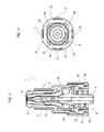
Figure 3 is an axial sectional view according to the line III-III ofFigure 2 ; -
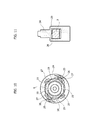
Figure 4 is a cross-sectional view according to the line IV-IV ofFigure 2 ; -
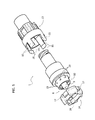
Figure 5 is an exploded view at a larger scale the connector ofFigure 1 ; -
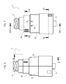
Figure 6 is a front elevation of a second embodiment of the line connector according to the invention; -
Figure 7 is a side elevation of the line connector ofFigure 6 ; -
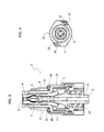
Figure 8 is an axial sectional view according to the line VIII-VIII ofFigure 7 ; -
Figure 9 is a cross-sectional view according to the line IX-IX ofFigure 7 ; -
Figure 10 is a cross-sectional view according to the line X-X ofFigure 7 ; -
Figure 11 is an axial sectional view according to the line XI-XI ofFigure 6 ; -
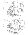
Figure 12 is an exploded perspective view from above of the line connectorFigure 7 ; and -
Figure 13 is an exploded perspective view from beneath of the line connectorFigure 7 . - The two examples of embodiment of the invention that will be described hereinafter expressly refer to a valve connector for medical infusion lines, transfusion lines, and the like of the type corresponding to the ones described and illustrated in the patent documents referred to above filed in the name of the present applicant. It should, however, be noted that the invention is likewise applicable to any medical-line connector equipped with a male connector, typically of the luer-lock type or the like, that can be coupled to a complementary female connector of a conventional type, which is also of the luer-lock type or the like, which, as is well known to the person skilled in the branch, basically consists of a tubular element provided with an end external thread.
- With initial reference to
Figures 1 to 5 , designated as a whole by 1 is a valve connector for medical lines comprising, in a way in itself known, for example from the already cited patent No.US-8,048,038 , atubular body 2 made of moulded plastic material, set coaxially within which are ahollow pin 3 and anelastic sealing member 4 having a pre-slitelastic head 5 normally set in a closing condition within aninlet end 6 of thetubular body 2, formed by a female luer-lock connector. Thehollow pin 3 forms at one end a closedterminal 7 facing theelastic head 5 and normally set at an axial distance therefrom, and at the opposite end a male luer-lock connector 8 constituted, in a way also in itself known, by an innertubular element 9 with conical outer surface in communication with thehollow pin 3 and by an internally threaded outerhollow element 10. In use, the male luer-lock connector 8 is coupled by screwing to a complementary female luer-lock connector, and then an introducer of fluid is coupled to theinlet connector 6 so as to press the sealingmember 4 axially against the action of a hollowelastic element 11 formed integrally therewith, towards theterminal 7 so as to get thepre-slit head 5 to assume an elastically deformed condition of opening and thus enable passage of fluid from the introducer to the male luer-lock connector 8. - According to the peculiar characteristic of the invention, the line connector further comprises an outer manoeuvring sleeve, designated as a whole by 12, which is coupled in unidirectional rotation to the
body 2 in the direction corresponding to screwing of the male luer-lock connector 8 to the complementary female luer-lock connector, and is free to turn in the opposite direction. - The
outer sleeve 12 extends axially, starting from the female luer-lock connector 6, until it covers entirely the outerhollow element 10 of the male luer-lock connector 8 and, in the case described herein with reference toFigures 1 and5 , it is formed by twoaxial portions axial portion 13 has a series of elastically sprungend legs 15 formed withrespective engagement teeth 16, and theportion 14 consists of a ring that surrounds the outerhollow element 10 of the male luer-lock connector 8 and is formed externally withpawling parts 17 for snap-action engagement of theteeth 16 when the twoparts body 2. - The ring that constitutes the
portion 14 is moreover formed internally with a ring of elastically sprung teeth 18 (more clearly visible inFigure 4 ), with which a ring ofteeth 19 formed on the outside of thehollow element 10 of the male luer-lock connector 8 co-operates. The arrangement of theteeth outer sleeve 12 formed by theportions body 2 of the line connector only in the direction corresponding to screwing of the male luer-lock connector 8. In the opposite direction, theteeth 18 of theportion 14 jump elastically on theteeth 19 of thehollow element 10, thus enabling free rotation of theouter sleeve 12 with respect to thebody 2 of theline connector 1. In this way, once the male luer-lock connector 8 is coupled by screwing to the complementary female luer-lock connector, it is prevented from unscrewing. - The variant illustrated in
Figures 6 to 13 , in which parts that are identical or similar to the ones already described previously are designated by the same reference numbers, differs from the first embodiment basically as regards two aspects: the outer manoeuvring sleeve, designated as a whole by 22, is formed by two radial half-shells body 2 of theline connector 1 in an axially slidable way between a first position, in which thesleeve 22 is coupled in unidirectional rotation to thebody 2 of theline connector 1 in the direction corresponding to screwing of the male luer-lock connector 8 to the complementary female luer-lock connector, and a second position in which saidsleeve 22 is coupled in rotation to thebody 2 in the opposite direction, i.e., in the direction corresponding to unscrewing of the male luer-lock connector 9. - In detail, the two half-
shells 23, 24 (which have an identical shape and can hence be obtained with a single die) also extend practically throughout the axial extension of thebody 2 of the line connector starting from the female luer-lock connector 6 so as to gird at the bottom the entire outerhollow element 10 of the male luer-lock connector 8. The two half-shells legs 25 designed to engage by snap action withincorresponding openings 26 to form thesleeve 22, and each of them is moreover formed internally with respective elastically sprungteeth 27, altogether similar to theteeth 18 of the previous embodiment, which are designed to cooperate in the same way with the ring ofexternal teeth 19 of the outerhollow element 10 of the male luer-lock connector 8. In other words, theteeth 27 couple thesleeve 22 torsionally to thebody 2 of theline connector 1 in the direction corresponding to screwing of the luer-lock connector 8, whilst rotation of thesleeve 22 with respect to thebody 2 is free in the opposite direction thanks to that theteeth 27 jump on theteeth 19. - As anticipated previously, the
sleeve 22 is moreover displaceable axially with respect to thebody 2 for a limited travel, starting from the position in which theteeth 27 are set axially in a position corresponding to theteeth 19, towards an unstable position in which engagement between theteeth 27 and theteeth 19 is no longer possible whilst thesleeve 22 couples torsionally to thebody 2 of theline connector 1 in the direction corresponding to unscrewing of the male luer-lock connector 8 from the complementary female luer-lock connector. Said torsional coupling is implemented, in the second axial position, as a result of engagement between further rings ofexternal teeth 28 andinternal teeth 29, respectively, of thebody 2 and of the half-shells sleeve 22. Theteeth Figure 11 . - As has been said, the second position corresponding to engagement between the
teeth appendages 30 formed integrally with the respective half-shells corresponding recesses 31 of thebody 2 of theline connector 1. When thesleeve 22 shifted in the second axial position is released, thesprung appendages 30 bring it back into the first position, thus obtaining disengagement between theteeth teeth - As already pointed out previously, the invention is advantageously applicable not only to the
valve connector 1 represented in the drawings but to any medical connector equipped with a male connector of the luer-lock type or similar types, which have a tubular element with conical outer surface that can engage with a female connector of a similar type (hence not necessarily a luer-lock connector). Obviously, also the other end of the line connector, i.e., the one opposite to the male connector, may be of any kind, for example formed by a simple duct applied even permanently to the body of the line connector. - Of course, the details of construction and the embodiments may vary widely with respect to what has been described and illustrated herein, without thereby departing from the scope of the present invention as defined in the ensuing claims.
- In particular, the male connector of the line connector, instead of being of the luer-lock type, may be of any different type equipped with an inner tubular element with conical outer surface. Moreover, the union between the two
axial portions shells
Claims (11)
- A connector (1) for medical infusion lines, transfusion lines, and the like, comprising a tubular body (2) having at one end a male connector (8) including an inner tubular element (9) and an outer hollow element (10), which is internally threaded and can be coupled by screwing to a complementary female connector, and further including an outer manoeuvring sleeve (12; 22) coupled in unidirectional rotation to the body (2) of the connector (1) in the direction corresponding to screwing of said male connector (8) with respect to said complementary female connector, said connector (1) being characterized in that said outer manoeuvring sleeve (12; 22) is free to turn in the opposite direction and is formed by two parts (13, 14; 23, 24) coupled together on said body (2) of the connector (1).
- The connector according to Claim 1, characterized in that said two parts (13, 14; 23, 24) are joined together via snap-fit coupling (15, 16, 17; 25, 26).
- The connector according to Claim 1, characterized in that said outer hollow element (10) of the male connector (8) has an outer ring gear (19), which co-operates with a ring of unidirectional pawling teeth (18; 27) provided inside said outer sleeve (12; 22).
- The connector according to Claim 1, characterized in that said outer sleeve (12; 22) covers entirely the internally threaded outer hollow element (10) of the male connector (8).
- The connector according to Claim 1 or Claim 2, characterized in that said outer sleeve (12) includes two axial portions (13, 14).
- The connector according to Claim 1 or Claim 2, characterized in that said outer sleeve (22) includes two radial half-shells (23, 24).
- The connector according to Claim 6, characterized in that said tubular body (2) and said outer sleeve (22) are mutually displaceable axially between a first position in which they are coupled together in unidirectional rotation in said direction of screwing of said male connector (8) and a second position, and in that in said second position means of mutual torsional coupling (28, 29) couple in rotation said sleeve (22) and said tubular body (2) in the direction corresponding to unscrewing of said male connector (8).
- The connector according to Claim 7, characterized in that it further includes elastic return means (30), which tend to keep said outer sleeve (22) and said body (2) normally in said first position.
- The connector according to Claim 8, characterized in that said elastic return means are formed by sprung appendages (30) of said sleeve (22).
- The connector according to Claim 7 or Claim 8, characterized in that it is constituted by a valve connector (1).
- The connector according to Claim 10, characterized in that said tubular body (2) has, at the end opposite to said male connector (8), an inlet (6) for insertion of an introducer of fluid and in that coaxially set within the cavity of the tubular body (2) is a hollow pin (3) having a closed terminal (7) facing said inlet (6) and axially set at a distance from the latter, said hollow pin (3) being in communication with said inner tubular element (9) of the male connector (8); there being set between said tubular body (2) and said hollow pin (3) an intermediate sealing member (4) including a pre-slit elastic head (5) normally set in a condition of closing said inlet (6) and displaceable axially towards said closed terminal (7) of said hollow pin (3), as a result of insertion of said introducer of fluid within said inlet (6), to assume an elastically deformed condition of opening, and said sealing member (4) moreover forming an elastic means (11) tending to keep said head (5) in said closing condition.
Priority Applications (1)
| Application Number | Priority Date | Filing Date | Title |
|---|---|---|---|
| PL13150798T PL2620178T3 (en) | 2012-01-24 | 2013-01-10 | Connector for medical lines |
Applications Claiming Priority (1)
| Application Number | Priority Date | Filing Date | Title |
|---|---|---|---|
| IT000056A ITTO20120056A1 (en) | 2012-01-24 | 2012-01-24 | CONNECTOR FOR MEDICAL LINES OF INFUSION, TRANSFUSION AND THE LIKE |
Publications (2)
| Publication Number | Publication Date |
|---|---|
| EP2620178A1 true EP2620178A1 (en) | 2013-07-31 |
| EP2620178B1 EP2620178B1 (en) | 2014-06-18 |
Family
ID=46001414
Family Applications (1)
| Application Number | Title | Priority Date | Filing Date |
|---|---|---|---|
| EP13150798.0A Active EP2620178B1 (en) | 2012-01-24 | 2013-01-10 | Connector for medical lines |
Country Status (13)
| Country | Link |
|---|---|
| US (1) | US8968271B2 (en) |
| EP (1) | EP2620178B1 (en) |
| JP (1) | JP6205136B2 (en) |
| CN (1) | CN103212152B (en) |
| AU (1) | AU2013200289B2 (en) |
| BR (1) | BR102013001843B1 (en) |
| CA (1) | CA2801798C (en) |
| ES (1) | ES2508191T3 (en) |
| IT (1) | ITTO20120056A1 (en) |
| MX (1) | MX2013000566A (en) |
| PL (1) | PL2620178T3 (en) |
| PT (1) | PT2620178E (en) |
| ZA (1) | ZA201300386B (en) |
Cited By (4)
| Publication number | Priority date | Publication date | Assignee | Title |
|---|---|---|---|---|
| WO2016012834A1 (en) * | 2014-07-21 | 2016-01-28 | Industrie Borla S.P.A. | Safety cap for medical devices |
| WO2018210498A1 (en) * | 2017-05-18 | 2018-11-22 | Fresenius Kabi Deutschland Gmbh | Non-releasable connector device |
| EP3777936A1 (en) * | 2019-08-13 | 2021-02-17 | Gambro Lundia AB | Non-removable connection system |
| EP4285984A4 (en) * | 2021-02-01 | 2024-12-11 | JMS Co., Ltd. | MEDICAL CONNECTOR |
Families Citing this family (43)
| Publication number | Priority date | Publication date | Assignee | Title |
|---|---|---|---|---|
| US9168366B2 (en) | 2008-12-19 | 2015-10-27 | Icu Medical, Inc. | Medical connector with closeable luer connector |
| US8323249B2 (en) | 2009-08-14 | 2012-12-04 | The Regents Of The University Of Michigan | Integrated vascular delivery system |
| WO2011146769A2 (en) | 2010-05-19 | 2011-11-24 | Tangent Medical Technologies Llc | Integrated vascular delivery system |
| US8814833B2 (en) | 2010-05-19 | 2014-08-26 | Tangent Medical Technologies Llc | Safety needle system operable with a medical device |
| EP3381505B1 (en) | 2011-09-09 | 2020-05-27 | ICU Medical, Inc. | Medical connectors with fluid-resistant mating interfaces |
| CA2891255C (en) | 2012-11-12 | 2022-10-04 | Icu Medical, Inc. | Medical connector |
| US10006573B2 (en) | 2013-02-20 | 2018-06-26 | Fisher & Paykel Healthcare Limited | Connector for multiple sized connections |
| CN105163796B (en) | 2013-03-15 | 2018-06-01 | Icu医学有限公司 | Medical connector |
| MX2015015783A (en) * | 2013-05-14 | 2016-03-07 | Fluidmaster | Click-seal torque limiting connector. |
| AU2014364218B2 (en) | 2013-12-11 | 2019-06-06 | Icu Medical, Inc. | Check valve |
| EP3102258A4 (en) | 2014-02-04 | 2017-12-27 | ICU Medical, Inc. | Self-priming systems and methods |
| ES2795328T3 (en) * | 2014-04-21 | 2020-11-23 | Becton Dickinson & Co Ltd | Fluid transfer device and its envelope |
| AU2015249872B2 (en) | 2014-04-21 | 2017-01-12 | Becton Dickinson and Company Limited | Syringe adapter with compound motion disengagement |
| ES2792512T3 (en) | 2014-04-21 | 2020-11-11 | Becton Dickinson & Co Ltd | Fluid transfer device and packaging for it |
| SG11201608968YA (en) * | 2014-05-12 | 2016-11-29 | Borla Ind | Tubular fitting for medical fluid lines |
| US11602607B2 (en) * | 2014-09-24 | 2023-03-14 | Fisher & Paykel Healthcare Limited | Swivel connector |
| US10071234B2 (en) * | 2014-11-25 | 2018-09-11 | Avent, Inc. | Dual material Y-connector |
| USD786427S1 (en) | 2014-12-03 | 2017-05-09 | Icu Medical, Inc. | Fluid manifold |
| USD793551S1 (en) | 2014-12-03 | 2017-08-01 | Icu Medical, Inc. | Fluid manifold |
| AU367143S (en) * | 2015-08-05 | 2016-02-15 | Borla Ind | Valved connector for medical lines |
| US10201693B2 (en) * | 2015-08-06 | 2019-02-12 | Hsi-Chin Tsai | Closed male luer |
| JP6756153B2 (en) * | 2016-05-23 | 2020-09-16 | ニプロ株式会社 | Medical connector |
| EP3484574A1 (en) * | 2016-10-12 | 2019-05-22 | Fresenius Medical Care Holdings, Inc. | Medical fluid line connector |
| USD843567S1 (en) * | 2016-11-07 | 2019-03-19 | Ide Tecnologia S.A De C.V. | Dialysis device connector without threads |
| USD849938S1 (en) * | 2016-11-07 | 2019-05-28 | Ide Tecnologia S.A. De C.V. | Dialysis device connector |
| USD851243S1 (en) * | 2016-11-07 | 2019-06-11 | Ide Technologies S.A. De C.V. | Dialysis device connector with threads |
| USD845474S1 (en) * | 2016-11-07 | 2019-04-09 | Ide Tecnologia S.A. De C.V. | Dialysis device connector |
| USD835268S1 (en) * | 2017-04-06 | 2018-12-04 | Becton, Dickinson And Company | Syringe tip with indicator |
| USD835269S1 (en) * | 2017-04-06 | 2018-12-04 | Becton, Dickinson And Company | Syringe tip with indicator |
| US10857343B2 (en) | 2017-04-06 | 2020-12-08 | Becton, Dickinson And Company | Medical devices with visual and tactile indicators |
| US9925365B1 (en) * | 2017-06-21 | 2018-03-27 | Rymed Technologies, Llc | Needleless IV injection port |
| WO2019130891A1 (en) * | 2017-12-26 | 2019-07-04 | テルモ株式会社 | Medical connector |
| CN109224285B (en) * | 2018-07-12 | 2021-03-05 | 合肥市第二人民医院 | Negative pressure drainage tube connecting device |
| CN108785848B (en) * | 2018-09-07 | 2023-11-21 | 临沂市兴华医用器材有限公司 | Anesthesia catheter connector |
| US12208064B2 (en) | 2020-04-30 | 2025-01-28 | Avent, Inc. | Polyurethane bonding skeleton for feeding tube device |
| AU2021419942B2 (en) * | 2021-01-14 | 2025-04-24 | Daiwa Can Company | Connector |
| US12636481B2 (en) | 2021-08-03 | 2026-05-26 | Icu Medical, Inc. | Medical connectors |
| US20250127994A1 (en) * | 2021-09-24 | 2025-04-24 | Sanofi | Encoder Ring, Dose Recording System and Drug Delivery Device Herewith |
| JP7890876B2 (en) * | 2022-07-07 | 2026-07-15 | テルモ株式会社 | Medical connectors |
| JP2025536713A (en) * | 2022-11-17 | 2025-11-07 | アイシーユー・メディカル・インコーポレーテッド | Medical Connectors |
| CN116421315B (en) * | 2023-06-14 | 2023-09-05 | 中南大学 | Connecting device and operation navigation system |
| USD1105422S1 (en) | 2024-02-09 | 2025-12-09 | Icu Medical, Inc. | Medical connector cover |
| US20250360300A1 (en) * | 2024-05-22 | 2025-11-27 | Becton Dickinson And Company | Non-Disconnectable Luer Lock |
Citations (9)
| Publication number | Priority date | Publication date | Assignee | Title |
|---|---|---|---|---|
| US5702374A (en) | 1995-11-14 | 1997-12-30 | Abbott Laboratories | Male luer connector assembly |
| US6217564B1 (en) * | 1994-02-17 | 2001-04-17 | Clinical Product Development Limited | Couplings for medical cannulae |
| WO2006013433A1 (en) * | 2004-07-27 | 2006-02-09 | Industrie Borla S.P.A. | Valve connector for medical infusion lines |
| EP1747797A1 (en) | 2005-07-25 | 2007-01-31 | Industrie Borla SpA | Medical connector having ratchet means |
| US20080172039A1 (en) | 2006-10-02 | 2008-07-17 | B. Braun Medical Inc. | Ratcheting luer lock connector |
| US20090292274A1 (en) | 2008-05-21 | 2009-11-26 | Industrie Borla S.P.A. | Valve connector for medical lines |
| WO2010071812A1 (en) * | 2008-12-19 | 2010-06-24 | Baxter International Inc. | Catheter/fistula needle to bloodline connection assurance device |
| US8048038B2 (en) | 2006-03-17 | 2011-11-01 | Industrie Borla S.P.A. | Valve connector for medical lines |
| WO2012002316A1 (en) * | 2010-06-30 | 2012-01-05 | テルモ株式会社 | Connector and connector assembly |
Family Cites Families (16)
| Publication number | Priority date | Publication date | Assignee | Title |
|---|---|---|---|---|
| US4432759A (en) * | 1982-04-26 | 1984-02-21 | Abbott Laboratories | Connecting device for medical liquid containers |
| HU210921B (en) * | 1990-03-28 | 1995-09-28 | Chinoin Gyogyszer Es Vegyeszet | Process for preparing inclusion complexes of n-ethoxycarbonyl-3-morpholino-sydnonimine formed with cyclodextrines and pharmaceutical compositions containing them |
| US5197895A (en) * | 1991-05-10 | 1993-03-30 | Bicore Monitoring Systems | Disposable electro-fluidic connector with data storage |
| GB9801261D0 (en) * | 1998-01-21 | 1998-03-18 | Peters Joseph L | Couplings for medical cannulae |
| JP2001187990A (en) * | 1999-12-28 | 2001-07-10 | Ookisu:Kk | Medical connection members |
| US6722705B2 (en) * | 2002-04-25 | 2004-04-20 | Ab Korkor Medical, Inc. | Medical tubing connector |
| JP2005296140A (en) * | 2004-04-07 | 2005-10-27 | Jms Co Ltd | Syringe with connector and connector |
| EP1733749A4 (en) * | 2004-04-07 | 2013-09-04 | Jms Co Ltd | Syringe with connector, connector for syringe, and syringe |
| US7497484B2 (en) * | 2004-08-11 | 2009-03-03 | Smiths Medical Asd, Inc. | Medical coupling system |
| US8932208B2 (en) * | 2005-05-26 | 2015-01-13 | Maquet Cardiovascular Llc | Apparatus and methods for performing minimally-invasive surgical procedures |
| US7998134B2 (en) * | 2007-05-16 | 2011-08-16 | Icu Medical, Inc. | Medical connector |
| US8852167B2 (en) * | 2005-12-01 | 2014-10-07 | Bayer Medical Care Inc. | Medical connector |
| US8523830B2 (en) * | 2007-01-16 | 2013-09-03 | Catheter Connections | Disinfecting caps for medical female luer connectors |
| US7926856B2 (en) * | 2007-03-02 | 2011-04-19 | Smith & Nephew, Inc. | Fluid conduit connection |
| EP2589407B1 (en) * | 2007-03-02 | 2017-07-12 | Covidien LP | Catheter system with attachable catheter hub |
| US8414542B2 (en) * | 2008-03-04 | 2013-04-09 | Infusion Innovations, Inc. | Devices, assemblies, and methods for controlling fluid flow |
-
2012
- 2012-01-24 IT IT000056A patent/ITTO20120056A1/en unknown
-
2013
- 2013-01-10 PT PT131507980T patent/PT2620178E/en unknown
- 2013-01-10 EP EP13150798.0A patent/EP2620178B1/en active Active
- 2013-01-10 ES ES13150798.0T patent/ES2508191T3/en active Active
- 2013-01-10 PL PL13150798T patent/PL2620178T3/en unknown
- 2013-01-11 US US13/739,586 patent/US8968271B2/en active Active
- 2013-01-14 CA CA2801798A patent/CA2801798C/en active Active
- 2013-01-15 MX MX2013000566A patent/MX2013000566A/en active IP Right Grant
- 2013-01-15 ZA ZA2013/00386A patent/ZA201300386B/en unknown
- 2013-01-16 AU AU2013200289A patent/AU2013200289B2/en active Active
- 2013-01-24 JP JP2013011367A patent/JP6205136B2/en active Active
- 2013-01-24 BR BR102013001843-0A patent/BR102013001843B1/en active IP Right Grant
- 2013-01-24 CN CN201310026699.4A patent/CN103212152B/en active Active
Patent Citations (10)
| Publication number | Priority date | Publication date | Assignee | Title |
|---|---|---|---|---|
| US6217564B1 (en) * | 1994-02-17 | 2001-04-17 | Clinical Product Development Limited | Couplings for medical cannulae |
| US5702374A (en) | 1995-11-14 | 1997-12-30 | Abbott Laboratories | Male luer connector assembly |
| WO2006013433A1 (en) * | 2004-07-27 | 2006-02-09 | Industrie Borla S.P.A. | Valve connector for medical infusion lines |
| US7784766B2 (en) | 2004-07-27 | 2010-08-31 | Industrie Borla S.P.A. | Valve connector for medical infusion lines |
| EP1747797A1 (en) | 2005-07-25 | 2007-01-31 | Industrie Borla SpA | Medical connector having ratchet means |
| US8048038B2 (en) | 2006-03-17 | 2011-11-01 | Industrie Borla S.P.A. | Valve connector for medical lines |
| US20080172039A1 (en) | 2006-10-02 | 2008-07-17 | B. Braun Medical Inc. | Ratcheting luer lock connector |
| US20090292274A1 (en) | 2008-05-21 | 2009-11-26 | Industrie Borla S.P.A. | Valve connector for medical lines |
| WO2010071812A1 (en) * | 2008-12-19 | 2010-06-24 | Baxter International Inc. | Catheter/fistula needle to bloodline connection assurance device |
| WO2012002316A1 (en) * | 2010-06-30 | 2012-01-05 | テルモ株式会社 | Connector and connector assembly |
Cited By (9)
| Publication number | Priority date | Publication date | Assignee | Title |
|---|---|---|---|---|
| WO2016012834A1 (en) * | 2014-07-21 | 2016-01-28 | Industrie Borla S.P.A. | Safety cap for medical devices |
| US10279160B2 (en) | 2014-07-21 | 2019-05-07 | Industrie Borla S.P.A. | Safety cap for medical devices |
| AU2014401738B2 (en) * | 2014-07-21 | 2019-09-19 | Industrie Borla S.P.A. | Safety cap for medical devices |
| WO2018210498A1 (en) * | 2017-05-18 | 2018-11-22 | Fresenius Kabi Deutschland Gmbh | Non-releasable connector device |
| EP3777936A1 (en) * | 2019-08-13 | 2021-02-17 | Gambro Lundia AB | Non-removable connection system |
| WO2021028434A1 (en) * | 2019-08-13 | 2021-02-18 | Gambro Lundia Ab | Non-removable connection system |
| CN114555174A (en) * | 2019-08-13 | 2022-05-27 | 甘布罗伦迪亚股份公司 | Connection system that cannot be removed |
| EP4285984A4 (en) * | 2021-02-01 | 2024-12-11 | JMS Co., Ltd. | MEDICAL CONNECTOR |
| US12605532B2 (en) | 2021-02-01 | 2026-04-21 | Jms Co., Ltd. | Medical connector |
Also Published As
| Publication number | Publication date |
|---|---|
| US8968271B2 (en) | 2015-03-03 |
| CN103212152B (en) | 2017-04-12 |
| ES2508191T3 (en) | 2014-10-16 |
| BR102013001843A2 (en) | 2015-06-02 |
| JP2013150805A (en) | 2013-08-08 |
| ZA201300386B (en) | 2013-09-25 |
| CA2801798C (en) | 2019-11-26 |
| JP6205136B2 (en) | 2017-09-27 |
| US20130187381A1 (en) | 2013-07-25 |
| CA2801798A1 (en) | 2013-07-24 |
| EP2620178B1 (en) | 2014-06-18 |
| BR102013001843B1 (en) | 2021-03-30 |
| PL2620178T3 (en) | 2015-02-27 |
| AU2013200289B2 (en) | 2017-10-26 |
| CN103212152A (en) | 2013-07-24 |
| PT2620178E (en) | 2014-10-14 |
| MX2013000566A (en) | 2013-07-23 |
| ITTO20120056A1 (en) | 2013-07-25 |
Similar Documents
| Publication | Publication Date | Title |
|---|---|---|
| EP2620178B1 (en) | Connector for medical lines | |
| US7588563B2 (en) | Medical connector | |
| EP3004711B1 (en) | Connector for medical lines | |
| CA2713410C (en) | Valve connector for medical lines | |
| US10537726B2 (en) | Tubular fitting for medical fluid lines | |
| EP3171926B1 (en) | Safety connector for medical devices | |
| EP3047872B1 (en) | Valved male luer connector | |
| NZ605901B (en) | Connector for medical lines | |
| EP3439713B1 (en) | Pressure pod for haemodialysis medical lines |
Legal Events
| Date | Code | Title | Description |
|---|---|---|---|
| PUAI | Public reference made under article 153(3) epc to a published international application that has entered the european phase |
Free format text: ORIGINAL CODE: 0009012 |
|
| AK | Designated contracting states |
Kind code of ref document: A1 Designated state(s): AL AT BE BG CH CY CZ DE DK EE ES FI FR GB GR HR HU IE IS IT LI LT LU LV MC MK MT NL NO PL PT RO RS SE SI SK SM TR |
|
| AX | Request for extension of the european patent |
Extension state: BA ME |
|
| 17P | Request for examination filed |
Effective date: 20131129 |
|
| GRAP | Despatch of communication of intention to grant a patent |
Free format text: ORIGINAL CODE: EPIDOSNIGR1 |
|
| RBV | Designated contracting states (corrected) |
Designated state(s): AL AT BE BG CH CY CZ DE DK EE ES FI FR GB GR HR HU IE IS IT LI LT LU LV MC MK MT NL NO PL PT RO RS SE SI SK SM TR |
|
| INTG | Intention to grant announced |
Effective date: 20140109 |
|
| GRAS | Grant fee paid |
Free format text: ORIGINAL CODE: EPIDOSNIGR3 |
|
| GRAA | (expected) grant |
Free format text: ORIGINAL CODE: 0009210 |
|
| AK | Designated contracting states |
Kind code of ref document: B1 Designated state(s): AL AT BE BG CH CY CZ DE DK EE ES FI FR GB GR HR HU IE IS IT LI LT LU LV MC MK MT NL NO PL PT RO RS SE SI SK SM TR |
|
| REG | Reference to a national code |
Ref country code: GB Ref legal event code: FG4D |
|
| REG | Reference to a national code |
Ref country code: CH Ref legal event code: EP |
|
| REG | Reference to a national code |
Ref country code: AT Ref legal event code: REF Ref document number: 672975 Country of ref document: AT Kind code of ref document: T Effective date: 20140715 |
|
| REG | Reference to a national code |
Ref country code: IE Ref legal event code: FG4D |
|
| REG | Reference to a national code |
Ref country code: DE Ref legal event code: R096 Ref document number: 602013000075 Country of ref document: DE Effective date: 20140731 |
|
| REG | Reference to a national code |
Ref country code: RO Ref legal event code: EPE |
|
| REG | Reference to a national code |
Ref country code: DE Ref legal event code: R082 Ref document number: 602013000075 Country of ref document: DE Representative=s name: GULDE & PARTNER PATENT- UND RECHTSANWALTSKANZL, DE |
|
| REG | Reference to a national code |
Ref country code: SE Ref legal event code: TRGR |
|
| REG | Reference to a national code |
Ref country code: PT Ref legal event code: SC4A Free format text: AVAILABILITY OF NATIONAL TRANSLATION Effective date: 20141007 |
|
| REG | Reference to a national code |
Ref country code: NL Ref legal event code: T3 |
|
| REG | Reference to a national code |
Ref country code: ES Ref legal event code: FG2A Ref document number: 2508191 Country of ref document: ES Kind code of ref document: T3 Effective date: 20141016 |
|
| PG25 | Lapsed in a contracting state [announced via postgrant information from national office to epo] |
Ref country code: NO Free format text: LAPSE BECAUSE OF FAILURE TO SUBMIT A TRANSLATION OF THE DESCRIPTION OR TO PAY THE FEE WITHIN THE PRESCRIBED TIME-LIMIT Effective date: 20140918 Ref country code: LT Free format text: LAPSE BECAUSE OF FAILURE TO SUBMIT A TRANSLATION OF THE DESCRIPTION OR TO PAY THE FEE WITHIN THE PRESCRIBED TIME-LIMIT Effective date: 20140618 Ref country code: CY Free format text: LAPSE BECAUSE OF FAILURE TO SUBMIT A TRANSLATION OF THE DESCRIPTION OR TO PAY THE FEE WITHIN THE PRESCRIBED TIME-LIMIT Effective date: 20140618 Ref country code: FI Free format text: LAPSE BECAUSE OF FAILURE TO SUBMIT A TRANSLATION OF THE DESCRIPTION OR TO PAY THE FEE WITHIN THE PRESCRIBED TIME-LIMIT Effective date: 20140618 |
|
| REG | Reference to a national code |
Ref country code: AT Ref legal event code: MK05 Ref document number: 672975 Country of ref document: AT Kind code of ref document: T Effective date: 20140618 |
|
| REG | Reference to a national code |
Ref country code: LT Ref legal event code: MG4D |
|
| REG | Reference to a national code |
Ref country code: GR Ref legal event code: EP Ref document number: 20140401883 Country of ref document: GR Effective date: 20141017 |
|
| PG25 | Lapsed in a contracting state [announced via postgrant information from national office to epo] |
Ref country code: HR Free format text: LAPSE BECAUSE OF FAILURE TO SUBMIT A TRANSLATION OF THE DESCRIPTION OR TO PAY THE FEE WITHIN THE PRESCRIBED TIME-LIMIT Effective date: 20140618 Ref country code: LV Free format text: LAPSE BECAUSE OF FAILURE TO SUBMIT A TRANSLATION OF THE DESCRIPTION OR TO PAY THE FEE WITHIN THE PRESCRIBED TIME-LIMIT Effective date: 20140618 Ref country code: RS Free format text: LAPSE BECAUSE OF FAILURE TO SUBMIT A TRANSLATION OF THE DESCRIPTION OR TO PAY THE FEE WITHIN THE PRESCRIBED TIME-LIMIT Effective date: 20140618 |
|
| PG25 | Lapsed in a contracting state [announced via postgrant information from national office to epo] |
Ref country code: EE Free format text: LAPSE BECAUSE OF FAILURE TO SUBMIT A TRANSLATION OF THE DESCRIPTION OR TO PAY THE FEE WITHIN THE PRESCRIBED TIME-LIMIT Effective date: 20140618 Ref country code: SK Free format text: LAPSE BECAUSE OF FAILURE TO SUBMIT A TRANSLATION OF THE DESCRIPTION OR TO PAY THE FEE WITHIN THE PRESCRIBED TIME-LIMIT Effective date: 20140618 |
|
| PG25 | Lapsed in a contracting state [announced via postgrant information from national office to epo] |
Ref country code: AT Free format text: LAPSE BECAUSE OF FAILURE TO SUBMIT A TRANSLATION OF THE DESCRIPTION OR TO PAY THE FEE WITHIN THE PRESCRIBED TIME-LIMIT Effective date: 20140618 Ref country code: IS Free format text: LAPSE BECAUSE OF FAILURE TO SUBMIT A TRANSLATION OF THE DESCRIPTION OR TO PAY THE FEE WITHIN THE PRESCRIBED TIME-LIMIT Effective date: 20141018 |
|
| REG | Reference to a national code |
Ref country code: PL Ref legal event code: T3 |
|
| REG | Reference to a national code |
Ref country code: DE Ref legal event code: R097 Ref document number: 602013000075 Country of ref document: DE |
|
| PLBE | No opposition filed within time limit |
Free format text: ORIGINAL CODE: 0009261 |
|
| STAA | Information on the status of an ep patent application or granted ep patent |
Free format text: STATUS: NO OPPOSITION FILED WITHIN TIME LIMIT |
|
| PG25 | Lapsed in a contracting state [announced via postgrant information from national office to epo] |
Ref country code: DK Free format text: LAPSE BECAUSE OF FAILURE TO SUBMIT A TRANSLATION OF THE DESCRIPTION OR TO PAY THE FEE WITHIN THE PRESCRIBED TIME-LIMIT Effective date: 20140618 |
|
| 26N | No opposition filed |
Effective date: 20150319 |
|
| PG25 | Lapsed in a contracting state [announced via postgrant information from national office to epo] |
Ref country code: SI Free format text: LAPSE BECAUSE OF FAILURE TO SUBMIT A TRANSLATION OF THE DESCRIPTION OR TO PAY THE FEE WITHIN THE PRESCRIBED TIME-LIMIT Effective date: 20140618 |
|
| PG25 | Lapsed in a contracting state [announced via postgrant information from national office to epo] |
Ref country code: LU Free format text: LAPSE BECAUSE OF FAILURE TO SUBMIT A TRANSLATION OF THE DESCRIPTION OR TO PAY THE FEE WITHIN THE PRESCRIBED TIME-LIMIT Effective date: 20150110 |
|
| REG | Reference to a national code |
Ref country code: FR Ref legal event code: PLFP Year of fee payment: 4 |
|
| REG | Reference to a national code |
Ref country code: CH Ref legal event code: PL |
|
| PG25 | Lapsed in a contracting state [announced via postgrant information from national office to epo] |
Ref country code: LI Free format text: LAPSE BECAUSE OF NON-PAYMENT OF DUE FEES Effective date: 20160131 Ref country code: CH Free format text: LAPSE BECAUSE OF NON-PAYMENT OF DUE FEES Effective date: 20160131 |
|
| PG25 | Lapsed in a contracting state [announced via postgrant information from national office to epo] |
Ref country code: MT Free format text: LAPSE BECAUSE OF FAILURE TO SUBMIT A TRANSLATION OF THE DESCRIPTION OR TO PAY THE FEE WITHIN THE PRESCRIBED TIME-LIMIT Effective date: 20140618 |
|
| REG | Reference to a national code |
Ref country code: FR Ref legal event code: PLFP Year of fee payment: 5 |
|
| PG25 | Lapsed in a contracting state [announced via postgrant information from national office to epo] |
Ref country code: BG Free format text: LAPSE BECAUSE OF FAILURE TO SUBMIT A TRANSLATION OF THE DESCRIPTION OR TO PAY THE FEE WITHIN THE PRESCRIBED TIME-LIMIT Effective date: 20140618 Ref country code: HU Free format text: LAPSE BECAUSE OF FAILURE TO SUBMIT A TRANSLATION OF THE DESCRIPTION OR TO PAY THE FEE WITHIN THE PRESCRIBED TIME-LIMIT; INVALID AB INITIO Effective date: 20130110 |
|
| REG | Reference to a national code |
Ref country code: FR Ref legal event code: PLFP Year of fee payment: 6 |
|
| PG25 | Lapsed in a contracting state [announced via postgrant information from national office to epo] |
Ref country code: SM Free format text: LAPSE BECAUSE OF FAILURE TO SUBMIT A TRANSLATION OF THE DESCRIPTION OR TO PAY THE FEE WITHIN THE PRESCRIBED TIME-LIMIT Effective date: 20140618 |
|
| PG25 | Lapsed in a contracting state [announced via postgrant information from national office to epo] |
Ref country code: MK Free format text: LAPSE BECAUSE OF FAILURE TO SUBMIT A TRANSLATION OF THE DESCRIPTION OR TO PAY THE FEE WITHIN THE PRESCRIBED TIME-LIMIT Effective date: 20140618 |
|
| PG25 | Lapsed in a contracting state [announced via postgrant information from national office to epo] |
Ref country code: AL Free format text: LAPSE BECAUSE OF FAILURE TO SUBMIT A TRANSLATION OF THE DESCRIPTION OR TO PAY THE FEE WITHIN THE PRESCRIBED TIME-LIMIT Effective date: 20140618 |
|
| P01 | Opt-out of the competence of the unified patent court (upc) registered |
Effective date: 20230614 |
|
| PGFP | Annual fee paid to national office [announced via postgrant information from national office to epo] |
Ref country code: PT Payment date: 20251222 Year of fee payment: 14 |
|
| PGFP | Annual fee paid to national office [announced via postgrant information from national office to epo] |
Ref country code: CZ Payment date: 20251230 Year of fee payment: 14 |
|
| PGFP | Annual fee paid to national office [announced via postgrant information from national office to epo] |
Ref country code: PL Payment date: 20251217 Year of fee payment: 14 |
|
| PGFP | Annual fee paid to national office [announced via postgrant information from national office to epo] |
Ref country code: NL Payment date: 20260122 Year of fee payment: 14 |
|
| PGFP | Annual fee paid to national office [announced via postgrant information from national office to epo] |
Ref country code: SE Payment date: 20260126 Year of fee payment: 14 |
|
| PGFP | Annual fee paid to national office [announced via postgrant information from national office to epo] |
Ref country code: GB Payment date: 20260126 Year of fee payment: 14 |
|
| PGFP | Annual fee paid to national office [announced via postgrant information from national office to epo] |
Ref country code: MC Payment date: 20260120 Year of fee payment: 14 Ref country code: ES Payment date: 20260210 Year of fee payment: 14 |
|
| PGFP | Annual fee paid to national office [announced via postgrant information from national office to epo] |
Ref country code: IE Payment date: 20260120 Year of fee payment: 14 Ref country code: DE Payment date: 20260127 Year of fee payment: 14 |
|
| PGFP | Annual fee paid to national office [announced via postgrant information from national office to epo] |
Ref country code: BE Payment date: 20260123 Year of fee payment: 14 Ref country code: RO Payment date: 20260108 Year of fee payment: 14 Ref country code: IT Payment date: 20260115 Year of fee payment: 14 |
|
| PGFP | Annual fee paid to national office [announced via postgrant information from national office to epo] |
Ref country code: FR Payment date: 20260126 Year of fee payment: 14 |
|
| PGFP | Annual fee paid to national office [announced via postgrant information from national office to epo] |
Ref country code: TR Payment date: 20260105 Year of fee payment: 14 |
|
| PGFP | Annual fee paid to national office [announced via postgrant information from national office to epo] |
Ref country code: GR Payment date: 20260120 Year of fee payment: 14 |