EP2620177A1 - Stossdämpfender nadelbalken für tattoomaschinen - Google Patents
Stossdämpfender nadelbalken für tattoomaschinen Download PDFInfo
- Publication number
- EP2620177A1 EP2620177A1 EP11826445.6A EP11826445A EP2620177A1 EP 2620177 A1 EP2620177 A1 EP 2620177A1 EP 11826445 A EP11826445 A EP 11826445A EP 2620177 A1 EP2620177 A1 EP 2620177A1
- Authority
- EP
- European Patent Office
- Prior art keywords
- bar
- shrinkable
- elastic element
- rigid tube
- segment
- Prior art date
- Legal status (The legal status is an assumption and is not a legal conclusion. Google has not performed a legal analysis and makes no representation as to the accuracy of the status listed.)
- Withdrawn
Links
- 238000000926 separation method Methods 0.000 claims abstract description 14
- 238000000034 method Methods 0.000 claims description 6
- 238000004519 manufacturing process Methods 0.000 claims description 5
- 238000005520 cutting process Methods 0.000 claims description 4
- 239000002654 heat shrinkable material Substances 0.000 claims description 4
- 238000010438 heat treatment Methods 0.000 claims description 4
- 210000003491 skin Anatomy 0.000 description 4
- 230000035515 penetration Effects 0.000 description 3
- 239000004033 plastic Substances 0.000 description 3
- 230000003139 buffering effect Effects 0.000 description 2
- 210000002615 epidermis Anatomy 0.000 description 2
- 230000035876 healing Effects 0.000 description 2
- 229910000831 Steel Inorganic materials 0.000 description 1
- 230000000740 bleeding effect Effects 0.000 description 1
- 239000008280 blood Substances 0.000 description 1
- 210000004369 blood Anatomy 0.000 description 1
- 210000004207 dermis Anatomy 0.000 description 1
- 239000013013 elastic material Substances 0.000 description 1
- 208000014674 injury Diseases 0.000 description 1
- 238000005304 joining Methods 0.000 description 1
- 238000012986 modification Methods 0.000 description 1
- 230000004048 modification Effects 0.000 description 1
- 239000000049 pigment Substances 0.000 description 1
- 239000010959 steel Substances 0.000 description 1
- 230000008733 trauma Effects 0.000 description 1
Images


Classifications
-
- A—HUMAN NECESSITIES
- A61—MEDICAL OR VETERINARY SCIENCE; HYGIENE
- A61M—DEVICES FOR INTRODUCING MEDIA INTO, OR ONTO, THE BODY; DEVICES FOR TRANSDUCING BODY MEDIA OR FOR TAKING MEDIA FROM THE BODY; DEVICES FOR PRODUCING OR ENDING SLEEP OR STUPOR
- A61M37/00—Other apparatus for introducing media into the body; Percutany, i.e. introducing medicines into the body by diffusion through the skin
- A61M37/0076—Tattooing apparatus
Definitions
- the invention is related to a needle-holding bar for a tattoing machine, to a method of manufacturing such a bar and to a method of tattooing.
- Tattooing machines are portable devices equipped with a needle having a reciprocating motion that enters and exits the skin and inserts pigments (for example, indelible ink) underneath the epidermis.
- a needle or needles (there may be several), is mounted on holding a bar the other end of which has a hook shape and is engaged to the reciprocating motion mechanism.
- the bars are made of steel, and consequently are not very flexible, and sometimes they drive the needle too deeply underneath the skin, drawing blood, which, besides being painful, complicates the making of the tattoo and impairs its quality.
- the needle-holding bar comprises two separated but substantially aligned bar segments, an elastic element arranged longitudinally between the two segments, a rigid tube that houses the elastic element and receives a portion of each segment in its interior, and a shrinkable sleeve that covers the tube and a portion of each segment and joins these three elements.
- the elastic element interposed in the bar provides a buffering system that actuates on the incidence of the needle at the skin, limiting and softening the penetration of the needle in the layers of the skin, the dermis and epidermis. This improves the ink penetration and accelerates the healing, causing less pain in the process as there is less trauma.
- the rigid tube serves for keeping the two segments of the bar aligned along its axial direction, and the shrinkable sleeve serves to hold all the pieces longitudinally in place and keep the bar from being divided.
- the elastic element is separated from each bar segment, thus allowing the top bar segment, which receives the reciprocating motion, a certain degree of unproductive linear motion before the elastic element provides the buffering.
- the elastic element is substantially cylindrical, the concept of "cylinder” being understood to include different cross-sectional shapes, such as a circle or square.
- the elastic element is preferably made of rubber, which is the most common and cheap elastic material.
- the rigid tube is preferably made of PVC, which is a commonly used cheap and rigid plastic.
- the shrinkable sleeve is a rubber element, although it is preferably made of a heat-shrinkable material.
- the bar comprises a shrinkable sheath arranged on one of the bar segments and a shrinkable sheath arranged on the other bar segment, the separation between each shrinkable sheath and each end of rigid tube being longer than the possible separation between each segment and the elastic element.
- These sheaths serve as an abutment for each bar segment against the rigid tube, so that the elastic element does not become too compressed.
- the shrinkable sleeve covers the rigid tube and a portion of each shrinkable sheath, joining them to said tube to hold all the pieces in place longitudinally and to keep the bar from becoming divided.
- the shrinkable sheath is made of a heat-shrinkable material.
- a method of manufacturing the needle-holding bar of the invention comprises the steps of:
- a small separation is left inside the rigid tube between each bar segment and the elastic element in order to avoid the risk of the elastic element becoming permanently compressed or compressed more than it should.
- a method of manufacturing the needle-holding bar of the invention comprises the steps of:
- a separation is left between each bar segment and the elastic element inside the rigid tube, and a longer separation is left between each heat-shrinkable sheath and the rigid tube, so that the sheaths serve as an abutment.
- a method for tattooing employs the needle-holding bar of the invention.
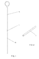
- Figure 1 shows a conventional bar cut into two pieces or segments 1A and 1 B, with a cylindrical rubber element 3 between them.
- Figure 2 shows a rigid plastic tube 2 into which the rubber element 3 and the segments 1A and 1 B are introduced, as shown in figure 3 , said elements being aligned and the rubber element being placed between them.
- the rigid tube 2 prevents the bar from flexing laterally but allows the axial motion of the two bar segments.
- Figure 4 shows the bar of figure 3 covered with heat-shrinkable plastic sleeve 4, which when heated shrinks on the segments 1A and 1 B and the tube 2 (the sleeve 4 may be, for example, a shrinkable rubber element), leaving them joined in order to hold them in place longitudinally (that is, in the axial direction), while having a certain longitudinal flexibility.
- the sleeve 4 may be, for example, a shrinkable rubber element
- Segments 1A and 1 B may have a small relative longitudinal motion (of entry and exit of tube 4, compressing the rubber element 3 or separating themselves from it), but the shrinkable sheath keeps them joined together once it has been shrunk.
- Figure 5 is like figure 4 but only with visible lines (the dotted lines in the other figures represent unseen lines).
- a shrinkable strip for example, heat shrinkable
- 5A and 5B are applied on each segment of bar 1A and 1 B, as shown in figures 6 and 7 .
- these strips constitute sheaths that act as abutments for the entry motion of the segments 1A and 1 B into the tube 2, which prevents the rubber element 3 from being excessively compressed.
- the separation between each sheath 5A and 5B, and the tube 2 is greater than the separation between each segment 1A and 1 B and the rubber element 3 (which could be null).
- the shrinkable sleeve 4 is also applied on the bar having the shrinkable sheaths 5A and 5B, in this case covering the tube 2 and said shrinkable sheaths for the same purpose of keeping the assembly joined together ( figure 8 ).
- Figure 9 is like figure 8 but with the lines visible.
- the bar segments 1 A and 1 B may have a length of approximately 5.5 cm and a diameter of approximately 1.5 mm; the rigid tube 2 a length of approximately 4 cm and a diameter of approximately 2 mm; the rubber cylinder 3 a length of approximately 0.5 cm and a diameter of approximately 1.5 mm; the shrinkable sheaths 5A and 5B a length of approximately 3 cm and a diameter of approximately 2 mm; and the shrinkable sleeve 4 a length of approximately 6.5 cm and a diameter of approximately 2.5 mm.
Landscapes
- Health & Medical Sciences (AREA)
- Engineering & Computer Science (AREA)
- Hematology (AREA)
- Life Sciences & Earth Sciences (AREA)
- Medical Informatics (AREA)
- Anesthesiology (AREA)
- Biomedical Technology (AREA)
- Heart & Thoracic Surgery (AREA)
- Veterinary Medicine (AREA)
- Dermatology (AREA)
- Animal Behavior & Ethology (AREA)
- General Health & Medical Sciences (AREA)
- Public Health (AREA)
- Virology (AREA)
- Infusion, Injection, And Reservoir Apparatuses (AREA)
- Coating Apparatus (AREA)
Applications Claiming Priority (2)
| Application Number | Priority Date | Filing Date | Title |
|---|---|---|---|
| ES201001237A ES2394477B1 (es) | 2010-09-21 | 2010-09-21 | Varilla amortiguadora porta agujas para maquinas de tatuajes |
| PCT/ES2011/070653 WO2012038571A1 (es) | 2010-09-21 | 2011-09-19 | Varilla amortiguadora porta-agujas para máquinas de tatuajes. |
Publications (1)
| Publication Number | Publication Date |
|---|---|
| EP2620177A1 true EP2620177A1 (de) | 2013-07-31 |
Family
ID=45873481
Family Applications (1)
| Application Number | Title | Priority Date | Filing Date |
|---|---|---|---|
| EP11826445.6A Withdrawn EP2620177A1 (de) | 2010-09-21 | 2011-09-19 | Stossdämpfender nadelbalken für tattoomaschinen |
Country Status (3)
| Country | Link |
|---|---|
| EP (1) | EP2620177A1 (de) |
| ES (1) | ES2394477B1 (de) |
| WO (1) | WO2012038571A1 (de) |
Families Citing this family (3)
| Publication number | Priority date | Publication date | Assignee | Title |
|---|---|---|---|---|
| ES2541334B1 (es) * | 2013-12-17 | 2016-04-25 | Richard BONATTI ANDRADA | Varilla porta-agujas para una máquina de tatuar |
| JP5980355B2 (ja) | 2015-01-30 | 2016-08-31 | 大王製紙株式会社 | 吸収性物品の伸縮構造、及びこれを用いたパンツタイプ使い捨ておむつ |
| US20220193387A1 (en) * | 2020-12-18 | 2022-06-23 | Joseph B. Clark | Ergonomic Tattoo Cartridge |
Family Cites Families (5)
| Publication number | Priority date | Publication date | Assignee | Title |
|---|---|---|---|---|
| US5472449A (en) * | 1993-07-26 | 1995-12-05 | Chou; Kuei C. | Permanent pigment applicator having a detachable needle coupler |
| GB2359048B (en) * | 2000-02-10 | 2004-01-21 | Horton Neville Guy | Tattooing device |
| FR2825028B1 (fr) * | 2001-05-28 | 2004-04-30 | Sylvie Patricia Claudin Merkel | Ensemble, sterile a usage unique, buse avec tige porte aiguilles et aiguilles pour tatouage et dermopigmentation |
| PL1618915T3 (pl) * | 2004-07-21 | 2007-06-29 | Mt Derm Gmbh | Przyrząd do miejscowego nakłuwania skóry |
| US20070060937A1 (en) * | 2005-08-30 | 2007-03-15 | Liu Chen H | Safety needle holder |
-
2010
- 2010-09-21 ES ES201001237A patent/ES2394477B1/es active Active
-
2011
- 2011-09-19 EP EP11826445.6A patent/EP2620177A1/de not_active Withdrawn
- 2011-09-19 WO PCT/ES2011/070653 patent/WO2012038571A1/es not_active Ceased
Non-Patent Citations (1)
| Title |
|---|
| See references of WO2012038571A1 * |
Also Published As
| Publication number | Publication date |
|---|---|
| WO2012038571A1 (es) | 2012-03-29 |
| ES2394477A1 (es) | 2013-02-01 |
| WO2012038571A4 (es) | 2012-06-07 |
| ES2394477B1 (es) | 2013-12-09 |
Similar Documents
| Publication | Publication Date | Title |
|---|---|---|
| EP2620177A1 (de) | Stossdämpfender nadelbalken für tattoomaschinen | |
| US20070135681A1 (en) | Flexible needle | |
| KR101472943B1 (ko) | 피부 주름 성형용 캐뉼라 및 그 제조 방법 | |
| US8479625B2 (en) | Method to manufacture a tube sump with integral clips | |
| US20080281338A1 (en) | Surgical Suture System | |
| US20160345648A1 (en) | Method and device for extending strands of a person's own | |
| KR101631763B1 (ko) | 실 삽입기 | |
| US9943324B2 (en) | Surgical instrument, and medical kit for treating carpal tunnel syndrome | |
| DE3734108A1 (de) | Marknagel fuer die behandlung von knochenbruechen | |
| CA2853150A1 (en) | Catheter with removable cannula for puncturing a body cavity and cannula for the use with a catheter which can be moved in the cannula | |
| KR101502075B1 (ko) | 피부 주름 성형용 캐뉼라 제조 방법 | |
| AU2006259483B2 (en) | Braided peelable sheath | |
| CN106714711A (zh) | 用于毛发植入的系统、装置和方法 | |
| US20250237841A1 (en) | Method of exposing core of optical fiber cable and optical fiber cable | |
| US20120130344A1 (en) | Skin Gripping Means, Injector Including the Skin Gripping Means and Method of Performing a Subcutaneous Injection | |
| EP3448340A1 (de) | Applikationshilfe für die behandlung von wunden | |
| CN120770858A (zh) | 一种不损伤毛囊的毛发移植系统及使用方法 | |
| KR101574244B1 (ko) | 매선도구 | |
| KR102410876B1 (ko) | 동물 식별 장치 및 샘플링 부재를 포함하는 동물 식별 시스템 | |
| KR20170072180A (ko) | 시술용 매선 및 그 제조방법 | |
| KR101407887B1 (ko) | 침관용 생분해성 복합필라멘트 및 그 제조방법 | |
| KR101849345B1 (ko) | 재사용 인식 유닛을 구비한 주사기 | |
| EP2111794B1 (de) | Lanzette | |
| KR102046934B1 (ko) | 실 삽입용 의료기기 | |
| KR20170024479A (ko) | 시술용 매선 및 그 제조방법 |
Legal Events
| Date | Code | Title | Description |
|---|---|---|---|
| PUAI | Public reference made under article 153(3) epc to a published international application that has entered the european phase |
Free format text: ORIGINAL CODE: 0009012 |
|
| 17P | Request for examination filed |
Effective date: 20130422 |
|
| AK | Designated contracting states |
Kind code of ref document: A1 Designated state(s): AL AT BE BG CH CY CZ DE DK EE ES FI FR GB GR HR HU IE IS IT LI LT LU LV MC MK MT NL NO PL PT RO RS SE SI SK SM TR |
|
| DAX | Request for extension of the european patent (deleted) | ||
| STAA | Information on the status of an ep patent application or granted ep patent |
Free format text: STATUS: THE APPLICATION IS DEEMED TO BE WITHDRAWN |
|
| 18D | Application deemed to be withdrawn |
Effective date: 20160401 |