EP2620131A1 - Adhesive application device and adhesive application method for absorbent article - Google Patents
Adhesive application device and adhesive application method for absorbent article Download PDFInfo
- Publication number
- EP2620131A1 EP2620131A1 EP11826779.8A EP11826779A EP2620131A1 EP 2620131 A1 EP2620131 A1 EP 2620131A1 EP 11826779 A EP11826779 A EP 11826779A EP 2620131 A1 EP2620131 A1 EP 2620131A1
- Authority
- EP
- European Patent Office
- Prior art keywords
- continuous sheet
- adhesive agent
- ejecting
- contacting
- ejecting section
- Prior art date
- Legal status (The legal status is an assumption and is not a legal conclusion. Google has not performed a legal analysis and makes no representation as to the accuracy of the status listed.)
- Granted
Links
- 239000000853 adhesive Substances 0.000 title claims abstract description 156
- 230000002745 absorbent Effects 0.000 title claims abstract description 36
- 239000002250 absorbent Substances 0.000 title claims abstract description 36
- 238000000034 method Methods 0.000 title claims description 9
- 230000001070 adhesive effect Effects 0.000 title description 3
- 230000007246 mechanism Effects 0.000 claims abstract description 98
- 229920001169 thermoplastic Polymers 0.000 claims abstract description 54
- 239000004416 thermosoftening plastic Substances 0.000 claims abstract description 54
- 238000010438 heat treatment Methods 0.000 claims description 4
- 239000004831 Hot glue Substances 0.000 description 26
- 230000008021 deposition Effects 0.000 description 12
- 238000005259 measurement Methods 0.000 description 12
- 239000003795 chemical substances by application Substances 0.000 description 9
- 238000004519 manufacturing process Methods 0.000 description 9
- 230000006835 compression Effects 0.000 description 5
- 238000007906 compression Methods 0.000 description 5
- 239000004745 nonwoven fabric Substances 0.000 description 5
- 230000002093 peripheral effect Effects 0.000 description 5
- 239000000463 material Substances 0.000 description 3
- 230000009467 reduction Effects 0.000 description 3
- 230000003685 thermal hair damage Effects 0.000 description 3
- 239000002699 waste material Substances 0.000 description 3
- 230000008859 change Effects 0.000 description 2
- 230000000694 effects Effects 0.000 description 2
- 230000029142 excretion Effects 0.000 description 2
- 239000012530 fluid Substances 0.000 description 2
- 239000007788 liquid Substances 0.000 description 2
- 239000000155 melt Substances 0.000 description 2
- 238000002844 melting Methods 0.000 description 2
- 230000008018 melting Effects 0.000 description 2
- 238000003825 pressing Methods 0.000 description 2
- 239000011265 semifinished product Substances 0.000 description 2
- 238000011144 upstream manufacturing Methods 0.000 description 2
- 241001465754 Metazoa Species 0.000 description 1
- 239000008280 blood Substances 0.000 description 1
- 210000004369 blood Anatomy 0.000 description 1
- 239000000470 constituent Substances 0.000 description 1
- 238000006073 displacement reaction Methods 0.000 description 1
- 238000011143 downstream manufacturing Methods 0.000 description 1
- 239000000835 fiber Substances 0.000 description 1
- 230000001788 irregular Effects 0.000 description 1
- 230000002175 menstrual effect Effects 0.000 description 1
- 230000001360 synchronised effect Effects 0.000 description 1
- 229920005992 thermoplastic resin Polymers 0.000 description 1
- 210000002700 urine Anatomy 0.000 description 1
- 239000002759 woven fabric Substances 0.000 description 1
Images



Classifications
-
- B—PERFORMING OPERATIONS; TRANSPORTING
- B05—SPRAYING OR ATOMISING IN GENERAL; APPLYING FLUENT MATERIALS TO SURFACES, IN GENERAL
- B05D—PROCESSES FOR APPLYING FLUENT MATERIALS TO SURFACES, IN GENERAL
- B05D5/00—Processes for applying liquids or other fluent materials to surfaces to obtain special surface effects, finishes or structures
- B05D5/10—Processes for applying liquids or other fluent materials to surfaces to obtain special surface effects, finishes or structures to obtain an adhesive surface
-
- A—HUMAN NECESSITIES
- A61—MEDICAL OR VETERINARY SCIENCE; HYGIENE
- A61F—FILTERS IMPLANTABLE INTO BLOOD VESSELS; PROSTHESES; DEVICES PROVIDING PATENCY TO, OR PREVENTING COLLAPSING OF, TUBULAR STRUCTURES OF THE BODY, e.g. STENTS; ORTHOPAEDIC, NURSING OR CONTRACEPTIVE DEVICES; FOMENTATION; TREATMENT OR PROTECTION OF EYES OR EARS; BANDAGES, DRESSINGS OR ABSORBENT PADS; FIRST-AID KITS
- A61F13/00—Bandages or dressings; Absorbent pads
- A61F13/15—Absorbent pads, e.g. sanitary towels, swabs or tampons for external or internal application to the body; Supporting or fastening means therefor; Tampon applicators
- A61F13/15577—Apparatus or processes for manufacturing
-
- A—HUMAN NECESSITIES
- A61—MEDICAL OR VETERINARY SCIENCE; HYGIENE
- A61F—FILTERS IMPLANTABLE INTO BLOOD VESSELS; PROSTHESES; DEVICES PROVIDING PATENCY TO, OR PREVENTING COLLAPSING OF, TUBULAR STRUCTURES OF THE BODY, e.g. STENTS; ORTHOPAEDIC, NURSING OR CONTRACEPTIVE DEVICES; FOMENTATION; TREATMENT OR PROTECTION OF EYES OR EARS; BANDAGES, DRESSINGS OR ABSORBENT PADS; FIRST-AID KITS
- A61F13/00—Bandages or dressings; Absorbent pads
- A61F13/15—Absorbent pads, e.g. sanitary towels, swabs or tampons for external or internal application to the body; Supporting or fastening means therefor; Tampon applicators
- A61F13/15577—Apparatus or processes for manufacturing
- A61F13/15804—Plant, e.g. involving several steps
-
- B—PERFORMING OPERATIONS; TRANSPORTING
- B05—SPRAYING OR ATOMISING IN GENERAL; APPLYING FLUENT MATERIALS TO SURFACES, IN GENERAL
- B05C—APPARATUS FOR APPLYING FLUENT MATERIALS TO SURFACES, IN GENERAL
- B05C1/00—Apparatus in which liquid or other fluent material is applied to the surface of the work by contact with a member carrying the liquid or other fluent material, e.g. a porous member loaded with a liquid to be applied as a coating
- B05C1/04—Apparatus in which liquid or other fluent material is applied to the surface of the work by contact with a member carrying the liquid or other fluent material, e.g. a porous member loaded with a liquid to be applied as a coating for applying liquid or other fluent material to work of indefinite length
-
- B—PERFORMING OPERATIONS; TRANSPORTING
- B05—SPRAYING OR ATOMISING IN GENERAL; APPLYING FLUENT MATERIALS TO SURFACES, IN GENERAL
- B05C—APPARATUS FOR APPLYING FLUENT MATERIALS TO SURFACES, IN GENERAL
- B05C11/00—Component parts, details or accessories not specifically provided for in groups B05C1/00 - B05C9/00
- B05C11/10—Storage, supply or control of liquid or other fluent material; Recovery of excess liquid or other fluent material
- B05C11/1002—Means for controlling supply, i.e. flow or pressure, of liquid or other fluent material to the applying apparatus, e.g. valves
- B05C11/1015—Means for controlling supply, i.e. flow or pressure, of liquid or other fluent material to the applying apparatus, e.g. valves responsive to a conditions of ambient medium or target, e.g. humidity, temperature ; responsive to position or movement of the coating head relative to the target
- B05C11/1023—Means for controlling supply, i.e. flow or pressure, of liquid or other fluent material to the applying apparatus, e.g. valves responsive to a conditions of ambient medium or target, e.g. humidity, temperature ; responsive to position or movement of the coating head relative to the target responsive to velocity of target, e.g. to web advancement rate
-
- B—PERFORMING OPERATIONS; TRANSPORTING
- B05—SPRAYING OR ATOMISING IN GENERAL; APPLYING FLUENT MATERIALS TO SURFACES, IN GENERAL
- B05C—APPARATUS FOR APPLYING FLUENT MATERIALS TO SURFACES, IN GENERAL
- B05C21/00—Accessories or implements for use in connection with applying liquids or other fluent materials to surfaces, not provided for in groups B05C1/00 - B05C19/00
-
- B—PERFORMING OPERATIONS; TRANSPORTING
- B05—SPRAYING OR ATOMISING IN GENERAL; APPLYING FLUENT MATERIALS TO SURFACES, IN GENERAL
- B05C—APPARATUS FOR APPLYING FLUENT MATERIALS TO SURFACES, IN GENERAL
- B05C5/00—Apparatus in which liquid or other fluent material is projected, poured or allowed to flow on to the surface of the work
- B05C5/02—Apparatus in which liquid or other fluent material is projected, poured or allowed to flow on to the surface of the work the liquid or other fluent material being discharged through an outlet orifice by pressure, e.g. from an outlet device in contact or almost in contact, with the work
- B05C5/0254—Coating heads with slot-shaped outlet
- B05C5/0258—Coating heads with slot-shaped outlet flow controlled, e.g. by a valve
-
- B—PERFORMING OPERATIONS; TRANSPORTING
- B05—SPRAYING OR ATOMISING IN GENERAL; APPLYING FLUENT MATERIALS TO SURFACES, IN GENERAL
- B05D—PROCESSES FOR APPLYING FLUENT MATERIALS TO SURFACES, IN GENERAL
- B05D1/00—Processes for applying liquids or other fluent materials
- B05D1/26—Processes for applying liquids or other fluent materials performed by applying the liquid or other fluent material from an outlet device in contact with, or almost in contact with, the surface
-
- B—PERFORMING OPERATIONS; TRANSPORTING
- B05—SPRAYING OR ATOMISING IN GENERAL; APPLYING FLUENT MATERIALS TO SURFACES, IN GENERAL
- B05D—PROCESSES FOR APPLYING FLUENT MATERIALS TO SURFACES, IN GENERAL
- B05D2252/00—Sheets
- B05D2252/02—Sheets of indefinite length
Definitions
- the present invention relates to an adhesive agent applying apparatus and an adhesive agent applying method that apply a thermoplastic adhesive agent such as a hot melt adhesive agent onto a continuous sheet such as a nonwoven fabric or a film, and that are used in the manufacture of absorbent articles such as disposable diapers.
- a thermoplastic adhesive agent such as a hot melt adhesive agent onto a continuous sheet such as a nonwoven fabric or a film
- a continuous sheet such as a nonwoven fabric or a film is caused to travel continuously along a predetermined travel path, and, during the travel, a hot melt adhesive agent is applied on one of the surfaces of the continuous sheet.
- the HMA applying apparatus 20 has, for example, a main body which is a head 21 arranged at a predetermined position on a travel path of a continuous sheet 2, and the head 21 has a nozzle 22 serving as an ejecting section and opposing the continuous sheet 2. With the nozzle 22 being in contact with the continuous sheet 2, a hot melt adhesive agent 4 in a molten state is ejected from the nozzle 22 and applied to the continuous sheet 2. It is to be noted that, normally, in order to keep the hot melt adhesive agent 4 in a molten state, the head 21 is heated to, for example, 140°C to 160°C with an appropriate heating mechanism, not shown (e.g., see PTL 1).
- the production line may be stopped on a regular or irregular basis for various reasons, and in such cases, the travel of the continuous sheet 2 is also stopped.
- the travel of the continuous sheet 2 is also stopped.
- the continuous sheet 2 will be damaged by heat due to heat input from the head 21 which is at a high temperature as described above.
- the continuous sheet 2 is a thermoplastic film, since its thickness is small and its heat capacity is low, it will easily melt and break at a contact region.
- the above-mentioned heat input can be prevented by spacing the nozzle 22 apart from the continuous sheet 2 when the travel of the continuous sheet 2 is stopped (e.g., see Fig. 1B ).
- the detaching may provide a disadvantage in that the deposition of the adhesive agent 4 onto the nozzle 22 and its surrounding vicinity portion 22a is promoted, and thus resulting in another problem that the deposited lump may suddenly peel off from the nozzle 22 and get caught in the continuous sheet 2.
- the adhesive agent 4 ejected from the nozzle 22 will have nowhere to go (nowhere to be adhered to) and the adhesive agent 4 will deposit on the nozzle 22 and its surrounding vicinity portion 22a. Then, if the lump of the deposited adhesive agent 4 peels off for some reason from the nozzle 22 during the operation of the production line, it will be included in the continuous sheet 2 as a foreign material and may cause other problems such as an increased percentage of rejects.
- the present invention has been contrived in view of the above-mentioned drawbacks and its object is to suppress deposition of a thermoplastic adhesive agent on an ejecting section and its surrounding vicinity portion.
- a principal aspect of the invention is an adhesive agent applying apparatus having an ejecting section that ejects a thermoplastic adhesive agent, the adhesive agent applying apparatus applying the thermoplastic adhesive agent onto one surface of a continuous sheet by ejecting the thermoplastic adhesive agent from the ejecting section, the continuous sheet traveling in a predetermined travel path, the continuous sheet being relevant to an absorbent article, the adhesive agent applying apparatus relevant to an absorbent article including:
- a further aspect of the invention is an adhesive agent applying method of applying a thermoplastic adhesive agent onto one surface of a continuous sheet by ejecting the thermoplastic adhesive agent from an ejecting section, the continuous sheet traveling in a predetermined travel path, the continuous sheet being relevant to an absorbent article, the adhesive agent applying method relevant to an absorbent article including:
- thermoplastic adhesive agent on an ejecting section and its surrounding vicinity portion can be suppressed.
- An adhesive agent applying apparatus having an ejecting section that ejects a thermoplastic adhesive agent is provided in which the adhesive agent applying apparatus applies the thermoplastic adhesive agent onto one surface of a continuous sheet by ejecting the thermoplastic adhesive agent from the ejecting section, the continuous sheet travels in a predetermined travel path, the continuous sheet is relevant to an absorbent article, and in which the adhesive agent applying apparatus relevant to an absorbent article includes:
- the continuous sheet and the ejecting section comes to a spaced-apart state at the same time as the stoppage or after the stoppage of ejection of the adhesive agent. Therefore, it is possible to securely avoid a situation where the adhesive agent continues to eject from the ejecting section that is spaced apart from the continuous sheet. Also, since ejection is stopped before coming into the spaced-apart state, the adhesive agent that has been ejected from the ejecting section is generally transferred to the continuous sheet and transported by the sheet. Therefore, the adhesive agent remaining in the ejecting section and its surrounding vicinity portion can be reduced and the deposition of the adhesive agent can be suppressed.
- the controller controls the contacting-detaching mechanism and the ejecting mechanism in such a manner that ejection of the thermoplastic adhesive agent from the ejecting section is stopped and that the continuous sheet and the ejecting section come to a spaced apart state after the ejection has been stopped.
- the continuous sheet and the ejecting section comes to a spaced-apart state after the stoppage of ejection of the adhesive agent. Therefore, it is possible to securely avoid a situation where the adhesive agent continues to eject from the ejecting section that is spaced apart from the continuous sheet. Also, since ejection is stopped before coming into the spaced-apart state, the adhesive agent that has been ejected from the ejecting section is generally transferred to the continuous sheet and transported by the sheet. Therefore, the adhesive agent remaining in the ejecting section and its surrounding vicinity portion can be reduced and the deposition of the adhesive agent can be suppressed.
- the contacting-detaching mechanism is a mechanism that moves the travel path of the continuous sheet in the contacting-detaching direction.
- the ejecting section can be provided so as not to move and fixed at a predetermined position. Therefore, auxiliary equipment such as a supplying mechanism that supplies the thermoplastic agent to the ejecting section need not be configured as a structure that has a movable section that can move relatively in the contacting-detaching direction. Thus, it is not necessary to consider the problem of leakage of adhesive agent from the movable section, which is likely to occur when a movable section is provided, and thus, designing of the apparatus is facilitated.
- the threshold value is a value greater than zero; and in a case where the travel speed has become less than or equal to the threshold value, the controller controls the ejecting mechanism in such a manner that ejection is stopped before the travel of the continuous sheet is stopped.
- an adhesive agent applying apparatus relevant to an absorbent article described above further includes:
- thermoplastic adhesive agent With such adhesive agent applying apparatus relevant to an absorbent article, cine the thermoplastic adhesive agent is heated, the adhesive agent can be kept at a high fluidity state and a good ejection capability can be maintained.
- the ejecting section since the ejecting section is brought to a spaced-apart state before the stoppage of travel of the continuous sheet, the ejecting section can be prevented from coming into contact with a part of the continuous sheet for a long time. Accordingly, even if the above-mentioned thermoplastic film is utilized as the continuous sheet, it is possible to effectively avoid a situation where a large amount of heat input acts locally on a part of the sheet and causing the corresponding part to melt and break.
- the threshold value is set at zero.
- the travel of the continuous sheet is stopped before the stoppage of travel.
- the travel of the continuous sheet is stopped without waiting for the stoppage of ejection. Accordingly, it is possible to reduce (or substantially to eliminate) a length of a section where the adhesive agent is not applied that may occur at the same time as the stoppage of ejection, and, in other words, a waste length of the continuous sheet can be reduced and a yield of the continuous sheet can be improved.
- an adhesive agent applying method of applying a thermoplastic adhesive agent onto one surface of a continuous sheet by ejecting the thermoplastic adhesive agent from an ejecting section in which the continuous sheet travels in a predetermined travel path and the continuous sheet is relevant to an absorbent article, and in which the adhesive agent applying method relevant to an absorbent article includes:
- the continuous sheet and the ejecting section comes to a spaced-apart state at the same time as the stoppage or after the stoppage of ejection of the adhesive agent. Therefore, it is possible to securely avoid a situation where the adhesive agent continues to eject from the ejecting section that is spaced apart from the continuous sheet. Also, since ejection is stopped before coming into the spaced-apart state, the adhesive agent that has been ejected from the ejecting section is generally transferred to the continuous sheet and transported by the sheet. Therefore, the adhesive agent remaining in the ejecting section and its surrounding vicinity portion can be reduced and the deposition of the adhesive agent can be suppressed.
- FIG. 1A and 1B are schematic side views of an adhesive agent applying apparatus 20 of a first embodiment.
- FIG. 1A shows an adhesive agent (adhesive agent 4)-applying state and
- FIG. 1B shows an application stoppage state.
- a part of the structure e.g., a head 21, etc. is shown in a longitudinal cross-sectional view.
- the adhesive agent applying apparatus 20 is used on a production line of absorbent articles such as disposable diapers and sanitary napkins.
- the applying apparatus 20 applies the thermoplastic adhesive agent 4 on one surface 2s of a continuous sheet 2 that is traveling, as a component of an absorbent article, along a predetermined travel path on the production line.
- a continuous sheet 6, a single cut sheet and others, that are other components are superposed and integrally joined as appropriate at portions where the adhesive agent 4 has been applied, and then continuously transported as a semi-finished product 8 of the absorbent article to downstream processes.
- the continuous sheet 2 may be, for example, a non-woven fabric, a woven fabric, a film, etc.
- An exemplary material may be a thermoplastic resin, but it is not limited there to and may also be a pulp fiber.
- thermoplastic adhesive agent 4 may be hot melt adhesive, but it is not limited thereto. In other words, as long as the adhesive agent 4 has an appropriate thermoplastic property, melts by being heated and can be applied in a fluid state, any adhesive agent other than hot melt adhesive may be used. The following description is based on the assumption that hot melt adhesive is used, and the adhesive agent 4 may be simply referred to as an adhesive agent 4 and the adhesive agent applying apparatus 20 may be is referred to as an HMA applying apparatus 20.
- MD-direction is any direction parallel to a plane of paper of Fig. 1A and the MD-direction includes an up-down direction
- CD-direction is a direction that penetrates through the plane of paper of Fig. 1A .
- the HMA applying apparatus 20 includes: the head 21 having a nozzle 22, which serves as an ejecting section of the hot melt adhesive agent 4; a travel path moving mechanism 30, which serves as a contacting-detaching mechanism, that moves a travel path of the continuous sheet 2 in a direction in which one surface 2S of the continuous sheet 2 comes into contact with and detach from the nozzle 22 of the head 21 (corresponds to a thickness direction of the continuous sheet 2 or also corresponds to a direction normal to the one surface 2S of the continuous sheet 2, hereinafter simply referred to as "contacting-detaching direction); an ejecting mechanism 40 that performs an ejecting operation of the adhesive agent 4 from the nozzle 22 of the head 21; and a controller, not shown, that controls the travel path moving mechanism 30 and the ejecting mechanism 40.
- the adhesive agent 4 is applied to the continuous sheet 2 by ejecting the adhesive agent 4 from the nozzle 22 in a state where one surface 2s of the continuous sheet 2 is in contact with the nozzle 22 of the head 21 while the continuous sheet 2 is traveling, and on the other hand, in a case where the adhesive agent 4 is not applied for a long period of time, for example when the travel of the continuous sheet 2 is being stopped, the continuous sheet 2 comes to a state where it is spaced apart from the nozzle 22 of the head 21, as shown in Fig. 1B . Then, because of this spacing, particularly in a case where the continuous sheet 2 is a thermoplastic film, thermal damages such as melting and breaking of the film can be effectively avoided.
- the head 21 is heated to, for example, 140°C to 160°C, with an appropriate heating mechanism such as an electric heater, which is not shown in the drawings, in order to ensure the fluidity of the adhesive agent 4. Therefore, if the nozzle 22 is in contact with the continuous sheet 2 during the travel stoppage state of the continuous sheet 2, the contacting portion of the continuous sheet 2 will suffer from thermal damages such as melting and breaking due to heat input from the nozzle 22. Concerning this point, with the continuous sheet 2 being spaced apart from the nozzle 22 in the travel stoppage state as described above, the heat input from the nozzle 22 is shut off and the thermal damages of the continuous sheet 2 is avoided.
- an appropriate heating mechanism such as an electric heater, which is not shown in the drawings
- the spaced apart state shown in Fig. 1B is established after stopping the ejection of the adhesive agent 4. Therefore, it is possible to avoid a situation where the adhesive agent 4 continues to eject from the nozzle 22 that is being spaced apart from the continuous sheet 2, and thus deposition of the adhesive agent 4 onto the nozzle 22 and its surrounding vicinity portion 22a can be suppressed. This will be described later.
- the head 21 is fixedly supported at a predetermined position on the travel path of the continuous sheet 2 in an immobilized manner by an appropriate supporting member (not shown) such as a so-called face plate.
- the nozzle 22 of the head 21 is arranged to oppose one surface 2s of the continuous sheet 2.
- the nozzle 22 is configured as a single slit along the CD-direction, but it is not limited thereto and may be of a configuration in which a plurality of holes are arranged along the CD-direction.
- a flow channel 24 that communicates with the nozzle 22 is provided inside the head 21 and the adhesive agent 4 is delivered to the flow channel 24 with a pump, not shown, which is provided outside.
- a valve 42 serving as the ejecting mechanism 40 and that opens and closes the flow channel 24 is provided in the flow channel 24.
- the opening-closing operation of the valve 42 is controlled with the above-mentioned controller and, in an open state of the valve 42 shown in Fig. 1A , the adhesive agent 4 is ejected from the nozzle 22, and in the closed state shown in Fig. 1B , the ejection is stopped.
- the valve 42 includes a valve seat 42a and a valve member 42b having a spool-like shape that comes into contact with and detaches from the valve seat 42a.
- Compressed air 44 is used as an operating fluid that drives the valve member 42b in a contacting-detaching manner, and it is further configured in such a manner that an on-off operation of the supply of the compressed air 44 is performed by a solenoid valve, not shown. Therefore, as the controller sends an open instruction to the solenoid valve, the solenoid valve supplies the compressed air 44 to the valve 42, as shown in Fig.
- the valve element 42b is caused to move against a compression spring force of the compression spring member 46 in a direction away from the valve seat 42a, and thus the flow channel 24 opens.
- the solenoid valve stops supplying the compressed air 44, as shown in Fig. 1B , and the valve element 42b is caused to move in a direction to come into contact with the valve seat 42a due to the compression spring force of the compression spring member 46, and the flow channel 24 closes.
- the configuration of the ejecting mechanism 40 is not limited thereto, and configuration other than this may be used.
- the travel path moving mechanism 30 moves along the travel path of the continuous sheet 2 in a thickness direction (contacting-detaching direction) to bring the continuous sheet 2 and the nozzle 22 into a contacting state or into a spaced-apart state.
- a seesaw structure is utilized. In other words, as shown in Fig.
- the mechanism 30 includes a seesaw member 31 supported in a swingable and rotatable manner about an axis of rotation C31 extending in the CD-direction and an air cylinder 35 serving as a driving source that swingably drives the seesaw member 31, and further, rollers 33a and 33b are provided on either swing ends of the seesaw member 31 in a rotatable manner about axes of rotation extending in the CD-direction.
- the continuous sheet 2 is provided along a peripheral surface of each of the rollers 33a and 33b in such a manner that the continuous sheet 2 does not come off from the peripheral surface.
- the seesaw member 31 tips from a substantially horizontal position (a position shown in Fig. 1A ) where the continuous sheet 2 is in contact with the nozzle 22 of the head 21 in such a manner that the roller 33a proximate to the nozzle 22 moves in a direction away from the nozzle 22, the continuous sheet 2 will come to a state where it is spaced apart from the nozzle 22 as shown in Fig. 1B . Also, with an opposite operation, the continuous sheet 2 will come back to a state where it is in contact with the nozzle 22.
- the mechanism 30 has the seesaw member 31 as its main body. Therefore, a change in a tension of the continuous sheet 2 which may arise when switching from the above-mentioned contacting state to a spaced apart state can be effectively suppressed, and as a result, a meandering problem of the continuous sheet 2 due to the change in tension can be effectively avoided.
- the pair of rollers 33a and 33b move in such a manner that the roller 33b farther from the nozzle 22 (hereinafter referred to as a second roller 33b) moves generally in a direction opposite to the roller 33a nearer to the nozzle 22 (hereinafter referred to as a first roller 33a) in the contacting-detaching direction by an amount of displacement of the roller 33a in the contacting-detaching direction (In Fig. 1A , an up-down direction).
- a path length L2 of the continuous sheet 2 across a pair of pass line rollers 80a, 80b that are adjacent to and directly downstream and upstream of the seesaw member 31 along the travel path does not depend on the changing over from the contacting state shown in Fig. 1A to the spaced-apart state shown in Fig. 1B , and is kept in a generally constant length.
- the variation of tension in the continuous sheet 2 due to the switching over from the contacting state to the spaced apart state can be generally suppressed.
- the continuous sheet 2 is provided across the first roller 33a and the second roller 33b in such a manner that the continuous sheet 2 is kept so as not to come off from the peripheral surface of each of the rollers 33a and 33b even if the seesaw member 31 swings, and this is achieved by adjusting positions of the pair of pass line rollers 80a and 80b arranged adjacent to and downstream and upstream of the seesaw member 31.
- each of the pair of pass line rollers 80a and 80b is a fixed roller that is provided in a rotatable manner about an axis along the CD-direction and that is immovably fixed at a predetermined position, and each of the pass line rollers 80a and 80b is arranged to come into contact with one of the surfaces of the continuous sheet 2, which surface 2s being opposite to the surface in contact with the first roller 33a and the second roller 33b.
- the pass line roller 80a nearer to the first roller 33a is arranged in such a manner that the continuous sheet 2 is provided in a substantially S-shape between the pass line roller 80a and the first roller 33a, and further, the pass line roller 80b nearer to the second roller 33b is arranged in such a manner that the continuous sheet 2 is provided in a substantially S-shape between the pass line roller 80b and the second roller 33b.
- the continuous sheet 2 does not depend on the swinging of the seesaw member 31 and does not come off from the peripheral surface of the first roller 33a and the peripheral surface of the second roller 33b.
- the controller is, for example, a computer or a PLC (programmable logic controller) and has a processor and a memory.
- the processor reads out and executes an appropriate program stored in the memory and sends various instructions to the travel path moving mechanism 30 and the ejecting mechanism 40 to control operations of these mechanisms 30 and 40.
- a measurement value of travel speed of the continuous sheet 2 is utilized in such control, and a signal representing the measurement value of travel speed is inputted into the controller on a real-time basis from a rotary encoder 55 provided on a roller that rotates in synchronization with the continuous sheet 2.
- the roller on which the encoder 55 is attached may be, for example, one of a pair of pressing rolls 83a and 83b that is located downstream of the pass line roller 80a and the pass line roller 80b, and presses the continuous sheet 2, and in the illustrated example, the encoder 55 is provided on the pressing roll 83b, but it is not limited thereto.
- the signal of the measurement value of travel speed of the continuous sheet 2 is inputted on a real-time basis to the controller of the HMA applying apparatus 20 and the controller always compares whether the measurement value of travel speed is less than or equal to a threshold value that is prestored in the memory.
- the controller determines that the measurement value of travel speed is greater than the threshold value, and thus the controller sends an open instruction to the ejecting mechanism 40 and sends a contact instruction to the travel path moving mechanism 30. Accordingly, the ejecting mechanism 40 opens the valve 42 and ejects the adhesive agent 4, and the travel path moving mechanism 30 causes the continuous sheet 2 and the nozzle 22 to come into the contacting state.
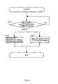
- the controller determines that the measurement value has become less than or equal to the threshold value (S10), sends a close instruction to the ejecting mechanism 40 (S12), and thus the ejecting mechanism 40 closes the valve 42 and stops the ejection of the adhesive agent 4 (see Fig. 1B ).
- the controller sends a detach instruction to the travel path moving mechanism 30 (S14). Then, the air cylinder 35 of the travel path moving mechanism 30 moves the seesaw member 31 to tip about the axis of rotation C31 to switch over the continuous sheet 2 that is in contact with the nozzle 22 to a state where the continuous sheet 2 is spaced apart from the nozzle 22. In other words, simultaneously with the ejection stoppage of the adhesive agent 4 from the nozzle 22, the continuous sheet 2 comes to a state where it is spaced apart from the nozzle 22.
- the adhesive agent 4 continues to eject from the nozzle 22 that is spaced apart from the continuous sheet 2. Also, since ejection is stopped at the same time as coming into the spaced apart state, the adhesive agent 4 that has been ejected from the nozzle 22 is generally transferred to the continuous sheet 2 and transported by the sheet 2. Therefore, the adhesive agent 4 remaining in the nozzle 22 and its surrounding vicinity portion 22a can be reduced and deposition of the adhesive agent 4 can be suppressed.
- ejection stoppage is, for example, a state where the close operation of the valve 42 has been completed and "spaced apart state” is a state where the detaching operation has been completed. Therefore, to be exact, a situation where the "ejection stoppage” and “to come to the spaced apart state” are performed at the same time in accordance with a flowchart of Fig. 2 is a case where an operation time period T42 of the valve 42 and an operation time period T31 of the seesaw member 31 have mutually the same value.
- a speed value greater than zero is set as the above-mentioned threshold value of the travel speed
- Vth is set as the speed value
- the travel of the continuous sheet 2 can be stopped after the ejection stoppage and the detaching.
- the nozzle 22 can be brought to the spaced apart state before stopping the travel of the continuous sheet 2. Therefore, it is possible to prevent the nozzle 22 from being in contact with a part of the continuous sheet 2 for a long time. Accordingly, even if the above-mentioned thermoplastic film is utilized as the continuous sheet 2, it is possible to effectively avoid a situation where a large amount of heat input acts locally on a part of the film and the corresponding part melts and breaks.
- the large value Vth concerning the above-mentioned speed value is, for example, such a speed value that a time required for the travel speed to decrease from Vth to zero is longer than the longer one of the above-mentioned operation time period T42 and the operation time period T31.
- Such speed value Vth can be determined by actually measuring a relationship between each value of the travel speed during reduction of the speed and the time taken from each value to the stoppage of travel.
- the ejection stoppage and the detaching will be performed after the travel of the continuous sheet 2 has been stopped. Therefore, the travel of the continuous sheet 2 is stopped without waiting for the ejection stoppage or the detaching operation. Accordingly, a length of a portion where the adhesive agent 4 is not applied, which may be produced in association with the stoppage of ejection and the detaching, can be reduced (or substantially eliminated). In other words, a waste length of the continuous sheet 2 can be reduced and a yield of the continuous sheet 2 can be improved.
- the controller controls the ejecting mechanism 40 and the travel path moving mechanism 30 in accordance with a flowchart of Fig. 3 .
- the continuous sheet 2 is accelerated by being controlled by the above-mentioned integrated controller. Accordingly, the measurement value of travel speed also becomes gradually greater and eventually exceeds the threshold value.
- the controller of the HMA applying apparatus 20 determines that the measurement value of travel speed is greater than the threshold value (S20). Thus the controller sends the contact instruction to the travel path moving mechanism 30 (S22) and sends the open instruction to the ejecting mechanism 40 (S24). Then, the travel path moving mechanism 30 brings the continuous sheet 2 and the nozzle 22 into a contacting state and the ejecting mechanism 40 opens the valve 42 to eject the adhesive agent 4 from the nozzle 22. Thus, the HMA applying apparatus 20 comes to a steady production state.
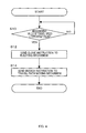
- FIG. 4 is a variant of a flowchart of an operation of an HMA applying apparatus 20 associated with the travel stoppage of the continuous sheet 2.
- the speed of the continuous sheet 2 is reduced by an appropriate control by the integrated controller.
- the signal of the measurement value of travel speed of the continuous sheet 2 is inputted to the controller of the HMA applying apparatus 20 on a real-time basis, and the controller always compares the measurement value of travel speed with the threshold value prestored in the memory.
- the controller determines that the measurement value is less than or equal to the threshold value, i.e., when it has become less than or equal to the threshold value, the controller sends the close instruction to the ejecting mechanism 40 (S12). Then, the ejecting mechanism 40 stops the ejection of the adhesive agent 4 by closing the valve 42.
- the controller After sending of the close instruction, i.e., after a predetermined delay time period Td has elapsed from the sending, the controller sends the detach instruction to the travel path moving mechanism 30 (S14). Then, the air cylinder 35 of the travel path moving mechanism 30 moves the seesaw member 31 to tip about the axis of rotation C31 and thus the continuous sheet 2 is switched over from a state where it is in contact with the nozzle 22 a state where it is spaced apart from the nozzle 22.
- the large value Vth concerning the above-mentioned speed value is, for example, such a speed value that a time required for the travel speed to decrease from Vth to zero is longer than the longer the above-mentioned operation time period T42.
- Such speed value Vth can be determined by actually measuring a relationship between each value of the travel speed during reduction of the speed and the time taken from each value to the stoppage of travel.
- the continuous sheet 2 and the nozzle 22 may be adjusted to come to a spaced apart state before stopping the travel of the continuous sheet 2.
- Td delay time period
- the nozzle 22 can be prevented from coming into contact with a part of the continuous sheet 2 for a long time. Accordingly, even if the above-mentioned thermoplastic film is utilized as the continuous sheet 2, it is possible to effectively avoid a situation where a large amount of heat input acts locally on a part of the film and causing the corresponding part to melt and break.
- the ejection stoppage and the detaching will be performed after the travel of the continuous sheet 2 has been stopped. Therefore, the travel of the continuous sheet 2 is stopped without waiting for the ejection stoppage or the detaching operation. Accordingly, a length of a portion where the adhesive agent 4 is not applied, which may be produced in association with the stoppage of ejection, can be reduced (or substantially eliminated). In other words, a waste length of the continuous sheet 2 can be reduced and a yield of the continuous sheet 2 can be improved.
- Figs. 5A and 5B are schematic side views illustrating an HMA applying apparatus 20a of the second embodiment.
- Fig. 5A shows an adhesive agent (adhesive agent 4)-applying state and
- FIG. 5B shows an application stoppage state.
- a part of the structure e.g., the head 21, etc. is illustrated in a longitudinal cross-sectional view.
- the travel path moving mechanism 30a is arranged in such a manner that one surface 2s of the continuous sheet 2, which is passed across the mechanism 30a, opposes the nozzle 22 of the head 21.
- the mechanism 30a includes a pair of pass line rollers 131a, 131b across which the continuous sheet 2 is passed; a group of rollers 133 arranged at a position between these pass line rollers 131a, 131b and guided in a reciprocable manner along the contacting-detaching direction; and an air cylinder 135 that serves as a driving source that moves the group of rollers 133 in a reciprocable manner in the contacting-detaching direction.
- the pass line rollers 131a, 131b are fixed rollers that are rotatable about respective axes lying along the CD-direction and immovably fixed at predetermined positions.
- the roller 131a nearer to the nozzle 22 in the travel direction is also nearer to the nozzle 22 in the contacting-detaching direction.
- the pass line roller 131a nearer to the nozzle 22 is referred to as a first pass line roller 131a and the farther pass line roller 131b is referred to as a second pass line roller 131b.
- the group of rollers 133 includes an odd number of, for example, three or more (in the illustrated example, three) rollers 133a, 133b, 133c, and the continuous sheet 2 is passed across these rollers 133a, 133b, 133c in a hairpin manner (in the illustrated example, in a U-shaped manner) along the contacting-detaching direction.
- these rollers 133a, 133b, 133c are supported with an appropriate frame member 133f and thus these rollers 133a, 133b, 133c are configured to be movable in a reciprocable manner in the contacting-detaching direction with a relative positional relationship between each other being maintained.
- the nozzle 22 of the head 21 is arranged between the group of rollers 133 and the first pass line roller 131a, which is the pass line roller 131a nearer to the nozzle 22.
- a reference position as a position of the group of rollers 133 at which the continuous sheet 2 comes into contact with the nozzle 22 (see the state shown in Fig. 5A )
- the group of rollers 13 being moved from this reference position and away from the nozzle 22 along the contacting-detaching direction, the continuous sheet 2 will come to a state where it is spaced apart from the nozzle 22 (see the state shown in Fig. 5B ).
- the sheet 2 can be brought back to a state where it is in contact with the nozzle 22.
- This travel path moving mechanism 30a of the second embodiment is also elaborated in that a variation of tension in the continuous sheet 2 when switching between the contacting state and the spaced apart state is suppressed.
- the roller 133a adjacent to the first pass line roller 131a is located at the same position as the first pass line roller 131a or at a position farther than this from the nozzle 22.
- the roller 133c adjacent to the second pass line roller 131b is located at a position nearer to the nozzle 22 than the second pass line roller 131b.
- the path length L2 of the continuous sheet 2 between the first pass line roller 133a and the second pass line roller 131b is kept at a generally constant length.
- a path length L2a of the continuous sheet 2 between the first pass line roller 131a and the roller 133a of the group of rollers 133 becomes longer, whereas a path length L2b of the continuous sheet 2 between the second pass line roller 131b and the roller 133c of the group of rollers 133 becomes shorter. Therefore, the path length L2 of the continuous sheet 2 between the first pass line roller 131a and the second pass line roller 131b is kept at a generally constant length. As a result, a variation of tension in the continuous sheet 2 when switching between the contacting state and the spaced apart state is generally suppressed, and as a result, a meandering problem of the continuous sheet 2 due to the variation of tension can be effectively avoided.
- the absorbent article may be a disposable diaper or a sanitary napkin, but it is not limited thereto as long as it absorbs liquid excretion such as urine or menstrual blood, and may also be, for example, a pet sheet that absorbs liquid excretion from pet animals.
- the nozzle 22 serving as the ejecting section and in contact with the continuous sheet 2 at the tip of the nozzle 22 is shown by way of example, but it is not limited thereto.
- the adhesive agent ejected from the nozzle 22 may be applied to the continuous sheet 2 in such a manner that a member provided at the tip of the nozzle 22 may serve as the ejecting section and come into contact with the continuous sheet 2.
- a rotatable spherical body such as a ball of a ball-pointed pen is provided at the tip of the nozzle 22 and the spherical body moves around due to contact with the continuous sheet 2.
- the travel path moving mechanisms 30, 30a that moves the travel path of the continuous sheet 2 have been shown as an exemplary contacting-detaching mechanism, but it is not limited thereto.
- the contacting state and the spaced apart state may be switched by moving the head 21 towards and away from the continuous sheet 2 in the contacting-detaching direction.
- the contacting-detaching mechanism includes an appropriate guide member such as a linear guide that guides the head 21 in a reciprocable manner in the contacting-detaching direction and a driving source such as an air cylinder or a hydraulic cylinder that reciprocates the head 21 in the contacting-detaching direction.
- the air cylinder 35, 135 is used as the driving source of the travel path moving mechanism 30, 30a, it is not limited thereto, as long as the driving source can move the seesaw member 31 or the group of rollers 133.
- a hydraulic cylinder or an electric motor may be used.
- the travel path of the continuous sheet 2 when in contact with the nozzle 22 is substantially horizontal, but it is not limited there to, and the travel path may extend along a vertical direction or may be inclined at any angle between horizontal and vertical.
Landscapes
- Health & Medical Sciences (AREA)
- Engineering & Computer Science (AREA)
- Life Sciences & Earth Sciences (AREA)
- Animal Behavior & Ethology (AREA)
- Biomedical Technology (AREA)
- Heart & Thoracic Surgery (AREA)
- Vascular Medicine (AREA)
- Epidemiology (AREA)
- Manufacturing & Machinery (AREA)
- General Health & Medical Sciences (AREA)
- Public Health (AREA)
- Veterinary Medicine (AREA)
- Botany (AREA)
- Coating Apparatus (AREA)
- Absorbent Articles And Supports Therefor (AREA)
- Application Of Or Painting With Fluid Materials (AREA)
Abstract

Description
- The present invention relates to an adhesive agent applying apparatus and an adhesive agent applying method that apply a thermoplastic adhesive agent such as a hot melt adhesive agent onto a continuous sheet such as a nonwoven fabric or a film, and that are used in the manufacture of absorbent articles such as disposable diapers.
- Conventionally, on a production line for disposable diapers and the like, a continuous sheet such as a nonwoven fabric or a film is caused to travel continuously along a predetermined travel path, and, during the travel, a hot melt adhesive agent is applied on one of the surfaces of the continuous sheet.
- Such application is performed by a hot melt adhesive agent applying apparatus 20 (hereinafter referred to as an HMA applying apparatus 20) (e.g., see
Fig. 1A ). TheHMA applying apparatus 20 has, for example, a main body which is ahead 21 arranged at a predetermined position on a travel path of acontinuous sheet 2, and thehead 21 has anozzle 22 serving as an ejecting section and opposing thecontinuous sheet 2. With thenozzle 22 being in contact with thecontinuous sheet 2, a hot meltadhesive agent 4 in a molten state is ejected from thenozzle 22 and applied to thecontinuous sheet 2. It is to be noted that, normally, in order to keep the hot meltadhesive agent 4 in a molten state, thehead 21 is heated to, for example, 140°C to 160°C with an appropriate heating mechanism, not shown (e.g., see PTL 1). - [PTL 1]
JP-A-2000-84457 - The production line may be stopped on a regular or irregular basis for various reasons, and in such cases, the travel of the
continuous sheet 2 is also stopped. In such a condition where the travel is stopped, if thenozzle 22 of thehead 21 is kept in contact with thecontinuous sheet 2, thecontinuous sheet 2 will be damaged by heat due to heat input from thehead 21 which is at a high temperature as described above. Particularly, in a case where thecontinuous sheet 2 is a thermoplastic film, since its thickness is small and its heat capacity is low, it will easily melt and break at a contact region. - As an exemplary countermeasure, the above-mentioned heat input can be prevented by spacing the
nozzle 22 apart from thecontinuous sheet 2 when the travel of thecontinuous sheet 2 is stopped (e.g., seeFig. 1B ). - However, in such a case, depending on a relationship between the timing at which ejection of the hot melt
adhesive agent 4 is stopped and the timing of detaching, the detaching may provide a disadvantage in that the deposition of theadhesive agent 4 onto thenozzle 22 and its surroundingvicinity portion 22a is promoted, and thus resulting in another problem that the deposited lump may suddenly peel off from thenozzle 22 and get caught in thecontinuous sheet 2. - More specifically, for example, if the
nozzle 22 and thecontinuous sheet 2 are brought to a spaced-apart state before stopping the ejection of the hot meltadhesive agent 4, theadhesive agent 4 ejected from thenozzle 22 will have nowhere to go (nowhere to be adhered to) and theadhesive agent 4 will deposit on thenozzle 22 and its surroundingvicinity portion 22a. Then, if the lump of the depositedadhesive agent 4 peels off for some reason from thenozzle 22 during the operation of the production line, it will be included in thecontinuous sheet 2 as a foreign material and may cause other problems such as an increased percentage of rejects. - The present invention has been contrived in view of the above-mentioned drawbacks and its object is to suppress deposition of a thermoplastic adhesive agent on an ejecting section and its surrounding vicinity portion.
- In order to achieve the above-described advantages, a principal aspect of the invention is an adhesive agent applying apparatus having an ejecting section that ejects a thermoplastic adhesive agent, the adhesive agent applying apparatus applying the thermoplastic adhesive agent onto one surface of a continuous sheet by ejecting the thermoplastic adhesive agent from the ejecting section, the continuous sheet traveling in a predetermined travel path, the continuous sheet being relevant to an absorbent article, the adhesive agent applying apparatus relevant to an absorbent article including:
- a contacting-detaching mechanism that causes relative movement between the continuous sheet and the ejecting section along a contacting-detaching direction;
- an ejecting mechanism that performs an ejecting operation of the thermoplastic adhesive agent from the ejecting section; and
- a controller that controls the contacting-detaching mechanism and the ejecting mechanism,
- the controller controlling, in a case where a travel speed of the continuous sheet is greater than a predetermined threshold value, the contacting-detaching mechanism and the ejecting mechanism in such a manner that, while causing the ejecting section to be in contact with the one surface of the continuous sheet, the thermoplastic adhesive agent is ejected from the ejecting section, and
- the controller controlling, in a case where the travel speed is less than or equal to the threshold value, the contacting-detaching mechanism and the ejecting mechanism in such a manner that the ejection of the thermoplastic adhesive agent from the ejecting section is stopped and that the continuous sheet and the ejecting section come to a spaced apart state at the time the ejection is stopped or after the ejection has been stopped.
- A further aspect of the invention is an adhesive agent applying method of applying a thermoplastic adhesive agent onto one surface of a continuous sheet by ejecting the thermoplastic adhesive agent from an ejecting section, the continuous sheet traveling in a predetermined travel path, the continuous sheet being relevant to an absorbent article, the adhesive agent applying method relevant to an absorbent article including:
- in a case where a travel speed of the continuous sheet is greater than a predetermined threshold value, ejecting the thermoplastic adhesive agent from the ejecting section while the ejecting section is being in contact with the one surface of the continuous sheet, and
- in a case where the travel speed is less than or equal to the threshold value, stopping the ejection of the thermoplastic adhesive agent from the ejecting section and bringing the continuous sheet and the ejecting section to a spaced apart state at the time the ejection is stopped or after the ejection has been stopped.
- Features of the invention other than the above will become clear by the description of the present specification and the accompanying drawings.
- According to the present invention, the deposition of a thermoplastic adhesive agent on an ejecting section and its surrounding vicinity portion can be suppressed.
-
-
FIG. 1A is a schematic side view illustrating an adhesiveagent applying apparatus 20 of a first embodiment in an adhesive agent (adhesive agent 4)-applying state andFIG. 1B is a schematic side view illustrating an application stoppage state of the same. -
FIG. 2 is a flowchart of an operation of anHMA applying apparatus 20 associated with stoppage of the traveling of thecontinuous sheet 2. -
FIG. 3 is a flowchart of an operation of anHMA applying apparatus 20 when restarting the traveling of thecontinuous sheet 2. -
FIG. 4 is a variant of a flowchart of an operation of anHMA applying apparatus 20 associated with the stoppage of the traveling of thecontinuous sheet 2. -
FIG. 5A is a schematic side view illustrating an adhesiveagent applying apparatus 20a of a second embodiment in an adhesive agent (adhesive agent 4)-applying state andFIG. 5B is a schematic side view illustrating an application stoppage state of the same. - At least the following matters will be made clear by the description of the present specification with reference to the accompanying drawings.
- An adhesive agent applying apparatus having an ejecting section that ejects a thermoplastic adhesive agent is provided in which the adhesive agent applying apparatus applies the thermoplastic adhesive agent onto one surface of a continuous sheet by ejecting the thermoplastic adhesive agent from the ejecting section, the continuous sheet travels in a predetermined travel path, the continuous sheet is relevant to an absorbent article, and in which the adhesive agent applying apparatus relevant to an absorbent article includes:
- a contacting-detaching mechanism that causes relative movement between the continuous sheet and the ejecting section along a contacting-detaching direction;
- an ejecting mechanism that performs an ejecting operation of the thermoplastic adhesive agent from the ejecting section; and
- a controller that controls the contacting-detaching mechanism and the ejecting mechanism,
- the controller controlling, in a case where a travel speed of the continuous sheet is greater than a predetermined threshold value, the contacting-detaching mechanism and the ejecting mechanism in such a manner that, while causing the ejecting section to be in contact with the one surface of the continuous sheet, the thermoplastic adhesive agent is ejected from the ejecting section, and
- the controller controlling, in a case where the travel speed is less than or equal to the threshold value, the contacting-detaching mechanism and the ejecting mechanism in such a manner that the ejection of the thermoplastic adhesive agent from the ejecting section is stopped and that the continuous sheet and the ejecting section come to a spaced apart state at the time the ejection is stopped or after the ejection has been stopped.
- With such adhesive agent applying apparatus relevant to an absorbent article, the continuous sheet and the ejecting section comes to a spaced-apart state at the same time as the stoppage or after the stoppage of ejection of the adhesive agent. Therefore, it is possible to securely avoid a situation where the adhesive agent continues to eject from the ejecting section that is spaced apart from the continuous sheet. Also, since ejection is stopped before coming into the spaced-apart state, the adhesive agent that has been ejected from the ejecting section is generally transferred to the continuous sheet and transported by the sheet. Therefore, the adhesive agent remaining in the ejecting section and its surrounding vicinity portion can be reduced and the deposition of the adhesive agent can be suppressed.
- Preferably, in an adhesive agent applying apparatus relevant to an absorbent article described above, in a case where the travel speed is less than or equal to the threshold value, the controller controls the contacting-detaching mechanism and the ejecting mechanism in such a manner that ejection of the thermoplastic adhesive agent from the ejecting section is stopped and that the continuous sheet and the ejecting section come to a spaced apart state after the ejection has been stopped.
- With such adhesive agent applying apparatus relevant to an absorbent article, the continuous sheet and the ejecting section comes to a spaced-apart state after the stoppage of ejection of the adhesive agent. Therefore, it is possible to securely avoid a situation where the adhesive agent continues to eject from the ejecting section that is spaced apart from the continuous sheet. Also, since ejection is stopped before coming into the spaced-apart state, the adhesive agent that has been ejected from the ejecting section is generally transferred to the continuous sheet and transported by the sheet. Therefore, the adhesive agent remaining in the ejecting section and its surrounding vicinity portion can be reduced and the deposition of the adhesive agent can be suppressed.
- Preferably, in an adhesive agent applying apparatus relevant to an absorbent article described above, the contacting-detaching mechanism is a mechanism that moves the travel path of the continuous sheet in the contacting-detaching direction.
- With such adhesive agent applying apparatus relevant to an absorbent article, the ejecting section can be provided so as not to move and fixed at a predetermined position. Therefore, auxiliary equipment such as a supplying mechanism that supplies the thermoplastic agent to the ejecting section need not be configured as a structure that has a movable section that can move relatively in the contacting-detaching direction. Thus, it is not necessary to consider the problem of leakage of adhesive agent from the movable section, which is likely to occur when a movable section is provided, and thus, designing of the apparatus is facilitated.
- Preferably, in an adhesive agent applying apparatus relevant to an absorbent article described above,
the threshold value is a value greater than zero; and
in a case where the travel speed has become less than or equal to the threshold value, the controller controls the ejecting mechanism in such a manner that ejection is stopped before the travel of the continuous sheet is stopped. - With such adhesive agent applying apparatus relevant to an absorbent article, since the travel of the continuous sheet is stopped after the stoppage of ejection, the adhesive agent remaining in the nozzle after the stoppage of ejection will be wiped off by the traveling continuous sheet. As a result, the adhesive agent remaining in the ejecting section and its surrounding vicinity portion can be effectively reduced and deposition of the deposition material can be further suppressed.
- Preferably, an adhesive agent applying apparatus relevant to an absorbent article described above further includes:
- a heating mechanism that heats the ejecting section,
- wherein the continuous sheet is a thermoplastic sheet, and
- the controller controls the contacting-detaching mechanism in such a manner that, before the travel of the continuous sheet is stopped, the continuous sheet and the ejecting section come to a spaced apart state.
- With such adhesive agent applying apparatus relevant to an absorbent article, cine the thermoplastic adhesive agent is heated, the adhesive agent can be kept at a high fluidity state and a good ejection capability can be maintained.
- Further, since the ejecting section is brought to a spaced-apart state before the stoppage of travel of the continuous sheet, the ejecting section can be prevented from coming into contact with a part of the continuous sheet for a long time. Accordingly, even if the above-mentioned thermoplastic film is utilized as the continuous sheet, it is possible to effectively avoid a situation where a large amount of heat input acts locally on a part of the sheet and causing the corresponding part to melt and break.
- Preferably, in an adhesive agent applying apparatus relevant to an absorbent article described above, the threshold value is set at zero.
- With such adhesive agent applying apparatus relevant to an absorbent article, the travel of the continuous sheet is stopped before the stoppage of travel. In other words, the travel of the continuous sheet is stopped without waiting for the stoppage of ejection. Accordingly, it is possible to reduce (or substantially to eliminate) a length of a section where the adhesive agent is not applied that may occur at the same time as the stoppage of ejection, and, in other words, a waste length of the continuous sheet can be reduced and a yield of the continuous sheet can be improved.
- Further, an adhesive agent applying method of applying a thermoplastic adhesive agent onto one surface of a continuous sheet by ejecting the thermoplastic adhesive agent from an ejecting section is provided in which the continuous sheet travels in a predetermined travel path and the continuous sheet is relevant to an absorbent article, and in which the adhesive agent applying method relevant to an absorbent article includes:
- in a case where a travel speed of the continuous sheet is greater than a predetermined threshold value, ejecting the thermoplastic adhesive agent from the ejecting section while the ejecting section is being in contact with the one surface of the continuous sheet, and
- in a case where the travel speed is less than or equal to the threshold value, stopping the ejection of the thermoplastic adhesive agent from the ejecting section and bringing the continuous sheet and the ejecting section to a spaced apart state at the time the ejection is stopped or after the ejection has been stopped.
- With such adhesive agent applying method relevant to an absorbent article, the continuous sheet and the ejecting section comes to a spaced-apart state at the same time as the stoppage or after the stoppage of ejection of the adhesive agent. Therefore, it is possible to securely avoid a situation where the adhesive agent continues to eject from the ejecting section that is spaced apart from the continuous sheet. Also, since ejection is stopped before coming into the spaced-apart state, the adhesive agent that has been ejected from the ejecting section is generally transferred to the continuous sheet and transported by the sheet. Therefore, the adhesive agent remaining in the ejecting section and its surrounding vicinity portion can be reduced and the deposition of the adhesive agent can be suppressed.
-
Figs. 1A and 1B are schematic side views of an adhesiveagent applying apparatus 20 of a first embodiment.FIG. 1A shows an adhesive agent (adhesive agent 4)-applying state andFIG. 1B shows an application stoppage state. Also, inFigs. 1A and 1B , a part of the structure (e.g., ahead 21, etc.) is shown in a longitudinal cross-sectional view. - The adhesive
agent applying apparatus 20 is used on a production line of absorbent articles such as disposable diapers and sanitary napkins. In other words, as shown inFig. 1A , the applyingapparatus 20 applies the thermoplasticadhesive agent 4 on onesurface 2s of acontinuous sheet 2 that is traveling, as a component of an absorbent article, along a predetermined travel path on the production line. At a position downstream of the applyingapparatus 20 along the travel path, acontinuous sheet 6, a single cut sheet and others, that are other components, are superposed and integrally joined as appropriate at portions where theadhesive agent 4 has been applied, and then continuously transported as asemi-finished product 8 of the absorbent article to downstream processes. - The
continuous sheet 2 may be, for example, a non-woven fabric, a woven fabric, a film, etc. An exemplary material may be a thermoplastic resin, but it is not limited there to and may also be a pulp fiber. - An exemplary thermoplastic
adhesive agent 4 may be hot melt adhesive, but it is not limited thereto. In other words, as long as theadhesive agent 4 has an appropriate thermoplastic property, melts by being heated and can be applied in a fluid state, any adhesive agent other than hot melt adhesive may be used. The following description is based on the assumption that hot melt adhesive is used, and theadhesive agent 4 may be simply referred to as anadhesive agent 4 and the adhesiveagent applying apparatus 20 may be is referred to as anHMA applying apparatus 20. - In the following description, a direction of travel of the
continuous sheet 2 traveling on a production line is referred to as MD-direction and a width direction of thecontinuous sheet 2 is referred to as CD-direction. InFig. 1A , MD-direction is any direction parallel to a plane of paper ofFig. 1A and the MD-direction includes an up-down direction, and the CD-direction is a direction that penetrates through the plane of paper ofFig. 1A . - The
HMA applying apparatus 20 includes: thehead 21 having anozzle 22, which serves as an ejecting section of the hot meltadhesive agent 4; a travelpath moving mechanism 30, which serves as a contacting-detaching mechanism, that moves a travel path of thecontinuous sheet 2 in a direction in which one surface 2S of thecontinuous sheet 2 comes into contact with and detach from thenozzle 22 of the head 21 (corresponds to a thickness direction of thecontinuous sheet 2 or also corresponds to a direction normal to the one surface 2S of thecontinuous sheet 2, hereinafter simply referred to as "contacting-detaching direction); anejecting mechanism 40 that performs an ejecting operation of theadhesive agent 4 from thenozzle 22 of thehead 21; and a controller, not shown, that controls the travelpath moving mechanism 30 and theejecting mechanism 40. - Basically, as shown in
Fig. 1A , theadhesive agent 4 is applied to thecontinuous sheet 2 by ejecting theadhesive agent 4 from thenozzle 22 in a state where onesurface 2s of thecontinuous sheet 2 is in contact with thenozzle 22 of thehead 21 while thecontinuous sheet 2 is traveling, and on the other hand, in a case where theadhesive agent 4 is not applied for a long period of time, for example when the travel of thecontinuous sheet 2 is being stopped, thecontinuous sheet 2 comes to a state where it is spaced apart from thenozzle 22 of thehead 21, as shown inFig. 1B . Then, because of this spacing, particularly in a case where thecontinuous sheet 2 is a thermoplastic film, thermal damages such as melting and breaking of the film can be effectively avoided. - In other words, the
head 21 is heated to, for example, 140°C to 160°C, with an appropriate heating mechanism such as an electric heater, which is not shown in the drawings, in order to ensure the fluidity of theadhesive agent 4. Therefore, if thenozzle 22 is in contact with thecontinuous sheet 2 during the travel stoppage state of thecontinuous sheet 2, the contacting portion of thecontinuous sheet 2 will suffer from thermal damages such as melting and breaking due to heat input from thenozzle 22. Concerning this point, with thecontinuous sheet 2 being spaced apart from thenozzle 22 in the travel stoppage state as described above, the heat input from thenozzle 22 is shut off and the thermal damages of thecontinuous sheet 2 is avoided. - The spaced apart state shown in
Fig. 1B is established after stopping the ejection of theadhesive agent 4. Therefore, it is possible to avoid a situation where theadhesive agent 4 continues to eject from thenozzle 22 that is being spaced apart from thecontinuous sheet 2, and thus deposition of theadhesive agent 4 onto thenozzle 22 and its surroundingvicinity portion 22a can be suppressed. This will be described later. - Hereinafter, each of the
constituent elements - As shown In
Fig. 1A , thehead 21 is fixedly supported at a predetermined position on the travel path of thecontinuous sheet 2 in an immobilized manner by an appropriate supporting member (not shown) such as a so-called face plate. Thenozzle 22 of thehead 21 is arranged to oppose onesurface 2s of thecontinuous sheet 2. In this example, thenozzle 22 is configured as a single slit along the CD-direction, but it is not limited thereto and may be of a configuration in which a plurality of holes are arranged along the CD-direction. Aflow channel 24 that communicates with thenozzle 22 is provided inside thehead 21 and theadhesive agent 4 is delivered to theflow channel 24 with a pump, not shown, which is provided outside. Also, avalve 42 serving as theejecting mechanism 40 and that opens and closes theflow channel 24 is provided in theflow channel 24. The opening-closing operation of thevalve 42 is controlled with the above-mentioned controller and, in an open state of thevalve 42 shown inFig. 1A , theadhesive agent 4 is ejected from thenozzle 22, and in the closed state shown inFig. 1B , the ejection is stopped. - In detail, with the
ejecting mechanism 40 of the illustrated example, thevalve 42 includes avalve seat 42a and avalve member 42b having a spool-like shape that comes into contact with and detaches from thevalve seat 42a.Compressed air 44 is used as an operating fluid that drives thevalve member 42b in a contacting-detaching manner, and it is further configured in such a manner that an on-off operation of the supply of thecompressed air 44 is performed by a solenoid valve, not shown. Therefore, as the controller sends an open instruction to the solenoid valve, the solenoid valve supplies thecompressed air 44 to thevalve 42, as shown inFig. 1A , and due to the pressure built by thecompressed air 44, thevalve element 42b is caused to move against a compression spring force of thecompression spring member 46 in a direction away from thevalve seat 42a, and thus theflow channel 24 opens. On the other hand, as the controller sends a close instruction, the solenoid valve stops supplying thecompressed air 44, as shown inFig. 1B , and thevalve element 42b is caused to move in a direction to come into contact with thevalve seat 42a due to the compression spring force of thecompression spring member 46, and theflow channel 24 closes. However, the configuration of theejecting mechanism 40 is not limited thereto, and configuration other than this may be used. - As has been described above, the travel
path moving mechanism 30 moves along the travel path of thecontinuous sheet 2 in a thickness direction (contacting-detaching direction) to bring thecontinuous sheet 2 and thenozzle 22 into a contacting state or into a spaced-apart state. In this example, a seesaw structure is utilized. In other words, as shown inFig. 1A , themechanism 30 includes aseesaw member 31 supported in a swingable and rotatable manner about an axis of rotation C31 extending in the CD-direction and anair cylinder 35 serving as a driving source that swingably drives theseesaw member 31, and further,rollers seesaw member 31 in a rotatable manner about axes of rotation extending in the CD-direction. Thecontinuous sheet 2 is provided along a peripheral surface of each of therollers continuous sheet 2 does not come off from the peripheral surface. - Accordingly, as the
seesaw member 31 tips from a substantially horizontal position (a position shown inFig. 1A ) where thecontinuous sheet 2 is in contact with thenozzle 22 of thehead 21 in such a manner that theroller 33a proximate to thenozzle 22 moves in a direction away from thenozzle 22, thecontinuous sheet 2 will come to a state where it is spaced apart from thenozzle 22 as shown inFig. 1B . Also, with an opposite operation, thecontinuous sheet 2 will come back to a state where it is in contact with thenozzle 22. - Further, the
mechanism 30 has theseesaw member 31 as its main body. Therefore, a change in a tension of thecontinuous sheet 2 which may arise when switching from the above-mentioned contacting state to a spaced apart state can be effectively suppressed, and as a result, a meandering problem of thecontinuous sheet 2 due to the change in tension can be effectively avoided. - In detail, first, when changing over from the contacting state to the spaced-apart state as described above, the pair of
rollers roller 33b farther from the nozzle 22 (hereinafter referred to as asecond roller 33b) moves generally in a direction opposite to theroller 33a nearer to the nozzle 22 (hereinafter referred to as afirst roller 33a) in the contacting-detaching direction by an amount of displacement of theroller 33a in the contacting-detaching direction (InFig. 1A , an up-down direction). Therefore, a path length L2 of thecontinuous sheet 2 across a pair ofpass line rollers seesaw member 31 along the travel path does not depend on the changing over from the contacting state shown inFig. 1A to the spaced-apart state shown inFig. 1B , and is kept in a generally constant length. As a result, the variation of tension in thecontinuous sheet 2 due to the switching over from the contacting state to the spaced apart state can be generally suppressed. - It has been described in the description above that the
continuous sheet 2 is provided across thefirst roller 33a and thesecond roller 33b in such a manner that thecontinuous sheet 2 is kept so as not to come off from the peripheral surface of each of therollers seesaw member 31 swings, and this is achieved by adjusting positions of the pair ofpass line rollers seesaw member 31. In other words, each of the pair ofpass line rollers pass line rollers continuous sheet 2, whichsurface 2s being opposite to the surface in contact with thefirst roller 33a and thesecond roller 33b. Thepass line roller 80a nearer to thefirst roller 33a is arranged in such a manner that thecontinuous sheet 2 is provided in a substantially S-shape between thepass line roller 80a and thefirst roller 33a, and further, thepass line roller 80b nearer to thesecond roller 33b is arranged in such a manner that thecontinuous sheet 2 is provided in a substantially S-shape between thepass line roller 80b and thesecond roller 33b. Thus, thecontinuous sheet 2 does not depend on the swinging of theseesaw member 31 and does not come off from the peripheral surface of thefirst roller 33a and the peripheral surface of thesecond roller 33b. - The controller is, for example, a computer or a PLC (programmable logic controller) and has a processor and a memory. The processor reads out and executes an appropriate program stored in the memory and sends various instructions to the travel
path moving mechanism 30 and theejecting mechanism 40 to control operations of thesemechanisms - It is to be noted that a measurement value of travel speed of the
continuous sheet 2 is utilized in such control, and a signal representing the measurement value of travel speed is inputted into the controller on a real-time basis from arotary encoder 55 provided on a roller that rotates in synchronization with thecontinuous sheet 2. The roller on which theencoder 55 is attached may be, for example, one of a pair ofpressing rolls pass line roller 80a and thepass line roller 80b, and presses thecontinuous sheet 2, and in the illustrated example, theencoder 55 is provided on thepressing roll 83b, but it is not limited thereto. - Now, referring to a flowchart of
Fig. 2 , an operation of theHMA applying apparatus 20 associated with travel stoppage of thecontinuous sheet 2 will be described. - First, as has been described above, the signal of the measurement value of travel speed of the
continuous sheet 2 is inputted on a real-time basis to the controller of theHMA applying apparatus 20 and the controller always compares whether the measurement value of travel speed is less than or equal to a threshold value that is prestored in the memory. - During a steady production shown in
Fig. 1A , since the travel speed is generally greater than the above-mentioned threshold value, the controller determines that the measurement value of travel speed is greater than the threshold value, and thus the controller sends an open instruction to theejecting mechanism 40 and sends a contact instruction to the travelpath moving mechanism 30. Accordingly, theejecting mechanism 40 opens thevalve 42 and ejects theadhesive agent 4, and the travelpath moving mechanism 30 causes thecontinuous sheet 2 and thenozzle 22 to come into the contacting state. - On the other hand, in order to stop the travel of the
continuous sheet 2, when a speed of thecontinuous sheet 2 is reduced by a control of an appropriate integrated controller, the measurement value of the travel speed will gradually decrease and eventually becomes less than or equal to the threshold value. Then, the controller determines that the measurement value has become less than or equal to the threshold value (S10), sends a close instruction to the ejecting mechanism 40 (S12), and thus theejecting mechanism 40 closes thevalve 42 and stops the ejection of the adhesive agent 4 (seeFig. 1B ). - Simultaneously with the sending of the close instruction to the
ejecting mechanism 40, the controller sends a detach instruction to the travel path moving mechanism 30 (S14). Then, theair cylinder 35 of the travelpath moving mechanism 30 moves theseesaw member 31 to tip about the axis of rotation C31 to switch over thecontinuous sheet 2 that is in contact with thenozzle 22 to a state where thecontinuous sheet 2 is spaced apart from thenozzle 22. In other words, simultaneously with the ejection stoppage of theadhesive agent 4 from thenozzle 22, thecontinuous sheet 2 comes to a state where it is spaced apart from thenozzle 22. - Therefore, it is possible to securely avoid a situation where the
adhesive agent 4 continues to eject from thenozzle 22 that is spaced apart from thecontinuous sheet 2. Also, since ejection is stopped at the same time as coming into the spaced apart state, theadhesive agent 4 that has been ejected from thenozzle 22 is generally transferred to thecontinuous sheet 2 and transported by thesheet 2. Therefore, theadhesive agent 4 remaining in thenozzle 22 and its surroundingvicinity portion 22a can be reduced and deposition of theadhesive agent 4 can be suppressed. - It is to be noted that the above-mentioned "ejection stoppage" is, for example, a state where the close operation of the
valve 42 has been completed and "spaced apart state" is a state where the detaching operation has been completed. Therefore, to be exact, a situation where the "ejection stoppage" and "to come to the spaced apart state" are performed at the same time in accordance with a flowchart ofFig. 2 is a case where an operation time period T42 of thevalve 42 and an operation time period T31 of theseesaw member 31 have mutually the same value. That is to say, such situation is established when the operation time period T42, from the sending of the close instruction to the completion of the closing operation of thevalve 42, and the operation time period T31, from the sending of the detach instruction to the completion of the detaching operation have mutually the same value. Regarding this point, in practice, there are many cases where the operation time period T42 and the operation time period T31 are different from each other. In such a case, a timing of ejection stoppage and a timing of coming to a spaced apart state can be synchronized by delaying the sending of one of the close instruction and the detach instruction that has a shorter operation time period by a deviation between the operation time period T42 and the operation time period T31. - Further, in a case where a speed value greater than zero is set as the above-mentioned threshold value of the travel speed, if a large value Vth is set as the speed value, the travel of the
continuous sheet 2 can be stopped after the ejection stoppage and the detaching. In other words, thenozzle 22 can be brought to the spaced apart state before stopping the travel of thecontinuous sheet 2. Therefore, it is possible to prevent thenozzle 22 from being in contact with a part of thecontinuous sheet 2 for a long time. Accordingly, even if the above-mentioned thermoplastic film is utilized as thecontinuous sheet 2, it is possible to effectively avoid a situation where a large amount of heat input acts locally on a part of the film and the corresponding part melts and breaks. - The large value Vth concerning the above-mentioned speed value is, for example, such a speed value that a time required for the travel speed to decrease from Vth to zero is longer than the longer one of the above-mentioned operation time period T42 and the operation time period T31. Such speed value Vth can be determined by actually measuring a relationship between each value of the travel speed during reduction of the speed and the time taken from each value to the stoppage of travel.
- On the other hand, if zero is set as the above-mentioned threshold value of the travel speed, the ejection stoppage and the detaching will be performed after the travel of the
continuous sheet 2 has been stopped. Therefore, the travel of thecontinuous sheet 2 is stopped without waiting for the ejection stoppage or the detaching operation. Accordingly, a length of a portion where theadhesive agent 4 is not applied, which may be produced in association with the stoppage of ejection and the detaching, can be reduced (or substantially eliminated). In other words, a waste length of thecontinuous sheet 2 can be reduced and a yield of thecontinuous sheet 2 can be improved. However, in this case, since there is a possibility that thenozzle 22 is kept in contact with a part of thecontinuous sheet 2 for a long time, such a setting is limited to a case where thecontinuous sheet 2 is a sheet of, for example, a nonwoven fabric which shows a certain resistance against heat. - When starting the travel of the
continuous sheet 2 again, the controller controls theejecting mechanism 40 and the travelpath moving mechanism 30 in accordance with a flowchart ofFig. 3 . - In detail, first, in order to start the travel of the
continuous sheet 2 again, thecontinuous sheet 2 is accelerated by being controlled by the above-mentioned integrated controller. Accordingly, the measurement value of travel speed also becomes gradually greater and eventually exceeds the threshold value. - Then, the controller of the
HMA applying apparatus 20 determines that the measurement value of travel speed is greater than the threshold value (S20). Thus the controller sends the contact instruction to the travel path moving mechanism 30 (S22) and sends the open instruction to the ejecting mechanism 40 (S24). Then, the travelpath moving mechanism 30 brings thecontinuous sheet 2 and thenozzle 22 into a contacting state and theejecting mechanism 40 opens thevalve 42 to eject theadhesive agent 4 from thenozzle 22. Thus, theHMA applying apparatus 20 comes to a steady production state. -
FIG. 4 is a variant of a flowchart of an operation of anHMA applying apparatus 20 associated with the travel stoppage of thecontinuous sheet 2. - In the above-mentioned flowchart shown in
Fig. 2 , it is brought to the spaced apart state at the same time as the ejection stoppage, whereas the present variant is configured such that it is brought to the spaced apart state after the ejection stoppage. - In detail, first, in order to stop the travel of the
continuous sheet 2, the speed of thecontinuous sheet 2 is reduced by an appropriate control by the integrated controller. - Also, as has been described above, the signal of the measurement value of travel speed of the
continuous sheet 2 is inputted to the controller of theHMA applying apparatus 20 on a real-time basis, and the controller always compares the measurement value of travel speed with the threshold value prestored in the memory. - In association with the above-mentioned reduction of speed, in a case where the controller determines that the measurement value is less than or equal to the threshold value, i.e., when it has become less than or equal to the threshold value, the controller sends the close instruction to the ejecting mechanism 40 (S12). Then, the
ejecting mechanism 40 stops the ejection of theadhesive agent 4 by closing thevalve 42. - After sending of the close instruction, i.e., after a predetermined delay time period Td has elapsed from the sending, the controller sends the detach instruction to the travel path moving mechanism 30 (S14). Then, the
air cylinder 35 of the travelpath moving mechanism 30 moves theseesaw member 31 to tip about the axis of rotation C31 and thus thecontinuous sheet 2 is switched over from a state where it is in contact with thenozzle 22 a state where it is spaced apart from thenozzle 22. It is to be noted that, here, in a case where the above-mentioned operation time periods T42 and T31 are different from each other, the delay time period Td may be set at a value greater than a value obtained by subtracting the operation time period T31 from the operation time period T42 (=T42-T31) , so that the detaching operation will be made to complete after the completion of the closing operation of thevalve 42, i.e., ejection stoppage. - In this manner, by bringing the
continuous sheet 2 and thenozzle 22 to a spaced apart state after the ejection stoppage, an effect described below can be achieved. First, it is possible to securely avoid a situation in which theadhesive agent 4 continues to eject from thenozzle 22 spaced part from thecontinuous sheet 2. Also, since it comes to a spaced-apart state after the ejection has been stopped, theadhesive agent 4 that has been ejected from thenozzle 22 will be transferred to thecontinuous sheet 2 and transported by thesheet 2. Therefore, theadhesive agent 4 remaining in thenozzle 22 and its surroundingvicinity portion 22a can be reduced and deposition of theadhesive agent 4 can be suppressed. - Also, in a case where a speed value greater than zero is set as the above-mentioned threshold value for the travel speed, when a large value Vth is set as the speed value, the travel of the
continuous sheet 2 can be stopped after the ejection stoppage. Therefore, theadhesive agent 4 remaining in thenozzle 22 after the ejection stoppage will be wiped off by the travelingcontinuous sheet 2. In other words, after the ejection stoppage, a long length of thecontinuous sheet 2 in the travel direction in contact with thenozzle 22 can be ensured, and thus a length of thecontinuous sheet 2 for wiping theadhesive agent 4 remaining in the nozzle 22 (wiping length) can be increased. As a result, theadhesive agent 4 remaining in thenozzle 22 and its surroundingvicinity portion 22a can be effectively reduced and deposition of theadhesive agent 4 can be further suppressed. - It is to be noted that the large value Vth concerning the above-mentioned speed value is, for example, such a speed value that a time required for the travel speed to decrease from Vth to zero is longer than the longer the above-mentioned operation time period T42. Such speed value Vth can be determined by actually measuring a relationship between each value of the travel speed during reduction of the speed and the time taken from each value to the stoppage of travel.
- Further, depending on the setting of the above-mentioned delay time period Td that is a time period between the sending of the close instruction (S12) and the sending of the detach instruction (S14), the
continuous sheet 2 and thenozzle 22 may be adjusted to come to a spaced apart state before stopping the travel of thecontinuous sheet 2. By adjusting in such a manner, since thenozzle 22 is spaced apart before stopping the travel of thecontinuous sheet 2, thenozzle 22 can be prevented from coming into contact with a part of thecontinuous sheet 2 for a long time. Accordingly, even if the above-mentioned thermoplastic film is utilized as thecontinuous sheet 2, it is possible to effectively avoid a situation where a large amount of heat input acts locally on a part of the film and causing the corresponding part to melt and break. - On the other hand, if zero is set as the above-mentioned threshold value, the ejection stoppage and the detaching will be performed after the travel of the
continuous sheet 2 has been stopped. Therefore, the travel of thecontinuous sheet 2 is stopped without waiting for the ejection stoppage or the detaching operation. Accordingly, a length of a portion where theadhesive agent 4 is not applied, which may be produced in association with the stoppage of ejection, can be reduced (or substantially eliminated). In other words, a waste length of thecontinuous sheet 2 can be reduced and a yield of thecontinuous sheet 2 can be improved. However, in this case, since there is a possibility that thenozzle 22 is kept in contact with a part of thecontinuous sheet 2 for a long time, such a setting is limited to a case where thecontinuous sheet 2 is a sheet of, for example, a nonwoven fabric which shows a certain resistance against heat. -
Figs. 5A and 5B are schematic side views illustrating anHMA applying apparatus 20a of the second embodiment.Fig. 5A shows an adhesive agent (adhesive agent 4)-applying state andFIG. 5B shows an application stoppage state. Also, inFigs. 5A and 5B , a part of the structure (e.g., thehead 21, etc.) is illustrated in a longitudinal cross-sectional view. - As can be elucidated by referring to
Figs. 5A and 5B , the difference from the first embodiment resides in the configuration of a travel path moving mechanism 30a. Therefore, the following description is mainly directed to the travel path moving mechanism 30a. Other identical structures will be indicated with the same reference numerals and explanations thereof will be omitted. - As shown in
Fig. 5A , the travel path moving mechanism 30a is arranged in such a manner that onesurface 2s of thecontinuous sheet 2, which is passed across the mechanism 30a, opposes thenozzle 22 of thehead 21. The mechanism 30a includes a pair ofpass line rollers continuous sheet 2 is passed; a group of rollers 133 arranged at a position between thesepass line rollers air cylinder 135 that serves as a driving source that moves the group of rollers 133 in a reciprocable manner in the contacting-detaching direction. - The
pass line rollers pass line rollers roller 131a nearer to thenozzle 22 in the travel direction is also nearer to thenozzle 22 in the contacting-detaching direction. Hereinafter, thepass line roller 131a nearer to thenozzle 22 is referred to as a firstpass line roller 131a and the fartherpass line roller 131b is referred to as a secondpass line roller 131b. - The group of rollers 133 includes an odd number of, for example, three or more (in the illustrated example, three)
rollers continuous sheet 2 is passed across theserollers rollers appropriate frame member 133f and thus theserollers nozzle 22 of thehead 21 is arranged between the group of rollers 133 and the firstpass line roller 131a, which is thepass line roller 131a nearer to thenozzle 22. - Accordingly, defining a reference position as a position of the group of rollers 133 at which the
continuous sheet 2 comes into contact with the nozzle 22 (see the state shown inFig. 5A ), with the group of rollers 13 being moved from this reference position and away from thenozzle 22 along the contacting-detaching direction, thecontinuous sheet 2 will come to a state where it is spaced apart from the nozzle 22 (see the state shown inFig. 5B ). Also, with an opposite operation, thesheet 2 can be brought back to a state where it is in contact with thenozzle 22. - This travel path moving mechanism 30a of the second embodiment is also elaborated in that a variation of tension in the
continuous sheet 2 when switching between the contacting state and the spaced apart state is suppressed. Explaining about the elaboration, first, among therollers roller 133a adjacent to the firstpass line roller 131a is located at the same position as the firstpass line roller 131a or at a position farther than this from thenozzle 22. Among therollers roller 133c adjacent to the secondpass line roller 131b is located at a position nearer to thenozzle 22 than the secondpass line roller 131b. - Therefore, even if the group of rollers 133 moves in the contacting-detaching direction, the path length L2 of the
continuous sheet 2 between the firstpass line roller 133a and the secondpass line roller 131b is kept at a generally constant length. In other words, in a case where the group of rollers 133 has moved from the position nearer to thenozzle 22 as shown inFig. 5A to a position farther from thenozzle 22 along the contacting-detaching direction as shown inFig. 5B , a path length L2a of thecontinuous sheet 2 between the firstpass line roller 131a and theroller 133a of the group of rollers 133 becomes longer, whereas a path length L2b of thecontinuous sheet 2 between the secondpass line roller 131b and theroller 133c of the group of rollers 133 becomes shorter. Therefore, the path length L2 of thecontinuous sheet 2 between the firstpass line roller 131a and the secondpass line roller 131b is kept at a generally constant length. As a result, a variation of tension in thecontinuous sheet 2 when switching between the contacting state and the spaced apart state is generally suppressed, and as a result, a meandering problem of thecontinuous sheet 2 due to the variation of tension can be effectively avoided. - It is to be noted that the travel stoppage and travel restart operations of the
HMA applying apparatus 20a using such travel path moving mechanism 30a is generally similar to those explained in the first embodiment, and thus the explanation thereof will be omitted. - Although the embodiments of the present invention have been described above, the present invention is not limited to such embodiments, and variants described below are also possible.
- In the aforementioned embodiments, it has been described that the absorbent article may be a disposable diaper or a sanitary napkin, but it is not limited thereto as long as it absorbs liquid excretion such as urine or menstrual blood, and may also be, for example, a pet sheet that absorbs liquid excretion from pet animals.
- In the aforementioned embodiments, the
nozzle 22 serving as the ejecting section and in contact with thecontinuous sheet 2 at the tip of thenozzle 22 is shown by way of example, but it is not limited thereto. In other words, the adhesive agent ejected from thenozzle 22 may be applied to thecontinuous sheet 2 in such a manner that a member provided at the tip of thenozzle 22 may serve as the ejecting section and come into contact with thecontinuous sheet 2. One of the examples is a configuration in which a rotatable spherical body such as a ball of a ball-pointed pen is provided at the tip of thenozzle 22 and the spherical body moves around due to contact with thecontinuous sheet 2. - In the aforementioned embodiments, the travel
path moving mechanisms 30, 30a that moves the travel path of thecontinuous sheet 2 have been shown as an exemplary contacting-detaching mechanism, but it is not limited thereto. For example, contrary to the above-mentioned embodiments, with a configuration in which the travel path of thecontinuous sheet 2 in the above-mentioned contacting-detaching direction is switched and thehead 21 is reciprocable in the contacting-detaching direction, the contacting state and the spaced apart state may be switched by moving thehead 21 towards and away from thecontinuous sheet 2 in the contacting-detaching direction. In such a case, the contacting-detaching mechanism includes an appropriate guide member such as a linear guide that guides thehead 21 in a reciprocable manner in the contacting-detaching direction and a driving source such as an air cylinder or a hydraulic cylinder that reciprocates thehead 21 in the contacting-detaching direction. - In the aforementioned embodiments, although the
air cylinder path moving mechanism 30, 30a, it is not limited thereto, as long as the driving source can move theseesaw member 31 or the group of rollers 133. For example, a hydraulic cylinder or an electric motor may be used. - In the aforementioned embodiments, the travel path of the
continuous sheet 2 when in contact with thenozzle 22 is substantially horizontal, but it is not limited there to, and the travel path may extend along a vertical direction or may be inclined at any angle between horizontal and vertical. -
- 2 continuous sheet, 2s one surface, 4 thermoplastic adhesive,
- 6 continuous sheet, 8 semifinished product,
- 20 adhesive agent applying apparatus, 20a adhesive agent applying apparatus,
- 21 head, 22 nozzle (ejecting section),
- 22a surrounding vicinity portion,
- 24 flow channel,
- 30 travel path moving mechanism (contacting-detaching mechanism),
- 30a travel path moving mechanism (contacting-detaching mechanism),
- 31 seesaw member, 33a first roller, 33b second roller,
- 35 air cylinder, 40 ejecting mechanism, 42 valve,
- 42a valve seat, 42b valve element, 44 compressed air,
- 46 compression spring member, 55 rotary encoder,
- 80a pass line roller, 80b pass line roller,
- 83a press roll, 83b press roll,
- 131a first pass line roller, 131b second pass line roller,
- 133 group of rollers, 133a roller, 133c roller,
- 133f frame member, 135 air cylinder,
- C31 axis of rotation
Claims (7)
- An adhesive agent applying apparatus having an ejecting section that ejects a thermoplastic adhesive agent, the adhesive agent applying apparatus applying the thermoplastic adhesive agent onto one surface of a continuous sheet by ejecting the thermoplastic adhesive agent from the ejecting section, the continuous sheet traveling in a predetermined travel path, the continuous sheet being relevant to an absorbent article, the adhesive agent applying apparatus relevant to an absorbent article comprising:a contacting-detaching mechanism that causes relative movement between the continuous sheet and the ejecting section along a contacting-detaching direction;an ejecting mechanism that performs an ejecting operation of the thermoplastic adhesive agent from the ejecting section; anda controller that controls the contacting-detaching mechanism and the ejecting mechanism,the controller controlling, in a case where a travel speed of the continuous sheet is greater than a predetermined threshold value, the contacting-detaching mechanism and the ejecting mechanism in such a manner that, while causing the ejecting section to be in contact with the one surface of the continuous sheet, the thermoplastic adhesive agent is ejected from the ejecting section, andthe controller controlling, in a case where the travel speed is less than or equal to the threshold value, the contacting-detaching mechanism and the ejecting mechanism in such a manner that the ejection of the thermoplastic adhesive agent from the ejecting section is stopped and that the continuous sheet and the ejecting section come to a spaced apart state at the time the ejection is stopped or after the ejection has been stopped.
- An adhesive agent applying apparatus relevant to an absorbent article according to claim 1, wherein in a case where the travel speed is less than or equal to the threshold value, the controller controls the contacting-detaching mechanism and the ejecting mechanism in such a manner that ejection of the thermoplastic adhesive agent from the ejecting section is stopped and that the continuous sheet and the ejecting section come to a spaced apart state after the ejection has been stopped.
- An adhesive agent applying apparatus relevant to an absorbent article according to one of claims 1 and 2, wherein the contacting-detaching mechanism is a mechanism that moves the travel path of the continuous sheet in the contacting-detaching direction.
- An adhesive agent applying apparatus relevant to an absorbent article according to claim 2, wherein,
the threshold value is a value greater than zero; and
in a case where the travel speed has become less than or equal to the threshold value, the controller controls the ejecting mechanism in such a manner that ejection is stopped before the travel of the continuous sheet is stopped. - An adhesive agent applying apparatus relevant to an absorbent article according to claim 4, further comprising:a heating mechanism that heats the ejecting section,wherein the continuous sheet is a thermoplastic sheet, andthe controller controls the contacting-detaching mechanism in such a manner that, before the travel of the continuous sheet is stopped, the continuous sheet and the ejecting section come to a spaced apart state.
- An adhesive agent applying apparatus relevant to an absorbent article according to any one of claims 1 to 3, wherein the threshold value is set at zero.
- An adhesive agent applying method of applying a thermoplastic adhesive agent onto one surface of a continuous sheet by ejecting the thermoplastic adhesive agent from an ejecting section, the continuous sheet traveling in a predetermined travel path, the continuous sheet being relevant to an absorbent article, the adhesive agent applying method relevant to an absorbent article comprising:in a case where a travel speed of the continuous sheet is greater than a predetermined threshold value, ejecting the thermoplastic adhesive agent from the ejecting section while the ejecting section is being in contact with the one surface of the continuous sheet, andin a case where the travel speed is less than or equal to the threshold value, stopping the ejection of the thermoplastic adhesive agent from the ejecting section and bringing the continuous sheet and the ejecting section to a spaced apart state at the time the ejection is stopped or after the ejection has been stopped.
Applications Claiming Priority (2)
| Application Number | Priority Date | Filing Date | Title |
|---|---|---|---|
| JP2010212386A JP5622502B2 (en) | 2010-09-22 | 2010-09-22 | Adhesive coating apparatus and absorbent coating method for absorbent article |
| PCT/JP2011/070976 WO2012039333A1 (en) | 2010-09-22 | 2011-09-14 | Adhesive application device and adhesive application method for absorbent article |
Publications (3)
| Publication Number | Publication Date |
|---|---|
| EP2620131A1 true EP2620131A1 (en) | 2013-07-31 |
| EP2620131A4 EP2620131A4 (en) | 2017-11-29 |
| EP2620131B1 EP2620131B1 (en) | 2019-04-03 |
Family
ID=45873821
Family Applications (1)
| Application Number | Title | Priority Date | Filing Date |
|---|---|---|---|
| EP11826779.8A Not-in-force EP2620131B1 (en) | 2010-09-22 | 2011-09-14 | Adhesive application device and adhesive application method for absorbent article |
Country Status (5)
| Country | Link |
|---|---|
| US (1) | US8899176B2 (en) |
| EP (1) | EP2620131B1 (en) |
| JP (1) | JP5622502B2 (en) |
| CN (1) | CN103118645B (en) |
| WO (1) | WO2012039333A1 (en) |
Families Citing this family (15)
| Publication number | Priority date | Publication date | Assignee | Title |
|---|---|---|---|---|
| US9248057B2 (en) * | 2012-08-16 | 2016-02-02 | Beijing Beishute Maternity & Child Articles., Ltd | Method of applying bulk glue for nursing pad base film to four corners of sanitary product nursing pad base film and device therefor |
| JP2014059256A (en) * | 2012-09-19 | 2014-04-03 | Kao Corp | Foreign matter inspection method and device |
| RU2745016C1 (en) * | 2017-06-23 | 2021-03-18 | Кимберли-Кларк Ворлдвайд, Инк. | System and method of applying glue to a moving belt |
| CN110709550A (en) | 2017-06-23 | 2020-01-17 | 金伯利-克拉克环球有限公司 | Adhesive pattern residing on a moving base web |
| WO2019165273A1 (en) * | 2018-02-23 | 2019-08-29 | H.B. Fuller Company | Self-supporting fiberized web including a hot melt composition for use in disposable absorbent articles and application method |
| KR102102435B1 (en) * | 2019-09-04 | 2020-04-20 | 한국건설기술연구원 | Apparatus for manufacturing textile grid for improving adhesion, and method for manufacturing textile grid using the same |
| JP7714873B2 (en) * | 2020-12-01 | 2025-07-30 | 王子ホールディングス株式会社 | Coating method and coating device |
| JP7686959B2 (en) * | 2020-12-01 | 2025-06-03 | 王子ホールディングス株式会社 | Coating method and coating device |
| JP7703841B2 (en) * | 2020-12-01 | 2025-07-08 | 王子ホールディングス株式会社 | Coating method and coating device |
| CN116692551B (en) * | 2022-02-28 | 2026-01-30 | 宁德时代新能源科技股份有限公司 | Material belt turning mechanism, drying device and electrode manufacturing equipment |
| JP2023149183A (en) * | 2022-03-30 | 2023-10-13 | 住ベシート防水株式会社 | Tarpaulin sheet joining device and waterproof sheet joining method |
| CN217774594U (en) * | 2022-05-05 | 2022-11-11 | 宁德时代新能源科技股份有限公司 | Coating system |
| CN115350863B (en) * | 2022-10-14 | 2023-04-25 | 南通国碳自动化设备有限公司 | Carbon fiber silk gumming device |
| CN116236345B (en) * | 2023-02-14 | 2023-10-13 | 无锡优佳无纺科技有限公司 | Processing device and production process of diaper deodorizing composite core |
| IT202400004876A1 (en) * | 2024-03-05 | 2025-09-05 | Itapack S R L | ADHESIVE GROUP |
Family Cites Families (9)
| Publication number | Priority date | Publication date | Assignee | Title |
|---|---|---|---|---|
| US4764242A (en) * | 1986-12-18 | 1988-08-16 | The Kendall Company | Adhesive applying apparatus |
| US4805554A (en) * | 1987-05-22 | 1989-02-21 | Acumeter Laboratories, Inc. | Method of and apparatus for maintaining uniform hot melt coatings on thermally sensitive webs by maintaining dimensional stability of silicone and rubber-like web back-up rolls |
| JP3074307B2 (en) * | 1991-04-30 | 2000-08-07 | 日本エヌエスシー株式会社 | Intermittent coating position shift prevention device |
| WO1996026697A1 (en) * | 1995-02-28 | 1996-09-06 | Tredegar Industries, Inc. | Three-dimensional film formed by melt bonding fibers on the surface of a polymeric film |
| US5766356A (en) * | 1995-07-06 | 1998-06-16 | Toray Engineering Co., Ltd. | Coating apparatus |
| JPH0975814A (en) * | 1995-09-19 | 1997-03-25 | Fuji Photo Film Co Ltd | Coating device |
| JP4212158B2 (en) * | 1998-09-16 | 2009-01-21 | スリーエム カンパニー | Coating device |
| EP1925425A4 (en) * | 2005-09-14 | 2012-08-29 | Fujifilm Corp | Method for producing concave-convex sheet and apparatus for producing concave-convex sheet |
| JP5623021B2 (en) * | 2009-03-02 | 2014-11-12 | ユニ・チャーム株式会社 | Coating device |
-
2010
- 2010-09-22 JP JP2010212386A patent/JP5622502B2/en not_active Expired - Fee Related
-
2011
- 2011-09-14 US US13/825,144 patent/US8899176B2/en not_active Expired - Fee Related
- 2011-09-14 CN CN201180045704.5A patent/CN103118645B/en not_active Expired - Fee Related
- 2011-09-14 WO PCT/JP2011/070976 patent/WO2012039333A1/en not_active Ceased
- 2011-09-14 EP EP11826779.8A patent/EP2620131B1/en not_active Not-in-force
Non-Patent Citations (1)
| Title |
|---|
| See references of WO2012039333A1 * |
Also Published As
| Publication number | Publication date |
|---|---|
| US20130260031A1 (en) | 2013-10-03 |
| EP2620131A4 (en) | 2017-11-29 |
| JP2012066185A (en) | 2012-04-05 |
| CN103118645A (en) | 2013-05-22 |
| WO2012039333A1 (en) | 2012-03-29 |
| US8899176B2 (en) | 2014-12-02 |
| CN103118645B (en) | 2014-10-15 |
| JP5622502B2 (en) | 2014-11-12 |
| EP2620131B1 (en) | 2019-04-03 |
Similar Documents
| Publication | Publication Date | Title |
|---|---|---|
| EP2620131B1 (en) | Adhesive application device and adhesive application method for absorbent article | |
| US8863803B2 (en) | Apparatus for manufacturing absorbent article | |
| EP3092994A1 (en) | Ultrasonic welding device and ultrasonic welding method of sheet-shaped member associated with absorbent article | |
| EP3092995B1 (en) | Ultrasonic welding apparatus and ultrasonic welding method of sheet-like member associated with absorbent article | |
| US9527681B2 (en) | Thin-section sample fabrication apparatus and method of fabricating thin-section sample | |
| EP2562109B1 (en) | Accumulating Apparatus | |
| KR20110127723A (en) | Absorbent article manufacturing device and absorbent article manufacturing method | |
| EP4699589A2 (en) | Methods and apparatuses for altering portions of substrates with vibration energy | |
| JP5235343B2 (en) | Adhesive application nozzle and adhesive application device | |
| CN109152667B (en) | Method for manufacturing absorbent article | |
| JP2013188477A (en) | System and method for applying individually coated non-linear elastic strand to substrate | |
| US6432242B1 (en) | Method for applying elastic to a moving web | |
| JPH07178364A (en) | Curtain coater | |
| JP6303526B2 (en) | Adhesive coating apparatus and method for manufacturing absorbent article using the same | |
| EP3137307B1 (en) | Method and system for automatic preventive maintenance of a non-contact printing unit | |
| JP5399063B2 (en) | Liquid applicator | |
| CN112912226B (en) | Continuous forming method of continuous body | |
| US20230405939A1 (en) | Energy mechanism assemblies and methods of providing energy to an item | |
| EP4197650A1 (en) | A unit for applying glue on continuous elements and related method | |
| WO2019130918A1 (en) | Method of manufacturing absorbent article and device for manufacturing absorbent article | |
| CN210144870U (en) | Sheet manufacturing equipment | |
| JPH06277613A (en) | Blade coater coating method and coating equipment | |
| US20070051308A1 (en) | Quick-change applicator system for coating a passing web | |
| JPH0342169B2 (en) |
Legal Events
| Date | Code | Title | Description |
|---|---|---|---|
| PUAI | Public reference made under article 153(3) epc to a published international application that has entered the european phase |
Free format text: ORIGINAL CODE: 0009012 |
|
| 17P | Request for examination filed |
Effective date: 20130305 |
|
| AK | Designated contracting states |
Kind code of ref document: A1 Designated state(s): AL AT BE BG CH CY CZ DE DK EE ES FI FR GB GR HR HU IE IS IT LI LT LU LV MC MK MT NL NO PL PT RO RS SE SI SK SM TR |
|
| DAX | Request for extension of the european patent (deleted) | ||
| RA4 | Supplementary search report drawn up and despatched (corrected) |
Effective date: 20171102 |
|
| RIC1 | Information provided on ipc code assigned before grant |
Ipc: B05D 7/24 20060101ALI20171025BHEP Ipc: B05D 1/26 20060101ALN20171025BHEP Ipc: B05D 3/00 20060101ALI20171025BHEP Ipc: A61F 13/15 20060101ALI20171025BHEP Ipc: B05C 5/04 20060101AFI20171025BHEP Ipc: B05C 11/10 20060101ALI20171025BHEP Ipc: A61F 13/49 20060101ALI20171025BHEP |
|
| REG | Reference to a national code |
Ref country code: DE Ref legal event code: R079 Ref document number: 602011057819 Country of ref document: DE Free format text: PREVIOUS MAIN CLASS: A61F0013150000 Ipc: B05C0005040000 |
|
| RIC1 | Information provided on ipc code assigned before grant |
Ipc: A61F 13/15 20060101ALI20180912BHEP Ipc: A61F 13/49 20060101ALI20180912BHEP Ipc: B05C 11/10 20060101ALI20180912BHEP Ipc: B05D 3/00 20060101ALI20180912BHEP Ipc: B05D 1/26 20060101ALN20180912BHEP Ipc: B05C 5/04 20060101AFI20180912BHEP Ipc: B05D 7/24 20060101ALI20180912BHEP |
|
| GRAP | Despatch of communication of intention to grant a patent |
Free format text: ORIGINAL CODE: EPIDOSNIGR1 |
|
| STAA | Information on the status of an ep patent application or granted ep patent |
Free format text: STATUS: GRANT OF PATENT IS INTENDED |
|
| INTG | Intention to grant announced |
Effective date: 20181108 |
|
| GRAS | Grant fee paid |
Free format text: ORIGINAL CODE: EPIDOSNIGR3 |
|
| GRAA | (expected) grant |
Free format text: ORIGINAL CODE: 0009210 |
|
| STAA | Information on the status of an ep patent application or granted ep patent |
Free format text: STATUS: THE PATENT HAS BEEN GRANTED |
|
| AK | Designated contracting states |
Kind code of ref document: B1 Designated state(s): AL AT BE BG CH CY CZ DE DK EE ES FI FR GB GR HR HU IE IS IT LI LT LU LV MC MK MT NL NO PL PT RO RS SE SI SK SM TR |
|
| REG | Reference to a national code |
Ref country code: GB Ref legal event code: FG4D |
|
| REG | Reference to a national code |
Ref country code: CH Ref legal event code: EP Ref country code: AT Ref legal event code: REF Ref document number: 1115079 Country of ref document: AT Kind code of ref document: T Effective date: 20190415 |
|
| REG | Reference to a national code |
Ref country code: DE Ref legal event code: R096 Ref document number: 602011057819 Country of ref document: DE |
|
| REG | Reference to a national code |
Ref country code: IE Ref legal event code: FG4D |
|
| REG | Reference to a national code |
Ref country code: NL Ref legal event code: MP Effective date: 20190403 |
|
| REG | Reference to a national code |
Ref country code: LT Ref legal event code: MG4D |
|
| REG | Reference to a national code |
Ref country code: AT Ref legal event code: MK05 Ref document number: 1115079 Country of ref document: AT Kind code of ref document: T Effective date: 20190403 |
|
| PG25 | Lapsed in a contracting state [announced via postgrant information from national office to epo] |
Ref country code: NL Free format text: LAPSE BECAUSE OF FAILURE TO SUBMIT A TRANSLATION OF THE DESCRIPTION OR TO PAY THE FEE WITHIN THE PRESCRIBED TIME-LIMIT Effective date: 20190403 |
|
| PG25 | Lapsed in a contracting state [announced via postgrant information from national office to epo] |
Ref country code: AL Free format text: LAPSE BECAUSE OF FAILURE TO SUBMIT A TRANSLATION OF THE DESCRIPTION OR TO PAY THE FEE WITHIN THE PRESCRIBED TIME-LIMIT Effective date: 20190403 Ref country code: ES Free format text: LAPSE BECAUSE OF FAILURE TO SUBMIT A TRANSLATION OF THE DESCRIPTION OR TO PAY THE FEE WITHIN THE PRESCRIBED TIME-LIMIT Effective date: 20190403 Ref country code: LT Free format text: LAPSE BECAUSE OF FAILURE TO SUBMIT A TRANSLATION OF THE DESCRIPTION OR TO PAY THE FEE WITHIN THE PRESCRIBED TIME-LIMIT Effective date: 20190403 Ref country code: CZ Free format text: LAPSE BECAUSE OF FAILURE TO SUBMIT A TRANSLATION OF THE DESCRIPTION OR TO PAY THE FEE WITHIN THE PRESCRIBED TIME-LIMIT Effective date: 20190403 Ref country code: NO Free format text: LAPSE BECAUSE OF FAILURE TO SUBMIT A TRANSLATION OF THE DESCRIPTION OR TO PAY THE FEE WITHIN THE PRESCRIBED TIME-LIMIT Effective date: 20190703 Ref country code: HR Free format text: LAPSE BECAUSE OF FAILURE TO SUBMIT A TRANSLATION OF THE DESCRIPTION OR TO PAY THE FEE WITHIN THE PRESCRIBED TIME-LIMIT Effective date: 20190403 Ref country code: SE Free format text: LAPSE BECAUSE OF FAILURE TO SUBMIT A TRANSLATION OF THE DESCRIPTION OR TO PAY THE FEE WITHIN THE PRESCRIBED TIME-LIMIT Effective date: 20190403 Ref country code: PT Free format text: LAPSE BECAUSE OF FAILURE TO SUBMIT A TRANSLATION OF THE DESCRIPTION OR TO PAY THE FEE WITHIN THE PRESCRIBED TIME-LIMIT Effective date: 20190803 Ref country code: FI Free format text: LAPSE BECAUSE OF FAILURE TO SUBMIT A TRANSLATION OF THE DESCRIPTION OR TO PAY THE FEE WITHIN THE PRESCRIBED TIME-LIMIT Effective date: 20190403 |
|
| PGFP | Annual fee paid to national office [announced via postgrant information from national office to epo] |
Ref country code: FR Payment date: 20190815 Year of fee payment: 9 Ref country code: DE Payment date: 20190903 Year of fee payment: 9 |
|
| PG25 | Lapsed in a contracting state [announced via postgrant information from national office to epo] |
Ref country code: LV Free format text: LAPSE BECAUSE OF FAILURE TO SUBMIT A TRANSLATION OF THE DESCRIPTION OR TO PAY THE FEE WITHIN THE PRESCRIBED TIME-LIMIT Effective date: 20190403 Ref country code: RS Free format text: LAPSE BECAUSE OF FAILURE TO SUBMIT A TRANSLATION OF THE DESCRIPTION OR TO PAY THE FEE WITHIN THE PRESCRIBED TIME-LIMIT Effective date: 20190403 Ref country code: PL Free format text: LAPSE BECAUSE OF FAILURE TO SUBMIT A TRANSLATION OF THE DESCRIPTION OR TO PAY THE FEE WITHIN THE PRESCRIBED TIME-LIMIT Effective date: 20190403 Ref country code: GR Free format text: LAPSE BECAUSE OF FAILURE TO SUBMIT A TRANSLATION OF THE DESCRIPTION OR TO PAY THE FEE WITHIN THE PRESCRIBED TIME-LIMIT Effective date: 20190704 Ref country code: BG Free format text: LAPSE BECAUSE OF FAILURE TO SUBMIT A TRANSLATION OF THE DESCRIPTION OR TO PAY THE FEE WITHIN THE PRESCRIBED TIME-LIMIT Effective date: 20190703 |
|
| PG25 | Lapsed in a contracting state [announced via postgrant information from national office to epo] |
Ref country code: IS Free format text: LAPSE BECAUSE OF FAILURE TO SUBMIT A TRANSLATION OF THE DESCRIPTION OR TO PAY THE FEE WITHIN THE PRESCRIBED TIME-LIMIT Effective date: 20190803 Ref country code: AT Free format text: LAPSE BECAUSE OF FAILURE TO SUBMIT A TRANSLATION OF THE DESCRIPTION OR TO PAY THE FEE WITHIN THE PRESCRIBED TIME-LIMIT Effective date: 20190403 |
|
| PGFP | Annual fee paid to national office [announced via postgrant information from national office to epo] |
Ref country code: GB Payment date: 20190912 Year of fee payment: 9 |
|
| REG | Reference to a national code |
Ref country code: DE Ref legal event code: R097 Ref document number: 602011057819 Country of ref document: DE |
|
| PG25 | Lapsed in a contracting state [announced via postgrant information from national office to epo] |
Ref country code: SK Free format text: LAPSE BECAUSE OF FAILURE TO SUBMIT A TRANSLATION OF THE DESCRIPTION OR TO PAY THE FEE WITHIN THE PRESCRIBED TIME-LIMIT Effective date: 20190403 Ref country code: RO Free format text: LAPSE BECAUSE OF FAILURE TO SUBMIT A TRANSLATION OF THE DESCRIPTION OR TO PAY THE FEE WITHIN THE PRESCRIBED TIME-LIMIT Effective date: 20190403 Ref country code: DK Free format text: LAPSE BECAUSE OF FAILURE TO SUBMIT A TRANSLATION OF THE DESCRIPTION OR TO PAY THE FEE WITHIN THE PRESCRIBED TIME-LIMIT Effective date: 20190403 Ref country code: EE Free format text: LAPSE BECAUSE OF FAILURE TO SUBMIT A TRANSLATION OF THE DESCRIPTION OR TO PAY THE FEE WITHIN THE PRESCRIBED TIME-LIMIT Effective date: 20190403 |
|
| PLBE | No opposition filed within time limit |
Free format text: ORIGINAL CODE: 0009261 |
|
| STAA | Information on the status of an ep patent application or granted ep patent |
Free format text: STATUS: NO OPPOSITION FILED WITHIN TIME LIMIT |
|
| PG25 | Lapsed in a contracting state [announced via postgrant information from national office to epo] |
Ref country code: SM Free format text: LAPSE BECAUSE OF FAILURE TO SUBMIT A TRANSLATION OF THE DESCRIPTION OR TO PAY THE FEE WITHIN THE PRESCRIBED TIME-LIMIT Effective date: 20190403 Ref country code: IT Free format text: LAPSE BECAUSE OF FAILURE TO SUBMIT A TRANSLATION OF THE DESCRIPTION OR TO PAY THE FEE WITHIN THE PRESCRIBED TIME-LIMIT Effective date: 20190403 |
|
| 26N | No opposition filed |
Effective date: 20200106 |
|
| PG25 | Lapsed in a contracting state [announced via postgrant information from national office to epo] |
Ref country code: TR Free format text: LAPSE BECAUSE OF FAILURE TO SUBMIT A TRANSLATION OF THE DESCRIPTION OR TO PAY THE FEE WITHIN THE PRESCRIBED TIME-LIMIT Effective date: 20190403 |
|
| PG25 | Lapsed in a contracting state [announced via postgrant information from national office to epo] |
Ref country code: MC Free format text: LAPSE BECAUSE OF FAILURE TO SUBMIT A TRANSLATION OF THE DESCRIPTION OR TO PAY THE FEE WITHIN THE PRESCRIBED TIME-LIMIT Effective date: 20190403 Ref country code: SI Free format text: LAPSE BECAUSE OF FAILURE TO SUBMIT A TRANSLATION OF THE DESCRIPTION OR TO PAY THE FEE WITHIN THE PRESCRIBED TIME-LIMIT Effective date: 20190403 |
|
| REG | Reference to a national code |
Ref country code: CH Ref legal event code: PL |
|
| PG25 | Lapsed in a contracting state [announced via postgrant information from national office to epo] |
Ref country code: LI Free format text: LAPSE BECAUSE OF NON-PAYMENT OF DUE FEES Effective date: 20190930 Ref country code: CH Free format text: LAPSE BECAUSE OF NON-PAYMENT OF DUE FEES Effective date: 20190930 Ref country code: LU Free format text: LAPSE BECAUSE OF NON-PAYMENT OF DUE FEES Effective date: 20190914 Ref country code: IE Free format text: LAPSE BECAUSE OF NON-PAYMENT OF DUE FEES Effective date: 20190914 |
|
| REG | Reference to a national code |
Ref country code: BE Ref legal event code: MM Effective date: 20190930 |
|
| PG25 | Lapsed in a contracting state [announced via postgrant information from national office to epo] |
Ref country code: BE Free format text: LAPSE BECAUSE OF NON-PAYMENT OF DUE FEES Effective date: 20190930 |
|
| REG | Reference to a national code |
Ref country code: DE Ref legal event code: R119 Ref document number: 602011057819 Country of ref document: DE |
|
| GBPC | Gb: european patent ceased through non-payment of renewal fee |
Effective date: 20200914 |
|
| PG25 | Lapsed in a contracting state [announced via postgrant information from national office to epo] |
Ref country code: CY Free format text: LAPSE BECAUSE OF FAILURE TO SUBMIT A TRANSLATION OF THE DESCRIPTION OR TO PAY THE FEE WITHIN THE PRESCRIBED TIME-LIMIT Effective date: 20190403 |
|
| PG25 | Lapsed in a contracting state [announced via postgrant information from national office to epo] |
Ref country code: DE Free format text: LAPSE BECAUSE OF NON-PAYMENT OF DUE FEES Effective date: 20210401 Ref country code: MT Free format text: LAPSE BECAUSE OF FAILURE TO SUBMIT A TRANSLATION OF THE DESCRIPTION OR TO PAY THE FEE WITHIN THE PRESCRIBED TIME-LIMIT Effective date: 20190403 Ref country code: HU Free format text: LAPSE BECAUSE OF FAILURE TO SUBMIT A TRANSLATION OF THE DESCRIPTION OR TO PAY THE FEE WITHIN THE PRESCRIBED TIME-LIMIT; INVALID AB INITIO Effective date: 20110914 Ref country code: FR Free format text: LAPSE BECAUSE OF NON-PAYMENT OF DUE FEES Effective date: 20200930 |
|
| PG25 | Lapsed in a contracting state [announced via postgrant information from national office to epo] |
Ref country code: GB Free format text: LAPSE BECAUSE OF NON-PAYMENT OF DUE FEES Effective date: 20200914 |
|
| PG25 | Lapsed in a contracting state [announced via postgrant information from national office to epo] |
Ref country code: MK Free format text: LAPSE BECAUSE OF FAILURE TO SUBMIT A TRANSLATION OF THE DESCRIPTION OR TO PAY THE FEE WITHIN THE PRESCRIBED TIME-LIMIT Effective date: 20190403 |