EP2620123A1 - Tool for milling bone tissue, especially for sinus lifting according to the summers technique or for positioning extra-short implants - Google Patents
Tool for milling bone tissue, especially for sinus lifting according to the summers technique or for positioning extra-short implants Download PDFInfo
- Publication number
- EP2620123A1 EP2620123A1 EP11788190.4A EP11788190A EP2620123A1 EP 2620123 A1 EP2620123 A1 EP 2620123A1 EP 11788190 A EP11788190 A EP 11788190A EP 2620123 A1 EP2620123 A1 EP 2620123A1
- Authority
- EP
- European Patent Office
- Prior art keywords
- tool
- cutting
- longitudinal axis
- bone
- main body
- Prior art date
- Legal status (The legal status is an assumption and is not a legal conclusion. Google has not performed a legal analysis and makes no representation as to the accuracy of the status listed.)
- Granted
Links
Images


Classifications
-
- A—HUMAN NECESSITIES
- A61—MEDICAL OR VETERINARY SCIENCE; HYGIENE
- A61C—DENTISTRY; APPARATUS OR METHODS FOR ORAL OR DENTAL HYGIENE
- A61C8/00—Means to be fixed to the jaw-bone for consolidating natural teeth or for fixing dental prostheses thereon; Dental implants; Implanting tools
-
- A—HUMAN NECESSITIES
- A61—MEDICAL OR VETERINARY SCIENCE; HYGIENE
- A61C—DENTISTRY; APPARATUS OR METHODS FOR ORAL OR DENTAL HYGIENE
- A61C3/00—Dental tools or instruments
- A61C3/02—Tooth drilling or cutting instruments; Instruments acting like a sandblast machine
-
- A—HUMAN NECESSITIES
- A61—MEDICAL OR VETERINARY SCIENCE; HYGIENE
- A61C—DENTISTRY; APPARATUS OR METHODS FOR ORAL OR DENTAL HYGIENE
- A61C8/00—Means to be fixed to the jaw-bone for consolidating natural teeth or for fixing dental prostheses thereon; Dental implants; Implanting tools
- A61C8/0089—Implanting tools or instruments
-
- A—HUMAN NECESSITIES
- A61—MEDICAL OR VETERINARY SCIENCE; HYGIENE
- A61C—DENTISTRY; APPARATUS OR METHODS FOR ORAL OR DENTAL HYGIENE
- A61C8/00—Means to be fixed to the jaw-bone for consolidating natural teeth or for fixing dental prostheses thereon; Dental implants; Implanting tools
- A61C8/0003—Not used, see subgroups
- A61C8/0004—Consolidating natural teeth
- A61C8/0006—Periodontal tissue or bone regeneration
-
- A—HUMAN NECESSITIES
- A61—MEDICAL OR VETERINARY SCIENCE; HYGIENE
- A61C—DENTISTRY; APPARATUS OR METHODS FOR ORAL OR DENTAL HYGIENE
- A61C8/00—Means to be fixed to the jaw-bone for consolidating natural teeth or for fixing dental prostheses thereon; Dental implants; Implanting tools
- A61C8/0089—Implanting tools or instruments
- A61C8/0092—Implanting tools or instruments for sinus lifting
-
- A—HUMAN NECESSITIES
- A61—MEDICAL OR VETERINARY SCIENCE; HYGIENE
- A61B—DIAGNOSIS; SURGERY; IDENTIFICATION
- A61B17/00—Surgical instruments, devices or methods
- A61B17/16—Instruments for performing osteoclasis; Drills or chisels for bones; Trepans
-
- A—HUMAN NECESSITIES
- A61—MEDICAL OR VETERINARY SCIENCE; HYGIENE
- A61B—DIAGNOSIS; SURGERY; IDENTIFICATION
- A61B17/00—Surgical instruments, devices or methods
- A61B17/16—Instruments for performing osteoclasis; Drills or chisels for bones; Trepans
- A61B17/1613—Component parts
- A61B17/1615—Drill bits, i.e. rotating tools extending from a handpiece to contact the worked material
-
- A—HUMAN NECESSITIES
- A61—MEDICAL OR VETERINARY SCIENCE; HYGIENE
- A61B—DIAGNOSIS; SURGERY; IDENTIFICATION
- A61B17/00—Surgical instruments, devices or methods
- A61B17/16—Instruments for performing osteoclasis; Drills or chisels for bones; Trepans
- A61B17/1613—Component parts
- A61B17/1633—Sleeves, i.e. non-rotating parts surrounding the bit shaft, e.g. the sleeve forming a single unit with the bit shaft
-
- A—HUMAN NECESSITIES
- A61—MEDICAL OR VETERINARY SCIENCE; HYGIENE
- A61B—DIAGNOSIS; SURGERY; IDENTIFICATION
- A61B17/00—Surgical instruments, devices or methods
- A61B17/16—Instruments for performing osteoclasis; Drills or chisels for bones; Trepans
- A61B17/1662—Instruments for performing osteoclasis; Drills or chisels for bones; Trepans for particular parts of the body
- A61B17/1688—Instruments for performing osteoclasis; Drills or chisels for bones; Trepans for particular parts of the body for the sinus or nose
Definitions
- the invention relates to a tool for drilling bone tissue, particularly (but not exclusively) suitable for performing a sinus lift according to the Summers technique.
- Another application for which the tool may be useful is for the fitting of extra-short implants (of a length shorter than or equal to 7.5 mm).
- Jawbones are provided with internal bone cavities called maxillary sinuses. Along with the nasal cavities, these cavities are situated in the central area of the craniofacial complex and apparently perform different functions such as lightening the weight of the jawbone, moistening and warming air, and acting as an intracranial mechanical insulator in the event of a traumatism.
- the walls of the maxillary sinuses are covered by a fine layer of mucus known as the Schneider membrane, the functions of which are to heat inhaled air and generate a secretion that moistens the inhaled air and that retains the solid particles it may contain. Said membrane can easily be removed from the walls without causing a hemorrhage.
- the bone situated beneath the maxillary sinuses is a potential dental-implant receptor site.
- the fitting of an implant in said subantral maxillary segment may be hampered to a greater or lesser extent, as is the case with any bone where an implant is to be fitted, due to the general condition of the bone and its dimensions.
- a circumstance that frequently arises is that the subantral maxillary segment is very thin and is not able to host a dental implant suitably, as the implant would not have sufficient bone tissue around it to osseointegrate correctly and would perhaps invade the maxillary sinus and even deteriorate the Schneider membrane.
- sinus lift is carried out, which allows increasing the thickness of the subantral maxillary segment (thus reducing the height of the maxillary sinus).
- the sinus lift procedure may be performed according to various techniques.
- One of the most widely used is the alveolar approach or Summers technique.
- the Summers technique it is first of all necessary to ascertain the height of the subantral maxillary segment. Then, firstly and with the help of osteotomes or drills, a bone cavity or alveolus is prepared in the subantral maxillary segment until almost the very end of it is reached (in other words, until the Schneider membrane and the maxillary sinus is almost reached), but without passing through it completely, so that there is no risk that the osteotomes and, especially, the drills perforate the membrane.
- osteotomes or drills of a greater diameter are successively used, on the tip of which bone tissue particles produced as a result of the drilling are accumulated. Said accumulation gradually causes the lifting of the Schneider membrane, beneath which the space is filled with particles of bone tissue.
- bone graft may be inserted in the alveolus, which is then pushed by the osteotomes or drills to also contribute to filling the space beneath the raised Schneider membrane.
- a slight variation of the Summers technique involves, once the alveolus has been drilled to within 1 or 2 mm before the end of the subantral maxillary segment, gently hammering with a tool to break the last portion of bone. Graft material is then inserted in the floor of the alveolus and beneath the Schneider membrane and pushed just enough to raise the membrane. Studies have been published describing the adverse secondary effects of this particular technique, some of which may be serious (dizziness, vertigo, etc.), especially related to the considerable trauma involved in the technique.
- the tool is substantially disposed along a longitudinal axis in relation to which it may rotate.
- the tool comprises a main body, a narrowed area to retain bone, and a cutting tip.
- the cutting tip comprises a series of cutting blades, each one of which is provided with a front cutting edge substantially perpendicular to the longitudinal axis and a lateral cutting edge substantially parallel to the longitudinal axis (specifically, forming an angle of between 0 and 10° with the longitudinal axis). Between the cutting blades there are spaces for receiving bone, which are in turn corrected to the narrowed area.
- the cutting tip of the tool acquires a substantially flat shape (perpendicular to the longitudinal axis, i.e., not pointed).
- the particles of bone tissue produced during the drilling are removed from the cutting tip towards the narrowed area of the tool, preventing them from exerting additional pressure on the Schneider membrane.
- the inventive tool for drilling bone tissue is particularly suitable for use when performing a sinus lift according to the Summers technique.
- it is also very useful for other uses, such as assisting with the fitting of extra-short implants (of a length shorter than or equal to 7.5 mm); in this case, the inventive tool allows implants with a small apex to be fitted and thereby enables the whole length of the implant to be used, thanks to the fact that the tool has a flat end rather than a pointed end and that it therefore drills a substantially cylindrical alveolus that may be wholly occupied by the implant.
- the tool comprises a non-cutting main body (1), a narrowed area (2) and a cutting tip (3).
- the cutting tip (3) also comprises a series of cutting blades (4), each one of which is provided with a front cutting edge (5) substantially perpendicular to the longitudinal axis (7) in relation to which the tool is disposed and in relation to which said tool is designed to rotate.
- the cutting tip (3) also comprises a lateral cutting edge (6) substantially parallel to the longitudinal axis (7), more specifically forming an angle of between 0 and 10° with said longitudinal axis (7).
- the narrowed area (2) acts as an area for collecting bone.
- spaces (9) for receiving bone are disposed between the cutting blades (4) and connected to the narrowed area (2), preventing the blunting of the tool due to the bone debris, as explained below.
- the effective cutting tip (3) When the drilling tool is rotating, the effective cutting tip (3) is approximately rectangular, in other words it is substantially flat due to the fact that the front cutting edges (5) are substantially perpendicular to the longitudinal axis (7). This allows the tool to cut the bone in an extremely controlled manner, without the tool presenting a pointed apex that may perforate the Schneider membrane undesirably (or, in the case of its use for drilling the jawbone for the purpose of fitting an extra-short implant, prevents the tool from injuring the dental nerve).
- This advantage is enhanced by the fact that the bone particles produced as a result of the drilling are accumulated in the spaces (9) for receiving bone situated between the cutting blades (4), and removed towards the narrowed area (2) for retaining bone, preventing the accumulation of bone particles in the tip of the tool, which could cause the shaft tip to stop having a rectangular effective shape.
- the rectangular effective cutting tip (3) not only does not cut the membrane but is also capable of pushing and moving the membrane without breaking it, provided that the approach with the tool is performed in a controlled manner.
- the tool according to the invention contributes to correctly perform a sinus lift according to the Summers technique, not only by not drilling the Schneider membrane but by moving it was well.
- the tool may be provided with some depth marks.
- the main body (1) is substantially cylindrical, so that said main body (1) can act as a guide during the advance of the tool inside the alveolus, while not enlarging the alveolus.
- the narrowed area (2) is substantially conical in shape.
- the conical shape allows the procedure for manufacturing the piece to be simplified and makes the piece easier to clean.
- Figure 2 also shows that the lateral cutting edge (6), substantially parallel to the longitudinal axis (7), forms in one embodiment a slight angle in relation to said longitudinal axis (7).
- Said angle is comprised between 1 and 10°, helping center the tool during its insertion in the alveolus.
- Said angle also enables the advance to be controlled, as the bone that is perforated is approximately conical in shape and of a reduced size, and the slightly conical shape of the tool therefore allows a reduction in the risk of the bone being perforated incorrectly.
- the front cutting edges (5) of the cutting blades (4) are disposed around a central recess (8).
- Said central recess (8) is capable of storing a certain amount of bone particles produced as a result of the drilling, which ensures, in the event of unwanted bone particles accumulating in the area of the cutting tip during drilling, that these particles do not accumulate to form a point that becomes a cutting edge, which might break the Schneider membrane.
- Figure 4 shows a second embodiment of the tool according to the invention, the tool being shown in cross-section.
- the shaft (10) and the cutting tip (3) are connected to each other and may rotate in relation to the main body (1).
- This allows the tool to be used in two phases. In a first phase the tool is inserted in the alveolus, with the main body (1) being made to slide all the way along the walls of the alveolus, without the need to rotate the tool, thus making the guiding and control of the advance easier and more precise.
- a second phase when the tool has already been inserted to the necessary depth, the tool is operated to cause the rotation of the shaft (10) and the cutting tip (3), initiating the drilling, without this causing the rotation of the main body (1), thereby preventing additional and unnecessary drilling and wear of the alveolus.
Landscapes
- Health & Medical Sciences (AREA)
- Life Sciences & Earth Sciences (AREA)
- General Health & Medical Sciences (AREA)
- Veterinary Medicine (AREA)
- Oral & Maxillofacial Surgery (AREA)
- Public Health (AREA)
- Dentistry (AREA)
- Animal Behavior & Ethology (AREA)
- Epidemiology (AREA)
- Orthopedic Medicine & Surgery (AREA)
- Surgery (AREA)
- Biomedical Technology (AREA)
- Engineering & Computer Science (AREA)
- Otolaryngology (AREA)
- Heart & Thoracic Surgery (AREA)
- Nuclear Medicine, Radiotherapy & Molecular Imaging (AREA)
- Medical Informatics (AREA)
- Molecular Biology (AREA)
- Developmental Biology & Embryology (AREA)
- Dental Tools And Instruments Or Auxiliary Dental Instruments (AREA)
- Dental Prosthetics (AREA)
- Surgical Instruments (AREA)
Abstract
Description
- The invention relates to a tool for drilling bone tissue, particularly (but not exclusively) suitable for performing a sinus lift according to the Summers technique. Another application for which the tool may be useful is for the fitting of extra-short implants (of a length shorter than or equal to 7.5 mm).
- Jawbones are provided with internal bone cavities called maxillary sinuses. Along with the nasal cavities, these cavities are situated in the central area of the craniofacial complex and apparently perform different functions such as lightening the weight of the jawbone, moistening and warming air, and acting as an intracranial mechanical insulator in the event of a traumatism. The walls of the maxillary sinuses are covered by a fine layer of mucus known as the Schneider membrane, the functions of which are to heat inhaled air and generate a secretion that moistens the inhaled air and that retains the solid particles it may contain. Said membrane can easily be removed from the walls without causing a hemorrhage.
- The bone situated beneath the maxillary sinuses, commonly known as the subantral maxillary segment, is a potential dental-implant receptor site. The fitting of an implant in said subantral maxillary segment may be hampered to a greater or lesser extent, as is the case with any bone where an implant is to be fitted, due to the general condition of the bone and its dimensions. For example, a circumstance that frequently arises is that the subantral maxillary segment is very thin and is not able to host a dental implant suitably, as the implant would not have sufficient bone tissue around it to osseointegrate correctly and would perhaps invade the maxillary sinus and even deteriorate the Schneider membrane. To address this problem a surgical procedure known as sinus lift is carried out, which allows increasing the thickness of the subantral maxillary segment (thus reducing the height of the maxillary sinus).
- The sinus lift procedure may be performed according to various techniques. One of the most widely used is the alveolar approach or Summers technique. In the Summers technique it is first of all necessary to ascertain the height of the subantral maxillary segment. Then, firstly and with the help of osteotomes or drills, a bone cavity or alveolus is prepared in the subantral maxillary segment until almost the very end of it is reached (in other words, until the Schneider membrane and the maxillary sinus is almost reached), but without passing through it completely, so that there is no risk that the osteotomes and, especially, the drills perforate the membrane. Then, when there is only a thin layer of bone left to drill, generally 1 or 2 mm thick, osteotomes or drills of a greater diameter are successively used, on the tip of which bone tissue particles produced as a result of the drilling are accumulated. Said accumulation gradually causes the lifting of the Schneider membrane, beneath which the space is filled with particles of bone tissue. Optionally, prior to the use of the osteotomes or drills of a greater diameter, bone graft may be inserted in the alveolus, which is then pushed by the osteotomes or drills to also contribute to filling the space beneath the raised Schneider membrane.
- A slight variation of the Summers technique involves, once the alveolus has been drilled to within 1 or 2 mm before the end of the subantral maxillary segment, gently hammering with a tool to break the last portion of bone. Graft material is then inserted in the floor of the alveolus and beneath the Schneider membrane and pushed just enough to raise the membrane. Studies have been published describing the adverse secondary effects of this particular technique, some of which may be serious (dizziness, vertigo, etc.), especially related to the considerable trauma involved in the technique.
- In the two techniques explained above, once the subantral maxillary segment has been drilled to within a depth of 1 or 2 mm of its total thickness and an additional tool (an osteotome or a piece that is able to be gently hammered) has been applied to break the last part of the bone, there is the risk of perforating the Schneider membrane, which may cause serious complications (sinusitis, etc.).
- It is an objective of this invention to provide a new tool that is particularly suitable for performing a sinus lift according to the Summers technique, which enables the last part of the subantral maxillary segment to be broken without any risk to the Schneider membrane and without causing the adverse secondary effects known in some techniques.
- It is an object of this invention to provide a tool for drilling bone tissue, which has the advantage of having a cutting tip with a substantially-flat effective shape, to avoid perforating the Schneider membrane when drilling close to it during a sinus lift procedure according to the alveolar process or Summers technique. The tool is substantially disposed along a longitudinal axis in relation to which it may rotate. As main elements, the tool comprises a main body, a narrowed area to retain bone, and a cutting tip. The cutting tip comprises a series of cutting blades, each one of which is provided with a front cutting edge substantially perpendicular to the longitudinal axis and a lateral cutting edge substantially parallel to the longitudinal axis (specifically, forming an angle of between 0 and 10° with the longitudinal axis). Between the cutting blades there are spaces for receiving bone, which are in turn corrected to the narrowed area.
- As a result, when the tool rotates, the cutting tip of the tool acquires a substantially flat shape (perpendicular to the longitudinal axis, i.e., not pointed). This allows that the last portion of subantral maxillary segment, in the proximity of the Schneider membrane, may be drilled without the risk of the drill perforating the membrane (as a result of which it is preferable that the approach is gentle). In addition, the particles of bone tissue produced during the drilling are removed from the cutting tip towards the narrowed area of the tool, preventing them from exerting additional pressure on the Schneider membrane.
- As explained above, the inventive tool for drilling bone tissue is particularly suitable for use when performing a sinus lift according to the Summers technique. However, it is also very useful for other uses, such as assisting with the fitting of extra-short implants (of a length shorter than or equal to 7.5 mm); in this case, the inventive tool allows implants with a small apex to be fitted and thereby enables the whole length of the implant to be used, thanks to the fact that the tool has a flat end rather than a pointed end and that it therefore drills a substantially cylindrical alveolus that may be wholly occupied by the implant.
- Details of the invention can be seen in the accompanying non-limiting drawings:
-
Figure 1 shows a perspective of the preferred embodiment of the tool according to the invention. -
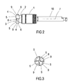
Figure 2 shows a front view of the tool of the previous figure. -
Figure 3 shows a side view of the tool ofFigure 2 . -
Figure 4 shows a cross-sectional front view of another embodiment of the tool according to the invention. - The drawings accompanying this description show three views of the preferred embodiment of the inventive tool.
- As can be seen in
Figure 1 , which shows a perspective of the preferred embodiment of the tool, the tool comprises a non-cutting main body (1), a narrowed area (2) and a cutting tip (3). The cutting tip (3) also comprises a series of cutting blades (4), each one of which is provided with a front cutting edge (5) substantially perpendicular to the longitudinal axis (7) in relation to which the tool is disposed and in relation to which said tool is designed to rotate. The cutting tip (3) also comprises a lateral cutting edge (6) substantially parallel to the longitudinal axis (7), more specifically forming an angle of between 0 and 10° with said longitudinal axis (7). The narrowed area (2) acts as an area for collecting bone. In addition, spaces (9) for receiving bone are disposed between the cutting blades (4) and connected to the narrowed area (2), preventing the blunting of the tool due to the bone debris, as explained below. - When the drilling tool is rotating, the effective cutting tip (3) is approximately rectangular, in other words it is substantially flat due to the fact that the front cutting edges (5) are substantially perpendicular to the longitudinal axis (7). This allows the tool to cut the bone in an extremely controlled manner, without the tool presenting a pointed apex that may perforate the Schneider membrane undesirably (or, in the case of its use for drilling the jawbone for the purpose of fitting an extra-short implant, prevents the tool from injuring the dental nerve). This advantage is enhanced by the fact that the bone particles produced as a result of the drilling are accumulated in the spaces (9) for receiving bone situated between the cutting blades (4), and removed towards the narrowed area (2) for retaining bone, preventing the accumulation of bone particles in the tip of the tool, which could cause the shaft tip to stop having a rectangular effective shape.
- In practice it has been shown that, given that the Schneider membrane is elastic, the rectangular effective cutting tip (3) not only does not cut the membrane but is also capable of pushing and moving the membrane without breaking it, provided that the approach with the tool is performed in a controlled manner. In other words, the tool according to the invention contributes to correctly perform a sinus lift according to the Summers technique, not only by not drilling the Schneider membrane but by moving it was well. In order to help perform the technique, the tool may be provided with some depth marks.
- In addition, as can be seen, the main body (1) is substantially cylindrical, so that said main body (1) can act as a guide during the advance of the tool inside the alveolus, while not enlarging the alveolus.
- As can be seen in
Figure 2 , which shows a front view of the tool, the narrowed area (2) is substantially conical in shape. The conical shape allows the procedure for manufacturing the piece to be simplified and makes the piece easier to clean. -
Figure 2 also shows that the lateral cutting edge (6), substantially parallel to the longitudinal axis (7), forms in one embodiment a slight angle in relation to said longitudinal axis (7). Said angle is comprised between 1 and 10°, helping center the tool during its insertion in the alveolus. Said angle also enables the advance to be controlled, as the bone that is perforated is approximately conical in shape and of a reduced size, and the slightly conical shape of the tool therefore allows a reduction in the risk of the bone being perforated incorrectly. - Additionally, as can be seen in the three figures and in particular in
Figure 3 , which shows a side view of the tool, the front cutting edges (5) of the cutting blades (4) are disposed around a central recess (8). Said central recess (8) is capable of storing a certain amount of bone particles produced as a result of the drilling, which ensures, in the event of unwanted bone particles accumulating in the area of the cutting tip during drilling, that these particles do not accumulate to form a point that becomes a cutting edge, which might break the Schneider membrane. -
Figure 4 shows a second embodiment of the tool according to the invention, the tool being shown in cross-section. As shown, in this embodiment the shaft (10) and the cutting tip (3) are connected to each other and may rotate in relation to the main body (1). This allows the tool to be used in two phases. In a first phase the tool is inserted in the alveolus, with the main body (1) being made to slide all the way along the walls of the alveolus, without the need to rotate the tool, thus making the guiding and control of the advance easier and more precise. In a second phase, when the tool has already been inserted to the necessary depth, the tool is operated to cause the rotation of the shaft (10) and the cutting tip (3), initiating the drilling, without this causing the rotation of the main body (1), thereby preventing additional and unnecessary drilling and wear of the alveolus.
Claims (7)
- Tool for drilling bone tissue, substantially disposed all the way along a longitudinal axis (7) in relation which said tool is designed to rotate, characterised in that it comprises:- a non-cutting main body (1), a shaft (10) and a cutting tip (3),- a narrowed area (2) for retaining bone, located between the cutting tip (3) and the main body (1), where- the cutting tip (3) comprises a series of cutting blades (4), each one of which is provided with a front cutting edge (5) substantially perpendicular to the longitudinal axis (7) and a lateral cutting edge (6) that forms an angle of between 0 and 10° with the longitudinal axis, where- spaces (9) for receiving bone are disposed between the cutting blades (4) and are connected to the narrowed area (2).
- Tool according to claim 1, characterised in that the main body (1) is substantially cylindrical.
- Tool according to claim 1, characterised in that the narrowed area (2) is substantially conical.
- Tool according to claim 1, characterised in that the lateral cutting edge (6) forms an angle with the longitudinal axis (7) of 0°.
- Tool according to claim 1, characterised in that the lateral cutting edge (6) forms an angle with the longitudinal axis (7) of between 1 and 10°.
- Tool according to claim 1, characterised in that the front cutting edges (5) of the cutting blades (4) are disposed around a central recess (8).
- Tool according to claim 1, characterised in that the shaft (10) and the cutting tip (3) are connected to each other and may rotate in relation to the main body (1).
Priority Applications (1)
| Application Number | Priority Date | Filing Date | Title |
|---|---|---|---|
| PL11788190T PL2620123T3 (en) | 2010-09-24 | 2011-09-16 | Tool for milling bone tissue, especially when lifting the bottom of the maxillary sinus according to the Summers technique or for placing very short implants |
Applications Claiming Priority (2)
| Application Number | Priority Date | Filing Date | Title |
|---|---|---|---|
| ES201001225A ES2355888B1 (en) | 2010-09-24 | 2010-09-24 | TOOL FOR BONE TISSUE MILLING, PARTICULARLY INDICATED FOR ELEVATION OF BREAST ACCORDING TO SUMMERS TECHNIQUE OR FOR PLACEMENT OF EXTRACORT IMPLANTS. |
| PCT/ES2011/000275 WO2012038563A1 (en) | 2010-09-24 | 2011-09-16 | Tool for milling bone tissue, especially for sinus lifting according to the summers technique or for positioning extra-short implants |
Publications (2)
| Publication Number | Publication Date |
|---|---|
| EP2620123A1 true EP2620123A1 (en) | 2013-07-31 |
| EP2620123B1 EP2620123B1 (en) | 2015-12-16 |
Family
ID=43754642
Family Applications (1)
| Application Number | Title | Priority Date | Filing Date |
|---|---|---|---|
| EP11788190.4A Active EP2620123B1 (en) | 2010-09-24 | 2011-09-16 | Tool for milling bone tissue, especially for sinus lifting according to the summers technique or for positioning extra-short implants |
Country Status (14)
| Country | Link |
|---|---|
| US (1) | US9060827B2 (en) |
| EP (1) | EP2620123B1 (en) |
| JP (1) | JP5878540B2 (en) |
| KR (1) | KR101978669B1 (en) |
| AR (1) | AR084480A1 (en) |
| BR (1) | BR112013006796B1 (en) |
| CA (1) | CA2811548C (en) |
| CO (1) | CO6650406A2 (en) |
| ES (2) | ES2355888B1 (en) |
| MX (1) | MX336312B (en) |
| PL (1) | PL2620123T3 (en) |
| RU (1) | RU2573105C2 (en) |
| TW (1) | TWI572314B (en) |
| WO (1) | WO2012038563A1 (en) |
Families Citing this family (10)
| Publication number | Priority date | Publication date | Assignee | Title |
|---|---|---|---|---|
| JP6104634B2 (en) * | 2013-02-27 | 2017-03-29 | 京セラメディカル株式会社 | Dental drill |
| JP6187862B2 (en) * | 2013-08-12 | 2017-08-30 | Bio Graft 合同会社 | Dental implant drilling system |
| KR101516949B1 (en) * | 2013-11-06 | 2015-05-04 | 주식회사 디오 | apparatus for bone flattening drill |
| ES2874641T3 (en) * | 2016-12-28 | 2021-11-05 | Straumann Holding Ag | Guide piece and milling tool system |
| KR102027336B1 (en) * | 2017-06-30 | 2019-10-01 | 주식회사 디오 | apparatus for bone flattening drill |
| CN110799133B (en) * | 2017-08-04 | 2021-11-09 | 易补骨外科有限公司 | Autologous bone grafting equipment |
| US10610243B2 (en) | 2017-10-09 | 2020-04-07 | Acumed Llc | System and method for installing a bicortical implant in bone |
| CN110811756A (en) * | 2019-11-22 | 2020-02-21 | 武汉大学 | Machine drill bit for maxillary sinus internal lifting operation |
| TWI797619B (en) * | 2021-05-12 | 2023-04-01 | 炳碩生醫股份有限公司 | Surgical drill and orthopedic surgery system |
| KR102544369B1 (en) * | 2021-05-31 | 2023-06-19 | 주식회사 덴티스 | Sinus drilling instrument |
Family Cites Families (22)
| Publication number | Priority date | Publication date | Assignee | Title |
|---|---|---|---|---|
| US4285618A (en) * | 1979-10-12 | 1981-08-25 | Shanley Stephen E Jr | Rotary milling cutter |
| SU1718851A1 (en) * | 1989-12-11 | 1992-03-15 | Ж.Н.Кадыров, А.Ж.Абдрахманов, А.С.Маслий и С.Н.Кадырова | Surgical drill |
| FR2676639A1 (en) * | 1991-05-21 | 1992-11-27 | Peltier Patrick | IMPROVEMENTS ON HELICAL FORESTS FOR BONE SURGERY, PARTICULARLY FOR DENTAL SURGERY. |
| FR2702164B1 (en) * | 1993-03-01 | 1995-06-02 | Sylvain Bordes | Drill for the installation of a dental implant in particular. |
| EP0700272B1 (en) * | 1993-05-27 | 1999-01-07 | Howmedica Inc. | Flexible medullary reaming system |
| DE29606335U1 (en) * | 1996-04-01 | 1996-07-04 | Nowak, Marcus, Dr., 14195 Berlin | Oral surgical instrument (osteotome) to create openings in the jaw bone for inserting implants |
| JPH1043193A (en) * | 1996-08-07 | 1998-02-17 | Urawa Kogyo Kk | Cutter for bone cutting |
| EP0965308B1 (en) * | 1998-06-17 | 2007-08-01 | Precimed S.A. | Surgical reamer |
| US6146476A (en) * | 1999-02-08 | 2000-11-14 | Alvord-Polk, Inc. | Laser-clad composite cutting tool and method |
| US6319005B1 (en) | 2000-09-18 | 2001-11-20 | Biolok International Inc. | Dental irrigation drill with internal anti-backwash baffle |
| US6863529B2 (en) * | 2001-05-18 | 2005-03-08 | Biohorizons Implant Systems, Inc. | Dental drill system and method of use |
| AU2003236173A1 (en) * | 2002-04-04 | 2003-10-20 | Akira Kitamura | Drill device for implanting |
| ES2235578B2 (en) * | 2002-11-18 | 2007-08-16 | Eduardo Anitua Aldecoa | SET OF MANUAL OR MOTORIZED DRIVING INSTRUMENTS TO FACILITATE THE SETTING OF DENTAL IMPLANTS. |
| US8025662B2 (en) * | 2004-03-25 | 2011-09-27 | Symmetry Medical, Inc. | Bidirectional reaming cutter |
| KR100630304B1 (en) * | 2006-04-04 | 2006-10-02 | 안상훈 | Implant Expansion Machine |
| US7837707B2 (en) * | 2006-12-31 | 2010-11-23 | Yamada Jason M | Internal procedure for closing sinus membrane perforations |
| ITRE20070053A1 (en) * | 2007-04-12 | 2008-10-13 | Cgm Spa | "BONE SURGICAL INSTRUMENT" |
| KR100924092B1 (en) * | 2007-11-30 | 2009-11-02 | 김영기 | Implant Expansion Machine |
| KR100838942B1 (en) * | 2008-02-04 | 2008-06-16 | 허영구 | Maxillary sinus membrane drill |
| KR100981716B1 (en) * | 2008-04-04 | 2010-09-13 | 주식회사 메가젠임플란트 | Drill Tool for Lifting Sinus |
| WO2009151275A2 (en) * | 2008-06-13 | 2009-12-17 | 주식회사 메가젠임플란트 | Drill tool for lifting sinus |
| DE102010018245A1 (en) | 2010-04-23 | 2011-10-27 | Herbert R. Hatzlhoffer | Surgical tool, in particular for drilling bone for the insertion of a dental implant |
-
2010
- 2010-09-24 ES ES201001225A patent/ES2355888B1/en not_active Expired - Fee Related
-
2011
- 2011-09-16 JP JP2013529684A patent/JP5878540B2/en active Active
- 2011-09-16 EP EP11788190.4A patent/EP2620123B1/en active Active
- 2011-09-16 RU RU2013112932/14A patent/RU2573105C2/en active
- 2011-09-16 PL PL11788190T patent/PL2620123T3/en unknown
- 2011-09-16 KR KR1020137006944A patent/KR101978669B1/en not_active Expired - Fee Related
- 2011-09-16 BR BR112013006796-9A patent/BR112013006796B1/en not_active IP Right Cessation
- 2011-09-16 WO PCT/ES2011/000275 patent/WO2012038563A1/en not_active Ceased
- 2011-09-16 CA CA2811548A patent/CA2811548C/en active Active
- 2011-09-16 ES ES11788190.4T patent/ES2564356T3/en active Active
- 2011-09-16 MX MX2013002355A patent/MX336312B/en unknown
- 2011-09-20 TW TW100133686A patent/TWI572314B/en not_active IP Right Cessation
- 2011-09-21 US US13/238,574 patent/US9060827B2/en active Active
- 2011-09-23 AR ARP110103493A patent/AR084480A1/en unknown
-
2013
- 2013-03-22 CO CO13057539A patent/CO6650406A2/en not_active Application Discontinuation
Non-Patent Citations (1)
| Title |
|---|
| See references of WO2012038563A1 * |
Also Published As
| Publication number | Publication date |
|---|---|
| BR112013006796A2 (en) | 2016-07-12 |
| TW201212871A (en) | 2012-04-01 |
| KR20130097764A (en) | 2013-09-03 |
| WO2012038563A8 (en) | 2012-06-14 |
| MX2013002355A (en) | 2013-05-22 |
| KR101978669B1 (en) | 2019-05-15 |
| RU2013112932A (en) | 2014-10-27 |
| CO6650406A2 (en) | 2013-04-15 |
| AR084480A1 (en) | 2013-05-22 |
| ES2564356T3 (en) | 2016-03-22 |
| US20120078257A1 (en) | 2012-03-29 |
| BR112013006796B1 (en) | 2020-09-08 |
| US9060827B2 (en) | 2015-06-23 |
| RU2573105C2 (en) | 2016-01-20 |
| ES2355888B1 (en) | 2012-02-24 |
| CA2811548A1 (en) | 2012-03-29 |
| ES2355888A1 (en) | 2011-04-01 |
| JP5878540B2 (en) | 2016-03-08 |
| JP2013537825A (en) | 2013-10-07 |
| MX336312B (en) | 2016-01-13 |
| TWI572314B (en) | 2017-03-01 |
| EP2620123B1 (en) | 2015-12-16 |
| WO2012038563A1 (en) | 2012-03-29 |
| CA2811548C (en) | 2018-04-24 |
| PL2620123T3 (en) | 2016-06-30 |
Similar Documents
| Publication | Publication Date | Title |
|---|---|---|
| US9060827B2 (en) | Tool for drilling bone tissue, particularly suitable for performing a sinus lift according to the summers technique or for the fitting of extra-short implants | |
| KR100924092B1 (en) | Implant Expansion Machine | |
| CN101808592B (en) | Drill for sinus membrane lift | |
| KR100981717B1 (en) | Maxillary sinus drill drill tool | |
| WO2017091497A1 (en) | Implant placement trephine, prepackaged and sized implant / trephine kit, and methods of use | |
| US20120045731A1 (en) | Guided pin system trephine drill | |
| US20230404705A1 (en) | Guided implant drill system and methods of use | |
| EP3777750B1 (en) | Drill bit | |
| KR100981718B1 (en) | Implant Drills | |
| JP2013521090A (en) | Implant extraction method and coronal saw drill bit enabling extraction | |
| KR101500126B1 (en) | A punching device that digs tissue of gum | |
| KR101170895B1 (en) | Windows opener for lateral sinus graft surgical operation | |
| US12076212B1 (en) | Internal sinus lifting drill set | |
| EP2689742A2 (en) | Bone carving tool for creating convex ridge for inner border of initial hole for placement of implant hole | |
| US20110294092A1 (en) | System and method for dental implant surgery | |
| WO2024105619A1 (en) | Self-osteotome dental implant and orthopedic fastener | |
| WO2015087321A1 (en) | Sinus lift apparatus and method | |
| WO2025238539A1 (en) | Dental implant | |
| WO2012104459A1 (en) | Device for dental implant procedures |
Legal Events
| Date | Code | Title | Description |
|---|---|---|---|
| PUAI | Public reference made under article 153(3) epc to a published international application that has entered the european phase |
Free format text: ORIGINAL CODE: 0009012 |
|
| 17P | Request for examination filed |
Effective date: 20130315 |
|
| AK | Designated contracting states |
Kind code of ref document: A1 Designated state(s): AL AT BE BG CH CY CZ DE DK EE ES FI FR GB GR HR HU IE IS IT LI LT LU LV MC MK MT NL NO PL PT RO RS SE SI SK SM TR |
|
| DAX | Request for extension of the european patent (deleted) | ||
| GRAP | Despatch of communication of intention to grant a patent |
Free format text: ORIGINAL CODE: EPIDOSNIGR1 |
|
| INTG | Intention to grant announced |
Effective date: 20150625 |
|
| GRAS | Grant fee paid |
Free format text: ORIGINAL CODE: EPIDOSNIGR3 |
|
| GRAA | (expected) grant |
Free format text: ORIGINAL CODE: 0009210 |
|
| AK | Designated contracting states |
Kind code of ref document: B1 Designated state(s): AL AT BE BG CH CY CZ DE DK EE ES FI FR GB GR HR HU IE IS IT LI LT LU LV MC MK MT NL NO PL PT RO RS SE SI SK SM TR |
|
| REG | Reference to a national code |
Ref country code: GB Ref legal event code: FG4D |
|
| REG | Reference to a national code |
Ref country code: CH Ref legal event code: EP |
|
| REG | Reference to a national code |
Ref country code: IE Ref legal event code: FG4D |
|
| REG | Reference to a national code |
Ref country code: AT Ref legal event code: REF Ref document number: 765138 Country of ref document: AT Kind code of ref document: T Effective date: 20160115 |
|
| REG | Reference to a national code |
Ref country code: DE Ref legal event code: R096 Ref document number: 602011022105 Country of ref document: DE |
|
| REG | Reference to a national code |
Ref country code: CH Ref legal event code: NV Representative=s name: MOINAS AND SAVOYE SARL, CH |
|
| REG | Reference to a national code |
Ref country code: SE Ref legal event code: TRGR Ref country code: ES Ref legal event code: FG2A Ref document number: 2564356 Country of ref document: ES Kind code of ref document: T3 Effective date: 20160322 |
|
| REG | Reference to a national code |
Ref country code: PT Ref legal event code: SC4A Free format text: AVAILABILITY OF NATIONAL TRANSLATION Effective date: 20160222 |
|
| REG | Reference to a national code |
Ref country code: NL Ref legal event code: FP |
|
| REG | Reference to a national code |
Ref country code: NO Ref legal event code: T2 Effective date: 20151216 |
|
| REG | Reference to a national code |
Ref country code: LT Ref legal event code: MG4D |
|
| PG25 | Lapsed in a contracting state [announced via postgrant information from national office to epo] |
Ref country code: LT Free format text: LAPSE BECAUSE OF FAILURE TO SUBMIT A TRANSLATION OF THE DESCRIPTION OR TO PAY THE FEE WITHIN THE PRESCRIBED TIME-LIMIT Effective date: 20151216 Ref country code: HR Free format text: LAPSE BECAUSE OF FAILURE TO SUBMIT A TRANSLATION OF THE DESCRIPTION OR TO PAY THE FEE WITHIN THE PRESCRIBED TIME-LIMIT Effective date: 20151216 |
|
| PG25 | Lapsed in a contracting state [announced via postgrant information from national office to epo] |
Ref country code: RS Free format text: LAPSE BECAUSE OF FAILURE TO SUBMIT A TRANSLATION OF THE DESCRIPTION OR TO PAY THE FEE WITHIN THE PRESCRIBED TIME-LIMIT Effective date: 20151216 Ref country code: LV Free format text: LAPSE BECAUSE OF FAILURE TO SUBMIT A TRANSLATION OF THE DESCRIPTION OR TO PAY THE FEE WITHIN THE PRESCRIBED TIME-LIMIT Effective date: 20151216 |
|
| REG | Reference to a national code |
Ref country code: GR Ref legal event code: EP Ref document number: 20160400482 Country of ref document: GR Effective date: 20160505 |
|
| PG25 | Lapsed in a contracting state [announced via postgrant information from national office to epo] |
Ref country code: CZ Free format text: LAPSE BECAUSE OF FAILURE TO SUBMIT A TRANSLATION OF THE DESCRIPTION OR TO PAY THE FEE WITHIN THE PRESCRIBED TIME-LIMIT Effective date: 20151216 |
|
| PG25 | Lapsed in a contracting state [announced via postgrant information from national office to epo] |
Ref country code: SM Free format text: LAPSE BECAUSE OF FAILURE TO SUBMIT A TRANSLATION OF THE DESCRIPTION OR TO PAY THE FEE WITHIN THE PRESCRIBED TIME-LIMIT Effective date: 20151216 Ref country code: EE Free format text: LAPSE BECAUSE OF FAILURE TO SUBMIT A TRANSLATION OF THE DESCRIPTION OR TO PAY THE FEE WITHIN THE PRESCRIBED TIME-LIMIT Effective date: 20151216 Ref country code: RO Free format text: LAPSE BECAUSE OF FAILURE TO SUBMIT A TRANSLATION OF THE DESCRIPTION OR TO PAY THE FEE WITHIN THE PRESCRIBED TIME-LIMIT Effective date: 20151216 Ref country code: SK Free format text: LAPSE BECAUSE OF FAILURE TO SUBMIT A TRANSLATION OF THE DESCRIPTION OR TO PAY THE FEE WITHIN THE PRESCRIBED TIME-LIMIT Effective date: 20151216 Ref country code: IS Free format text: LAPSE BECAUSE OF FAILURE TO SUBMIT A TRANSLATION OF THE DESCRIPTION OR TO PAY THE FEE WITHIN THE PRESCRIBED TIME-LIMIT Effective date: 20160416 |
|
| REG | Reference to a national code |
Ref country code: DE Ref legal event code: R097 Ref document number: 602011022105 Country of ref document: DE |
|
| REG | Reference to a national code |
Ref country code: FR Ref legal event code: PLFP Year of fee payment: 6 |
|
| PLBE | No opposition filed within time limit |
Free format text: ORIGINAL CODE: 0009261 |
|
| STAA | Information on the status of an ep patent application or granted ep patent |
Free format text: STATUS: NO OPPOSITION FILED WITHIN TIME LIMIT |
|
| PG25 | Lapsed in a contracting state [announced via postgrant information from national office to epo] |
Ref country code: DK Free format text: LAPSE BECAUSE OF FAILURE TO SUBMIT A TRANSLATION OF THE DESCRIPTION OR TO PAY THE FEE WITHIN THE PRESCRIBED TIME-LIMIT Effective date: 20151216 |
|
| 26N | No opposition filed |
Effective date: 20160919 |
|
| PG25 | Lapsed in a contracting state [announced via postgrant information from national office to epo] |
Ref country code: SI Free format text: LAPSE BECAUSE OF FAILURE TO SUBMIT A TRANSLATION OF THE DESCRIPTION OR TO PAY THE FEE WITHIN THE PRESCRIBED TIME-LIMIT Effective date: 20151216 |
|
| PG25 | Lapsed in a contracting state [announced via postgrant information from national office to epo] |
Ref country code: MC Free format text: LAPSE BECAUSE OF FAILURE TO SUBMIT A TRANSLATION OF THE DESCRIPTION OR TO PAY THE FEE WITHIN THE PRESCRIBED TIME-LIMIT Effective date: 20151216 |
|
| REG | Reference to a national code |
Ref country code: FR Ref legal event code: PLFP Year of fee payment: 7 |
|
| PG25 | Lapsed in a contracting state [announced via postgrant information from national office to epo] |
Ref country code: CY Free format text: LAPSE BECAUSE OF FAILURE TO SUBMIT A TRANSLATION OF THE DESCRIPTION OR TO PAY THE FEE WITHIN THE PRESCRIBED TIME-LIMIT Effective date: 20151216 Ref country code: HU Free format text: LAPSE BECAUSE OF FAILURE TO SUBMIT A TRANSLATION OF THE DESCRIPTION OR TO PAY THE FEE WITHIN THE PRESCRIBED TIME-LIMIT; INVALID AB INITIO Effective date: 20110916 |
|
| PG25 | Lapsed in a contracting state [announced via postgrant information from national office to epo] |
Ref country code: MK Free format text: LAPSE BECAUSE OF FAILURE TO SUBMIT A TRANSLATION OF THE DESCRIPTION OR TO PAY THE FEE WITHIN THE PRESCRIBED TIME-LIMIT Effective date: 20151216 Ref country code: MT Free format text: LAPSE BECAUSE OF NON-PAYMENT OF DUE FEES Effective date: 20160930 |
|
| PG25 | Lapsed in a contracting state [announced via postgrant information from national office to epo] |
Ref country code: BG Free format text: LAPSE BECAUSE OF FAILURE TO SUBMIT A TRANSLATION OF THE DESCRIPTION OR TO PAY THE FEE WITHIN THE PRESCRIBED TIME-LIMIT Effective date: 20151216 |
|
| REG | Reference to a national code |
Ref country code: FR Ref legal event code: PLFP Year of fee payment: 8 |
|
| PG25 | Lapsed in a contracting state [announced via postgrant information from national office to epo] |
Ref country code: AL Free format text: LAPSE BECAUSE OF FAILURE TO SUBMIT A TRANSLATION OF THE DESCRIPTION OR TO PAY THE FEE WITHIN THE PRESCRIBED TIME-LIMIT Effective date: 20151216 |
|
| REG | Reference to a national code |
Ref country code: AT Ref legal event code: UEP Ref document number: 765138 Country of ref document: AT Kind code of ref document: T Effective date: 20151216 |
|
| PGFP | Annual fee paid to national office [announced via postgrant information from national office to epo] |
Ref country code: TR Payment date: 20200903 Year of fee payment: 10 |
|
| P01 | Opt-out of the competence of the unified patent court (upc) registered |
Effective date: 20230605 |
|
| PG25 | Lapsed in a contracting state [announced via postgrant information from national office to epo] |
Ref country code: TR Free format text: LAPSE BECAUSE OF NON-PAYMENT OF DUE FEES Effective date: 20210916 |
|
| REG | Reference to a national code |
Ref country code: CH Ref legal event code: U11 Free format text: ST27 STATUS EVENT CODE: U-0-0-U10-U11 (AS PROVIDED BY THE NATIONAL OFFICE) Effective date: 20251001 |
|
| PGFP | Annual fee paid to national office [announced via postgrant information from national office to epo] |
Ref country code: FI Payment date: 20250925 Year of fee payment: 15 Ref country code: PT Payment date: 20250903 Year of fee payment: 15 |
|
| PGFP | Annual fee paid to national office [announced via postgrant information from national office to epo] |
Ref country code: DE Payment date: 20250929 Year of fee payment: 15 |
|
| PGFP | Annual fee paid to national office [announced via postgrant information from national office to epo] |
Ref country code: NO Payment date: 20250929 Year of fee payment: 15 Ref country code: GR Payment date: 20250926 Year of fee payment: 15 |
|
| PGFP | Annual fee paid to national office [announced via postgrant information from national office to epo] |
Ref country code: PL Payment date: 20250903 Year of fee payment: 15 Ref country code: LU Payment date: 20250929 Year of fee payment: 15 Ref country code: IT Payment date: 20250919 Year of fee payment: 15 Ref country code: NL Payment date: 20250926 Year of fee payment: 15 |
|
| PGFP | Annual fee paid to national office [announced via postgrant information from national office to epo] |
Ref country code: BE Payment date: 20250929 Year of fee payment: 15 Ref country code: GB Payment date: 20250929 Year of fee payment: 15 |
|
| PGFP | Annual fee paid to national office [announced via postgrant information from national office to epo] |
Ref country code: FR Payment date: 20250925 Year of fee payment: 15 Ref country code: AT Payment date: 20250929 Year of fee payment: 15 |
|
| PGFP | Annual fee paid to national office [announced via postgrant information from national office to epo] |
Ref country code: SE Payment date: 20250927 Year of fee payment: 15 |
|
| PGFP | Annual fee paid to national office [announced via postgrant information from national office to epo] |
Ref country code: IE Payment date: 20250929 Year of fee payment: 15 |
|
| PGFP | Annual fee paid to national office [announced via postgrant information from national office to epo] |
Ref country code: CH Payment date: 20251001 Year of fee payment: 15 |
|
| PGFP | Annual fee paid to national office [announced via postgrant information from national office to epo] |
Ref country code: ES Payment date: 20251001 Year of fee payment: 15 |