EP2619892B1 - Systems for charging an energy store, and method for operating the charging systems - Google Patents
Systems for charging an energy store, and method for operating the charging systems Download PDFInfo
- Publication number
- EP2619892B1 EP2619892B1 EP11748399.0A EP11748399A EP2619892B1 EP 2619892 B1 EP2619892 B1 EP 2619892B1 EP 11748399 A EP11748399 A EP 11748399A EP 2619892 B1 EP2619892 B1 EP 2619892B1
- Authority
- EP
- European Patent Office
- Prior art keywords
- energy storage
- charging
- energy
- storage cells
- charging device
- Prior art date
- Legal status (The legal status is an assumption and is not a legal conclusion. Google has not performed a legal analysis and makes no representation as to the accuracy of the status listed.)
- Active
Links
- 238000000034 method Methods 0.000 title claims description 10
- 238000004146 energy storage Methods 0.000 claims description 74
- 210000000352 storage cell Anatomy 0.000 claims description 48
- 230000008878 coupling Effects 0.000 claims description 41
- 238000010168 coupling process Methods 0.000 claims description 41
- 238000005859 coupling reaction Methods 0.000 claims description 41
- 210000004027 cell Anatomy 0.000 description 11
- 238000004804 winding Methods 0.000 description 10
- 230000008569 process Effects 0.000 description 5
- 230000000903 blocking effect Effects 0.000 description 2
- 238000005516 engineering process Methods 0.000 description 2
- 239000004065 semiconductor Substances 0.000 description 2
- 230000004913 activation Effects 0.000 description 1
- 230000006978 adaptation Effects 0.000 description 1
- 238000010586 diagram Methods 0.000 description 1
- 230000000694 effects Effects 0.000 description 1
- 230000005669 field effect Effects 0.000 description 1
- 238000009434 installation Methods 0.000 description 1
- 229910044991 metal oxide Inorganic materials 0.000 description 1
- 150000004706 metal oxides Chemical class 0.000 description 1
Images

Classifications
-
- B—PERFORMING OPERATIONS; TRANSPORTING
- B60—VEHICLES IN GENERAL
- B60L—PROPULSION OF ELECTRICALLY-PROPELLED VEHICLES; SUPPLYING ELECTRIC POWER FOR AUXILIARY EQUIPMENT OF ELECTRICALLY-PROPELLED VEHICLES; ELECTRODYNAMIC BRAKE SYSTEMS FOR VEHICLES IN GENERAL; MAGNETIC SUSPENSION OR LEVITATION FOR VEHICLES; MONITORING OPERATING VARIABLES OF ELECTRICALLY-PROPELLED VEHICLES; ELECTRIC SAFETY DEVICES FOR ELECTRICALLY-PROPELLED VEHICLES
- B60L53/00—Methods of charging batteries, specially adapted for electric vehicles; Charging stations or on-board charging equipment therefor; Exchange of energy storage elements in electric vehicles
- B60L53/10—Methods of charging batteries, specially adapted for electric vehicles; Charging stations or on-board charging equipment therefor; Exchange of energy storage elements in electric vehicles characterised by the energy transfer between the charging station and the vehicle
- B60L53/14—Conductive energy transfer
-
- B—PERFORMING OPERATIONS; TRANSPORTING
- B60—VEHICLES IN GENERAL
- B60L—PROPULSION OF ELECTRICALLY-PROPELLED VEHICLES; SUPPLYING ELECTRIC POWER FOR AUXILIARY EQUIPMENT OF ELECTRICALLY-PROPELLED VEHICLES; ELECTRODYNAMIC BRAKE SYSTEMS FOR VEHICLES IN GENERAL; MAGNETIC SUSPENSION OR LEVITATION FOR VEHICLES; MONITORING OPERATING VARIABLES OF ELECTRICALLY-PROPELLED VEHICLES; ELECTRIC SAFETY DEVICES FOR ELECTRICALLY-PROPELLED VEHICLES
- B60L53/00—Methods of charging batteries, specially adapted for electric vehicles; Charging stations or on-board charging equipment therefor; Exchange of energy storage elements in electric vehicles
- B60L53/20—Methods of charging batteries, specially adapted for electric vehicles; Charging stations or on-board charging equipment therefor; Exchange of energy storage elements in electric vehicles characterised by converters located in the vehicle
- B60L53/24—Using the vehicle's propulsion converter for charging
-
- B—PERFORMING OPERATIONS; TRANSPORTING
- B60—VEHICLES IN GENERAL
- B60L—PROPULSION OF ELECTRICALLY-PROPELLED VEHICLES; SUPPLYING ELECTRIC POWER FOR AUXILIARY EQUIPMENT OF ELECTRICALLY-PROPELLED VEHICLES; ELECTRODYNAMIC BRAKE SYSTEMS FOR VEHICLES IN GENERAL; MAGNETIC SUSPENSION OR LEVITATION FOR VEHICLES; MONITORING OPERATING VARIABLES OF ELECTRICALLY-PROPELLED VEHICLES; ELECTRIC SAFETY DEVICES FOR ELECTRICALLY-PROPELLED VEHICLES
- B60L58/00—Methods or circuit arrangements for monitoring or controlling batteries or fuel cells, specially adapted for electric vehicles
- B60L58/10—Methods or circuit arrangements for monitoring or controlling batteries or fuel cells, specially adapted for electric vehicles for monitoring or controlling batteries
- B60L58/18—Methods or circuit arrangements for monitoring or controlling batteries or fuel cells, specially adapted for electric vehicles for monitoring or controlling batteries of two or more battery modules
- B60L58/21—Methods or circuit arrangements for monitoring or controlling batteries or fuel cells, specially adapted for electric vehicles for monitoring or controlling batteries of two or more battery modules having the same nominal voltage
-
- H—ELECTRICITY
- H02—GENERATION; CONVERSION OR DISTRIBUTION OF ELECTRIC POWER
- H02J—CIRCUIT ARRANGEMENTS OR SYSTEMS FOR SUPPLYING OR DISTRIBUTING ELECTRIC POWER; SYSTEMS FOR STORING ELECTRIC ENERGY
- H02J7/00—Circuit arrangements for charging or depolarising batteries or for supplying loads from batteries
- H02J7/0013—Circuit arrangements for charging or depolarising batteries or for supplying loads from batteries acting upon several batteries simultaneously or sequentially
- H02J7/0014—Circuits for equalisation of charge between batteries
- H02J7/0016—Circuits for equalisation of charge between batteries using shunting, discharge or bypass circuits
-
- H—ELECTRICITY
- H02—GENERATION; CONVERSION OR DISTRIBUTION OF ELECTRIC POWER
- H02J—CIRCUIT ARRANGEMENTS OR SYSTEMS FOR SUPPLYING OR DISTRIBUTING ELECTRIC POWER; SYSTEMS FOR STORING ELECTRIC ENERGY
- H02J7/00—Circuit arrangements for charging or depolarising batteries or for supplying loads from batteries
- H02J7/0013—Circuit arrangements for charging or depolarising batteries or for supplying loads from batteries acting upon several batteries simultaneously or sequentially
- H02J7/0014—Circuits for equalisation of charge between batteries
- H02J7/0019—Circuits for equalisation of charge between batteries using switched or multiplexed charge circuits
-
- H—ELECTRICITY
- H02—GENERATION; CONVERSION OR DISTRIBUTION OF ELECTRIC POWER
- H02J—CIRCUIT ARRANGEMENTS OR SYSTEMS FOR SUPPLYING OR DISTRIBUTING ELECTRIC POWER; SYSTEMS FOR STORING ELECTRIC ENERGY
- H02J7/00—Circuit arrangements for charging or depolarising batteries or for supplying loads from batteries
- H02J7/0013—Circuit arrangements for charging or depolarising batteries or for supplying loads from batteries acting upon several batteries simultaneously or sequentially
- H02J7/0024—Parallel/serial switching of connection of batteries to charge or load circuit
-
- H—ELECTRICITY
- H02—GENERATION; CONVERSION OR DISTRIBUTION OF ELECTRIC POWER
- H02J—CIRCUIT ARRANGEMENTS OR SYSTEMS FOR SUPPLYING OR DISTRIBUTING ELECTRIC POWER; SYSTEMS FOR STORING ELECTRIC ENERGY
- H02J7/00—Circuit arrangements for charging or depolarising batteries or for supplying loads from batteries
- H02J7/0013—Circuit arrangements for charging or depolarising batteries or for supplying loads from batteries acting upon several batteries simultaneously or sequentially
- H02J7/0025—Sequential battery discharge in systems with a plurality of batteries
-
- H—ELECTRICITY
- H02—GENERATION; CONVERSION OR DISTRIBUTION OF ELECTRIC POWER
- H02J—CIRCUIT ARRANGEMENTS OR SYSTEMS FOR SUPPLYING OR DISTRIBUTING ELECTRIC POWER; SYSTEMS FOR STORING ELECTRIC ENERGY
- H02J7/00—Circuit arrangements for charging or depolarising batteries or for supplying loads from batteries
- H02J7/14—Circuit arrangements for charging or depolarising batteries or for supplying loads from batteries for charging batteries from dynamo-electric generators driven at varying speed, e.g. on vehicle
- H02J7/1469—Regulation of the charging current or voltage otherwise than by variation of field
- H02J7/1492—Regulation of the charging current or voltage otherwise than by variation of field by means of controlling devices between the generator output and the battery
-
- H—ELECTRICITY
- H02—GENERATION; CONVERSION OR DISTRIBUTION OF ELECTRIC POWER
- H02M—APPARATUS FOR CONVERSION BETWEEN AC AND AC, BETWEEN AC AND DC, OR BETWEEN DC AND DC, AND FOR USE WITH MAINS OR SIMILAR POWER SUPPLY SYSTEMS; CONVERSION OF DC OR AC INPUT POWER INTO SURGE OUTPUT POWER; CONTROL OR REGULATION THEREOF
- H02M7/00—Conversion of AC power input into DC power output; Conversion of DC power input into AC power output
- H02M7/42—Conversion of DC power input into AC power output without possibility of reversal
- H02M7/44—Conversion of DC power input into AC power output without possibility of reversal by static converters
- H02M7/48—Conversion of DC power input into AC power output without possibility of reversal by static converters using discharge tubes with control electrode or semiconductor devices with control electrode
- H02M7/483—Converters with outputs that each can have more than two voltages levels
- H02M7/49—Combination of the output voltage waveforms of a plurality of converters
-
- H—ELECTRICITY
- H02—GENERATION; CONVERSION OR DISTRIBUTION OF ELECTRIC POWER
- H02P—CONTROL OR REGULATION OF ELECTRIC MOTORS, ELECTRIC GENERATORS OR DYNAMO-ELECTRIC CONVERTERS; CONTROLLING TRANSFORMERS, REACTORS OR CHOKE COILS
- H02P31/00—Arrangements for regulating or controlling electric motors not provided for in groups H02P1/00 - H02P5/00, H02P7/00 or H02P21/00 - H02P29/00
-
- B—PERFORMING OPERATIONS; TRANSPORTING
- B60—VEHICLES IN GENERAL
- B60L—PROPULSION OF ELECTRICALLY-PROPELLED VEHICLES; SUPPLYING ELECTRIC POWER FOR AUXILIARY EQUIPMENT OF ELECTRICALLY-PROPELLED VEHICLES; ELECTRODYNAMIC BRAKE SYSTEMS FOR VEHICLES IN GENERAL; MAGNETIC SUSPENSION OR LEVITATION FOR VEHICLES; MONITORING OPERATING VARIABLES OF ELECTRICALLY-PROPELLED VEHICLES; ELECTRIC SAFETY DEVICES FOR ELECTRICALLY-PROPELLED VEHICLES
- B60L2220/00—Electrical machine types; Structures or applications thereof
- B60L2220/50—Structural details of electrical machines
- B60L2220/54—Windings for different functions
-
- H—ELECTRICITY
- H02—GENERATION; CONVERSION OR DISTRIBUTION OF ELECTRIC POWER
- H02J—CIRCUIT ARRANGEMENTS OR SYSTEMS FOR SUPPLYING OR DISTRIBUTING ELECTRIC POWER; SYSTEMS FOR STORING ELECTRIC ENERGY
- H02J2207/00—Indexing scheme relating to details of circuit arrangements for charging or depolarising batteries or for supplying loads from batteries
- H02J2207/20—Charging or discharging characterised by the power electronics converter
-
- H—ELECTRICITY
- H02—GENERATION; CONVERSION OR DISTRIBUTION OF ELECTRIC POWER
- H02J—CIRCUIT ARRANGEMENTS OR SYSTEMS FOR SUPPLYING OR DISTRIBUTING ELECTRIC POWER; SYSTEMS FOR STORING ELECTRIC ENERGY
- H02J2207/00—Indexing scheme relating to details of circuit arrangements for charging or depolarising batteries or for supplying loads from batteries
- H02J2207/40—Indexing scheme relating to details of circuit arrangements for charging or depolarising batteries or for supplying loads from batteries adapted for charging from various sources, e.g. AC, DC or multivoltage
-
- H—ELECTRICITY
- H02—GENERATION; CONVERSION OR DISTRIBUTION OF ELECTRIC POWER
- H02J—CIRCUIT ARRANGEMENTS OR SYSTEMS FOR SUPPLYING OR DISTRIBUTING ELECTRIC POWER; SYSTEMS FOR STORING ELECTRIC ENERGY
- H02J2300/00—Systems for supplying or distributing electric power characterised by decentralized, dispersed, or local generation
- H02J2300/20—The dispersed energy generation being of renewable origin
- H02J2300/28—The renewable source being wind energy
-
- H—ELECTRICITY
- H02—GENERATION; CONVERSION OR DISTRIBUTION OF ELECTRIC POWER
- H02J—CIRCUIT ARRANGEMENTS OR SYSTEMS FOR SUPPLYING OR DISTRIBUTING ELECTRIC POWER; SYSTEMS FOR STORING ELECTRIC ENERGY
- H02J2310/00—The network for supplying or distributing electric power characterised by its spatial reach or by the load
- H02J2310/40—The network being an on-board power network, i.e. within a vehicle
- H02J2310/48—The network being an on-board power network, i.e. within a vehicle for electric vehicles [EV] or hybrid vehicles [HEV]
-
- Y—GENERAL TAGGING OF NEW TECHNOLOGICAL DEVELOPMENTS; GENERAL TAGGING OF CROSS-SECTIONAL TECHNOLOGIES SPANNING OVER SEVERAL SECTIONS OF THE IPC; TECHNICAL SUBJECTS COVERED BY FORMER USPC CROSS-REFERENCE ART COLLECTIONS [XRACs] AND DIGESTS
- Y02—TECHNOLOGIES OR APPLICATIONS FOR MITIGATION OR ADAPTATION AGAINST CLIMATE CHANGE
- Y02E—REDUCTION OF GREENHOUSE GAS [GHG] EMISSIONS, RELATED TO ENERGY GENERATION, TRANSMISSION OR DISTRIBUTION
- Y02E10/00—Energy generation through renewable energy sources
- Y02E10/70—Wind energy
- Y02E10/76—Power conversion electric or electronic aspects
-
- Y—GENERAL TAGGING OF NEW TECHNOLOGICAL DEVELOPMENTS; GENERAL TAGGING OF CROSS-SECTIONAL TECHNOLOGIES SPANNING OVER SEVERAL SECTIONS OF THE IPC; TECHNICAL SUBJECTS COVERED BY FORMER USPC CROSS-REFERENCE ART COLLECTIONS [XRACs] AND DIGESTS
- Y02—TECHNOLOGIES OR APPLICATIONS FOR MITIGATION OR ADAPTATION AGAINST CLIMATE CHANGE
- Y02T—CLIMATE CHANGE MITIGATION TECHNOLOGIES RELATED TO TRANSPORTATION
- Y02T10/00—Road transport of goods or passengers
- Y02T10/60—Other road transportation technologies with climate change mitigation effect
- Y02T10/64—Electric machine technologies in electromobility
-
- Y—GENERAL TAGGING OF NEW TECHNOLOGICAL DEVELOPMENTS; GENERAL TAGGING OF CROSS-SECTIONAL TECHNOLOGIES SPANNING OVER SEVERAL SECTIONS OF THE IPC; TECHNICAL SUBJECTS COVERED BY FORMER USPC CROSS-REFERENCE ART COLLECTIONS [XRACs] AND DIGESTS
- Y02—TECHNOLOGIES OR APPLICATIONS FOR MITIGATION OR ADAPTATION AGAINST CLIMATE CHANGE
- Y02T—CLIMATE CHANGE MITIGATION TECHNOLOGIES RELATED TO TRANSPORTATION
- Y02T10/00—Road transport of goods or passengers
- Y02T10/60—Other road transportation technologies with climate change mitigation effect
- Y02T10/70—Energy storage systems for electromobility, e.g. batteries
-
- Y—GENERAL TAGGING OF NEW TECHNOLOGICAL DEVELOPMENTS; GENERAL TAGGING OF CROSS-SECTIONAL TECHNOLOGIES SPANNING OVER SEVERAL SECTIONS OF THE IPC; TECHNICAL SUBJECTS COVERED BY FORMER USPC CROSS-REFERENCE ART COLLECTIONS [XRACs] AND DIGESTS
- Y02—TECHNOLOGIES OR APPLICATIONS FOR MITIGATION OR ADAPTATION AGAINST CLIMATE CHANGE
- Y02T—CLIMATE CHANGE MITIGATION TECHNOLOGIES RELATED TO TRANSPORTATION
- Y02T10/00—Road transport of goods or passengers
- Y02T10/60—Other road transportation technologies with climate change mitigation effect
- Y02T10/7072—Electromobility specific charging systems or methods for batteries, ultracapacitors, supercapacitors or double-layer capacitors
-
- Y—GENERAL TAGGING OF NEW TECHNOLOGICAL DEVELOPMENTS; GENERAL TAGGING OF CROSS-SECTIONAL TECHNOLOGIES SPANNING OVER SEVERAL SECTIONS OF THE IPC; TECHNICAL SUBJECTS COVERED BY FORMER USPC CROSS-REFERENCE ART COLLECTIONS [XRACs] AND DIGESTS
- Y02—TECHNOLOGIES OR APPLICATIONS FOR MITIGATION OR ADAPTATION AGAINST CLIMATE CHANGE
- Y02T—CLIMATE CHANGE MITIGATION TECHNOLOGIES RELATED TO TRANSPORTATION
- Y02T10/00—Road transport of goods or passengers
- Y02T10/80—Technologies aiming to reduce greenhouse gasses emissions common to all road transportation technologies
- Y02T10/92—Energy efficient charging or discharging systems for batteries, ultracapacitors, supercapacitors or double-layer capacitors specially adapted for vehicles
-
- Y—GENERAL TAGGING OF NEW TECHNOLOGICAL DEVELOPMENTS; GENERAL TAGGING OF CROSS-SECTIONAL TECHNOLOGIES SPANNING OVER SEVERAL SECTIONS OF THE IPC; TECHNICAL SUBJECTS COVERED BY FORMER USPC CROSS-REFERENCE ART COLLECTIONS [XRACs] AND DIGESTS
- Y02—TECHNOLOGIES OR APPLICATIONS FOR MITIGATION OR ADAPTATION AGAINST CLIMATE CHANGE
- Y02T—CLIMATE CHANGE MITIGATION TECHNOLOGIES RELATED TO TRANSPORTATION
- Y02T90/00—Enabling technologies or technologies with a potential or indirect contribution to GHG emissions mitigation
- Y02T90/10—Technologies relating to charging of electric vehicles
- Y02T90/12—Electric charging stations
-
- Y—GENERAL TAGGING OF NEW TECHNOLOGICAL DEVELOPMENTS; GENERAL TAGGING OF CROSS-SECTIONAL TECHNOLOGIES SPANNING OVER SEVERAL SECTIONS OF THE IPC; TECHNICAL SUBJECTS COVERED BY FORMER USPC CROSS-REFERENCE ART COLLECTIONS [XRACs] AND DIGESTS
- Y02—TECHNOLOGIES OR APPLICATIONS FOR MITIGATION OR ADAPTATION AGAINST CLIMATE CHANGE
- Y02T—CLIMATE CHANGE MITIGATION TECHNOLOGIES RELATED TO TRANSPORTATION
- Y02T90/00—Enabling technologies or technologies with a potential or indirect contribution to GHG emissions mitigation
- Y02T90/10—Technologies relating to charging of electric vehicles
- Y02T90/14—Plug-in electric vehicles
Definitions
- the invention relates to systems for charging an energy store and to methods for operating the charging systems.
- an electrical machine e.g. is designed as a three-phase machine, controlled by a converter in the form of an inverter.
- Characteristic of such systems is a so-called DC voltage intermediate circuit, via which an energy store, usually a battery, is connected to the DC voltage side of the inverter.
- an energy store usually a battery
- several battery cells are connected in series. Since the current provided by such an energy store must flow through all battery cells and a battery cell can only conduct a limited current, additional battery cells are often connected in parallel in order to increase the maximum current.
- DE 10 2010 027 857 A1 and DE 10 2010 027 861 A1 describes batteries with several battery module strings that can be connected directly to an electrical machine.
- the battery module strings have a plurality of battery modules connected in series, each battery module having at least one battery cell and an assigned controllable coupling unit, which, depending on control signals, allows the respective battery module string to be interrupted or the respectively assigned at least one battery cell to be bridged or each assigned to switch at least one battery cell in the respective battery module string.
- suitable control of the coupling units for example with the aid of pulse width modulation, suitable phase signals can also be provided for controlling the electrical machine, so that a separate pulse inverter can be dispensed with.
- the pulse inverter required to control the electrical machine is thus integrated into the battery, so to speak.
- the publication EP 0 907 238 A1 discloses a PWM-controlled power converter for a three-phase electrical machine with battery modules connected in series, which can be selectively incorporated into the energy supply of one phase of the electrical machine via module-specific inverters.
- the electrical machine can also be coupled at a star point to an electrical DC voltage source via which the battery modules can be charged.
- the present invention provides a system for charging at least one energy storage cell in a controllable energy store, which is used for the control and the electrical energy supply of an n-phase electrical machine, with n ⁇ 2.
- the controllable energy store has n parallel energy supply branches, each of which has at least two energy storage modules connected in series, each of which comprises at least one electrical energy storage cell with an associated controllable coupling unit.
- the energy supply branches are connected on the one hand to a reference rail and on the other hand to one phase of the electrical machine.
- the coupling units either interrupt the respective energy supply branch or they bridge the respectively assigned energy storage cells or they switch the respectively assigned energy storage cells in the respective energy supply branch.
- At least two phases of the electrical machine can each be connected via at least one free-wheeling diode to a positive pole of a charging device and the reference rail to a negative pole of the charging device.
- the charging device can then provide a DC voltage for charging at least one energy storage cell.
- the invention provides a method for operating a charging system according to the invention for an n-phase electrical machine, with n 2 2:
- at least two phases of the electrical machine are each connected via at least one free-wheeling diode with the positive pole of the charging device and the reference rail with the negative pole of the charging device connected.
- all coupling units of those energy storage modules which are located in an energy supply branch of energy storage cells to be charged are controlled in such a way that the respectively assigned energy storage cells are bridged. All other coupling units are controlled in such a way that the respective energy supply branches are interrupted.
- all coupling units which are assigned to energy storage cells to be charged are then controlled in such a way that the assigned energy storage cells are switched into the respective energy supply branch.
- All coupling units which are located in the energy supply branch of energy storage cells to be charged, but are themselves not assigned to any energy storage cells to be charged, are controlled in such a way that the respectively assigned energy storage cells are bridged, and all other coupling units are controlled in such a way that the respective energy supply branches are interrupted.
- the invention is based on the basic idea of using the coupling units on the one hand and the stator windings of the electrical machine on the other hand for a charging function. This is achieved in that the coupling units and the stator windings are operated in a charging phase analogously to a step-up converter, energy being supplied to the stator windings and stored there, which is then released to the energy storage cells to be charged in a free-running phase. This results in minimal additional hardware expenditure for the necessary freewheeling diodes, which is associated with low costs and space requirements.
- both the charging of energy storage cells of an individual energy storage module and the simultaneous charging of energy storage cells of several energy storage modules is possible.
- the energy storage cells of energy storage modules which are located in different energy supply branches, can also be charged simultaneously.
- the charging device can be implemented in various ways. It can e.g. be designed as a mains charger. It is also irrelevant for the applicability of the invention whether the mains charger is single-phase or three-phase or whether it is galvanically isolated or connected. If the charging device includes a direct voltage converter (DC / DC converter), this can be designed for a fixed output voltage due to the additional adaptation stage, which is created via the coupling units and stator windings operated as step-up converters, which has an advantageous effect on its efficiency, installation space and costs.
- DC / DC converter direct voltage converter
- the positive pole of the charging device can be connected to all phases of the electrical machine via at least one free-wheeling diode. In this way it is possible to switch very quickly between the energized phases of the electrical machine, as a result of which an even load can be achieved.
- undesirable moments during the charging process can be avoided by mechanically blocking the electrical machine during the charging process, e.g. with the help of a gear pawl.
- the rotor position of the electrical machine can also be monitored, e.g. with the help of an appropriate sensor system, and be switched off in the event of a detected rotor movement.
- an additional charging inductance can be connected between the charging device and the electrical machine or between the charging device and the controllable energy store.
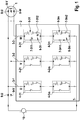
- the Figures 1 and 2 show a schematic representation of a charging system according to the invention.
- a controllable energy store 2 is connected to a three-phase electrical machine 1.
- the controllable energy store 2 comprises three energy supply branches 3-1, 3-2 and 3-3, which on the one hand have a reference potential T- (reference rail), which in the embodiment shown has a low potential, and on the other hand each have individual phases U, V, W of the electrical machine 1 are connected.
- Each of the energy supply branches 3-1, 3-2 and 3-3 has m series-connected energy storage modules 4-11 to 4-1m or 4-21 to 4-2m or 4-31 to 4-3m, where m ⁇ 2.
- the energy storage modules 4 in turn each comprise a plurality of electrical energy storage cells connected in series, which for reasons of clarity are only provided in the energy supply branch 3-3 connected to the phase W of the electrical machine 1 with reference numerals 5-31 to 5-3m.
- the energy storage modules 4 furthermore each comprise a coupling unit which is assigned to the energy storage cells 5 of the respective energy storage module 4.
- the coupling units are only provided in the energy supply branch 3-3 with reference numerals 6-31 to 6-3m.
- the coupling units 6 are each formed by two controllable switching elements 7-311 and 7-312 to 7-3m1 and 7-3m2.
- the switching elements can be designed as power semiconductor switches, for example in the form of IGBTs (Insulated Gate Bipolar Transistors) or as MOSFETs (Metal Oxide Semiconductor Field-Effect Transistors).
- the coupling units 6 make it possible to interrupt the respective energy supply branch 3 by opening both switching elements 7 of a coupling unit 6.
- the energy storage cells 5 can either be bridged by closing one of the switching elements 7 of a coupling unit 6, for example Closing the switch 7-311 or in the respective power supply branch 3, for example closing the switch 7-312.
- the total output voltages of the power supply branches 3-1 to 3-3 are determined by the respective switching state of the controllable switching elements 7 of the coupling units 6 and can be set in stages.
- the gradation is a function of the voltage of the individual energy storage modules 4. If one proceeds from the preferred embodiment of energy storage modules 4 of the same design, the maximum possible total output voltage results from the voltage of an individual energy storage module 4 times the number m of those per power supply branch 3 energy storage modules connected in series 4.
- the coupling units 6 thus allow the phases U, V, W of the electrical machine 1 to be switched either to a high reference potential or to a low reference potential and, in so far, can also perform the function of a known inverter.
- the power and operating mode of the electrical machine 1 can thus be controlled by the controllable energy store 2 with suitable activation of the coupling units 6.
- the controllable energy store 2 thus fulfills a double function in that it serves on the one hand for the electrical energy supply and on the other hand also for the control of the electrical machine 1.
- the electrical machine 1 has stator windings 8-U, 8-V and 8-W, which are connected to one another in a known manner in a star connection.
- the electrical machine 1 is designed as a three-phase three-phase machine, but can also have fewer or more than three phases.
- the number of energy supply branches 3 in controllable energy store 2 also depends on the number of phases of the electrical machine.
- each energy storage module 4 has a plurality of energy storage cells 5 connected in series.
- the energy storage modules 4 can also each have only a single energy storage cell or energy storage cells connected in parallel.
- the coupling units 6 are each formed by two controllable switching elements 7.
- the coupling units 6 can, however, also be implemented by more or less controllable switching elements, as long as the necessary functions (interrupting the energy supply branch, bridging the energy supply cells and switching the energy supply cells in the energy supply branch) can be implemented.
- Exemplary alternative configurations of a coupling unit result from the earlier applications DE 10 2010 027 857 A1 and DE 10 2010 027 861 A1 ,
- the two phases U and V are each electrically connected via a diode 9-U or 9-V with a positive pole of a charging device 10, which is shown in the form of an equivalent circuit diagram as a DC voltage source , connected.
- the charging device 10 provides a DC voltage suitable for charging the energy storage cells 5 and can e.g. be designed as a mains charger (single or three-phase, galvanically isolated or connecting).
- the negative pole of the charging device 10 is connected to the reference rail T-.
- the charging process of the energy storage cells 5 of an individual energy storage module 4, namely the energy storage cells 5-31 of the energy storage module 4-31 in the energy supply branch 3-3, is described below by way of example.
- the coupling units 6-31 to 6-3m of the energy storage modules 4-31 to 4-3m, which are located in the energy supply branch 3-3, in which the energy storage cells 5-31 to be charged are located, by a control unit (not shown) controlled that the respectively assigned energy storage cells are bridged 5-31 to 5-3m.
- a control unit not shown
- All other coupling units 6, that is, all coupling units 6 in the energy storage modules 4 of the other two energy supply branches 3-1 and 3-2 are controlled in such a way that the respective energy supply branches 3-1 and 3-2 are interrupted. Specifically, this is achieved in that both switching elements 7 of the coupling units 6 are opened.
- Such control of the coupling units 6 causes a current to flow through the stator windings 8, so that electrical energy is stored in the stator windings 8 during the charging phase.
- the coupling unit 6-31 which is assigned to the energy storage cells 5-31 to be charged, is controlled in such a way that the assigned energy storage cells 5-31 are connected to the energy supply branch 3-3. This is specifically achieved by closing the switching element 7-312 and opening the switching element 7-311.
- All other coupling units 6-32 to 6-3m which are located in the energy supply branch 3-3 of the energy storage cells 5-31 to be charged, but which are themselves not assigned to any energy storage cells 5 to be charged, are controlled in such a way that the respectively assigned energy storage cells 5-32 bridged up to 5-3m (closing the switching elements 7-321 to 7-3m1 and opening the switching elements 7-322 to 7-3m2).
- the coupling units 6-11 to 6-1 m and 6-21 to 6-2m in the other power supply branches 3-1 and 3-2 are further controlled in such a way that the respective power supply branches 3-1 and 3-2 are interrupted.
- Such control of the coupling units 6 brings about an electrical connection of the stator windings 8 to the energy storage cells 5-31 to be charged.
- the inductance of the stator windings 8 drives the current further and in this way charges the energy storage cells 5-31.
- an additional external charging inductance can be used, which is connected between the charging device 10 and the electrical machine 1 or between the charging device 10 and the controllable energy store 2.
- undesired moments during the charging process can be avoided by mechanically blocking the electrical machine 1 during the charging process, e.g. with the help of a gear pawl.
- the rotor position of the electrical machine 1 can also be monitored, e.g. with the help of an appropriate sensor system, and be switched off in the event of a detected rotor movement.
Landscapes
- Engineering & Computer Science (AREA)
- Power Engineering (AREA)
- Transportation (AREA)
- Mechanical Engineering (AREA)
- Life Sciences & Earth Sciences (AREA)
- Sustainable Development (AREA)
- Sustainable Energy (AREA)
- Charge And Discharge Circuits For Batteries Or The Like (AREA)
- Electric Propulsion And Braking For Vehicles (AREA)
Description
Die Erfindung betrifft Systeme zum Laden eines Energiespeichers und Verfahren zum Betrieb der Ladesysteme.The invention relates to systems for charging an energy store and to methods for operating the charging systems.
Es zeichnet sich ab, dass in Zukunft sowohl bei stationären Anwendungen, wie z.B. Windkraftanlagen, wie auch in Fahrzeugen, wie Hybrid- oder Elektrofahrzeugen, vermehrt elektronische Systeme zum Einsatz kommen, die neue Energiespeichertechnologien mit elektrischer Antriebstechnik kombinieren. In herkömmlichen Anwendungen wird eine elektrische Maschine, welche z.B. als Drehfeldmaschine ausgeführt ist, über einen Umrichter in Form eines Wechselrichters gesteuert. Kennzeichnend für derartige Systeme ist ein sogenannter Gleichspannungszwischenkreis, über welchen ein Energiespeicher, in der Regel eine Batterie, an die Gleichspannungsseite des Wechselrichters angeschlossen ist. Um die für eine jeweilige Anwendung gegebenen Anforderungen an Leistung und Energie erfüllen zu können, werden mehrere Batteriezellen in Serie geschaltet. Da der von einem derartigen Energiespeicher bereitgestellte Strom durch alle Batteriezellen fließen muss und eine Batteriezelle nur einen begrenzten Strom leiten kann, werden oft zusätzlich Batteriezellen parallel geschaltet, um den maximalen Strom zu erhöhen.It is becoming apparent that in the future both in stationary applications such as Wind turbines, as well as in vehicles such as hybrid or electric vehicles, are increasingly using electronic systems that combine new energy storage technologies with electrical drive technology. In conventional applications, an electrical machine, e.g. is designed as a three-phase machine, controlled by a converter in the form of an inverter. Characteristic of such systems is a so-called DC voltage intermediate circuit, via which an energy store, usually a battery, is connected to the DC voltage side of the inverter. In order to be able to meet the performance and energy requirements for a particular application, several battery cells are connected in series. Since the current provided by such an energy store must flow through all battery cells and a battery cell can only conduct a limited current, additional battery cells are often connected in parallel in order to increase the maximum current.
Die Serienschaltung mehrerer Batteriezellen bringt neben einer hohen Gesamtspannung das Problem mit sich, dass der gesamte Energiespeicher ausfällt, wenn eine einzige Batteriezelle ausfällt, weil dann kein Batteriestrom mehr fließen kann. Ein solcher Ausfall des Energiespeichers kann zu einem Ausfall des Gesamtsystems führen. Bei einem Fahrzeug kann ein Ausfall der Antriebsbatterie zum "Liegenbleiben" des Fahrzeugs führen. Bei anderen Anwendungen, wie z.B. der Rotorblattverstellung von Windkraftanlagen, kann es bei ungünstigen Rahmenbedingungen, wie z.B. starkem Wind, sogar zu sicherheitsgefährdenden Situationen kommen. Daher ist stets eine hohe Zuverlässigkeit des Energiespeichers anzustreben, wobei mit "Zuverlässigkeit" die Fähigkeit eines Systems bezeichnet wird, für eine vorgegebene Zeit fehlerfrei zu arbeiten.In addition to a high total voltage, the series connection of several battery cells has the problem that the entire energy store fails if a single battery cell fails, because then no more battery current can flow. Such a failure of the energy storage device can lead to a failure of the overall system. In the case of a vehicle, a failure of the drive battery can lead to the vehicle "stopping". In other applications, such as the rotor blade adjustment of wind turbines, unfavorable general conditions, such as strong winds, can even lead to safety-threatening situations. Therefore, it is always high To strive for reliability of the energy storage device, with "reliability" being the ability of a system to work faultlessly for a predetermined time.
In den älteren Anmeldungen
Die Druckschrift
The publication
Die vorliegende Erfindung schafft ein System zum Laden mindestens einer Energiespeicherzelle in einem steuerbaren Energiespeicher, welcher der Steuerung und der elektrischen Energieversorgung einer n-phasigen elektrischen Maschine, mit n ≥ 2, dient. Dabei weist der steuerbare Energiespeicher n parallele Energieversorgungszweige auf, welche jeweils mindestens zwei in Reihe geschaltete Energiespeichermodule aufweisen, welche jeweils mindestens eine elektrische Energiespeicherzelle mit einer zugeordneten steuerbaren Koppeleinheit umfassen. Die Energieversorgungszweige sind einerseits mit einer Bezugsschiene und andererseits mit jeweils einer Phase der elektrischen Maschine verbunden. In Abhängigkeit von Steuersignalen unterbrechen die Koppeleinheiten entweder den jeweiligen Energieversorgungszweig oder sie überbrücken die jeweils zugeordneten Energiespeicherzellen oder sie schalten die jeweils zugeordneten Energiespeicherzellen in den jeweiligen Energieversorgungszweig. Um das Laden von zumindest einer der Energiespeicherzellen zu ermöglichen, sind mindestens zwei Phasen der elektrischen Maschine über jeweils mindestens eine Freilaufdiode mit einem Pluspol einer Ladeeinrichtung und die Bezugsschiene mit einem Minuspol der Ladeeinrichtung verbindbar. Die Ladeeinrichtung kann dann eine Gleichspannung zur Ladung mindestens einer Energiespeicherzelle zur Verfügung stellen.The present invention provides a system for charging at least one energy storage cell in a controllable energy store, which is used for the control and the electrical energy supply of an n-phase electrical machine, with n ≥ 2. The controllable energy store has n parallel energy supply branches, each of which has at least two energy storage modules connected in series, each of which comprises at least one electrical energy storage cell with an associated controllable coupling unit. The energy supply branches are connected on the one hand to a reference rail and on the other hand to one phase of the electrical machine. Depending on control signals, the coupling units either interrupt the respective energy supply branch or they bridge the respectively assigned energy storage cells or they switch the respectively assigned energy storage cells in the respective energy supply branch. To do that To enable charging of at least one of the energy storage cells, at least two phases of the electrical machine can each be connected via at least one free-wheeling diode to a positive pole of a charging device and the reference rail to a negative pole of the charging device. The charging device can then provide a DC voltage for charging at least one energy storage cell.
Die Erfindung schafft schließlich ein Verfahren zum Betrieb eines erfindungsgemäßen Ladesystems für eine n-phasige elektrische Maschine, mit n ≥ 2: Dabei werden mindestens zwei Phasen der elektrischen Maschine über jeweils mindestens eine Freilaufdiode mit dem Pluspol der Ladeeinrichtung und die Bezugsschiene mit dem Minuspol der Ladeeinrichtung verbunden. In einer Ladephase werden alle Koppeleinheiten derjenigen Energiespeichermodule, welche in einem Energieversorgungszweig von zu ladenden Energiespeicherzellen liegen, derart gesteuert, dass die jeweils zugeordneten Energiespeicherzellen überbrückt werden. Alle übrigen Koppeleinheiten werden derart gesteuert, dass die jeweiligen Energieversorgungszweige unterbrochen werden. In einer der Ladephase folgenden Freilaufphase werden dann alle Koppeleinheiten, welche zu ladenden Energiespeicherzellen zugeordnet sind, derart gesteuert, dass die zugeordneten Energiespeicherzellen in den jeweiligen Energieversorgungszweig geschaltet werden. Alle Koppeleinheiten, welche in dem Energieversorgungszweig von zu ladenden Energiespeicherzellen liegen, selbst aber keinen zu ladenden Energiespeicherzellen zugeordnet sind, werden derart gesteuert, dass die jeweils zugeordneten Energiespeicherzellen überbrückt werden, und alle übrigen Koppeleinheiten werden derart gesteuert, dass die jeweiligen Energieversorgungszweige unterbrochen werden.Finally, the invention provides a method for operating a charging system according to the invention for an n-phase electrical machine, with n 2 2: Here, at least two phases of the electrical machine are each connected via at least one free-wheeling diode with the positive pole of the charging device and the reference rail with the negative pole of the charging device connected. In a charging phase, all coupling units of those energy storage modules which are located in an energy supply branch of energy storage cells to be charged are controlled in such a way that the respectively assigned energy storage cells are bridged. All other coupling units are controlled in such a way that the respective energy supply branches are interrupted. In a free-running phase following the charging phase, all coupling units which are assigned to energy storage cells to be charged are then controlled in such a way that the assigned energy storage cells are switched into the respective energy supply branch. All coupling units which are located in the energy supply branch of energy storage cells to be charged, but are themselves not assigned to any energy storage cells to be charged, are controlled in such a way that the respectively assigned energy storage cells are bridged, and all other coupling units are controlled in such a way that the respective energy supply branches are interrupted.
Die Erfindung basiert auf der Grundidee, die Koppeleinheiten einerseits und die Statorwicklungen der elektrischen Maschine andererseits für eine Ladefunktion mitzunutzen. Dies wird dadurch realisiert, dass die Koppeleinheiten und die Statorwicklungen in einer Ladephase analog zu einem Hochsetzsteller betrieben werden, wobei den Statorwicklungen Energie zugeführt und dort gespeichert wird, welche anschließend in einer Freilaufphase an die zu ladenden Energiespeicherzellen abgegeben wird. Dabei entsteht nur minimaler zusätzlicher Hardware-Aufwand für die notwendigen Freilaufdioden, was mit geringen Kosten und geringem Platzbedarf einhergeht.The invention is based on the basic idea of using the coupling units on the one hand and the stator windings of the electrical machine on the other hand for a charging function. This is achieved in that the coupling units and the stator windings are operated in a charging phase analogously to a step-up converter, energy being supplied to the stator windings and stored there, which is then released to the energy storage cells to be charged in a free-running phase. This results in minimal additional hardware expenditure for the necessary freewheeling diodes, which is associated with low costs and space requirements.
Mit den erfindungsgemäßen Systemen und Verfahren ist sowohl die Ladung von Energiespeicherzellen eines einzelnen Energiespeichermoduls als auch die gleichzeitige Ladung von Energiespeicherzellen mehrerer Energiespeichermodule möglich. Im Fall einer mehrphasigen elektrischen Maschine können auch die Energiespeicherzellen von Energiespeichermodulen, welche in verschiedenen Energieversorgungszweigen liegen, gleichzeitig geladen werden.With the systems and methods according to the invention, both the charging of energy storage cells of an individual energy storage module and the simultaneous charging of energy storage cells of several energy storage modules is possible. In the case of a multi-phase electrical machine, the energy storage cells of energy storage modules, which are located in different energy supply branches, can also be charged simultaneously.
Aufgabe der Ladeeinrichtung ist es lediglich, eine geeignete Gleichspannung zur Verfügung zu stellen. Insofern kann die Ladeeinrichtung auf verschiedenen Wegen realisiert sein. Sie kann z.B. als Netzladegerät ausgestaltet sein. Dabei ist es für die Anwendbarkeit der Erfindung auch unerheblich, ob das Netzladegerät ein- oder dreiphasig oder ob es galvanisch getrennt oder verbindend ausgestaltet ist. Umfasst die Ladeeinrichtung einen Gleichspannungswandler (DC/DC-Wandler) kann dieser aufgrund der zusätzlichen Anpassstufe, welche über die als Hochsetzsteller betriebenen Koppeleinheiten und Statorwicklungen geschaffen wird, auf eine feste Ausgangsspannung ausgelegt werden, was sich vorteilhaft auf dessen Wirkungsgrad, Bauraum und Kosten auswirkt.It is only the task of the charging device to provide a suitable DC voltage. In this respect, the charging device can be implemented in various ways. It can e.g. be designed as a mains charger. It is also irrelevant for the applicability of the invention whether the mains charger is single-phase or three-phase or whether it is galvanically isolated or connected. If the charging device includes a direct voltage converter (DC / DC converter), this can be designed for a fixed output voltage due to the additional adaptation stage, which is created via the coupling units and stator windings operated as step-up converters, which has an advantageous effect on its efficiency, installation space and costs.
Um die Erzeugung unerwünschter Momente in der elektrischen Maschine während des Ladebetriebs zu vermeiden, ist eine gleichmäßige Belastung der Phasen der elektrischen Maschine anzustreben. Daher ist es gemäß einer Ausführungsform der Erfindung vorgesehen, dass der Pluspol der Ladeeinrichtung über jeweils mindestens eine Freilaufdiode mit allen Phasen der elektrischen Maschine verbindbar ist. Auf diese Weise kann sehr schnell zwischen den bestromten Phasen der elektrischen Maschine gewechselt werden, wodurch eine gleichmäßige Belastung erreicht werden kann.In order to avoid the generation of undesirable moments in the electrical machine during charging operation, an even load on the phases of the electrical machine should be aimed for. It is therefore provided according to one embodiment of the invention that the positive pole of the charging device can be connected to all phases of the electrical machine via at least one free-wheeling diode. In this way it is possible to switch very quickly between the energized phases of the electrical machine, as a result of which an even load can be achieved.
Alternativ oder zusätzlich können unerwünschte Momente während des Ladevorgangs dadurch vermieden werden, dass die elektrische Maschine während des Ladevorgangs mechanisch blockiert wird, z.B. mit Hilfe einer Getriebesperrklinke. Alternativ kann auch die Rotorlage der elektrischen Maschine überwacht werden, z.B. mit Hilfe einer entsprechenden Sensorik, und im Falle einer detektierten Rotorbewegung abgeschaltet werden.Alternatively or additionally, undesirable moments during the charging process can be avoided by mechanically blocking the electrical machine during the charging process, e.g. with the help of a gear pawl. Alternatively, the rotor position of the electrical machine can also be monitored, e.g. with the help of an appropriate sensor system, and be switched off in the event of a detected rotor movement.
Sind die Induktivitäten der Statorwicklungen der elektrischen Maschine nicht ausreichend, so kann zwischen die Ladeeinrichtung und die elektrische Maschine oder zwischen die Ladeeinrichtung und den steuerbaren Energiespeicher eine zusätzliche Ladeinduktivität geschaltet sein.If the inductances of the stator windings of the electrical machine are not sufficient, an additional charging inductance can be connected between the charging device and the electrical machine or between the charging device and the controllable energy store.
Weitere Merkmale und Vorteile von Ausführungsformen der Erfindung ergeben sich aus der nachfolgenden Beschreibung mit Bezug auf die beigefügten Zeichnungen.Further features and advantages of embodiments of the invention will become apparent from the following description with reference to the accompanying drawings.
Es zeigen:
- Fig. 1
- eine schematische Darstellung eines erfindungsgemäßen Ladesystems in einer Ladephase und
- Fig. 2
- das Ladesystem gemäß
Fig. 1 in einer Freilaufphase.
- Fig. 1
- a schematic representation of a charging system according to the invention in a charging phase and
- Fig. 2
- the charging system according to
Fig. 1 in a free running phase.
Die
Die Koppeleinheiten 6 ermöglichen es, den jeweiligen Energieversorgungszweig 3, durch Öffnen beider Schaltelemente 7 einer Koppeleinheit 6 zu unterbrechen. Alternativ können die Energiespeicherzellen 5 durch Schließen jeweils eines der Schaltelemente 7 einer Koppeleinheit 6 entweder überbrückt werden, z.B. Schließen des Schalters 7-311 oder in den jeweiligen Energieversorgungszweig 3 geschaltet werden, z.B. Schließen des Schalters 7-312.The coupling units 6 make it possible to interrupt the respective energy supply branch 3 by opening both switching elements 7 of a coupling unit 6. Alternatively, the energy storage cells 5 can either be bridged by closing one of the switching elements 7 of a coupling unit 6, for example Closing the switch 7-311 or in the respective power supply branch 3, for example closing the switch 7-312.
Die Gesamt-Ausgangsspannungen der Energieversorgungszweige 3-1 bis 3-3 werden bestimmt durch den jeweiligen Schaltzustand der steuerbaren Schaltelemente 7 der Koppeleinheiten 6 und können stufig eingestellt werden. Die Stufung ergibt sich dabei in Abhängigkeit von der Spannung der einzelnen Energiespeichermodule 4. Geht man von der bevorzugten Ausführungsform gleichartig ausgestalteter Energiespeichermodule 4 aus, so ergibt sich eine maximal mögliche Gesamt-Ausgangsspannung aus der Spannung eines einzelnen Energiespeichermoduls 4 mal der Anzahl m der pro Energieversorgungszweig 3 in Reihe geschalteten Energiespeichermodule 4.The total output voltages of the power supply branches 3-1 to 3-3 are determined by the respective switching state of the controllable switching elements 7 of the coupling units 6 and can be set in stages. The gradation is a function of the voltage of the individual energy storage modules 4. If one proceeds from the preferred embodiment of energy storage modules 4 of the same design, the maximum possible total output voltage results from the voltage of an individual energy storage module 4 times the number m of those per power supply branch 3 energy storage modules connected in series 4.
Die Koppeleinheiten 6 erlauben es damit, die Phasen U, V, W der elektrischen Maschine 1 entweder gegen ein hohes Bezugspotential oder ein niedriges Bezugspotential zu schalten und können insofern auch die Funktion eines bekannten Wechselrichters erfüllen. Damit können Leistung und Betriebsart der elektrischen Maschine 1 bei geeigneter Ansteuerung der Koppeleinheiten 6 durch den steuerbaren Energiespeicher 2 gesteuert werden. Der steuerbare Energiespeicher 2 erfüllt also insofern eine Doppelfunktion, da er einerseits der elektrischen Energieversorgung andererseits aber auch der Steuerung der elektrischen Maschine 1 dient.The coupling units 6 thus allow the phases U, V, W of the electrical machine 1 to be switched either to a high reference potential or to a low reference potential and, in so far, can also perform the function of a known inverter. The power and operating mode of the electrical machine 1 can thus be controlled by the controllable energy store 2 with suitable activation of the coupling units 6. The controllable energy store 2 thus fulfills a double function in that it serves on the one hand for the electrical energy supply and on the other hand also for the control of the electrical machine 1.
Die elektrische Maschine 1 weist Statorwicklungen 8-U, 8-V und 8-W auf, die in bekannter Weise in Sternschaltung miteinander verschaltet sind.The electrical machine 1 has stator windings 8-U, 8-V and 8-W, which are connected to one another in a known manner in a star connection.
Die elektrische Maschine 1 ist im dargestellten Ausführungsbeispiel als dreiphasige Drehstrommaschine ausgeführt, kann aber auch weniger oder mehr als drei Phasen aufweisen. Nach der Phasenanzahl der elektrischen Maschine richtet sich natürlich auch die Anzahl der Energieversorgungszweige 3 in dem steuerbaren Energiespeicher 2.In the exemplary embodiment shown, the electrical machine 1 is designed as a three-phase three-phase machine, but can also have fewer or more than three phases. Of course, the number of energy supply branches 3 in controllable energy store 2 also depends on the number of phases of the electrical machine.
Im dargestellten Ausführungsbeispiel weist jedes Energiespeichermodul 4 jeweils mehrere in Reihe geschaltete Energiespeicherzellen 5 auf. Die Energiespeichermodule 4 können aber alternativ auch jeweils nur eine einzige Energiespeicherzelle oder auch parallel geschaltete Energiespeicherzellen aufweisen.In the exemplary embodiment shown, each energy storage module 4 has a plurality of energy storage cells 5 connected in series. Alternatively, the energy storage modules 4 can also each have only a single energy storage cell or energy storage cells connected in parallel.
Im dargestellten Ausführungsbeispiel werden die Koppeleinheiten 6 jeweils durch zwei steuerbare Schaltelemente 7 gebildet. Die Koppeleinheiten 6 können aber auch durch mehr oder weniger steuerbare Schaltelemente realisiert sein, solange die notwendigen Funktionen (Unterbrechen des Energieversorgungszweiges, Überbrücken der Energieversorgungszellen und Schalten der Energieversorgungszellen in den Energieversorgungszweig) realisierbar sind. Beispielhafte alternative Ausgestaltungen einer Koppeleinheit ergeben sich aus den älteren Anmeldungen
Um die Ladung von Energiespeicherzellen 5 eines oder mehrerer Energiespeichermodule 4 zu ermöglichen, werden die beiden Phasen U und V über jeweils eine Diode 9-U bzw. 9-V elektrisch mit einem Pluspol einer Ladeeinrichtung 10, welche in Form eines Ersatzschaltbildes als Gleichspannungsquelle dargestellt ist, verbunden. Die Ladeeinrichtung 10 stellt eine zum Laden der Energiespeicherzellen 5 geeignete Gleichspannung zur Verfügung und kann z.B. als Netzladegerät (ein- oder dreiphasig, galvanisch getrennt oder verbindend) ausgestaltet sein. Der Minuspol der Ladeeinrichtung 10 wird mit der Bezugsschiene T- verbunden.In order to enable the charging of energy storage cells 5 of one or more energy storage modules 4, the two phases U and V are each electrically connected via a diode 9-U or 9-V with a positive pole of a charging
Im Folgenden wird exemplarisch der Ladevorgang der Energiespeicherzellen 5 eines einzelnen Energiespeichermoduls 4, nämlich der Energiespeicherzellen 5-31 des Energiespeichermoduls 4-31 in dem Energieversorgungszweig 3-3 beschrieben.The charging process of the energy storage cells 5 of an individual energy storage module 4, namely the energy storage cells 5-31 of the energy storage module 4-31 in the energy supply branch 3-3, is described below by way of example.
Während einer Ladephase, welche in
Eine derartige Ansteuerung der Koppeleinheiten 6 bewirkt einen Stromfluss durch die Statorwicklungen 8, so dass während der Ladephase elektrische Energie in den Statorwicklungen 8 gespeichert wird.Such control of the coupling units 6 causes a current to flow through the
In einer der Ladephase folgenden Freilaufphase, welche in
Eine derartige Steuerung der Koppeleinheiten 6 bewirkt eine elektrische Verbindung der Statorwicklungen 8 mit den zu ladenden Energiespeicherzellen 5-31. Die Induktivität der Statorwicklungen 8 treibt dabei den Strom weiter und lädt auf diese Weise die Energiespeicherzellen 5-31 auf.Such control of the coupling units 6 brings about an electrical connection of the
Reichen die Motorinduktivitäten nicht aus, kann eine zusätzliche externe Ladeinduktivität eingesetzt werden, welche zwischen die Ladeeinrichtung 10 und die elektrische Maschine 1 oder zwischen die Ladeeinrichtung 10 und den steuerbaren Energiespeicher 2 geschaltet wird.If the motor inductances are insufficient, an additional external charging inductance can be used, which is connected between the charging
Um die Erzeugung unerwünschter Momente in der elektrischen Maschine während des Ladebetriebs zu vermeiden, ist eine gleichmäßige Belastung der Phasen der elektrischen Maschine 1 anzustreben. Daher ist es vorteilhaft auch die dritte Phase W über eine weitere nicht dargestellte Freilaufdiode mit dem Pluspol der Ladeeinrichtung 10 zu verbinden. Auf diese Weise kann sehr schnell zwischen den bestromten Phasen der elektrischen Maschine 1 gewechselt werden, wodurch eine gleichmäßige Belastung erreicht werden kann.In order to avoid the generation of undesirable moments in the electrical machine during charging, an even load on the phases of the electrical machine 1 should be aimed for. It is therefore advantageous to connect the third phase W to the positive pole of the charging
Alternativ oder zusätzlich können unerwünschte Momente während des Ladevorgangs dadurch vermieden werden, dass die elektrische Maschine 1 während des Ladevorgangs mechanisch blockiert wird, z.B. mit Hilfe einer Getriebesperrklinke. Alternativ kann auch die Rotorlage der elektrischen Maschine 1 überwacht werden, z.B. mit Hilfe einer entsprechenden Sensorik, und im Falle einer detektierten Rotorbewegung abgeschaltet werden.Alternatively or additionally, undesired moments during the charging process can be avoided by mechanically blocking the electrical machine 1 during the charging process, e.g. with the help of a gear pawl. Alternatively, the rotor position of the electrical machine 1 can also be monitored, e.g. with the help of an appropriate sensor system, and be switched off in the event of a detected rotor movement.
Claims (4)
- System for charging at least one energy storage cell (5) in a controllable energy store (2), which serves to control and supply electrical energy to an n-phase electric machine (1), where n ≥ 2, wherein- the controllable energy store (2) has n parallel energy supply paths (3-1, 3-2, 3-3), which• each have at least two energy storage modules (4) connected in series, which each comprise at least one electrical energy storage cell (5) with an associated controllable coupling unit (6),• are firstly connected to a reference rail (T-) and• secondly connected to a respective phase (U, V, W) of the electric machine (1),- the coupling units (6) interrupt the respective energy supply path (3-1, 3-2; 3-3) or bypass the respectively associated energy storage cells (5) or connect the respectively associated energy storage cells (5) into the respective energy supply path (3-1, 3-2; 3-3) depending on control signals, and- the reference rail (T-) is able to be connected to a negative pole of the charging device (10),- characterized in that at least two phases (U, V) of the electric machine (1) are able to be connected to a positive pole of a charging device (10) via in each case at least one freewheeling diode (9-U, 9-V), which charging device provides a DC voltage for charging at least one energy storage cell (5).
- System according to Claim 1, wherein all of the phases (U, V, W) of the electric machine (1) are able to be connected to the positive pole of the charging device (10) via in each case at least one freewheeling diode (9) .
- System according to one of Claims 1 to 2, wherein an additional charging inductance is connected between the charging device (10) and the electric machine (1) or between the charging device (10) and the controllable energy store (2).
- Method for operating a charging system according to one of Claims 1 to 3, characterized in that- at least two phases (U, V) of the n-phase electric machine (1), where n ≥ 2, are connected to the positive pole of the charging device (10) via in each case at least one freewheeling diode (9-U, 9-V) and the reference rail (T-) is connected to the negative pole of the charging device (10),- in a charging phase• all of the coupling units (6-31 to 6-3m) of those energy storage modules (4-31 to 4-3m) located in an energy supply path (3-3) of energy storage cells (5-31) to be charged are controlled in such a way that the respectively associated energy storage cells (5-31 to 5-3m) are bypassed, and• all of the remaining coupling units (6) are controlled in such a way that the respective energy supply paths (3-1, 3-2) are interrupted, and- in a freewheeling phase that follows the charging phase• all of the coupling units (6-31) associated with energy storage cells (5-31) to be charged are controlled in such a way that the associated energy storage cells (5-31) are connected into the respective energy supply path (3-3),• all of the coupling units (6-32 to 6-3m) located in the energy supply path (3-3) of energy storage cells (5-31) to be charged but are themselves not associated with energy storage cells (5) to be charged are controlled in such a way that the respectively associated energy storage cells (5-32 to 5-3m) are bypassed, and• all of the remaining coupling units (6) are controlled in such a way that the respective energy supply paths (3-1, 3-2) are interrupted.
Applications Claiming Priority (2)
| Application Number | Priority Date | Filing Date | Title |
|---|---|---|---|
| DE102010041075A DE102010041075A1 (en) | 2010-09-20 | 2010-09-20 | Systems for charging an energy store and method for operating the charging systems |
| PCT/EP2011/064561 WO2012038175A2 (en) | 2010-09-20 | 2011-08-24 | Systems for charging an energy store, and method for operating the charging systems |
Publications (2)
| Publication Number | Publication Date |
|---|---|
| EP2619892A2 EP2619892A2 (en) | 2013-07-31 |
| EP2619892B1 true EP2619892B1 (en) | 2020-03-04 |
Family
ID=44509382
Family Applications (1)
| Application Number | Title | Priority Date | Filing Date |
|---|---|---|---|
| EP11748399.0A Active EP2619892B1 (en) | 2010-09-20 | 2011-08-24 | Systems for charging an energy store, and method for operating the charging systems |
Country Status (5)
| Country | Link |
|---|---|
| US (1) | US9793850B2 (en) |
| EP (1) | EP2619892B1 (en) |
| CN (1) | CN103109449B (en) |
| DE (1) | DE102010041075A1 (en) |
| WO (1) | WO2012038175A2 (en) |
Families Citing this family (7)
| Publication number | Priority date | Publication date | Assignee | Title |
|---|---|---|---|---|
| DE102011003863A1 (en) * | 2011-02-09 | 2012-08-09 | Robert Bosch Gmbh | System for charging an energy storage and method for operating the charging system |
| DE102012213129A1 (en) | 2012-07-26 | 2014-01-30 | Robert Bosch Gmbh | Drive system for an electric vehicle and method for charging a battery with an internal combustion engine |
| EP2810815A1 (en) * | 2013-06-07 | 2014-12-10 | Flextronics International Kft. | Energy storage system and method for the voltage adjustment of an energy store |
| WO2017114802A1 (en) * | 2015-12-29 | 2017-07-06 | Vito Nv | Device and method for the reconfiguration of a rechargeable energy storage device into separate battery connection strings |
| US11381092B2 (en) * | 2016-08-31 | 2022-07-05 | General Electric Company | Systems and methods for charging and discharging active power link modules in direct current power systems |
| DE102017124125B4 (en) * | 2017-10-17 | 2024-11-14 | Dr. Ing. H.C. F. Porsche Aktiengesellschaft | charging an energy storage device |
| US20220029431A1 (en) * | 2020-07-23 | 2022-01-27 | Aurora Flight Sciences Corporation, a subsidiary of The Boeing Company | Switchable Battery Management System |
Family Cites Families (11)
| Publication number | Priority date | Publication date | Assignee | Title |
|---|---|---|---|---|
| JP3741171B2 (en) * | 1996-06-17 | 2006-02-01 | 株式会社安川電機 | Multiple pulse width modulation power converter |
| DE19816918C2 (en) * | 1998-04-16 | 2002-07-18 | Siemens Ag | Electrical system |
| US6599655B2 (en) * | 2001-04-06 | 2003-07-29 | The Boeing Company | Procedure for performing battery reconditioning on a space vehicle designed with one battery |
| JP2005110337A (en) * | 2003-09-26 | 2005-04-21 | Sanyo Electric Co Ltd | Charger for a plurality of batteries |
| CN101588079B (en) | 2008-05-20 | 2016-01-20 | 联想(北京)有限公司 | A kind of method of supplying power to of electronic equipment, electric supply installation and electronic equipment |
| FR2937803A3 (en) * | 2008-10-23 | 2010-04-30 | Renault Sas | Rechargeable direct voltage source i.e. rechargeable battery, charging current manipulating device for e.g. hybrid motor vehicle, has controlled step-up chopper circuit connected to rechargeable direct voltage source and to filtering unit |
| US8395280B2 (en) * | 2010-02-16 | 2013-03-12 | Infineon Technologies Ag | Circuit arrangement including a multi-level converter |
| DE102010027857A1 (en) | 2010-04-16 | 2011-10-20 | Sb Limotive Company Ltd. | Coupling unit and battery module with integrated pulse inverter and increased reliability |
| DE102010027861A1 (en) | 2010-04-16 | 2011-10-20 | Sb Limotive Company Ltd. | Coupling unit and battery module with integrated pulse inverter and exchangeable cell modules |
| EP2564484B1 (en) * | 2010-04-27 | 2015-10-14 | ABB Technology AG | An energy storage device for a power compensator and a method for control thereof |
| DE102011089297B4 (en) * | 2011-12-20 | 2023-11-16 | Robert Bosch Gmbh | Energy storage device, system with energy storage device and method for controlling an energy storage device |
-
2010
- 2010-09-20 DE DE102010041075A patent/DE102010041075A1/en not_active Withdrawn
-
2011
- 2011-08-24 EP EP11748399.0A patent/EP2619892B1/en active Active
- 2011-08-24 CN CN201180045017.3A patent/CN103109449B/en active Active
- 2011-08-24 WO PCT/EP2011/064561 patent/WO2012038175A2/en active Application Filing
- 2011-08-24 US US13/825,279 patent/US9793850B2/en active Active
Non-Patent Citations (1)
| Title |
|---|
| None * |
Also Published As
| Publication number | Publication date |
|---|---|
| CN103109449A (en) | 2013-05-15 |
| WO2012038175A3 (en) | 2012-10-04 |
| CN103109449B (en) | 2016-08-17 |
| US9793850B2 (en) | 2017-10-17 |
| DE102010041075A1 (en) | 2012-03-22 |
| EP2619892A2 (en) | 2013-07-31 |
| US20130241447A1 (en) | 2013-09-19 |
| WO2012038175A2 (en) | 2012-03-29 |
Similar Documents
| Publication | Publication Date | Title |
|---|---|---|
| EP2619894B1 (en) | Method for setting a desired output voltage in a power supply branch of a controllable energy store | |
| EP2619875B1 (en) | System for charging an energy store, and method for operating the charging system | |
| EP2673829B1 (en) | Controllable energy storage and method for operating a controllable energy storage | |
| EP2619874B1 (en) | System for charging an energy store, and method for operating the charging system | |
| EP2673160B1 (en) | System for charging an energy store, and method for operating the charging system | |
| EP2658738B1 (en) | System for coupling at least one dc source to a controllable energy store and associated operating method | |
| EP2619892B1 (en) | Systems for charging an energy store, and method for operating the charging systems | |
| EP2673860B1 (en) | Charging an energy-storing arrangement | |
| WO2012038176A2 (en) | System for charging an energy store, and method for operating the charging system | |
| WO2012089395A2 (en) | Controllable energy store and method for operating a controllable energy store | |
| WO2012107148A1 (en) | System for charging an energy store, and method for operating the charging system | |
| EP2619873B1 (en) | System for charging an energy store, and method for operating the charging system | |
| WO2012107150A2 (en) | System comprising an electrically excited machine | |
| WO2012038210A2 (en) | Energy supply system and method for charging at least one energy storage cell acting as energy store for a dc-voltage intermediate circuit in an energy supply system | |
| EP2619876B1 (en) | Method for transferring energy between at least two power cells in a controllable energy store | |
| EP2673864B1 (en) | System for charging an energy store, and method for operating the charging system | |
| WO2012038182A2 (en) | System for charging an energy store, and method for operating the charging system | |
| WO2012089397A2 (en) | System for coupling at least one ac power source to a controllable energy store and associated operational method |
Legal Events
| Date | Code | Title | Description |
|---|---|---|---|
| PUAI | Public reference made under article 153(3) epc to a published international application that has entered the european phase |
Free format text: ORIGINAL CODE: 0009012 |
|
| 17P | Request for examination filed |
Effective date: 20130422 |
|
| AK | Designated contracting states |
Kind code of ref document: A2 Designated state(s): AL AT BE BG CH CY CZ DE DK EE ES FI FR GB GR HR HU IE IS IT LI LT LU LV MC MK MT NL NO PL PT RO RS SE SI SK SM TR |
|
| DAX | Request for extension of the european patent (deleted) | ||
| GRAP | Despatch of communication of intention to grant a patent |
Free format text: ORIGINAL CODE: EPIDOSNIGR1 |
|
| STAA | Information on the status of an ep patent application or granted ep patent |
Free format text: STATUS: GRANT OF PATENT IS INTENDED |
|
| INTG | Intention to grant announced |
Effective date: 20190807 |
|
| GRAJ | Information related to disapproval of communication of intention to grant by the applicant or resumption of examination proceedings by the epo deleted |
Free format text: ORIGINAL CODE: EPIDOSDIGR1 |
|
| STAA | Information on the status of an ep patent application or granted ep patent |
Free format text: STATUS: REQUEST FOR EXAMINATION WAS MADE |
|
| GRAP | Despatch of communication of intention to grant a patent |
Free format text: ORIGINAL CODE: EPIDOSNIGR1 |
|
| STAA | Information on the status of an ep patent application or granted ep patent |
Free format text: STATUS: GRANT OF PATENT IS INTENDED |
|
| INTC | Intention to grant announced (deleted) | ||
| INTG | Intention to grant announced |
Effective date: 20191205 |
|
| GRAS | Grant fee paid |
Free format text: ORIGINAL CODE: EPIDOSNIGR3 |
|
| GRAA | (expected) grant |
Free format text: ORIGINAL CODE: 0009210 |
|
| STAA | Information on the status of an ep patent application or granted ep patent |
Free format text: STATUS: THE PATENT HAS BEEN GRANTED |
|
| AK | Designated contracting states |
Kind code of ref document: B1 Designated state(s): AL AT BE BG CH CY CZ DE DK EE ES FI FR GB GR HR HU IE IS IT LI LT LU LV MC MK MT NL NO PL PT RO RS SE SI SK SM TR |
|
| REG | Reference to a national code |
Ref country code: GB Ref legal event code: FG4D Free format text: NOT ENGLISH |
|
| REG | Reference to a national code |
Ref country code: CH Ref legal event code: EP |
|
| REG | Reference to a national code |
Ref country code: AT Ref legal event code: REF Ref document number: 1241535 Country of ref document: AT Kind code of ref document: T Effective date: 20200315 |
|
| REG | Reference to a national code |
Ref country code: DE Ref legal event code: R096 Ref document number: 502011016524 Country of ref document: DE |
|
| REG | Reference to a national code |
Ref country code: IE Ref legal event code: FG4D Free format text: LANGUAGE OF EP DOCUMENT: GERMAN |
|
| RAP2 | Party data changed (patent owner data changed or rights of a patent transferred) |
Owner name: ROBERT BOSCH GMBH |
|
| PG25 | Lapsed in a contracting state [announced via postgrant information from national office to epo] |
Ref country code: RS Free format text: LAPSE BECAUSE OF FAILURE TO SUBMIT A TRANSLATION OF THE DESCRIPTION OR TO PAY THE FEE WITHIN THE PRESCRIBED TIME-LIMIT Effective date: 20200304 Ref country code: NO Free format text: LAPSE BECAUSE OF FAILURE TO SUBMIT A TRANSLATION OF THE DESCRIPTION OR TO PAY THE FEE WITHIN THE PRESCRIBED TIME-LIMIT Effective date: 20200604 Ref country code: FI Free format text: LAPSE BECAUSE OF FAILURE TO SUBMIT A TRANSLATION OF THE DESCRIPTION OR TO PAY THE FEE WITHIN THE PRESCRIBED TIME-LIMIT Effective date: 20200304 |
|
| REG | Reference to a national code |
Ref country code: NL Ref legal event code: MP Effective date: 20200304 |
|
| PG25 | Lapsed in a contracting state [announced via postgrant information from national office to epo] |
Ref country code: HR Free format text: LAPSE BECAUSE OF FAILURE TO SUBMIT A TRANSLATION OF THE DESCRIPTION OR TO PAY THE FEE WITHIN THE PRESCRIBED TIME-LIMIT Effective date: 20200304 Ref country code: GR Free format text: LAPSE BECAUSE OF FAILURE TO SUBMIT A TRANSLATION OF THE DESCRIPTION OR TO PAY THE FEE WITHIN THE PRESCRIBED TIME-LIMIT Effective date: 20200605 Ref country code: SE Free format text: LAPSE BECAUSE OF FAILURE TO SUBMIT A TRANSLATION OF THE DESCRIPTION OR TO PAY THE FEE WITHIN THE PRESCRIBED TIME-LIMIT Effective date: 20200304 Ref country code: LV Free format text: LAPSE BECAUSE OF FAILURE TO SUBMIT A TRANSLATION OF THE DESCRIPTION OR TO PAY THE FEE WITHIN THE PRESCRIBED TIME-LIMIT Effective date: 20200304 Ref country code: BG Free format text: LAPSE BECAUSE OF FAILURE TO SUBMIT A TRANSLATION OF THE DESCRIPTION OR TO PAY THE FEE WITHIN THE PRESCRIBED TIME-LIMIT Effective date: 20200604 |
|
| REG | Reference to a national code |
Ref country code: LT Ref legal event code: MG4D |
|
| PG25 | Lapsed in a contracting state [announced via postgrant information from national office to epo] |
Ref country code: NL Free format text: LAPSE BECAUSE OF FAILURE TO SUBMIT A TRANSLATION OF THE DESCRIPTION OR TO PAY THE FEE WITHIN THE PRESCRIBED TIME-LIMIT Effective date: 20200304 |
|
| PG25 | Lapsed in a contracting state [announced via postgrant information from national office to epo] |
Ref country code: RO Free format text: LAPSE BECAUSE OF FAILURE TO SUBMIT A TRANSLATION OF THE DESCRIPTION OR TO PAY THE FEE WITHIN THE PRESCRIBED TIME-LIMIT Effective date: 20200304 Ref country code: SK Free format text: LAPSE BECAUSE OF FAILURE TO SUBMIT A TRANSLATION OF THE DESCRIPTION OR TO PAY THE FEE WITHIN THE PRESCRIBED TIME-LIMIT Effective date: 20200304 Ref country code: IS Free format text: LAPSE BECAUSE OF FAILURE TO SUBMIT A TRANSLATION OF THE DESCRIPTION OR TO PAY THE FEE WITHIN THE PRESCRIBED TIME-LIMIT Effective date: 20200704 Ref country code: LT Free format text: LAPSE BECAUSE OF FAILURE TO SUBMIT A TRANSLATION OF THE DESCRIPTION OR TO PAY THE FEE WITHIN THE PRESCRIBED TIME-LIMIT Effective date: 20200304 Ref country code: CZ Free format text: LAPSE BECAUSE OF FAILURE TO SUBMIT A TRANSLATION OF THE DESCRIPTION OR TO PAY THE FEE WITHIN THE PRESCRIBED TIME-LIMIT Effective date: 20200304 Ref country code: ES Free format text: LAPSE BECAUSE OF FAILURE TO SUBMIT A TRANSLATION OF THE DESCRIPTION OR TO PAY THE FEE WITHIN THE PRESCRIBED TIME-LIMIT Effective date: 20200304 Ref country code: PT Free format text: LAPSE BECAUSE OF FAILURE TO SUBMIT A TRANSLATION OF THE DESCRIPTION OR TO PAY THE FEE WITHIN THE PRESCRIBED TIME-LIMIT Effective date: 20200729 Ref country code: EE Free format text: LAPSE BECAUSE OF FAILURE TO SUBMIT A TRANSLATION OF THE DESCRIPTION OR TO PAY THE FEE WITHIN THE PRESCRIBED TIME-LIMIT Effective date: 20200304 Ref country code: SM Free format text: LAPSE BECAUSE OF FAILURE TO SUBMIT A TRANSLATION OF THE DESCRIPTION OR TO PAY THE FEE WITHIN THE PRESCRIBED TIME-LIMIT Effective date: 20200304 |
|
| REG | Reference to a national code |
Ref country code: DE Ref legal event code: R097 Ref document number: 502011016524 Country of ref document: DE |
|
| PLBE | No opposition filed within time limit |
Free format text: ORIGINAL CODE: 0009261 |
|
| STAA | Information on the status of an ep patent application or granted ep patent |
Free format text: STATUS: NO OPPOSITION FILED WITHIN TIME LIMIT |
|
| PG25 | Lapsed in a contracting state [announced via postgrant information from national office to epo] |
Ref country code: DK Free format text: LAPSE BECAUSE OF FAILURE TO SUBMIT A TRANSLATION OF THE DESCRIPTION OR TO PAY THE FEE WITHIN THE PRESCRIBED TIME-LIMIT Effective date: 20200304 Ref country code: IT Free format text: LAPSE BECAUSE OF FAILURE TO SUBMIT A TRANSLATION OF THE DESCRIPTION OR TO PAY THE FEE WITHIN THE PRESCRIBED TIME-LIMIT Effective date: 20200304 |
|
| 26N | No opposition filed |
Effective date: 20201207 |
|
| PG25 | Lapsed in a contracting state [announced via postgrant information from national office to epo] |
Ref country code: SI Free format text: LAPSE BECAUSE OF FAILURE TO SUBMIT A TRANSLATION OF THE DESCRIPTION OR TO PAY THE FEE WITHIN THE PRESCRIBED TIME-LIMIT Effective date: 20200304 Ref country code: PL Free format text: LAPSE BECAUSE OF FAILURE TO SUBMIT A TRANSLATION OF THE DESCRIPTION OR TO PAY THE FEE WITHIN THE PRESCRIBED TIME-LIMIT Effective date: 20200304 |
|
| PG25 | Lapsed in a contracting state [announced via postgrant information from national office to epo] |
Ref country code: MC Free format text: LAPSE BECAUSE OF FAILURE TO SUBMIT A TRANSLATION OF THE DESCRIPTION OR TO PAY THE FEE WITHIN THE PRESCRIBED TIME-LIMIT Effective date: 20200304 |
|
| REG | Reference to a national code |
Ref country code: CH Ref legal event code: PL |
|
| GBPC | Gb: european patent ceased through non-payment of renewal fee |
Effective date: 20200824 |
|
| PG25 | Lapsed in a contracting state [announced via postgrant information from national office to epo] |
Ref country code: CH Free format text: LAPSE BECAUSE OF NON-PAYMENT OF DUE FEES Effective date: 20200831 Ref country code: LI Free format text: LAPSE BECAUSE OF NON-PAYMENT OF DUE FEES Effective date: 20200831 Ref country code: LU Free format text: LAPSE BECAUSE OF NON-PAYMENT OF DUE FEES Effective date: 20200824 |
|
| REG | Reference to a national code |
Ref country code: BE Ref legal event code: MM Effective date: 20200831 |
|
| PG25 | Lapsed in a contracting state [announced via postgrant information from national office to epo] |
Ref country code: BE Free format text: LAPSE BECAUSE OF NON-PAYMENT OF DUE FEES Effective date: 20200831 Ref country code: GB Free format text: LAPSE BECAUSE OF NON-PAYMENT OF DUE FEES Effective date: 20200824 Ref country code: IE Free format text: LAPSE BECAUSE OF NON-PAYMENT OF DUE FEES Effective date: 20200824 |
|
| REG | Reference to a national code |
Ref country code: AT Ref legal event code: MM01 Ref document number: 1241535 Country of ref document: AT Kind code of ref document: T Effective date: 20200824 |
|
| PG25 | Lapsed in a contracting state [announced via postgrant information from national office to epo] |
Ref country code: AT Free format text: LAPSE BECAUSE OF NON-PAYMENT OF DUE FEES Effective date: 20200824 |
|
| PG25 | Lapsed in a contracting state [announced via postgrant information from national office to epo] |
Ref country code: TR Free format text: LAPSE BECAUSE OF FAILURE TO SUBMIT A TRANSLATION OF THE DESCRIPTION OR TO PAY THE FEE WITHIN THE PRESCRIBED TIME-LIMIT Effective date: 20200304 Ref country code: MT Free format text: LAPSE BECAUSE OF FAILURE TO SUBMIT A TRANSLATION OF THE DESCRIPTION OR TO PAY THE FEE WITHIN THE PRESCRIBED TIME-LIMIT Effective date: 20200304 Ref country code: CY Free format text: LAPSE BECAUSE OF FAILURE TO SUBMIT A TRANSLATION OF THE DESCRIPTION OR TO PAY THE FEE WITHIN THE PRESCRIBED TIME-LIMIT Effective date: 20200304 |
|
| PG25 | Lapsed in a contracting state [announced via postgrant information from national office to epo] |
Ref country code: MK Free format text: LAPSE BECAUSE OF FAILURE TO SUBMIT A TRANSLATION OF THE DESCRIPTION OR TO PAY THE FEE WITHIN THE PRESCRIBED TIME-LIMIT Effective date: 20200304 Ref country code: AL Free format text: LAPSE BECAUSE OF FAILURE TO SUBMIT A TRANSLATION OF THE DESCRIPTION OR TO PAY THE FEE WITHIN THE PRESCRIBED TIME-LIMIT Effective date: 20200304 |
|
| PGFP | Annual fee paid to national office [announced via postgrant information from national office to epo] |
Ref country code: FR Payment date: 20240814 Year of fee payment: 14 |
|
| PGFP | Annual fee paid to national office [announced via postgrant information from national office to epo] |
Ref country code: DE Payment date: 20241024 Year of fee payment: 14 |