EP2619786B1 - Housing mounted image intensifier tube - Google Patents
Housing mounted image intensifier tube Download PDFInfo
- Publication number
- EP2619786B1 EP2619786B1 EP11763824.7A EP11763824A EP2619786B1 EP 2619786 B1 EP2619786 B1 EP 2619786B1 EP 11763824 A EP11763824 A EP 11763824A EP 2619786 B1 EP2619786 B1 EP 2619786B1
- Authority
- EP
- European Patent Office
- Prior art keywords
- faceplate
- image intensifier
- intensifier tube
- housing
- optical system
- Prior art date
- Legal status (The legal status is an assumption and is not a legal conclusion. Google has not performed a legal analysis and makes no representation as to the accuracy of the status listed.)
- Active
Links
Images


Classifications
-
- H—ELECTRICITY
- H01—ELECTRIC ELEMENTS
- H01J—ELECTRIC DISCHARGE TUBES OR DISCHARGE LAMPS
- H01J31/00—Cathode ray tubes; Electron beam tubes
- H01J31/08—Cathode ray tubes; Electron beam tubes having a screen on or from which an image or pattern is formed, picked up, converted, or stored
- H01J31/50—Image-conversion or image-amplification tubes, i.e. having optical, X-ray, or analogous input, and optical output
-
- G—PHYSICS
- G02—OPTICS
- G02B—OPTICAL ELEMENTS, SYSTEMS OR APPARATUS
- G02B23/00—Telescopes, e.g. binoculars; Periscopes; Instruments for viewing the inside of hollow bodies; Viewfinders; Optical aiming or sighting devices
- G02B23/12—Telescopes, e.g. binoculars; Periscopes; Instruments for viewing the inside of hollow bodies; Viewfinders; Optical aiming or sighting devices with means for image conversion or intensification
-
- Y—GENERAL TAGGING OF NEW TECHNOLOGICAL DEVELOPMENTS; GENERAL TAGGING OF CROSS-SECTIONAL TECHNOLOGIES SPANNING OVER SEVERAL SECTIONS OF THE IPC; TECHNICAL SUBJECTS COVERED BY FORMER USPC CROSS-REFERENCE ART COLLECTIONS [XRACs] AND DIGESTS
- Y10—TECHNICAL SUBJECTS COVERED BY FORMER USPC
- Y10T—TECHNICAL SUBJECTS COVERED BY FORMER US CLASSIFICATION
- Y10T29/00—Metal working
- Y10T29/49—Method of mechanical manufacture
- Y10T29/49826—Assembling or joining
Definitions
- This invention generally relates to an optical system, an image intensifier tube, and a method of mounting an image intensifier tube to an optical system.
- the objective lens 16 of monocular 10 collects available light and focuses that light on image intensifier tube assembly 12.
- the photocathode 61 is a negatively charged electrode that is coated with a photosensitive compound. When the photocathode 61 is struck by light, the absorbed energy causes electron emission due to the photoelectric effect.
- the MCP 60 of image intensifier tube assembly 12 amplifies the electron emission.
- the phosphor screen 63 of the fiber-optic of image intensifier tube assembly 12 transforms the amplified electron emission back to an enhanced light image.
- Potting material is then distributed into cylindrical recess 53 defined between power supply 57, image intensifier tube housing 20, cover 24 and image intensifier tube 13.
- the potting material is permitted to cure, thereby completing the assembly process of image intensifier tube assembly 12.
- a small amount of potting material is also distributed between the internal top surface of cover 24 and the faceplate surface 51, however, this potting has no effect on the position of image intensifier tube 13 with respect to mounting surface 22 of housing 20.
Description
- This invention generally relates to an optical system, an image intensifier tube, and a method of mounting an image intensifier tube to an optical system.
- An imaging device must be properly aligned within an optical system to meet pre-determined line of sight, image alignment and resolution requirements of the optical system. The optical system may be a camera, camcorder, night vision goggle, or night vision scope, for example. The imaging device may be an image intensifier tube or a digital imaging device, such as a CCD (charge coupled device) or a CMOS (complementary metal oxide semiconductor), for example. Misalignment between the imaging device and its objective lens, caused by a housing of the optical system, results in distortion of an image that is being viewed by the optical system and the user of said system. There is a continuing need to further develop and refine imaging devices, methods for assembling imaging devices, and methods for assembling an imaging device to a housing (or other component) of an optical system to meet line of sight, image alignment and resolution requirements of the optical system.
-
EP 2 187 425 A2 ,US 2007/103796 A1 ,GB 1 411 718 A US 2010/149633 A1 disclose an optical system comprising an image intensifier tube (with faceplate and photocathode) positioned within a housing. InUS 2007/103796 A1 ,GB 1 411 718 A US 2010/149633 A1 an objective lens mounted to an optical bench is mounted to the image intensifier tube housing. - According to the present invention there is provided an optical system according to claim 1 and claim 9 and a method of assembling an optical system according to
claim 14. - These and other aspects of the present invention will become clear from the detailed discussion below when taken into consideration with the drawings. It is to be understood that the following discussion is intended merely to illustrate the preferred embodiments of the present invention. However, the present invention is not limited to the illustrated embodiments, but is limited solely by the claims appended to this specification.
- The invention is best understood from the following detailed description when read in connection with the accompanying drawing. It is emphasized that, according to common practice, the various features of the drawings are not to scale. Included in the drawing are the following figures:
-
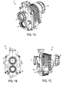
FIGS. 1A-1C depict perspective, front elevation and side elevation views, respectively, of a night vision monocular, according to an exemplary embodiment of the invention. -
FIG. 1D depicts a cross-sectional view of the monocular ofFIG. 1B taken along thelines 1D-1D, wherein several components of the monocular have been omitted. -
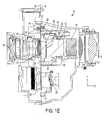
FIG. 1E depicts a cross-sectional view of the monocular ofFIG. 1B taken along the lines 1E-1E, wherein several components of the monocular have been omitted. -
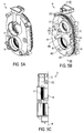
FIG. 2A depicts an exploded view of an image intensifier tube assembly of the monocular ofFIGS. 1D and1E . -
FIGS. 2B and 2C depict top-side and bottom-side perspective views, respectively, of the image intensifier tube assembly ofFIG. 2A . -
FIG. 3A depicts a cross-sectional view of the image intensifier tube assembly ofFIG. 2B taken along thelines 3A-3A. -
FIG. 3B depicts a cross-sectional view of another image intensifier tube assembly for comparison purposes with the image intensifier tube assembly shown inFIG. 3A . -
FIGS. 4A and 4B depict bottom-side and top-side perspective views, respectively, of the housing of the image intensifier tube ofFIG. 3A . -
FIG. 4C depicts a segmented top plan view of the housing ofFIG. 4A . -
FIG. 4D depicts a side view of the housing ofFIG. 4A . -
FIGS. 5A and 5B depict front-side and rear-side perspective views, respectively, of an optical bench of the monocular ofFIGS. 1A-1E . -
FIG. 5C depicts a cross-sectional view of the optical bench ofFIG. 5B taken along thelines 5C-5C. -
FIGS. 6A and 6B depict top plan and side elevation views, respectively, of a fixture for assembling the image intensifier tube assembly ofFIG. 2A . -
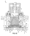
FIG. 6C depicts a cross-sectional view of the fixture ofFIG. 6A taken along thelines 6C-6C, wherein the image intensifier tube assembly ofFIG. 2A is shown positioned in the fixture. -
FIGS. 1A-1E depict a night vision monocular 10. Monocular 10 includes anobjective lens assembly 16, and an infrared focal plane array of an infrared (IR)channel 23, which are each mounted to anoptical bench 14. Aneyepiece 21 is positioned oppositeobjective lens assembly 16. As best shown inFIGS. 1D and1E , an imageintensifier tube assembly 12 is mounted tooptical bench 14 collinear withobjective lens assembly 16. Mountingsurface 22 of imageintensifier tube assembly 12, which is defined by datum plane 'A', is mounted directly to mountingsurface 37 of imageoptical bench 14, which is defined by datum plane 'B.' - Image
intensifier tube assembly 12 includes six basic components mounted within ahousing 20, i.e., aglass faceplate 50, aphotocathode 61 bonded to theglass faceplate 50, a micro-channel plate (MCP) 60, aphosphor screen 63, a fiber-optic inverter 62, and apower supply 57. Thefaceplate 50, thephotocathode 61, theMCP 60, thephosphor screen 63, and the fiber-optic inverter 62 are assembled together to form animage intensifier tube 13. - Referring now to the operation of
monocular 10, theobjective lens 16 ofmonocular 10 collects available light and focuses that light on imageintensifier tube assembly 12. Thephotocathode 61 of imageintensifier tube assembly 12, which is positioned closest toobjective lens 16, is the image plane and thus detects the light image fromobjective lens 16 and converts the light image into a corresponding electron pattern. Thephotocathode 61 is a negatively charged electrode that is coated with a photosensitive compound. When thephotocathode 61 is struck by light, the absorbed energy causes electron emission due to the photoelectric effect. TheMCP 60 of imageintensifier tube assembly 12 amplifies the electron emission. Thephosphor screen 63 of the fiber-optic of imageintensifier tube assembly 12 transforms the amplified electron emission back to an enhanced light image. Thefiber optic inverter 62 of imageintensifier tube assembly 12, which is positioned closest to abeam combiner 19, inverts the enhanced light image right side up (the image was previously inverted by objective lens 16).Beam combiner 19 combines the images generated byimage intensifier tube 13 and an infrared focal plane array of an infrared (IR)channel 23 into a single fused image. - The single enhanced image is displayed through
eyepiece 21 for viewing by a user ofmonocular 10. Alternatively, the enhanced light image may be digitally presented on a display, which may be a computer monitor or a microdisplay that is positioned before a user's eye, for example. Further details of the basic structure and operation of an image intensifier tube assembly are disclosed inU.S. Patent No. 7,482,571 . -
FIGS. 2A-2C and3A depict detailed views of imageintensifier tube assembly 12. Imageintensifier tube assembly 12 includesimage intensifier tube 13 mounted withinhousing 20, and acover 24 that is mounted to the bottom end ofhousing 20. As shown inFIGS. 1D and1E , mountingsurfaces 22A-22C of housing 20 (referred to collectively as mounting surfaces 22) are releasably mounted tooptical bench 14 by three fasteners 30 (one fastener shown inFIG. 1E ).Cover 24 is mounted to the bottom end ofhousing 20 at a location that is adjacent mountingsurfaces 22 ofhousing 20. Upon assemblingtube assembly 12 intomonocular 10, cover 24 does not physically contactoptical bench 14. - Referring now to
FIG. 3A , the design of imageintensifier tube assembly 12 introduces less tilt errors, alignment errors, and displacement errors which degrade line of sight and resolution ofmonocular 10. To achieve these benefits,faceplate surface 51 of theglass faceplate 50 is positioned on the same datum plane 'A' as the mountingsurfaces 22 of imageintensifier tube assembly 12. For reference purposes,faceplate surface 51 is the surface offaceplate 50 that is (i) disposedopposite photocathode 61; (ii) exposed through the cover 24 (seeFIG. 2C ), and (iii) positioned closest to objective lens 16 (seeFIG. 1D ). - Mounting surfaces 22 of image
intensifier tube assembly 12 are mounted directly to mountingpads 37 ofoptical bench 14, andobjective lens 16 is mounted directly tooptical bench 14. By virtue of the coplanarity offaceplate surface 51 and mountingsurface 22, coupled with the fact that both mountingsurface 22 of imageintensifier tube assembly 12 andobjective lens 16 are mounted directly tooptical bench 14, the position of imageintensifier tube assembly 12 relative toobjective lens 16 can be tightly controlled. This is significant because even slight misalignment between imageintensifier tube assembly 12 andobjective lens 16 can distort the image that is displayed to the user viaeyepiece 21 ofmonocular 10, or via a microdisplay. - By mounting the
display beam combiner 19 directly to the tube screen, theintensifier tube assembly 12 can be front-loaded. Positioningfaceplate surface 51 on the same datum plane 'A' as the mountingsurface 22 "front-loads" the imageintensifier tube assembly 12. Front-loading the imageintensifier tube assembly 12 significantly reduces the front end tilt and eliminates the need to "back-load" an image intensifier tube to meet field curvature requirements. -
FIG. 3B depicts a cross-sectional view of another imageintensifier tube assembly 150 for the purposes of comparison with the imageintensifier tube assembly 12 ofFIG. 3A . The imageintensifier tube assembly 150 ofFIG. 3B is similar to imageintensifier tube assembly 12 ofFIG. 3A , i.e., both assemblies include an image intensifier tube encased within a housing and a cover mounted to the lower end of the housing. However, in imageintensifier tube assembly 150 ofFIG. 3B ,faceplate surface 151 of imageintensifier tube assembly 150 is not coplanar with mountingsurface 153 ofcover 156. Although not shown, the mountingsurface 153 ofcover 156 is mounted to an optical bench of an optical system, and an objective lens is also mounted to that optical bench. - The distance separating
faceplate surface 151 from opticalbench mounting surface 153 varies as a result of the dimensional tolerances ofcover 156 as well as the presence ofpotting material 158 that is distributed betweencover 156 andfaceplate surface 151. Thus, the position offaceplate surface 151, and, therefore,image intensifier tube 152, can shift due to the presence ofpotting material 158 and the dimensional variations ofcover 156. Such variations cause misalignment between imageintensifier tube assembly 150 and the objective lens of the optical system (not shown), which can distort the image that is displayed to the user of the optical system. -
FIGS. 4A-4D depict detailed views ofhousing 20 of imageintensifier tube assembly 12.Housing 20 includes three mountingsurfaces surface 22 extends in a radial direction away from the longitudinal axis ofhousing 20. As best shown inFIG. 4C ,surface 22A defines a thru-hole 25 for receiving a fastener 30 (seeFIG. 1E , only one fastener shown) and a circular thru-hole 27A that is sized to just receive an alignment pin 35 (shown inFIG. 5B ). -
Surface 22B defines a thru-hole 25 for receiving a fastener 30 (seeFIG. 1E , only one fastener shown) and an ovular thru-slot 27B that is sized to just receive an alignment pin 35 (shown inFIG. 5B ) and is oriented toward the thru-hole 27A. Thru-slot 27B allows for tolerance stack reduction and differing thermal expansion rates without introducing excessive stresses. -
Surface 22C defines a thru-hole 25 for receiving afastener 30, but does not include an hole or slot that is sized to receive an alignment pin. -
FIGS. 5A-5C depict detailed views ofoptical bench 14 ofmonocular 10.Optical bench 14 includes an objective lens bore 31 for mountably receivingobjective lens assembly 16 and a lens bore 39 for mountably receiving another lens assembly for the infrared (IR) channel. Theoptical bench 14 includes three mountingpads 37A-37C (referred to collectively as pads 37), upon which imageintensifier tube assembly 12 is mounted, and four mountingpads 43A-43D upon which an IR camera is mounted. All seven mounting pads (i.e.,pads 37A-37C andpads 43A-43D) are coplanar and define datum plane 'B.' - Each image intensifier
tube mounting pad 37 includes a threadedhole 33 for receiving a fastener 30 (seeFIG. 1E , only one fastener shown). Two alignment pins 35 are fixedly positioned in holes that are defined on mountingpads monocular 10, thealignment pin 35 of mountingpad 37A is positioned through thru-hole 27A ofhousing 20 and thealignment pin 35 of mountingpad 37B is positioned through thru-slot 27B ofhousing 20 to accurately align the imageintensifier tube assembly 12 ontooptical bench 14. The alignment pins 35 also act as secondary and tertiary datums for locating objective lens bore 31 in the process of manufacturing the optical bench. -
FIGS. 6A-6C depict afixture 40 for assembling imageintensifier tube assembly 12.Fixture 40 is configured to orient theimage intensifier tube 13 along the X, Y and Z axes with respect to imageintensifier tube housing 20. As best shown inFIG. 6C ,fixture 40 includes abase plate 42 having atop surface 41 defining a datum plane 'C.'Surface 41 consists of two coplanar surfaces which define datum plane 'C', i.e.,outer surface 41A supports mountingsurfaces 22A-22C of imageintensifier tube housing 20 whereasinterior surface 41B supports the imageintensifier tube faceplate 50. - Two pins 44 (one shown) are fixedly positioned in holes that are defined on
outer surface 41A ofbase plate 42. The pins 44 extend abovetop surface 41 ofbase plate 42. The alignment pins 44 are sized to be positioned in thru-hole 27A and thru-slot 27B of imageintensifier tube housing 20. Alignment pins 44 control the position ofimage intensifier tube 13 along the X and Y axes. - An
annular recess 46 extends fromtop surface 41 ofbase plate 42 to accommodate and support thecover 24 during the potting process.Recess 46 is significant in that it permits mountingsurfaces 22 of imageintensifier tube housing 20 to reside on the same plane (i.e., datum plane 'C') asfaceplate surface 51 ofimage intensifier tube 13 while accommodatingcover 24. Conventional designs, which allow for the distribution of potting material between a cover and a faceplate, may undesirably introduce tilt and displacement to the optical alignment, as previously discussed with reference toFIG. 3B . -
Annular recess 46 is sized to receivecover 24 such thatcover 24 does not physically contacttop surface 41 ofbase plate 42. In other words, recess 46 permits imageintensifier tube cover 24 to reside at an elevation beneath datum plane 'C.' An annular-shapedfoam pad 49 is positioned withinrecess 46 to prevent damage to cover 24 during the process of assembling imageintensifier tube assembly 12.Foam pad 49 also limits the distribution of potting material betweencover 24 andfaceplate 50. - A
second recess 48 extends fromtop surface 41 ofbase plate 42 to reduce the surface area contact betweenglass faceplate 50 andtop surface 41 ofbase plate 42, thereby preventing scratches in the active area ofimage intensifier tube 13. The annular ring that formsinterior surface 41B is outside the active area ofimage intensifier tube 13. - Referring now to an exemplary method of assembling image
intensifier tube assembly 12, thefaceplate 50,photocathode 61,MCP 60 andfiber optic inverter 62 are joined together by a brazing operation to formimage intensifier tube 13 of imageintensifier tube assembly 12. The brazedimage intensifier tube 13 is then placed inside imageintensifier tube housing 20 which containspower supply 57. Imageintensifier tube cover 24 is snapped onto imageintensifier tube housing 20, thereby encapsulatingimage intensifier tube 13. - The partially-assembled image
intensifier tube assembly 12 is then loaded ontobase plate 42 offixture 40 by positioning pins 44 (seeFIG. 6C ) offixture base plate 42 through thru-hole 27A and thru-slot 27B of imageintensifier tube housing 20. The mountingsurface 22 of imageintensifier tube housing 20 andfaceplate surface 51 offaceplate 50 are both positioned onsurfaces base plate 42. In other words, mountingsurface 22 of imageintensifier tube housing 20 andfaceplate surface 51 offaceplate 50 are both positioned on datum plane 'C' ofbase plate 42. - The
piston 55 offixture 40 is driven downwardly toward imageintensifier tube assembly 12. Theannular segment 56 ofpiston 55 offixture 40 is translated into the annular space that separateswall 64 ofhousing 20 and the cylindrical exterior surface offiber optic inverter 62. Whilepiston 55 is driven downwardly, theannular segment 56 ofpiston 55 offixture 40 alignsimage intensifier tube 13 along the X and Y axes (seeFIG. 6C for axes) with respect to alignment pins 44 and thru-hole/slot 27 ofhousing 20. The relative positions ofannular segment 56 ofpiston 55 and alignment pins 44 is closely controlled. An active alignment system (not shown) may be used to moveimage intensifier tube 13 relative to the thru-hole/slot 27 by using an optical closed feedback loop if tight alignment is required. - The
piston 55 also urges imageintensifier tube housing 20 andimage intensifier tube 13 in a downward Z direction against top surface 41 (i.e., datum plane 'C') such that both mountingsurface 22 of imageintensifier tube housing 20 andfaceplate surface 51 of imageintensifier tube assembly 12 are co-planar (i.e., flush) and reside on the same datum plane 'C.' - Potting material is then distributed into
cylindrical recess 53 defined betweenpower supply 57, imageintensifier tube housing 20,cover 24 andimage intensifier tube 13. The potting material is permitted to cure, thereby completing the assembly process of imageintensifier tube assembly 12. Although not shown, a small amount of potting material is also distributed between the internal top surface ofcover 24 and thefaceplate surface 51, however, this potting has no effect on the position ofimage intensifier tube 13 with respect to mountingsurface 22 ofhousing 20. - Referring back to
FIGS. 1D and1E , once imageintensifier tube assembly 12 is potted as described above, it is ready to be mounted tooptical bench 14 ofmonocular 10.Pins 35 ofoptical bench 14 are slip fit through complimentary thru-hole 27A and thru-slot 27B of housing 20 (or vice versa), such that the longitudinal axis of imageintensifier tube assembly 12 is substantially aligned with optical axis 7 (seeFIG. 1D ) ofobjective lens 16. Theoptical bench 14 and imageintensifier tube housing 20 are then translated toward each other until mountingsurface 22 of imageintensifier tube assembly 12 abuts mountingpads 37 ofoptical bench 14, such that faceplate surface 51 (corresponding to datum plane 'A' inFIGS. 1D and1E ) resides on the same plane as mountingpads 37 of optical bench 14 (corresponding to datum plane 'B' inFIGS. 1D and1E ) andfaceplate surface 51 is substantially perpendicular to optical axis 7 ofobjective lens 16. - The alignment pins 35, thru-
hole 27A and thru-slot 27B are each sized to ensure accurate alignment of imageintensifier tube assembly 12 with respect tooptical bench 14 along the X and Y axes to meet pre-determined resolution and image alignment requirements ofmonocular 10. Afastener 30 is inserted through each thru-hole 25 ofhousing 20 and threaded into its complimentary threadedhole 33 to mount image intensifier tube housing 20 (and, thus, image intensifier tube assembly 12) tooptical bench 14. Thethermal camera bracket 17 is then mounted to mounting pads 43 ofoptical bench 14 in a similar manner as imageintensifier tube assembly 12. - In summation, the location of
image intensifier tube 13 with respect toobjective lens assembly 16 can be tightly controlled along the X and Y axes because the objective lens bore 31 (in whichobjective lens 16 is mated) is located with respect to alignment pins 35, the alignment pins 35 are positioned in thru-hole 27A and thru-slot 27B ofhousing 20, and theimage intensifier tube 13 is located with respect to thru-hole 27A and thru-slot 27B of housing 20 (as described with reference toFIG. 6C ). - Although the invention is illustrated and described herein with reference to specific embodiments, the invention is not intended to be limited to the details shown. Rather, various modifications may be made in the details within the scope of the appended claims. For example, the details of the invention are not limited to a monocular, and may apply to any optical system, such as, for example, a camera, camcorder, night vision goggle, or a night vision scope.
Claims (14)
- An optical system (10) comprising:an optical bench (14) defining a mounting surface (37);an objective lens (16) mounted to the optical bench; andan image intensifier tube (12) including:(i) a housing (20) defining an interior region and a mounting surface (22),(ii) a glass faceplate (50) defining a faceplate surface (51) and a photocathode (61) bonded to the glass faceplate wherein the glass faceplate and the photocathode are positioned within the interior region of the housing, and wherein the mounting surface of the housing resides on the same plane as the faceplate surface,wherein the mounting surface of the optical bench is mounted onto the mounting surface of the image intensifier tube housing such that the mounting surface of the optical bench resides on the same plane as the faceplate surface and the faceplate surface of the faceplate is the surface of the faceplate that is positioned closest to the objective lens.
- The optical system of claim 1 further comprising potting material distributed within the interior of the image intensifier tube housing.
- The optical system of claim 1 further comprising a cover mounted to the image intensifier tube housing.
- The optical system of claim 1 further comprising an alignment pin mounted to either the optical bench or the image intensifier tube housing, and a hole disposed in the other of the optical bench and the image intensifier tube housing, wherein the hole is sized to receive the alignment pin and the pin and hole are utilized to align the image intensifier tube with respect to the objective lens.
- The optical system of claim 1 further comprising three fasteners for mounting the image intensifier tube housing to the optical bench.
- The optical system of claim 1, wherein the faceplate surface and the photocathode are positioned on opposing sides of the glass faceplate.
- The optical system of claim 1, wherein the optical axis of the objective lens is substantially perpendicular to the faceplate surface.
- The optical system of claim 1, wherein the optical axis of the objective lens and the image intensifier tube are substantially aligned.
- An optical system comprising:an image intensifier tube (12) including:a housing (20) defining an interior region and a mounting surface (22),
wherein the mounting surface of the housing is configured for mating with a mounting surface of another optical system;a glass faceplate (50) defining a faceplate surface (51) and a photocathode (61) bonded to a glass faceplate wherein the faceplate is positioned within the interior region of the housing; anda cover (24) mounted to the housing; characterised in that the mounting surface of the housing resides on the same plane as the faceplate surface of the faceplate, with the faceplate surface being the outer surface of the faceplate. - The optical system of claim 9 further comprising potting material distributed within the interior of the image intensifier tube housing.
- The optical system of claim 9, wherein the mounting surface of the housing is flush with the faceplate surface.
- The optical system of claim 9, wherein the faceplate surface and the photocathode are positioned on opposing sides of the glass faceplate.
- The optical system of claim 9, wherein the faceplate surface of the glass faceplate is exposed through the cover.
- A method of assembling an optical system (10) comprising the steps of:mounting an objective lens (16) on an optical bench (14) adjacent a mounting surface (37) of the optical bench;mounting a faceplate (50), including a photocathode (61) bonded thereto, to an image intensifier tube housing (20) such that a mounting surface (22) of the image intensifier tube housing resides on the same plane as a faceplate surface; andjoining the mounting surface of the image intensifier tube housing with the mounting surface of the optical bench such that the mounting surface of the optical bench is substantially coplanar with the faceplate surface, the faceplate surface of the faceplate is the surface of the faceplate that is positioned closest to the objective lens, and the optical axis of the objective lens is substantially perpendicular to the faceplate surface.
Applications Claiming Priority (2)
| Application Number | Priority Date | Filing Date | Title |
|---|---|---|---|
| US12/887,904 US8507839B2 (en) | 2010-09-22 | 2010-09-22 | Image intensifier tube with a mounting surface |
| PCT/US2011/052105 WO2012040087A1 (en) | 2010-09-22 | 2011-09-19 | Housing mounted image intensifier tube |
Publications (2)
| Publication Number | Publication Date |
|---|---|
| EP2619786A1 EP2619786A1 (en) | 2013-07-31 |
| EP2619786B1 true EP2619786B1 (en) | 2014-11-12 |
Family
ID=44720155
Family Applications (1)
| Application Number | Title | Priority Date | Filing Date |
|---|---|---|---|
| EP11763824.7A Active EP2619786B1 (en) | 2010-09-22 | 2011-09-19 | Housing mounted image intensifier tube |
Country Status (6)
| Country | Link |
|---|---|
| US (1) | US8507839B2 (en) |
| EP (1) | EP2619786B1 (en) |
| JP (1) | JP6073791B2 (en) |
| KR (1) | KR101784753B1 (en) |
| CN (1) | CN103119685A (en) |
| WO (1) | WO2012040087A1 (en) |
Families Citing this family (6)
| Publication number | Priority date | Publication date | Assignee | Title |
|---|---|---|---|---|
| CN104597593B (en) * | 2013-10-30 | 2019-02-12 | 深圳市海洋王照明工程有限公司 | Look in the distance night-vision devices and visit torch |
| NL2013386B1 (en) * | 2014-08-29 | 2016-09-26 | Photonis Netherlands B V | A light-weight image intensifier sensor as well as a power supply for such a light-weight image intensifier sensor and a low-light imaging device comprising such a light-weight image intensifier sensor. |
| CN105869974B (en) * | 2016-04-08 | 2017-09-15 | 北方夜视技术股份有限公司 | A kind of method integrally assembled for gleam image intensifier |
| EP3818408A4 (en) * | 2018-07-05 | 2022-10-12 | Maranon, Inc. | Systems and method for improved night vision |
| CN109103061B (en) * | 2018-08-17 | 2024-03-29 | 深圳市荣者光电科技发展有限公司 | Packaging method of low-light-level image intensifier |
| US20230133988A1 (en) * | 2021-10-29 | 2023-05-04 | L3Harris Technologies, Inc. | Apparatus and method for a vision system having a transparent display and a diffractive, planar lens |
Family Cites Families (14)
| Publication number | Priority date | Publication date | Assignee | Title |
|---|---|---|---|---|
| US3737667A (en) * | 1971-08-18 | 1973-06-05 | B Babb | Electro-optical viewing device |
| GB1411718A (en) | 1973-01-30 | 1975-10-29 | Capsey S R | Electro-optical viewing device |
| US4733945A (en) | 1986-01-15 | 1988-03-29 | The Perkin-Elmer Corporation | Precision lens mounting |
| JPH02200074A (en) * | 1989-01-30 | 1990-08-08 | Nippon Hoso Kyokai <Nhk> | Solid-state image pickup device with image intensifier |
| US6040657A (en) * | 1997-08-15 | 2000-03-21 | Itt Manufacturing Enterprises | Thin faceplate image intensifier tube having an improved vacuum housing |
| US6331753B1 (en) * | 1999-03-18 | 2001-12-18 | Litton Systems, Inc. | Image intensifier tube |
| US6307586B1 (en) * | 1999-07-20 | 2001-10-23 | Intevac, Inc. | Electron bombarded active pixel sensor camera incorporating gain control |
| US7482571B2 (en) | 2005-08-01 | 2009-01-27 | Itt Manufacturing Enterprises, Inc. | Low cost planar image intensifier tube structure |
| US7498557B2 (en) | 2005-09-08 | 2009-03-03 | Applied Materials Israel Ltd. | Cascaded image intensifier |
| US20080007826A1 (en) * | 2005-11-04 | 2008-01-10 | Itt Manufacturing Enterprises, Inc. | Modular night vision assemblies |
| US7397617B2 (en) | 2005-11-08 | 2008-07-08 | Itt Manufacturing Enterprises, Inc. | Collimated optical system |
| US7359114B2 (en) * | 2006-06-13 | 2008-04-15 | Litton Systems, Inc. | Clip-on night vision device |
| US7880128B2 (en) | 2008-10-27 | 2011-02-01 | Itt Manufacturing Enterprises, Inc. | Vented header assembly of an image intensifier device |
| US8120845B2 (en) | 2008-12-15 | 2012-02-21 | Itt Manufacturing Enterprises, Inc. | Collimated intensified vision system and method of collimating |
-
2010
- 2010-09-22 US US12/887,904 patent/US8507839B2/en active Active
-
2011
- 2011-09-19 EP EP11763824.7A patent/EP2619786B1/en active Active
- 2011-09-19 CN CN2011800456150A patent/CN103119685A/en active Pending
- 2011-09-19 JP JP2013530208A patent/JP6073791B2/en active Active
- 2011-09-19 KR KR1020137010021A patent/KR101784753B1/en active IP Right Grant
- 2011-09-19 WO PCT/US2011/052105 patent/WO2012040087A1/en active Application Filing
Also Published As
| Publication number | Publication date |
|---|---|
| US20120069433A1 (en) | 2012-03-22 |
| WO2012040087A8 (en) | 2012-04-26 |
| WO2012040087A1 (en) | 2012-03-29 |
| US8507839B2 (en) | 2013-08-13 |
| JP2013539870A (en) | 2013-10-28 |
| EP2619786A1 (en) | 2013-07-31 |
| JP6073791B2 (en) | 2017-02-01 |
| CN103119685A (en) | 2013-05-22 |
| KR20130102599A (en) | 2013-09-17 |
| KR101784753B1 (en) | 2017-10-12 |
Similar Documents
| Publication | Publication Date | Title |
|---|---|---|
| EP2434269B1 (en) | Method of aligning an imaging device in an optical system | |
| EP2619786B1 (en) | Housing mounted image intensifier tube | |
| US7880127B2 (en) | Apparatus and method for aligning an image sensor including a header alignment means | |
| US8071932B2 (en) | Apparatus and method for sealing an image intensifier device | |
| EP2574037B1 (en) | Image pickup apparatus having imaging sensor package | |
| JP5148080B2 (en) | Low cost planar image intensifier tube structure | |
| JP6722287B2 (en) | Stereoscopic imaging sensor device and method for manufacturing an image sensor pair used for stereoscopic imaging | |
| US7880128B2 (en) | Vented header assembly of an image intensifier device | |
| TWI465788B (en) | Camera module and method for assemblying the same | |
| WO2023036122A1 (en) | Optical drive assembly, optical lens and assembly method therefor, camera module, and electronic device | |
| CN115473949A (en) | Camera device, terminal equipment and assembling method of camera device | |
| JP2020129016A (en) | Optical system, imaging system, and imaging device | |
| CN113359267B (en) | Light field lens and assembling method | |
| US7294820B2 (en) | Night vision system including field replaceable image intensifier tube | |
| JP2010091823A (en) | Method for manufacturing optical unit, method for manufacturing imaging unit, optical unit, and imaging unit | |
| US5363148A (en) | CRT display set and optical device having means for accurately positioning the CRT | |
| JP2015047249A (en) | Endoscope | |
| JP2019082545A (en) | Image capturing device |
Legal Events
| Date | Code | Title | Description |
|---|---|---|---|
| PUAI | Public reference made under article 153(3) epc to a published international application that has entered the european phase |
Free format text: ORIGINAL CODE: 0009012 |
|
| 17P | Request for examination filed |
Effective date: 20130311 |
|
| AK | Designated contracting states |
Kind code of ref document: A1 Designated state(s): AL AT BE BG CH CY CZ DE DK EE ES FI FR GB GR HR HU IE IS IT LI LT LU LV MC MK MT NL NO PL PT RO RS SE SI SK SM TR |
|
| DAX | Request for extension of the european patent (deleted) | ||
| GRAP | Despatch of communication of intention to grant a patent |
Free format text: ORIGINAL CODE: EPIDOSNIGR1 |
|
| INTG | Intention to grant announced |
Effective date: 20140414 |
|
| GRAS | Grant fee paid |
Free format text: ORIGINAL CODE: EPIDOSNIGR3 |
|
| GRAA | (expected) grant |
Free format text: ORIGINAL CODE: 0009210 |
|
| AK | Designated contracting states |
Kind code of ref document: B1 Designated state(s): AL AT BE BG CH CY CZ DE DK EE ES FI FR GB GR HR HU IE IS IT LI LT LU LV MC MK MT NL NO PL PT RO RS SE SI SK SM TR |
|
| REG | Reference to a national code |
Ref country code: GB Ref legal event code: FG4D |
|
| REG | Reference to a national code |
Ref country code: CH Ref legal event code: EP |
|
| REG | Reference to a national code |
Ref country code: AT Ref legal event code: REF Ref document number: 696199 Country of ref document: AT Kind code of ref document: T Effective date: 20141115 |
|
| REG | Reference to a national code |
Ref country code: IE Ref legal event code: FG4D |
|
| REG | Reference to a national code |
Ref country code: DE Ref legal event code: R096 Ref document number: 602011011352 Country of ref document: DE Effective date: 20141224 |
|
| REG | Reference to a national code |
Ref country code: NL Ref legal event code: T3 |
|
| REG | Reference to a national code |
Ref country code: AT Ref legal event code: MK05 Ref document number: 696199 Country of ref document: AT Kind code of ref document: T Effective date: 20141112 |
|
| PG25 | Lapsed in a contracting state [announced via postgrant information from national office to epo] |
Ref country code: FI Free format text: LAPSE BECAUSE OF FAILURE TO SUBMIT A TRANSLATION OF THE DESCRIPTION OR TO PAY THE FEE WITHIN THE PRESCRIBED TIME-LIMIT Effective date: 20141112 Ref country code: IS Free format text: LAPSE BECAUSE OF FAILURE TO SUBMIT A TRANSLATION OF THE DESCRIPTION OR TO PAY THE FEE WITHIN THE PRESCRIBED TIME-LIMIT Effective date: 20150312 Ref country code: NO Free format text: LAPSE BECAUSE OF FAILURE TO SUBMIT A TRANSLATION OF THE DESCRIPTION OR TO PAY THE FEE WITHIN THE PRESCRIBED TIME-LIMIT Effective date: 20150212 Ref country code: PT Free format text: LAPSE BECAUSE OF FAILURE TO SUBMIT A TRANSLATION OF THE DESCRIPTION OR TO PAY THE FEE WITHIN THE PRESCRIBED TIME-LIMIT Effective date: 20150312 Ref country code: ES Free format text: LAPSE BECAUSE OF FAILURE TO SUBMIT A TRANSLATION OF THE DESCRIPTION OR TO PAY THE FEE WITHIN THE PRESCRIBED TIME-LIMIT Effective date: 20141112 Ref country code: LT Free format text: LAPSE BECAUSE OF FAILURE TO SUBMIT A TRANSLATION OF THE DESCRIPTION OR TO PAY THE FEE WITHIN THE PRESCRIBED TIME-LIMIT Effective date: 20141112 |
|
| PG25 | Lapsed in a contracting state [announced via postgrant information from national office to epo] |
Ref country code: RS Free format text: LAPSE BECAUSE OF FAILURE TO SUBMIT A TRANSLATION OF THE DESCRIPTION OR TO PAY THE FEE WITHIN THE PRESCRIBED TIME-LIMIT Effective date: 20141112 Ref country code: LV Free format text: LAPSE BECAUSE OF FAILURE TO SUBMIT A TRANSLATION OF THE DESCRIPTION OR TO PAY THE FEE WITHIN THE PRESCRIBED TIME-LIMIT Effective date: 20141112 Ref country code: AT Free format text: LAPSE BECAUSE OF FAILURE TO SUBMIT A TRANSLATION OF THE DESCRIPTION OR TO PAY THE FEE WITHIN THE PRESCRIBED TIME-LIMIT Effective date: 20141112 Ref country code: CY Free format text: LAPSE BECAUSE OF FAILURE TO SUBMIT A TRANSLATION OF THE DESCRIPTION OR TO PAY THE FEE WITHIN THE PRESCRIBED TIME-LIMIT Effective date: 20141112 Ref country code: PL Free format text: LAPSE BECAUSE OF FAILURE TO SUBMIT A TRANSLATION OF THE DESCRIPTION OR TO PAY THE FEE WITHIN THE PRESCRIBED TIME-LIMIT Effective date: 20141112 Ref country code: HR Free format text: LAPSE BECAUSE OF FAILURE TO SUBMIT A TRANSLATION OF THE DESCRIPTION OR TO PAY THE FEE WITHIN THE PRESCRIBED TIME-LIMIT Effective date: 20141112 Ref country code: GR Free format text: LAPSE BECAUSE OF FAILURE TO SUBMIT A TRANSLATION OF THE DESCRIPTION OR TO PAY THE FEE WITHIN THE PRESCRIBED TIME-LIMIT Effective date: 20150213 Ref country code: SE Free format text: LAPSE BECAUSE OF FAILURE TO SUBMIT A TRANSLATION OF THE DESCRIPTION OR TO PAY THE FEE WITHIN THE PRESCRIBED TIME-LIMIT Effective date: 20141112 |
|
| PG25 | Lapsed in a contracting state [announced via postgrant information from national office to epo] |
Ref country code: CZ Free format text: LAPSE BECAUSE OF FAILURE TO SUBMIT A TRANSLATION OF THE DESCRIPTION OR TO PAY THE FEE WITHIN THE PRESCRIBED TIME-LIMIT Effective date: 20141112 Ref country code: RO Free format text: LAPSE BECAUSE OF FAILURE TO SUBMIT A TRANSLATION OF THE DESCRIPTION OR TO PAY THE FEE WITHIN THE PRESCRIBED TIME-LIMIT Effective date: 20141112 Ref country code: EE Free format text: LAPSE BECAUSE OF FAILURE TO SUBMIT A TRANSLATION OF THE DESCRIPTION OR TO PAY THE FEE WITHIN THE PRESCRIBED TIME-LIMIT Effective date: 20141112 Ref country code: SK Free format text: LAPSE BECAUSE OF FAILURE TO SUBMIT A TRANSLATION OF THE DESCRIPTION OR TO PAY THE FEE WITHIN THE PRESCRIBED TIME-LIMIT Effective date: 20141112 Ref country code: DK Free format text: LAPSE BECAUSE OF FAILURE TO SUBMIT A TRANSLATION OF THE DESCRIPTION OR TO PAY THE FEE WITHIN THE PRESCRIBED TIME-LIMIT Effective date: 20141112 |
|
| REG | Reference to a national code |
Ref country code: DE Ref legal event code: R097 Ref document number: 602011011352 Country of ref document: DE |
|
| PLBE | No opposition filed within time limit |
Free format text: ORIGINAL CODE: 0009261 |
|
| STAA | Information on the status of an ep patent application or granted ep patent |
Free format text: STATUS: NO OPPOSITION FILED WITHIN TIME LIMIT |
|
| REG | Reference to a national code |
Ref country code: FR Ref legal event code: PLFP Year of fee payment: 5 |
|
| 26N | No opposition filed |
Effective date: 20150813 |
|
| PG25 | Lapsed in a contracting state [announced via postgrant information from national office to epo] |
Ref country code: IT Free format text: LAPSE BECAUSE OF FAILURE TO SUBMIT A TRANSLATION OF THE DESCRIPTION OR TO PAY THE FEE WITHIN THE PRESCRIBED TIME-LIMIT Effective date: 20141112 |
|
| PG25 | Lapsed in a contracting state [announced via postgrant information from national office to epo] |
Ref country code: SI Free format text: LAPSE BECAUSE OF FAILURE TO SUBMIT A TRANSLATION OF THE DESCRIPTION OR TO PAY THE FEE WITHIN THE PRESCRIBED TIME-LIMIT Effective date: 20141112 |
|
| PG25 | Lapsed in a contracting state [announced via postgrant information from national office to epo] |
Ref country code: MC Free format text: LAPSE BECAUSE OF FAILURE TO SUBMIT A TRANSLATION OF THE DESCRIPTION OR TO PAY THE FEE WITHIN THE PRESCRIBED TIME-LIMIT Effective date: 20141112 Ref country code: LU Free format text: LAPSE BECAUSE OF FAILURE TO SUBMIT A TRANSLATION OF THE DESCRIPTION OR TO PAY THE FEE WITHIN THE PRESCRIBED TIME-LIMIT Effective date: 20150919 |
|
| REG | Reference to a national code |
Ref country code: CH Ref legal event code: PL |
|
| GBPC | Gb: european patent ceased through non-payment of renewal fee |
Effective date: 20150919 |
|
| REG | Reference to a national code |
Ref country code: IE Ref legal event code: MM4A |
|
| PG25 | Lapsed in a contracting state [announced via postgrant information from national office to epo] |
Ref country code: GB Free format text: LAPSE BECAUSE OF NON-PAYMENT OF DUE FEES Effective date: 20150919 Ref country code: LI Free format text: LAPSE BECAUSE OF NON-PAYMENT OF DUE FEES Effective date: 20150930 Ref country code: CH Free format text: LAPSE BECAUSE OF NON-PAYMENT OF DUE FEES Effective date: 20150930 Ref country code: IE Free format text: LAPSE BECAUSE OF NON-PAYMENT OF DUE FEES Effective date: 20150919 |
|
| REG | Reference to a national code |
Ref country code: FR Ref legal event code: PLFP Year of fee payment: 6 |
|
| PG25 | Lapsed in a contracting state [announced via postgrant information from national office to epo] |
Ref country code: MT Free format text: LAPSE BECAUSE OF FAILURE TO SUBMIT A TRANSLATION OF THE DESCRIPTION OR TO PAY THE FEE WITHIN THE PRESCRIBED TIME-LIMIT Effective date: 20141112 |
|
| PG25 | Lapsed in a contracting state [announced via postgrant information from national office to epo] |
Ref country code: HU Free format text: LAPSE BECAUSE OF FAILURE TO SUBMIT A TRANSLATION OF THE DESCRIPTION OR TO PAY THE FEE WITHIN THE PRESCRIBED TIME-LIMIT; INVALID AB INITIO Effective date: 20110919 Ref country code: SM Free format text: LAPSE BECAUSE OF FAILURE TO SUBMIT A TRANSLATION OF THE DESCRIPTION OR TO PAY THE FEE WITHIN THE PRESCRIBED TIME-LIMIT Effective date: 20141112 Ref country code: BG Free format text: LAPSE BECAUSE OF FAILURE TO SUBMIT A TRANSLATION OF THE DESCRIPTION OR TO PAY THE FEE WITHIN THE PRESCRIBED TIME-LIMIT Effective date: 20141112 |
|
| REG | Reference to a national code |
Ref country code: FR Ref legal event code: PLFP Year of fee payment: 7 |
|
| PG25 | Lapsed in a contracting state [announced via postgrant information from national office to epo] |
Ref country code: BE Free format text: LAPSE BECAUSE OF FAILURE TO SUBMIT A TRANSLATION OF THE DESCRIPTION OR TO PAY THE FEE WITHIN THE PRESCRIBED TIME-LIMIT Effective date: 20141112 |
|
| PG25 | Lapsed in a contracting state [announced via postgrant information from national office to epo] |
Ref country code: MK Free format text: LAPSE BECAUSE OF FAILURE TO SUBMIT A TRANSLATION OF THE DESCRIPTION OR TO PAY THE FEE WITHIN THE PRESCRIBED TIME-LIMIT Effective date: 20141112 Ref country code: TR Free format text: LAPSE BECAUSE OF FAILURE TO SUBMIT A TRANSLATION OF THE DESCRIPTION OR TO PAY THE FEE WITHIN THE PRESCRIBED TIME-LIMIT Effective date: 20141112 |
|
| REG | Reference to a national code |
Ref country code: FR Ref legal event code: PLFP Year of fee payment: 8 |
|
| PG25 | Lapsed in a contracting state [announced via postgrant information from national office to epo] |
Ref country code: AL Free format text: LAPSE BECAUSE OF FAILURE TO SUBMIT A TRANSLATION OF THE DESCRIPTION OR TO PAY THE FEE WITHIN THE PRESCRIBED TIME-LIMIT Effective date: 20141112 |
|
| REG | Reference to a national code |
Ref country code: DE Ref legal event code: R082 Ref document number: 602011011352 Country of ref document: DE Representative=s name: K&L GATES LLP, DE Ref country code: DE Ref legal event code: R081 Ref document number: 602011011352 Country of ref document: DE Owner name: ELBIT SYSTEMS OF AMERICA, LLC (N.D. GES. D. ST, US Free format text: FORMER OWNER: EXELIS INC., MCLEAN, VA., US |
|
| PGFP | Annual fee paid to national office [announced via postgrant information from national office to epo] |
Ref country code: NL Payment date: 20220922 Year of fee payment: 12 Ref country code: DE Payment date: 20220920 Year of fee payment: 12 |
|
| PGFP | Annual fee paid to national office [announced via postgrant information from national office to epo] |
Ref country code: FR Payment date: 20220920 Year of fee payment: 12 |
|
| REG | Reference to a national code |
Ref country code: NL Ref legal event code: PD Owner name: HARRIS CORPORATION; US Free format text: DETAILS ASSIGNMENT: CHANGE OF OWNER(S), ASSIGNMENT; FORMER OWNER NAME: L3HARRIS TECHNOLOGIES, INC. Effective date: 20230111 Ref country code: NL Ref legal event code: HC Owner name: L3HARRIS TECHNOLOGIES, INC.; US Free format text: DETAILS ASSIGNMENT: CHANGE OF OWNER(S), CHANGE OF OWNER(S) NAME; FORMER OWNER NAME: HARRIS CORPORATION Effective date: 20230111 |
|
| P01 | Opt-out of the competence of the unified patent court (upc) registered |
Effective date: 20230627 |