EP2618446A1 - Charging system - Google Patents
Charging system Download PDFInfo
- Publication number
- EP2618446A1 EP2618446A1 EP11825029.9A EP11825029A EP2618446A1 EP 2618446 A1 EP2618446 A1 EP 2618446A1 EP 11825029 A EP11825029 A EP 11825029A EP 2618446 A1 EP2618446 A1 EP 2618446A1
- Authority
- EP
- European Patent Office
- Prior art keywords
- charging
- battery
- power
- battery device
- charging device
- Prior art date
- Legal status (The legal status is an assumption and is not a legal conclusion. Google has not performed a legal analysis and makes no representation as to the accuracy of the status listed.)
- Granted
Links
Images


Classifications
-
- H—ELECTRICITY
- H02—GENERATION; CONVERSION OR DISTRIBUTION OF ELECTRIC POWER
- H02J—ELECTRIC POWER NETWORKS; CIRCUIT ARRANGEMENTS OR SYSTEMS FOR SUPPLYING OR DISTRIBUTING ELECTRIC POWER; SYSTEMS FOR STORING ELECTRIC ENERGY
- H02J50/00—Circuit arrangements or systems for wireless supply or distribution of electric power
- H02J50/90—Circuit arrangements or systems for wireless supply or distribution of electric power involving detection or optimisation of position, e.g. alignment
-
- H—ELECTRICITY
- H01—ELECTRIC ELEMENTS
- H01M—PROCESSES OR MEANS, e.g. BATTERIES, FOR THE DIRECT CONVERSION OF CHEMICAL ENERGY INTO ELECTRICAL ENERGY
- H01M10/00—Secondary cells; Manufacture thereof
- H01M10/42—Methods or arrangements for servicing or maintenance of secondary cells or secondary half-cells
- H01M10/425—Structural combination with electronic components, e.g. electronic circuits integrated to the outside of the casing
-
- H—ELECTRICITY
- H01—ELECTRIC ELEMENTS
- H01M—PROCESSES OR MEANS, e.g. BATTERIES, FOR THE DIRECT CONVERSION OF CHEMICAL ENERGY INTO ELECTRICAL ENERGY
- H01M10/00—Secondary cells; Manufacture thereof
- H01M10/42—Methods or arrangements for servicing or maintenance of secondary cells or secondary half-cells
- H01M10/44—Methods for charging or discharging
-
- H—ELECTRICITY
- H01—ELECTRIC ELEMENTS
- H01M—PROCESSES OR MEANS, e.g. BATTERIES, FOR THE DIRECT CONVERSION OF CHEMICAL ENERGY INTO ELECTRICAL ENERGY
- H01M10/00—Secondary cells; Manufacture thereof
- H01M10/42—Methods or arrangements for servicing or maintenance of secondary cells or secondary half-cells
- H01M10/46—Accumulators structurally combined with charging apparatus
-
- H—ELECTRICITY
- H02—GENERATION; CONVERSION OR DISTRIBUTION OF ELECTRIC POWER
- H02J—ELECTRIC POWER NETWORKS; CIRCUIT ARRANGEMENTS OR SYSTEMS FOR SUPPLYING OR DISTRIBUTING ELECTRIC POWER; SYSTEMS FOR STORING ELECTRIC ENERGY
- H02J50/00—Circuit arrangements or systems for wireless supply or distribution of electric power
- H02J50/10—Circuit arrangements or systems for wireless supply or distribution of electric power using inductive coupling
- H02J50/12—Circuit arrangements or systems for wireless supply or distribution of electric power using inductive coupling of the resonant type
-
- H—ELECTRICITY
- H02—GENERATION; CONVERSION OR DISTRIBUTION OF ELECTRIC POWER
- H02J—ELECTRIC POWER NETWORKS; CIRCUIT ARRANGEMENTS OR SYSTEMS FOR SUPPLYING OR DISTRIBUTING ELECTRIC POWER; SYSTEMS FOR STORING ELECTRIC ENERGY
- H02J50/00—Circuit arrangements or systems for wireless supply or distribution of electric power
- H02J50/40—Circuit arrangements or systems for wireless supply or distribution of electric power using two or more transmitting or receiving devices
-
- H—ELECTRICITY
- H02—GENERATION; CONVERSION OR DISTRIBUTION OF ELECTRIC POWER
- H02J—ELECTRIC POWER NETWORKS; CIRCUIT ARRANGEMENTS OR SYSTEMS FOR SUPPLYING OR DISTRIBUTING ELECTRIC POWER; SYSTEMS FOR STORING ELECTRIC ENERGY
- H02J50/00—Circuit arrangements or systems for wireless supply or distribution of electric power
- H02J50/80—Circuit arrangements or systems for wireless supply or distribution of electric power involving the exchange of data, concerning supply or distribution of electric power, between transmitting devices and receiving devices
-
- H—ELECTRICITY
- H02—GENERATION; CONVERSION OR DISTRIBUTION OF ELECTRIC POWER
- H02J—ELECTRIC POWER NETWORKS; CIRCUIT ARRANGEMENTS OR SYSTEMS FOR SUPPLYING OR DISTRIBUTING ELECTRIC POWER; SYSTEMS FOR STORING ELECTRIC ENERGY
- H02J7/00—Circuit arrangements for charging or discharging batteries or for supplying loads from batteries
- H02J7/70—Circuit arrangements for charging or discharging batteries or for supplying loads from batteries characterised by the mechanical construction
-
- Y—GENERAL TAGGING OF NEW TECHNOLOGICAL DEVELOPMENTS; GENERAL TAGGING OF CROSS-SECTIONAL TECHNOLOGIES SPANNING OVER SEVERAL SECTIONS OF THE IPC; TECHNICAL SUBJECTS COVERED BY FORMER USPC CROSS-REFERENCE ART COLLECTIONS [XRACs] AND DIGESTS
- Y02—TECHNOLOGIES OR APPLICATIONS FOR MITIGATION OR ADAPTATION AGAINST CLIMATE CHANGE
- Y02E—REDUCTION OF GREENHOUSE GAS [GHG] EMISSIONS, RELATED TO ENERGY GENERATION, TRANSMISSION OR DISTRIBUTION
- Y02E60/00—Enabling technologies; Technologies with a potential or indirect contribution to GHG emissions mitigation
- Y02E60/10—Energy storage using batteries
Definitions
- the present invention relates to a power supply system, a charging control device, and a battery device.
- the present invention is devised in view of the above-mentioned program, an object of the present invention is to provide a novel and improved charging system, a novel and improved charging control device, and a novel and improved battery device of which users can use energy when the users desire to use the energy, which are easy to increase or decrease, and of which initial investment of infrastructures can be reduced.
- a charging system including at least one battery device that includes a secondary cell therein, a charging device that performs contactless power transmission to transmit power to the battery device, and a charging control device that controls the contactless power transmission between the charging device and the battery device.
- the battery device is a hexagonal cylinder having a bottom surface with a substantially regular hexagonal shape and having a predetermined height.
- the charging device is a hexagonal cylinder having a bottom surface with a substantially regular hexagonal shape and having a predetermined height.
- the contactless power transmission is performed between the charging device and the battery device under control of the charging control device by stacking the battery device on the charging device.
- the battery device may include a hole penetrating through a middle portion of a plane and a guide portion formed around the hole and stacked on the charging device at a matching position.
- the charging device may include a hole penetrating through a middle portion of a plane and a convex portion formed around the hole at a position corresponding to the guide portion to protrude from an upper surface.
- the guide portion may oscillate by a predetermined amount in a direction in which the hole penetrates, and protrudes from the plane of the battery device, when the battery device is stacked on the charging device.
- An upper portion of the charging control device may have a same size as the guide portion formed in the battery device and a lower portion of the charging control device may have a size insertable into the hole.
- Bottom surfaces of the battery device and the charging device may have same sizes and substantially regular hexagonal shapes.
- a handle may be formed in at least one side surface of the battery device.
- the charging system may further include a charging tray that has a bottom surface with a same shape as the battery device, and a miniature battery device that is charged by being installed in the charging tray and is a hexagonal cylinder having a bottom surface with a substantially regular hexagonal shape and having a predetermined height.
- a charging system including a battery device that includes a secondary cell therein, a charging device that performs contactless power transmission to transmit power to the battery device, and a charging control device that controls the contactless power transmission between the charging device and the battery device.
- the battery device is a hexagonal cylinder having a bottom surface with a substantially regular hexagonal shape and having a predetermined height, and includes a hole penetrating through a middle portion of a plane. The charging device performs the contactless power transmission, by being inserted into the hole, between the charging device and the battery device under control of the charging control device.
- FIG. 1 is an illustration of an example of the overall configuration of a power supply system 1 according to the embodiment of the present invention.
- the example of the overall configuration of the power supply system 1 according to the embodiment of the present invention will be described with reference to Fig. 1 .
- the power supply system 1 includes a charging control system 100 and battery devices 200, 300a, 300b, and 300c.
- the charging control system 100 charges the battery devices 200, 300a, 300b, and 300c by receiving the supply of power generated by a power plant 10, power generated when the solar cell 20 receives irradiation of sun-light, and power generated when the wind power generator 30 receives wind power and supplying the power to the battery devices 200, 300a, 300b, and 300c.
- the power supplied for the charging control system 100 is, of course, not limited to the power generated by the power plant 10, power generated when the solar cell 20 receives irradiation of sun-light, and power generated when the wind power generator 30 receives wind power.
- the charging control system 100 can receive the power generated by other natural energy.
- the charging control system 100 includes a charging control device 110 and a charging device 120, as shown in Fig. 1 .
- the charging control device 110 controls supply of the power from the charging device 120 to the battery devices 200, 300a, 300b, and 300c and also controls reception of the power from the battery devices 200, 300a, 300b, and 300c to the charging device 120.
- the charging control device 110 controls the supply of the power, so that the amount of power necessary in the battery devices 200, 300a, 300b, and 300c can be stored.
- the charging control device 110 may superimpose information on the power when the charging control device 110 supplies the power from the charging device 120 to the battery devices 200, 300a, 300b, and 300c.
- the information superimposed on the power can be output to devices connected to the battery devices 200, 300a, 300b, and 300c when the power stored in the battery devices 200, 300a, 300b, and 300c is used.
- the charging control device 110 preferably has a communication scheme by which wireless communication with the battery devices 200, 300a, 300b, and 300c is performed therein.
- the wireless communication scheme for example, communication using radio frequency identification (RFID) technology , a wireless communication scheme standardized in conformity with IEEE 802.15, and a short-range wireless communication scheme (Zigbee) standardized in conformity with IEEE 802.15.4 may be used.
- RFID radio frequency identification
- Zigbee short-range wireless communication scheme
- the charging device 120 supplies the power to the battery devices 200, 300a, 300b, and 300c or receives the power from the battery devices 200, 300a, 300b, and 300c.
- the supply of the power from the charging device 120 to the battery devices 200, 300a, 300b, and 300c and the reception of the power from the battery devices 200, 300a, 300b, and 300c to the charging device 120 are all performed according to a power transmission scheme (wireless power transmission) in which electrodes are not physically connected to each other.
- Examples of the wireless power transmission include power transmission types such as an electromagnetic induction type and a magnetic resonance type.
- the electromagnetic induction type is better than the magnetic resonance type in a power transmission efficiency, but a coil of a power feeding side and a coil of a power receiving side have to face each other.
- the magnetic resonance type is worse than the electromagnetic induction type in the power transmission efficiency, but has the advantage that a power transmission distance is longer than in the electromagnetic induction type.
- the wireless power transmission type is not particularly limited.
- the magnetic resonance type is preferably used in consideration of the fact that the plurality of battery devices 200 are stacked on the charging device 120 so that each of the battery devices 200 can be charged.
- the charging device 120 preferably has a communication scheme by which wireless communication is performed with the charging control device 110 or the battery devices 200, 300a, 300b, and 300c therein.
- the wireless communication scheme for example, communication using radio frequency identification (RFID) technology , a wireless communication scheme standardized in conformity with IEEE 802.15, and a short-range wireless communication scheme (Zigbee) standardized in conformity with IEEE 802.15.4 may be used.
- RFID radio frequency identification
- Zigbee short-range wireless communication scheme
- the battery devices 200, 300a, 300b, and 300c each include a secondary cell therein. Therefore, by supplying the power from the charging device 120 through wireless power transmission, the power can be stored in the internal secondary cell.
- the charging control system 100 or the battery devices 200, 300a, 300b, and 300c preferably have the communication scheme therein, as described above, and may communicate with the outside to inform the outside of the states of the secondary cells installed inside the battery devices 200, 300a, 300b, and 300c using the communication scheme.
- the shapes of the charging control device 110, the charging device 120, and the battery devices 200, 300a, 300b, and 300c will be described in detail below.
- the battery devices 300a, 300b, and 300c are smaller than the battery device 200 in size and have easily portable shapes.
- the battery devices 200, 300a, 300b, and 300c can be extracted for use in each home or the like after the battery devices 200, 300a, 300b, and 300c are charged by the charging control system 100. Therefore, when the capacity of each internal secondary cell is completely consumed or is reduced, the battery devices 200, 300a, 300b, and 300c can be brought to a place at which the charging control system 100 is installed to be charged by the charging control system 100.
- the charging control system 100 can be installed in a public facility of a school, a government office, a hospital or the like, to which power is normally supplied.
- the secondary cells included in the battery devices 200, 300a, 300b, and 300c can be charged by the charging control system 100 installed in the facility to which the power is normally supplied.
- the battery device 200 for example, sixteen lithium-ion secondary cells connected in series therein are connected in parallel in eight rows. Needless to say, the kinds or number of secondary cells according to the embodiment of the present invention is, of course, not limited to the above example.
- Figs. 2A to 2D are illustrations of the outer appearance of the charging device 120 according to the embodiment of the present invention.
- Fig. 2A is a top view illustrating the charging device 120 according to the embodiment of the present invention.
- Fig. 2B is a side view illustrating the charging device 120 according to the embodiment of the present invention.
- Fig. 2C is a front view illustrating the charging device 120 according to the embodiment of the present invention.
- Fig. 2D is a rear view illustrating the charging device 120 according to the embodiment of the present invention.
- the charging device 120 has a substantially regular hexagonal shape. As shown in Figs. 2A to 2D , the charging device 120 according to the embodiment of the present invention has a substantially regular hexagonal hollow hole 121 in a substantially middle portion of the plane. The charging device 120 includes a convex portion 122 protruding by a predetermined height from the plane around the hole 121.
- the battery device 200 can be stably installed in the charging device 120, when the battery device 200 is stacked on the charging device 120 and is charged.
- the charging device 120 includes an input terminal 123 that is supplied with power and an output terminal 124 that outputs the power.
- the charging device 120 receives, from the input terminal 123, power generated by the power plant 10, power generated when the solar cell 20 receives irradiation of sun-light, and power generated when the wind power generator 30 receives wind power.
- the charging device 120 supplies the received power to the battery device 200.
- the positions of the input terminal 123 and the output terminal 124 are, of course, not limited to the positions shown in the drawings.
- Figs. 3A to 3D are illustrations of another structure of the charging device 120 according to the embodiment of the present invention.
- Fig. 3A is a top view illustrating a charging device 120' according to the embodiment of the present invention.
- Fig. 3B is a side view illustrating the charging device 120' according to the embodiment of the present invention.
- Fig. 3C is a front view illustrating the charging device 120' according to the embodiment of the present invention.
- Fig. 3D is a bottom view illustrating the charging device 120' according to the embodiment of the present invention.
- the charging device 120' has a shape which can be inserted into a hole 201 of the battery device 200 to be described below. Specifically, as shown in Figs. 3A to 3D , the charging device 120' includes an input terminal 123' and an output terminal 124' that are installed in an upper portion of a main body 125 having a substantially regular hexagonal bottom surface, and includes a locking portion 126 that has a substantially regular hexagonal shape larger than the substantially regular hexagonal shape of the bottom surface of the main body 125.
- the input terminal 123' and the output terminal 124' are terminals that are provided with power and output the power, as in the input terminal 123 and the output terminal 124 described above.
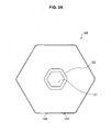
- Figs. 4A to 4C are illustrations of the structure of the battery device 200 according to the embodiment of the present invention.
- Fig. 4C is a top view illustrating the battery device 200 according to the embodiment of the present invention.
- Fig. 4B is a side view illustrating the battery device 200 according to the embodiment of the present invention.
- Fig. 4C is a front view illustrating the battery device 200 according to the embodiment of the present invention.
- the battery device 200 according to the embodiment of the present invention has a substantially regular hexagonal shape. As shown in Figs. 4A to 4C , the battery device 200 according to the embodiment of the present invention has the substantially regular hexagonal hollow hole 201 in the middle portion of the plane. The battery device 200 has a guide portion 202 around the hole 201.
- the size of the plane of the battery device 200 is the same as that of the plane of the charging device 120.
- the battery device 200 can face the charging device 120 so that the regular hexagonal shapes are maintained and overlap each other in a plan view.
- the battery device 200 preferably has a size in which sixteen lithium-ion secondary cells connected in series therein are connected in parallel in eight rows therein, as described above.
- the size of one lithium-ion battery is, for example, 26 mm in diameter and 65 mm in length.
- the battery device 200 a circuit that supplies power to the lithium-ion secondary cells, a coil that receives power from the charging device 120 or discharges the power to the charging device 120, a wireless communication unit that performs wireless communication with the charging control device 110, or the like are installed in addition to the lithium-ion secondary cells. Accordingly, the battery device 200 also preferably has a size in which the circuit, the coil, the wireless communication unit, or the like can be installed in addition to the lithium-ion secondary cells.
- the outsides of the charging device 120 and the battery device 200 are preferably formed of an integrally molded resin such as plastic. This is because the outsides of the charging device 120 and the battery device 200 are preferably formed of a material having durability, a water-proof property, and dust resistance, since the charging device 120 and the battery device 200 are assumed to be used for a long time and be carried outside.
- the contactless power transmission and reception between the charging device 120' and the battery device 200 can be also performed under the control of the charging control device 110.
- the power stored in the secondary cells included in the battery device 200 may be extracted for use through the contactless power transmission.
- a terminal (not shown) used to output power may be included in the battery device 200 and the power may be extracted for use from the terminal.
- Handles 203 are formed in side surfaces of the battery device 200. Since the handles 203 are formed in the side surfaces of the battery device 200, the battery device 200 can be easily carried. As shown in Figs. 4A to 4C , a pair of handles 203 may be formed on the side surfaces facing each other or a handle may be formed at least in one side surface.
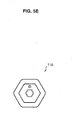
- Figs. 5A to 5E are illustrations of the structure of the charging control device 110 according to the embodiment of the present invention.
- Fig. 5A is a top view illustrating the charging control device 110.
- Fig. 5B is a front view illustrating the charging control device 110.
- Fig. 5C is a rear view illustrating the charging control device 110.
- Fig. 5D is a side view illustrating the charging control device 110.
- Fig. 5E is a bottom view illustrating the charging control device 110.
- the charging control device 110 includes a wireless communication unit, and thus communicates with the charging device 120 or the battery device 200 to control the charging between the charging device 120 and the battery device 200.
- the charging control device 110 has a plane with a substantially regular hexagonal shape.
- the charging control device 110 can be fitted into the hole 201 of the battery device 200, when contactless power feeding between the charging device 120 and the battery device 200 is performed.
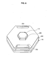
- Fig. 6 is an illustration of an installation example, when the contactless power feeding between the charging device 120 and the battery device 200 is performed, and illustrates a state in which the battery device 200 is stacked on the charging device 120 and the charging control device 110 is inserted into the hole 201 of the battery device 200.
- the contactless power feeding between the charging device 120 and the battery device 200 can be performed, so that the battery device 200 can be charged.
- the charging control device 110 into the hole 201 of the battery device 200, the contactless power feeding between the charging device 120 and the battery device 200 can be controlled in the space in which the charging device 120 can be installed.
- Fig. 7 is an illustration of an installation example when the contactless power feeding between the charging device 120' and the battery device 200 is performed, and illustrating a state in which the charging device 120' is inserted into the hole 201 of the battery device 200. In Fig. 7 , the charging control device 110 is not shown.
- the contactless power feeding between the charging device 120' and the battery device 200 can also be realized under the control of the charging control device 110, so that the battery device 200 can be charged.
- Fig. 8 is a perspective view illustrating the outer appearance of the battery device 300a according to the embodiment of the present invention.
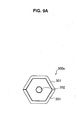
- Figs. 9A to 9D are a top view, a front view, a side view, and a bottom view illustrating the battery device 300a according to the embodiment of the present invention, respectively.
- the battery device 300a is a rectangular cylinder having a bottom surface with a substantially regular hexagonal shape. As will be described below, by arranging the battery device 300a over the charging device 120 or the battery device 200, the contactless power feeding from the charging device 120 is realized. Accordingly, the battery device 300a includes a power reception unit such as a coil by which contactless power transmission and reception with the charging device 120 or the battery device 200 can be realized.
- a power reception unit such as a coil by which contactless power transmission and reception with the charging device 120 or the battery device 200 can be realized.
- the battery device 300a has a handle 301 used to easily carry the battery device 300a.
- the battery device 300a includes a supporting member 302. A hole in which the supporting member 302 is installed can be fitted into a convex portion 401 of a charging tray 400 to be described below.
- the supporting member 302 protrudes by a predetermined height from the upper surface of the battery device 300a.
- the battery device 300a can be stacked on or arranged in the charging tray 400 to be described below.
- the power stored in the secondary cells included in the battery device 300a may be extracted for use through the contactless power transmission.
- a terminal (not shown) used to output power may be included in the battery device 300a and the power may be extracted for use from the terminal.
- the battery device 300a may be charged through the battery device 200.
- the charging tray 400 to be described below may first be placed on the battery device 200 and the battery device 300a may be installed in the charging tray 400.
- the outer appearance of the battery device 300a according to the embodiment of the present invention has been described. Next, charging and discharging control performed by the charging control system 100 according to the embodiment of the present invention will be described.
- Fig. 10 is an illustration of a functional configuration of the charging device 120 according to the embodiment of the present invention.
- the functional configuration of the charging device 120 according to the embodiment of the present invention will be described with reference to Fig. 10 .
- the charging device 120 includes a coil 131, a power reception circuit 132, a power source unit 133, and a power transmission circuit 134.
- the coil 131 performs contactless power transmission and reception to and from a coil located at a distant position. Specifically, the battery device 200 is placed on the charging device 120. Therefore, when a charging process starts under the control of the charging control device 110, the power can be transmitted and received between the coil 131 and a coil 211 of the battery device 200 to be described below.
- the coil 131 is preferably wound inside the charging device 120 so that the entire surface on which the battery device 200 is placed is covered centering on a hollow portion of the charging device 120, in order to perform the contactless power transmission and reception between the coil 131 of the charging device 120 and the coil 211 of the battery device 200.
- the power reception circuit 132 is a circuit that performs contactless power reception or detects that the coil 131 receives the power.
- the power reception circuit 132 includes a capacitor having a predetermined capacity or a resistor having a predetermined resistance value in order to perform the contactless power reception.
- the battery device 200 can be placed on the charging device 120. Therefore, when the charging process is performed under the control of the charging control device 110, the power reception circuit 132 supplies the power received by the coil 131 to the power source unit 133. Then, when the power reception circuit 132 detects that the amount of power stored in the power source unit 133 reaches a predetermined amount, the supply of the power received by the coil 131 to the power source unit 133 is stopped.
- the power source unit 133 is a unit that can store the power to be supplied to the battery device 200 via the power transmission circuit 134 and the coil 131.
- the power source unit 133 may be configured such that the power supplied from the outside of the charging device 120 is supplied to the battery device 200 via the power transmission circuit 134 and the coil 131, or a battery having a given capacity may be installed inside.
- the power transmission circuit 134 is a unit that outputs the power from the power source unit 133 to the coil 131 in order to supply the power to the battery device 200.
- the power transmission circuit 134 includes a capacitor having a predetermined capacity or a resistor having a predetermined resistance value in order to perform the contactless power transmission.
- the battery device 200 can be placed on the charging device 120. Therefore, under the control of the charging control device 110, when the charging device 120 starts the charging process of charging the battery device 200, the power transmission circuit 134 outputs the power from the power source unit 133 to the coil 131.
- the power from the power source unit 133 is output to the coil 131 by the power transmission circuit 134 and a current thus flows in the coil 131, the contactless power feeding between the charging device 120 and the battery device 200 starts.
- the functional configuration of the charging device 120 according to the embodiment of the present invention has been described with reference to Fig. 10 .
- a functional configuration of the battery device 200 according to the embodiment of the present invention will be described.
- Fig. 11 is an illustration of the functional configuration of the battery device 200 according to the embodiment of the present invention.
- the functional configuration of the battery device 200 according to the embodiment of the present invention will be described with reference to Fig. 11 .
- the battery device 200 includes a coil 211, a power reception circuit 212, a power storage unit 213, and a power transmission circuit 214.
- the coil 211 performs contactless power transmission and reception to and from a coil located at a distant position. Specifically, the battery device 200 is placed on the charging device 120. Therefore, when a charging process starts under the control of the charging control device 110, the power can be transmitted and received between the coil 211 and a coil 131 of the charging device 120.
- the power reception circuit 212 is a circuit that performs contactless power reception or detects that the coil 211 receives the power.
- the power reception circuit 212 includes a capacitor having a predetermined capacity or a resistor having a predetermined resistance value in order to perform the contactless power reception.
- the battery device 200 can be placed on the charging device 120. Therefore, when the charging process is performed under the control of the charging control device 110, the power reception circuit 212 supplies the power received by the coil 211 to the power storage unit 213. Then, when the power reception circuit 212 detects that the amount of power stored in the power storage unit 213 reaches a predetermined amount, the supply of the power received by the coil 211 to the power storage unit 213 is stopped.
- the power storage unit 213 stores the power received by the coil 211 and supplied from the power reception circuit 212.
- the power stored in the power storage unit 213 can be supplied to the outside via the power transmission circuit 214 and the coil 211. Accordingly, the power storage unit 213 may be configured by a secondary cell that has a predetermined capacity.
- the power transmission circuit 214 is a unit that outputs the power from the power storage unit 213 to the coil 211 in order to supply the power from the coil 211 to the outside (for example, the charging device 120).
- the power transmission circuit 214 includes a capacitor having a predetermined capacity or a resistor having a predetermined resistance value in order to perform the contactless power transmission.
- the battery device 200 can be placed on the charging device 120. Therefore, when the process of transmitting the power from the battery device 200 to the charging device 120 starts under the control of the charging control device 110, the power transmission circuit 214 outputs the power from the power storage unit 213 to the coil 211.
- the power from the power storage unit 213 is output to the coil 211 by the power transmission circuit 214 and a current thus flows in the coil 211, the contactless power feeding between the charging device 120 and the battery device 200 starts.
- the functional configuration of the battery device 200 according to the embodiment of the present invention has been described with reference to Fig. 11 . Next, power transmission and reception between the charging device 120 and the battery device 200 will be described according to the embodiment of the present invention.
- Figs. 12A to 12C are illustrations of the overview of the contactless power transmission and reception between the charging device 120 and the battery devices 200 according to the embodiment of the present invention.
- Figs. 12A to 12C show a case in which three battery devices 200 are stacked on the charging device 120 and the contactless power transmission and reception between the charging device 120 and the three battery devices 200 are performed under the control of the charging control device 110.
- the contactless power transmission and reception between the charging device 120 and the battery devices 200 will be described with reference to Figs. 12A to 12C according to the embodiment of the present invention.
- the charging control device 110 communicates with the charging device 120 and the battery devices 200 and performs initial setting to collect information regarding the charging device 120 and the battery devices 200.
- the initial setting may include a process of acquiring the number of battery devices 200 stacked on the charging device 120 and a process of designating a sequence in which the battery devices 200 are charged.
- An identification number may be allocated to the charging device 120.
- a storage unit such as a memory may be prepared inside the charging device 120 and the identification number of the charging device 120 may be retained in the storage unit.
- an identification number may be allocated to each of the battery devices 200 so that the battery devices 200 can be individually identified.
- a storage unit such as a memory may be prepared inside each battery device 200 and the identification number of each battery device 200 may be retained in the storage unit.
- the identification numbers retained in the charging device 120 or the battery devices 200 may be transmitted to the charging control device 110.
- the charging control device 110 can understand how much the charging device 120 outputs the power to charge the battery devices 200 or how much of the power is used by which battery device 200.
- the charging control device 110 When the charging control device 110 understands the power use status of the individual charging device 120 or battery devices 200, for example, the charging control device 110 can determine the battery device 200 to be preferentially charged or understand a power use amount necessary for an accounting process for users of the individual battery devices 200.
- the charging device 120 continuously performs the contactless power transmission to the lowermost stacked battery device 200a.
- the power transmission circuit 134 of the charging device 120 operates to transmit the power from the power source unit 133 to the lowermost stacked battery device 200a via the coil 131.
- the battery device 200a receiving the power transmitted from the charging device 120 through the contactless power transmission via the coil 211 causes the power reception circuit 212 to send the power to the power storage unit 213.
- the power storage unit 213 of the battery device 200a can store the power transmitted from the charging device 120 through the contactless power transmission therein.
- the battery device 200a transmits a charging completion notification to the charging control device 110 to inform the charging control device 110 of the completion of the charging.
- the charging control device 110 receives the charging completion notification from the battery device 200a, the charging control device 110 notifies the charging device 120 of switch of the power transmission destination from the battery device 200a to the battery device 200b.
- the power transmission circuit 134 of the charging device 120 operates to transmit the power from the power source unit 133 to the second stacked battery device 200b from the lower side via the coil 131.
- the battery device 200b receiving the power transmitted from the charging device 120 through the contactless power transmission via the coil 211 causes the power reception circuit 212 to send the power to the power storage unit 213.
- the power storage unit 213 of the battery device 200b can store the power transmitted from the charging device 120 through the contactless power transmission therein.
- the battery device 200b transmits a charging completion notification to the charging control device 110 to inform the charging control device 110 of the completion of the charging.
- the charging control device 110 receives the charging completion notification from the battery device 200b, the charging control device 110 notifies the charging device 120 of switch of the power transmission destination from the battery device 200b to the battery device 200c.
- the power transmission circuit 134 of the charging device 120 operates to transmit the power from the power source unit 133 to the uppermost stacked battery device 200c via the coil 131.
- the battery device 200c receiving the power transmitted from the charging device 120 through the contactless power transmission via the coil 211 causes the power reception circuit 212 to send the power to the power storage unit 213.
- the power storage unit 213 of the battery device 200c can store the power transmitted from the charging device 120 through the contactless power transmission therein.
- the charging device 120 can selectively switch the power transmission destination among the plurality of battery devices 200.
- the charging device 120 can use, for example, a method of changing a frequency used in the contactless power transmission.
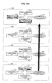
- Figs. 13A to 13C are illustrations of the overview of the contactless power transmission and reception between the charging device 120 and the battery devices 200 according to the embodiment of the present invention.
- Figs. 13A to 13C show a case in which three battery devices 200 are stacked on the charging device 120 and the contactless power transmission and reception are performed from the three battery devices 200 to the charging device 120 under the control of the charging control device 110.
- the contactless power transmission and reception between the charging device 120 and the battery devices 200 will be described with reference to Figs. 13A to 13C according to the embodiment of the present invention.
- the charging control device 110 communicates with the charging device 120 and the battery devices 200 and performs initial setting to collect information regarding the charging device 120 and the battery devices 200.
- the initial setting may include a process of acquiring the number of battery devices 200 stacked on the charging device 120 and a process of designating a sequence in which the battery devices 200 performing the power transmission are charged.
- An identification number may be allocated to the charging device 120.
- a storage unit such as a memory may be prepared inside the charging device 120 and the identification number of the charging device 120 may be retained in the storage unit.
- an identification number may be allocated to each of the battery devices 200 so that the battery devices 200 can be individually identified.
- a storage unit such as a memory may be prepared inside the battery device 200 and the identification number of each battery device 200 may be retained in the storage unit.
- the identification numbers retained in the charging device 120 or the battery devices 200 may be transmitted to the charging control device 110.
- the charging control device 110 can understand how much each battery device 200 outputs the power to charge the charging device 120 or how much of the power is used by which battery device 200.
- the charging control device 110 When the charging control device 110 understands the power use status of the individual charging device 120 or battery devices 200, for example, the charging control device 110 can determine which battery device 200 the power is preferentially transmitted from or understand a power use amount necessary for a refund process for users of the individual battery devices 200.
- the lowermost stacked battery device 200a continuously performs the contactless power transmission to the charging device 120.
- the power transmission circuit 214 of the battery device 200a operates to transmit the power from the power storage unit 213 to the charging device 120 via the coil 211.
- the charging device 120 receiving the power transmitted from the battery device 200a through the contactless power transmission via the coil 131 causes the power reception circuit 132 to send the received power to the power source unit 133.
- the power source unit 133 of the charging device 120 can store the power transmitted from the battery device 200a through the contactless power transmission therein or discharge the power to the outside of the charging device 120.
- the battery device 200a transmits a power transmission completion notification to the charging control device 110 to inform the charging control device 110 of the completion of the power transmission.
- the charging control device 110 receives the power transmission completion notification from the battery device 200a, the charging control device 110 notifies the battery device 200b of power transmission to the charging device 120.
- the power transmission circuit 214 of the battery device 200b operates to transmit the power from the power storage unit 213 to the charging device 120 via the coil 211.
- the charging device 120 receiving the power transmitted from the battery device 200b through the contactless power transmission via the coil 131 causes the power reception circuit 132 to send the received power to the power source unit 133.
- the power source unit 133 of the charging device 120 can store the power transmitted from the battery device 200b through the contactless power transmission therein or discharge the power to the outside of the charging device 120.
- the battery device 200b transmits a power transmission completion notification to the charging control device 110 to inform the charging control device 110 of the completion of the power transmission.
- the charging control device 110 receives the power transmission completion notification from the battery device 200b, the charging control device 110 notifies the battery device 200c of power transmission to the charging device 120.
- the power transmission circuit 214 of the battery device 200c operates to transmit the power from the power storage unit 213 to the charging device 120 via the coil 211.
- the charging device 120 receiving the power transmitted from the battery device 200c through the contactless power transmission via the coil 131 causes the power reception circuit 132 to send the received power to the power source unit 133.
- the power source unit 133 of the charging device 120 can store the power transmitted from the battery device 200c through the contactless power transmission therein or discharge the power to the outside of the charging device 120.
- the charging device 120 can selectively receive the power through the contactless reception from the plurality of battery devices 200.
- the charging device 120 can use, for example, a method of changing a frequency used in the contactless power transmission.
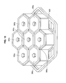
- FIG. 14 is an illustration of the outer appearance of the charging tray 400 in which the battery device 300a is installed when the battery device 300a according to the embodiment of the present invention is charged.
- Fig. 15 is an illustration of a state in which the battery devices 300a are installed in the charging tray 400 to charge the battery devices 300a.
- each battery device 300a shown in Fig. 9D is fitted into the convex portion 401, the supporting member protrudes by a predetermined height.
- the battery devices 300a can be stably installed in the charging tray.
- the charging tray 400 shown in Fig. 14 has a plane with the same substantially regular hexagonal shape as the charging device 120 and the battery device 200.
- the size of the plane of the charging tray 400 is the same as that of the charging device 120 and the battery device 200. Accordingly, when there is an area in which the charging device 120 can be installed placing the charging tray 400 on the charging device 120 or the battery device 200, the battery devices 300a installed in the charging tray 400 can be charged.
- Changing of the battery devices 300a may be performed through the battery device 200.
- the charging tray 400 to be described below may first be placed on the battery device 200 and the battery devices 300a may be installed in the charging tray 400.
- the power used to charge the battery devices 300a placed on the charging tray 400 may be supplied directly from the charging device 120 or may be supplied from the battery device 200. By supplying the power used to charge the battery devices 300a from the battery device 200, the power once stored in the battery device 200 can be subdivided to the battery devices 300a.
- the contactless power feeding from the charging device 120 to the battery devices 200, 300a, 300b, and 300c can be performed under the control of the charging control device 110.
- predetermined information may be superimposed on the power output from the charging device 120 and the contactless power feeding to the battery devices 200, 300a, 300b, and 300c may be performed.
- advertisement contents for a video may be stored along with the power in the battery device 200 and the advertisement contents may be displayed when the television is used.
- advertisement contents may be stored along with the power in the battery device 200 and the advertisement contents may be displayed when the television is used.
- audio advertisement contents may be stored along with the power in the battery device 300a and the advertisement contents may be output when the radio, the portable music player, or the like is used.
- the charging device 120 or the battery device 200 has the substantially regular hexagonal plane shape, the power supply system that is easy to increase or decrease can be realized.
- the charging device can be configured by arranging the plurality of charging devices 120 having the substantially regular hexagonal plane shapes, the plurality of charging devices 120 having the substantially regular hexagonal plane shapes may be configured to be joined together.
- the secondary cells installed inside the battery devices 200 can be charged by stacking the battery devices 200 on the charging device 120 and performing the contactless power feeding from the charging device 120 to the battery devices 200 under the control of the charging control device 110.
- the power supply system 1 By configuring the power supply system 1 in this way, as described above, users can use electric energy, when the users desire to use the electric energy. Further, since the power supply system 1 is easy to increase or decrease and it is not necessary to install power wires, the initial investment of infrastructures can be reduced.
- the plurality of battery devices 200 can be stacked on the charging device 120. Accordingly, according to the embodiment of the present invention, the contactless power feeding from the charging device 120 to the plurality of battery devices 200 can be realized, when the plurality of battery devices 200 are stacked on the charging device 120. At this time, by sequentially switching the power feeding destination of the charging device 120 under the control of the charging control device 110, the contactless power feeding to the plurality of battery devices 200 can be performed.
- the charging device 120 and the battery device 200 have the bottom surfaces of the same substantially regular hexagonal shape and each have the main body with a predetermined height, but the present invention is not limited thereto.
- the bottom surface of the charging device 120 may have a regular hexagonal shape larger than the bottom surface of the battery device 200, and vice versa.
Landscapes
- Engineering & Computer Science (AREA)
- Power Engineering (AREA)
- Computer Networks & Wireless Communication (AREA)
- Manufacturing & Machinery (AREA)
- Chemical & Material Sciences (AREA)
- Chemical Kinetics & Catalysis (AREA)
- Electrochemistry (AREA)
- General Chemical & Material Sciences (AREA)
- Microelectronics & Electronic Packaging (AREA)
- Charge And Discharge Circuits For Batteries Or The Like (AREA)
- Secondary Cells (AREA)
- Battery Mounting, Suspending (AREA)
Abstract
Description
- The present invention relates to a power supply system, a charging control device, and a battery device.
- Existing power systems are designed to transmit power generated by power plants to offices or homes via power networks constructed of electric substations, power wires, and the like. Accordingly, to realize power transmission to offices and homes, reliable power networks constructed to transmit power generated by power plants are a prerequisite. Most of the power supply systems of the related art are also designed on the assumption that reliable power networks are installed.
- In nations or areas in which such power supply systems and power distribution infrastructures are not constructed, however, there is a problem that it is difficult to apply the power supply systems without change. Further, the cost of the power distribution are not considerably lowered even in areas such as developing nations in consideration of power plants, power substations, power distribution infrastructures, and the like. Since it is difficult to maintain power distribution in a workable level from the viewpoint of the economy in such the nations or areas, there is a problem that the infrastructure may not be sufficient or, in the worst case, power failure may occur.
- It is expensive to install power wires and supply power to each home in such areas. Further, since power may not be necessary during the day, there is a high probability that appropriate returns from the installation of the power wires in each home may not be obtained.
- The present invention is devised in view of the above-mentioned program, an object of the present invention is to provide a novel and improved charging system, a novel and improved charging control device, and a novel and improved battery device of which users can use energy when the users desire to use the energy, which are easy to increase or decrease, and of which initial investment of infrastructures can be reduced.
- The present invention is provided to solve the above-mentioned issues. According to an embodiment of the present invention, there is provided a charging system including at least one battery device that includes a secondary cell therein, a charging device that performs contactless power transmission to transmit power to the battery device, and a charging control device that controls the contactless power transmission between the charging device and the battery device. The battery device is a hexagonal cylinder having a bottom surface with a substantially regular hexagonal shape and having a predetermined height. The charging device is a hexagonal cylinder having a bottom surface with a substantially regular hexagonal shape and having a predetermined height. The contactless power transmission is performed between the charging device and the battery device under control of the charging control device by stacking the battery device on the charging device.
- The battery device may include a hole penetrating through a middle portion of a plane and a guide portion formed around the hole and stacked on the charging device at a matching position. The charging device may include a hole penetrating through a middle portion of a plane and a convex portion formed around the hole at a position corresponding to the guide portion to protrude from an upper surface.
- The guide portion may oscillate by a predetermined amount in a direction in which the hole penetrates, and protrudes from the plane of the battery device, when the battery device is stacked on the charging device.
- An upper portion of the charging control device may have a same size as the guide portion formed in the battery device and a lower portion of the charging control device may have a size insertable into the hole.
- Bottom surfaces of the battery device and the charging device may have same sizes and substantially regular hexagonal shapes.
- A handle may be formed in at least one side surface of the battery device.
- The charging system may further include a charging tray that has a bottom surface with a same shape as the battery device, and a miniature battery device that is charged by being installed in the charging tray and is a hexagonal cylinder having a bottom surface with a substantially regular hexagonal shape and having a predetermined height.
- The present invention is provided to solve the above-mentioned issues. According to another embodiment of the present invention, there is provided a charging system including a battery device that includes a secondary cell therein, a charging device that performs contactless power transmission to transmit power to the battery device, and a charging control device that controls the contactless power transmission between the charging device and the battery device. The battery device is a hexagonal cylinder having a bottom surface with a substantially regular hexagonal shape and having a predetermined height, and includes a hole penetrating through a middle portion of a plane. The charging device performs the contactless power transmission, by being inserted into the hole, between the charging device and the battery device under control of the charging control device.
- According to the embodiments of the present invention described above, it is possible to provide a novel and improved charging system, a novel and improved charging control device, and a novel and improved battery of which users can use energy when the users desire to use the energy, which are easy to increase or decrease, and of which initial investment of infrastructures can be reduced.
-
- [
Fig. 1] Fig. 1 is an illustration of an example of the overall configuration of apower supply system 1 according to an embodiment of the present invention. - [
Fig. 2A] Fig. 2A is an illustration of the outer appearance of acharging device 120 according to the embodiment of the present invention. - [
Fig. 2B] Fig. 2B is an illustration of the outer appearance of thecharging device 120 according to the embodiment of the present invention. - [
Fig. 2C] Fig. 2C is an illustration of the outer appearance of thecharging device 120 according to the embodiment of the present invention. - [
Fig. 2D] Fig. 2D is an illustration of the outer appearance of thecharging device 120 according to the embodiment of the present invention. - [
Fig. 3A] Fig. 3A is an illustration of another structure of thecharging device 120. - [
Fig. 3B] Fig. 3B is an illustration of another structure of thecharging device 120. - [
Fig. 3C] Fig. 3C is an illustration of another structure of thecharging device 120. - [
Fig. 3D] Fig. 3D is an illustration of another structure of thecharging device 120. - [
Fig. 4A] Fig. 4A is an illustration of the outer appearance of abattery device 200. - [
Fig. 4B] Fig. 4B is an illustration of the outer appearance of thebattery device 200. - [
Fig. 4C] Fig. 4C is an illustration of the outer appearance of thebattery device 200. - [
Fig. 5A] Fig. 5A is an illustration of the structure of a chargingcontrol device 110. - [
Fig. 5B] Fig. 5B is an illustration of the structure of the chargingcontrol device 110. - [
Fig. 5C] Fig. 5C is an illustration of the structure of the chargingcontrol device 110. - [
Fig. 5D] Fig. 5D is an illustration of the structure of the chargingcontrol device 110. - [
Fig. 5E] Fig. 5E is an illustration of the structure of the chargingcontrol device 110. - [
Fig. 6] Fig. 6 is an illustration of an installation example when contactless power feeding between the chargingdevice 120 and thebattery device 200 is performed. - [
Fig. 7] Fig. 7 is an illustration of an installation example when contactless power feeding between a charging device 120' and thebattery device 200 is performed. - [
Fig. 8] Fig. 8 is a perspective view illustrating the outer appearance of abattery device 300a. - [
Fig. 9A] Fig. 9A is an illustration of the outer appearance of thebattery device 300a. - [
Fig. 9B] Fig. 9B is an illustration of the outer appearance of thebattery device 300a. - [
Fig. 9C] Fig. 9C is an illustration of the outer appearance of thebattery device 300a. - [
Fig. 9D] Fig. 9D is an illustration of the outer appearance of thebattery device 300a. - [
Fig. 10] Fig. 10 is an illustration of a functional configuration of thecharging device 120. - [
Fig. 11] Fig. 11 is an illustration of a functional configuration of thebattery device 200. - [
Fig. 12A] Fig. 12A is an illustration of the overview of contactless power transmitting and receiving processes for power between the chargingdevice 120 and thebattery devices 200 according to the embodiment of the present invention. - [
Fig. 12B] Fig. 12B is an illustration of the overview of the contactless power transmitting and receiving processes for power between the chargingdevice 120 and thebattery devices 200 according to the embodiment of the present invention. - [
Fig. 12C] Fig. 12C is an illustration of the overview of the contactless power transmitting and receiving processes for power between the chargingdevice 120 and thebattery devices 200 according to the embodiment of the present invention. - [
Fig. 13A] Fig. 13A is an illustration of the overview of contactless power transmitting and receiving processes for power between the chargingdevice 120 and thebattery devices 200 according to the embodiment of the present invention. - [
Fig. 13B] Fig. 13B is an illustration of the overview of the contactless power transmitting and receiving processes for power between the chargingdevice 120 and thebattery devices 200 according to the embodiment of the present invention. - [
Fig. 13C] Fig. 13C is an illustration of the overview of the contactless power transmitting and receiving processes for power between the chargingdevice 120 and thebattery devices 200 according to the embodiment of the present invention. - [
Fig. 14] Fig. 14 is an illustration of the outer appearance of a chargingtray 400. - [
Fig. 15] Fig. 15 is an illustration of a state in whichbattery devices 300a are installed in the chargingtray 400 to charge thebattery devices 300a. - Hereinafter, preferred embodiments of the present invention will be described in detail with reference to the appended drawings. Note that, in this specification and the drawings, elements that have substantially the same function and structure are denoted with the same reference signs, and repeated explanation is omitted.
- The description will be made in the following order.
- <1. Embodiment of the Present Invention>
- [1-1. Example of Overall Configuration of Power Supply System]
- [1-2. Example of Specific Structure of Each Device]
- [1-3. Charging and Discharging Control Processes]
- <2. Application Examples>
- <3. Summarization>
- First, an example of the overall configuration of a power supply system according to an embodiment of the present invention will be described.
Fig. 1 is an illustration of an example of the overall configuration of apower supply system 1 according to the embodiment of the present invention. Hereinafter, the example of the overall configuration of thepower supply system 1 according to the embodiment of the present invention will be described with reference toFig. 1 . - As shown in
Fig. 1 , thepower supply system 1 according to the embodiment of the present invention includes a chargingcontrol system 100 andbattery devices - The charging
control system 100 charges thebattery devices power plant 10, power generated when thesolar cell 20 receives irradiation of sun-light, and power generated when thewind power generator 30 receives wind power and supplying the power to thebattery devices - Needless to say, the power supplied for the charging
control system 100 is, of course, not limited to the power generated by thepower plant 10, power generated when thesolar cell 20 receives irradiation of sun-light, and power generated when thewind power generator 30 receives wind power. The chargingcontrol system 100 can receive the power generated by other natural energy. - The charging
control system 100 includes a chargingcontrol device 110 and acharging device 120, as shown inFig. 1 . - The charging
control device 110 controls supply of the power from the chargingdevice 120 to thebattery devices battery devices charging device 120. The chargingcontrol device 110 controls the supply of the power, so that the amount of power necessary in thebattery devices - The charging
control device 110 may superimpose information on the power when the chargingcontrol device 110 supplies the power from the chargingdevice 120 to thebattery devices device 120 to thebattery devices battery devices battery devices - Accordingly, the charging
control device 110 preferably has a communication scheme by which wireless communication with thebattery devices - The charging
device 120 supplies the power to thebattery devices battery devices device 120 to thebattery devices battery devices charging device 120 are all performed according to a power transmission scheme (wireless power transmission) in which electrodes are not physically connected to each other. - Examples of the wireless power transmission include power transmission types such as an electromagnetic induction type and a magnetic resonance type. The electromagnetic induction type is better than the magnetic resonance type in a power transmission efficiency, but a coil of a power feeding side and a coil of a power receiving side have to face each other. On the other hand, the magnetic resonance type is worse than the electromagnetic induction type in the power transmission efficiency, but has the advantage that a power transmission distance is longer than in the electromagnetic induction type.
- In the embodiment of the present invention, the wireless power transmission type is not particularly limited. As will be described below, however, the magnetic resonance type is preferably used in consideration of the fact that the plurality of
battery devices 200 are stacked on thecharging device 120 so that each of thebattery devices 200 can be charged. - Accordingly, the charging
device 120 preferably has a communication scheme by which wireless communication is performed with the chargingcontrol device 110 or thebattery devices - The
battery devices device 120 through wireless power transmission, the power can be stored in the internal secondary cell. - The
battery devices charging device 120 under the control of the chargingcontrol device 110. Accordingly, thebattery devices control device 110 or thecharging device 120 therein. As the wireless communication scheme, for example, communication using radio frequency identification (RFID) technology , a wireless communication scheme standardized in conformity with IEEE 802.15, and a short-range wireless communication scheme (Zigbee) standardized in conformity with IEEE 802.15.4 may be used. - The charging
control system 100 or thebattery devices battery devices - The shapes of the charging
control device 110, the chargingdevice 120, and thebattery devices battery devices battery device 200 in size and have easily portable shapes. Thebattery devices battery devices control system 100. Therefore, when the capacity of each internal secondary cell is completely consumed or is reduced, thebattery devices control system 100 is installed to be charged by the chargingcontrol system 100. - For example, the charging
control system 100 can be installed in a public facility of a school, a government office, a hospital or the like, to which power is normally supplied. The secondary cells included in thebattery devices control system 100 installed in the facility to which the power is normally supplied. - In the
battery device 200, for example, sixteen lithium-ion secondary cells connected in series therein are connected in parallel in eight rows. Needless to say, the kinds or number of secondary cells according to the embodiment of the present invention is, of course, not limited to the above example. - Thus, since the
power supply system 1 has the above-described configuration, a user can use electric energy when the user desires to use the electric energy. Further, since thepower supply system 1 is easy to increase or decrease and it is not necessary to install power wires, the initial investment of infrastructures can be reduced. - The example of the overall configuration of the
power supply system 1 according to the embodiment of the present invention has been described with reference toFig. 1 . Next, an example of a specific structure of each device of thepower supply system 1 shown inFig. 1 will be described. -
Figs. 2A to 2D are illustrations of the outer appearance of thecharging device 120 according to the embodiment of the present invention.Fig. 2A is a top view illustrating thecharging device 120 according to the embodiment of the present invention.Fig. 2B is a side view illustrating thecharging device 120 according to the embodiment of the present invention.Fig. 2C is a front view illustrating thecharging device 120 according to the embodiment of the present invention.Fig. 2D is a rear view illustrating thecharging device 120 according to the embodiment of the present invention. - As shown in
Figs. 2A to 2D , the chargingdevice 120 according to the embodiment of the present invention has a substantially regular hexagonal shape. As shown inFigs. 2A to 2D , the chargingdevice 120 according to the embodiment of the present invention has a substantially regular hexagonalhollow hole 121 in a substantially middle portion of the plane. The chargingdevice 120 includes aconvex portion 122 protruding by a predetermined height from the plane around thehole 121. - Thus, by forming the
hole 121 and theconvex portion 122 in thecharging device 120, thebattery device 200 can be stably installed in thecharging device 120, when thebattery device 200 is stacked on thecharging device 120 and is charged. - As shown in
Figs. 2A to 2D , the chargingdevice 120 according to the embodiment of the present invention includes aninput terminal 123 that is supplied with power and anoutput terminal 124 that outputs the power. The chargingdevice 120 receives, from theinput terminal 123, power generated by thepower plant 10, power generated when thesolar cell 20 receives irradiation of sun-light, and power generated when thewind power generator 30 receives wind power. The chargingdevice 120 supplies the received power to thebattery device 200. Needless to say, the positions of theinput terminal 123 and theoutput terminal 124 are, of course, not limited to the positions shown in the drawings. -
Figs. 3A to 3D are illustrations of another structure of thecharging device 120 according to the embodiment of the present invention.Fig. 3A is a top view illustrating a charging device 120' according to the embodiment of the present invention.Fig. 3B is a side view illustrating the charging device 120' according to the embodiment of the present invention.Fig. 3C is a front view illustrating the charging device 120' according to the embodiment of the present invention.Fig. 3D is a bottom view illustrating the charging device 120' according to the embodiment of the present invention. - The charging device 120' has a shape which can be inserted into a
hole 201 of thebattery device 200 to be described below. Specifically, as shown inFigs. 3A to 3D , the charging device 120' includes an input terminal 123' and an output terminal 124' that are installed in an upper portion of amain body 125 having a substantially regular hexagonal bottom surface, and includes a lockingportion 126 that has a substantially regular hexagonal shape larger than the substantially regular hexagonal shape of the bottom surface of themain body 125. The input terminal 123' and the output terminal 124' are terminals that are provided with power and output the power, as in theinput terminal 123 and theoutput terminal 124 described above. - By inserting the charging device 120' into the
hole 201 of thebattery device 200, contactless power transmission and reception between the charging device 120' and thebattery device 200 can be realized. Further, the contactless power transmission and reception mentioned here refer to movement of electric energy without physical contact realized by connectors or the like. -
Figs. 4A to 4C are illustrations of the structure of thebattery device 200 according to the embodiment of the present invention.Fig. 4C is a top view illustrating thebattery device 200 according to the embodiment of the present invention.Fig. 4B is a side view illustrating thebattery device 200 according to the embodiment of the present invention.Fig. 4C is a front view illustrating thebattery device 200 according to the embodiment of the present invention. - As shown in
Figs. 4A to 4C , thebattery device 200 according to the embodiment of the present invention has a substantially regular hexagonal shape. As shown inFigs. 4A to 4C , thebattery device 200 according to the embodiment of the present invention has the substantially regular hexagonalhollow hole 201 in the middle portion of the plane. Thebattery device 200 has aguide portion 202 around thehole 201. - The size of the plane of the
battery device 200 is the same as that of the plane of thecharging device 120. Thebattery device 200 can face thecharging device 120 so that the regular hexagonal shapes are maintained and overlap each other in a plan view. - The
battery device 200 preferably has a size in which sixteen lithium-ion secondary cells connected in series therein are connected in parallel in eight rows therein, as described above. The size of one lithium-ion battery is, for example, 26 mm in diameter and 65 mm in length. - In the
battery device 200, a circuit that supplies power to the lithium-ion secondary cells, a coil that receives power from the chargingdevice 120 or discharges the power to thecharging device 120, a wireless communication unit that performs wireless communication with the chargingcontrol device 110, or the like are installed in addition to the lithium-ion secondary cells. Accordingly, thebattery device 200 also preferably has a size in which the circuit, the coil, the wireless communication unit, or the like can be installed in addition to the lithium-ion secondary cells. - The
guide portion 202 can oscillate vertically in the direction in which the substantially regularhexagonal hole 201 is hollow. When thebattery device 200 is stacked on thecharging device 120, theguide portion 202 is configured to protrude by a predetermined height from the plane of thebattery device 200. Thus, thebattery device 200 can be stably stacked on thecharging device 120. Thebattery device 200 can be stacked on thecharging device 120, irrespective of the front and rear surfaces of thebattery device 200. - The outsides of the
charging device 120 and thebattery device 200 are preferably formed of an integrally molded resin such as plastic. This is because the outsides of thecharging device 120 and thebattery device 200 are preferably formed of a material having durability, a water-proof property, and dust resistance, since thecharging device 120 and thebattery device 200 are assumed to be used for a long time and be carried outside. - By inserting the charging device 120' into the
hole 201 of thebattery device 200, as described above, the contactless power transmission and reception between the charging device 120' and thebattery device 200 can be also performed under the control of the chargingcontrol device 110. - Various methods of using the power stored in the secondary cells included in the
battery device 200 can be considered. For example, the power stored in the secondary cells included in thebattery device 200 may be extracted for use through the contactless power transmission. Further, a terminal (not shown) used to output power may be included in thebattery device 200 and the power may be extracted for use from the terminal. -
Handles 203 are formed in side surfaces of thebattery device 200. Since thehandles 203 are formed in the side surfaces of thebattery device 200, thebattery device 200 can be easily carried. As shown inFigs. 4A to 4C , a pair ofhandles 203 may be formed on the side surfaces facing each other or a handle may be formed at least in one side surface. -
Figs. 5A to 5E are illustrations of the structure of the chargingcontrol device 110 according to the embodiment of the present invention.Fig. 5A is a top view illustrating the chargingcontrol device 110.Fig. 5B is a front view illustrating the chargingcontrol device 110.Fig. 5C is a rear view illustrating the chargingcontrol device 110.Fig. 5D is a side view illustrating the chargingcontrol device 110.Fig. 5E is a bottom view illustrating the chargingcontrol device 110. - The charging
control device 110 according to the embodiment of the present invention includes a wireless communication unit, and thus communicates with the chargingdevice 120 or thebattery device 200 to control the charging between the chargingdevice 120 and thebattery device 200. - As shown in
Figs. 5A to 5E , the chargingcontrol device 110 according to the embodiment of the present invention has a plane with a substantially regular hexagonal shape. The chargingcontrol device 110 can be fitted into thehole 201 of thebattery device 200, when contactless power feeding between the chargingdevice 120 and thebattery device 200 is performed. -
Fig. 6 is an illustration of an installation example, when the contactless power feeding between the chargingdevice 120 and thebattery device 200 is performed, and illustrates a state in which thebattery device 200 is stacked on thecharging device 120 and the chargingcontrol device 110 is inserted into thehole 201 of thebattery device 200. Thus, by stacking thebattery device 200 on thecharging device 120, the contactless power feeding between the chargingdevice 120 and thebattery device 200 can be performed, so that thebattery device 200 can be charged. Further, by installing the chargingcontrol device 110 into thehole 201 of thebattery device 200, the contactless power feeding between the chargingdevice 120 and thebattery device 200 can be controlled in the space in which thecharging device 120 can be installed. -
Fig. 7 is an illustration of an installation example when the contactless power feeding between the charging device 120' and thebattery device 200 is performed, and illustrating a state in which the charging device 120' is inserted into thehole 201 of thebattery device 200. InFig. 7 , the chargingcontrol device 110 is not shown. - As shown in
Fig. 7 , by inserting the charging device 120' into thehole 201 of thebattery device 200, the contactless power feeding between the charging device 120' and thebattery device 200 can also be realized under the control of the chargingcontrol device 110, so that thebattery device 200 can be charged. - Next, the outer appearance of the
battery device 300a according to the embodiment of the present invention will be described.Fig. 8 is a perspective view illustrating the outer appearance of thebattery device 300a according to the embodiment of the present invention.Figs. 9A to 9D are a top view, a front view, a side view, and a bottom view illustrating thebattery device 300a according to the embodiment of the present invention, respectively. - As shown in
Figs. 8 and9A to 9D , thebattery device 300a according to the embodiment of the present invention is a rectangular cylinder having a bottom surface with a substantially regular hexagonal shape. As will be described below, by arranging thebattery device 300a over the chargingdevice 120 or thebattery device 200, the contactless power feeding from the chargingdevice 120 is realized. Accordingly, thebattery device 300a includes a power reception unit such as a coil by which contactless power transmission and reception with the chargingdevice 120 or thebattery device 200 can be realized. - As shown in
Figs. 8 and9A to 9D , thebattery device 300a has ahandle 301 used to easily carry thebattery device 300a. As shown inFig. 9D , thebattery device 300a includes a supportingmember 302. A hole in which the supportingmember 302 is installed can be fitted into aconvex portion 401 of a chargingtray 400 to be described below. When thebattery device 300a is installed in the chargingtray 400, the supportingmember 302 protrudes by a predetermined height from the upper surface of thebattery device 300a. Using the supportingmember 302, thebattery device 300a can be stacked on or arranged in the chargingtray 400 to be described below. - Various methods of using the power stored in the secondary cells included in the
battery device 300a can be considered. For example, the power stored in the secondary cells included in thebattery device 300a may be extracted for use through the contactless power transmission. Further, a terminal (not shown) used to output power may be included in thebattery device 300a and the power may be extracted for use from the terminal. - The
battery device 300a may be charged through thebattery device 200. In order to charge thebattery device 300a through thebattery device 200, the chargingtray 400 to be described below may first be placed on thebattery device 200 and thebattery device 300a may be installed in the chargingtray 400. - The outer appearance of the
battery device 300a according to the embodiment of the present invention has been described. Next, charging and discharging control performed by the chargingcontrol system 100 according to the embodiment of the present invention will be described. -
Fig. 10 is an illustration of a functional configuration of thecharging device 120 according to the embodiment of the present invention. Hereinafter, the functional configuration of thecharging device 120 according to the embodiment of the present invention will be described with reference toFig. 10 . - As shown in
Fig. 10 , the chargingdevice 120 according to the embodiment of the present invention includes acoil 131, apower reception circuit 132, apower source unit 133, and apower transmission circuit 134. - The
coil 131 performs contactless power transmission and reception to and from a coil located at a distant position. Specifically, thebattery device 200 is placed on thecharging device 120. Therefore, when a charging process starts under the control of the chargingcontrol device 110, the power can be transmitted and received between thecoil 131 and acoil 211 of thebattery device 200 to be described below. - Regardless of how the
battery device 200 is placed on thecharging device 120, thecoil 131 is preferably wound inside the chargingdevice 120 so that the entire surface on which thebattery device 200 is placed is covered centering on a hollow portion of thecharging device 120, in order to perform the contactless power transmission and reception between thecoil 131 of thecharging device 120 and thecoil 211 of thebattery device 200. - The
power reception circuit 132 is a circuit that performs contactless power reception or detects that thecoil 131 receives the power. Although not illustrated, thepower reception circuit 132 includes a capacitor having a predetermined capacity or a resistor having a predetermined resistance value in order to perform the contactless power reception. Thebattery device 200 can be placed on thecharging device 120. Therefore, when the charging process is performed under the control of the chargingcontrol device 110, thepower reception circuit 132 supplies the power received by thecoil 131 to thepower source unit 133. Then, when thepower reception circuit 132 detects that the amount of power stored in thepower source unit 133 reaches a predetermined amount, the supply of the power received by thecoil 131 to thepower source unit 133 is stopped. - The
power source unit 133 is a unit that can store the power to be supplied to thebattery device 200 via thepower transmission circuit 134 and thecoil 131. Thepower source unit 133 may be configured such that the power supplied from the outside of thecharging device 120 is supplied to thebattery device 200 via thepower transmission circuit 134 and thecoil 131, or a battery having a given capacity may be installed inside. - The
power transmission circuit 134 is a unit that outputs the power from thepower source unit 133 to thecoil 131 in order to supply the power to thebattery device 200. Although not illustrated, thepower transmission circuit 134 includes a capacitor having a predetermined capacity or a resistor having a predetermined resistance value in order to perform the contactless power transmission. Thebattery device 200 can be placed on thecharging device 120. Therefore, under the control of the chargingcontrol device 110, when thecharging device 120 starts the charging process of charging thebattery device 200, thepower transmission circuit 134 outputs the power from thepower source unit 133 to thecoil 131. When the power from thepower source unit 133 is output to thecoil 131 by thepower transmission circuit 134 and a current thus flows in thecoil 131, the contactless power feeding between the chargingdevice 120 and thebattery device 200 starts. - The functional configuration of the
charging device 120 according to the embodiment of the present invention has been described with reference toFig. 10 . Next, a functional configuration of thebattery device 200 according to the embodiment of the present invention will be described. -
Fig. 11 is an illustration of the functional configuration of thebattery device 200 according to the embodiment of the present invention. Hereinafter, the functional configuration of thebattery device 200 according to the embodiment of the present invention will be described with reference toFig. 11 . - As shown in
Fig. 11 , thebattery device 200 according to the embodiment of the present invention includes acoil 211, apower reception circuit 212, apower storage unit 213, and apower transmission circuit 214. - The
coil 211 performs contactless power transmission and reception to and from a coil located at a distant position. Specifically, thebattery device 200 is placed on thecharging device 120. Therefore, when a charging process starts under the control of the chargingcontrol device 110, the power can be transmitted and received between thecoil 211 and acoil 131 of thecharging device 120. - The
power reception circuit 212 is a circuit that performs contactless power reception or detects that thecoil 211 receives the power. Although not illustrated, thepower reception circuit 212 includes a capacitor having a predetermined capacity or a resistor having a predetermined resistance value in order to perform the contactless power reception. Thebattery device 200 can be placed on thecharging device 120. Therefore, when the charging process is performed under the control of the chargingcontrol device 110, thepower reception circuit 212 supplies the power received by thecoil 211 to thepower storage unit 213. Then, when thepower reception circuit 212 detects that the amount of power stored in thepower storage unit 213 reaches a predetermined amount, the supply of the power received by thecoil 211 to thepower storage unit 213 is stopped. - The
power storage unit 213 stores the power received by thecoil 211 and supplied from thepower reception circuit 212. The power stored in thepower storage unit 213 can be supplied to the outside via thepower transmission circuit 214 and thecoil 211. Accordingly, thepower storage unit 213 may be configured by a secondary cell that has a predetermined capacity. - The
power transmission circuit 214 is a unit that outputs the power from thepower storage unit 213 to thecoil 211 in order to supply the power from thecoil 211 to the outside (for example, the charging device 120). Although not illustrated, thepower transmission circuit 214 includes a capacitor having a predetermined capacity or a resistor having a predetermined resistance value in order to perform the contactless power transmission. Thebattery device 200 can be placed on thecharging device 120. Therefore, when the process of transmitting the power from thebattery device 200 to thecharging device 120 starts under the control of the chargingcontrol device 110, thepower transmission circuit 214 outputs the power from thepower storage unit 213 to thecoil 211. When the power from thepower storage unit 213 is output to thecoil 211 by thepower transmission circuit 214 and a current thus flows in thecoil 211, the contactless power feeding between the chargingdevice 120 and thebattery device 200 starts. - The functional configuration of the
battery device 200 according to the embodiment of the present invention has been described with reference toFig. 11 . Next, power transmission and reception between the chargingdevice 120 and thebattery device 200 will be described according to the embodiment of the present invention. -
Figs. 12A to 12C are illustrations of the overview of the contactless power transmission and reception between the chargingdevice 120 and thebattery devices 200 according to the embodiment of the present invention.Figs. 12A to 12C show a case in which threebattery devices 200 are stacked on thecharging device 120 and the contactless power transmission and reception between the chargingdevice 120 and the threebattery devices 200 are performed under the control of the chargingcontrol device 110. Next, the contactless power transmission and reception between the chargingdevice 120 and thebattery devices 200 will be described with reference toFigs. 12A to 12C according to the embodiment of the present invention. - Hereinafter, the description will be made on the assumption that the three
battery devices 200 are stacked in the order of battery devices 200a, 200b, and 200c from the lower side. - In
Figs. 12A to 12C , an operation in which contactless power transmission from the chargingdevice 120 to thebattery devices 200 is performed under the control of the chargingcontrol device 110 is shown. First, the chargingcontrol device 110 communicates with the chargingdevice 120 and thebattery devices 200 and performs initial setting to collect information regarding thecharging device 120 and thebattery devices 200. The initial setting may include a process of acquiring the number ofbattery devices 200 stacked on thecharging device 120 and a process of designating a sequence in which thebattery devices 200 are charged. - An identification number may be allocated to the
charging device 120. Alternatively, a storage unit such as a memory may be prepared inside the chargingdevice 120 and the identification number of thecharging device 120 may be retained in the storage unit. - When the plurality of
battery devices 200 are present, an identification number may be allocated to each of thebattery devices 200 so that thebattery devices 200 can be individually identified. Alternatively, a storage unit such as a memory may be prepared inside eachbattery device 200 and the identification number of eachbattery device 200 may be retained in the storage unit. - In the initial setting, the identification numbers retained in the
charging device 120 or thebattery devices 200 may be transmitted to the chargingcontrol device 110. By transmitting the identification numbers from the chargingdevice 120 or thebattery devices 200 to the chargingcontrol device 110, the chargingcontrol device 110 can understand how much thecharging device 120 outputs the power to charge thebattery devices 200 or how much of the power is used by whichbattery device 200. - When the charging
control device 110 understands the power use status of theindividual charging device 120 orbattery devices 200, for example, the chargingcontrol device 110 can determine thebattery device 200 to be preferentially charged or understand a power use amount necessary for an accounting process for users of theindividual battery devices 200. - When the charging
control device 110 completes the initial setting, the chargingdevice 120 continuously performs the contactless power transmission to the lowermost stacked battery device 200a. - More specifically, as shown in
Fig. 12A , thepower transmission circuit 134 of thecharging device 120 operates to transmit the power from thepower source unit 133 to the lowermost stacked battery device 200a via thecoil 131. - The battery device 200a receiving the power transmitted from the charging
device 120 through the contactless power transmission via thecoil 211 causes thepower reception circuit 212 to send the power to thepower storage unit 213. Thus, thepower storage unit 213 of the battery device 200a can store the power transmitted from the chargingdevice 120 through the contactless power transmission therein. - When the
power reception circuit 212 detects that the charging of the power in thepower storage unit 213 is completed, the battery device 200a transmits a charging completion notification to the chargingcontrol device 110 to inform the chargingcontrol device 110 of the completion of the charging. When the chargingcontrol device 110 receives the charging completion notification from the battery device 200a, the chargingcontrol device 110 notifies thecharging device 120 of switch of the power transmission destination from the battery device 200a to the battery device 200b. - In the
charging device 120 notified of the switch of the power transmission destination by the chargingcontrol device 110, thepower transmission circuit 134 of thecharging device 120 operates to transmit the power from thepower source unit 133 to the second stacked battery device 200b from the lower side via thecoil 131. - The battery device 200b receiving the power transmitted from the charging
device 120 through the contactless power transmission via thecoil 211 causes thepower reception circuit 212 to send the power to thepower storage unit 213. Thus, thepower storage unit 213 of the battery device 200b can store the power transmitted from the chargingdevice 120 through the contactless power transmission therein. - When the
power reception circuit 212 detects that the charging of the power in thepower storage unit 213 is completed, the battery device 200b transmits a charging completion notification to the chargingcontrol device 110 to inform the chargingcontrol device 110 of the completion of the charging. When the chargingcontrol device 110 receives the charging completion notification from the battery device 200b, the chargingcontrol device 110 notifies thecharging device 120 of switch of the power transmission destination from the battery device 200b to the battery device 200c. - In the
charging device 120 notified of the switch of the power transmission destination by the chargingcontrol device 110, thepower transmission circuit 134 of thecharging device 120 operates to transmit the power from thepower source unit 133 to the uppermost stacked battery device 200c via thecoil 131. - The battery device 200c receiving the power transmitted from the charging
device 120 through the contactless power transmission via thecoil 211 causes thepower reception circuit 212 to send the power to thepower storage unit 213. Thus, thepower storage unit 213 of the battery device 200c can store the power transmitted from the chargingdevice 120 through the contactless power transmission therein. - Thus, when the power transmission and reception between the charging
device 120 and thebattery device 200 are performed according to the embodiment of the present invention, the chargingdevice 120 can selectively switch the power transmission destination among the plurality ofbattery devices 200. As a method of selectively switching the power transmission destination, the chargingdevice 120 can use, for example, a method of changing a frequency used in the contactless power transmission. - The contactless power transmission and reception between the charging
device 120 and thebattery device 200 according to the embodiment of the present invention have been described with reference toFigs. 12A to 12C . - Next, contactless power transmission and reception between the charging
device 120 and thebattery devices 200 according to the embodiment of the present invention will be described with reference toFigs. 13A to 13C . -
Figs. 13A to 13C are illustrations of the overview of the contactless power transmission and reception between the chargingdevice 120 and thebattery devices 200 according to the embodiment of the present invention.Figs. 13A to 13C show a case in which threebattery devices 200 are stacked on thecharging device 120 and the contactless power transmission and reception are performed from the threebattery devices 200 to thecharging device 120 under the control of the chargingcontrol device 110. Next, the contactless power transmission and reception between the chargingdevice 120 and thebattery devices 200 will be described with reference toFigs. 13A to 13C according to the embodiment of the present invention. - Hereinafter, the description will be made on the assumption that the three
battery devices 200 are stacked in the order of battery devices 200a, 200b, and 200c from the lower side. - In
Figs. 13A to 13C , an operation in which contactless power transmission from thebattery devices 200 to thecharging device 120 is performed under the control of the chargingcontrol device 110 is shown. First, the chargingcontrol device 110 communicates with the chargingdevice 120 and thebattery devices 200 and performs initial setting to collect information regarding thecharging device 120 and thebattery devices 200. The initial setting may include a process of acquiring the number ofbattery devices 200 stacked on thecharging device 120 and a process of designating a sequence in which thebattery devices 200 performing the power transmission are charged. - An identification number may be allocated to the
charging device 120. Alternatively, a storage unit such as a memory may be prepared inside the chargingdevice 120 and the identification number of thecharging device 120 may be retained in the storage unit. - When the plurality of
battery devices 200 are present, an identification number may be allocated to each of thebattery devices 200 so that thebattery devices 200 can be individually identified. Alternatively, a storage unit such as a memory may be prepared inside thebattery device 200 and the identification number of eachbattery device 200 may be retained in the storage unit. - In the initial setting, the identification numbers retained in the
charging device 120 or thebattery devices 200 may be transmitted to the chargingcontrol device 110. By transmitting the identification numbers from the chargingdevice 120 or thebattery devices 200 to the chargingcontrol device 110, the chargingcontrol device 110 can understand how much eachbattery device 200 outputs the power to charge thecharging device 120 or how much of the power is used by whichbattery device 200. - When the charging
control device 110 understands the power use status of theindividual charging device 120 orbattery devices 200, for example, the chargingcontrol device 110 can determine whichbattery device 200 the power is preferentially transmitted from or understand a power use amount necessary for a refund process for users of theindividual battery devices 200. - When the charging
control device 110 completes the initial setting, the lowermost stacked battery device 200a continuously performs the contactless power transmission to thecharging device 120. - More specifically, as shown in
Fig. 13A , thepower transmission circuit 214 of the battery device 200a operates to transmit the power from thepower storage unit 213 to thecharging device 120 via thecoil 211. - The charging
device 120 receiving the power transmitted from the battery device 200a through the contactless power transmission via thecoil 131 causes thepower reception circuit 132 to send the received power to thepower source unit 133. Thus, thepower source unit 133 of thecharging device 120 can store the power transmitted from the battery device 200a through the contactless power transmission therein or discharge the power to the outside of thecharging device 120. - When the
power transmission circuit 214 of the battery device 200a detects that the discharging of the power from thepower storage unit 213 is completed or the power stored in thepower storage unit 213 becomes equal to or less than a predetermined amount of power, the battery device 200a transmits a power transmission completion notification to the chargingcontrol device 110 to inform the chargingcontrol device 110 of the completion of the power transmission. When the chargingcontrol device 110 receives the power transmission completion notification from the battery device 200a, the chargingcontrol device 110 notifies the battery device 200b of power transmission to thecharging device 120. - In the battery device 200b receiving the power transmission instruction notification from the charging
control device 110, thepower transmission circuit 214 of the battery device 200b operates to transmit the power from thepower storage unit 213 to thecharging device 120 via thecoil 211. - The charging
device 120 receiving the power transmitted from the battery device 200b through the contactless power transmission via thecoil 131 causes thepower reception circuit 132 to send the received power to thepower source unit 133. Thus, thepower source unit 133 of thecharging device 120 can store the power transmitted from the battery device 200b through the contactless power transmission therein or discharge the power to the outside of thecharging device 120. - When the
power transmission circuit 214 of the battery device 200b detects that the discharging of the power from thepower storage unit 213 is completed or the power stored in thepower storage unit 213 becomes equal to or less than a predetermined amount of power, the battery device 200b transmits a power transmission completion notification to the chargingcontrol device 110 to inform the chargingcontrol device 110 of the completion of the power transmission. When the chargingcontrol device 110 receives the power transmission completion notification from the battery device 200b, the chargingcontrol device 110 notifies the battery device 200c of power transmission to thecharging device 120. - In the battery device 200c receiving the power transmission instruction notification from the charging
control device 110, thepower transmission circuit 214 of the battery device 200c operates to transmit the power from thepower storage unit 213 to thecharging device 120 via thecoil 211. - The charging
device 120 receiving the power transmitted from the battery device 200c through the contactless power transmission via thecoil 131 causes thepower reception circuit 132 to send the received power to thepower source unit 133. Thus, thepower source unit 133 of thecharging device 120 can store the power transmitted from the battery device 200c through the contactless power transmission therein or discharge the power to the outside of thecharging device 120. - Thus, when the power transmission and reception process between the charging
device 120 and thebattery device 200 are performed according to the embodiment of the present invention, the chargingdevice 120 can selectively receive the power through the contactless reception from the plurality ofbattery devices 200. As a method of selectively receiving the power through the contactless reception, the chargingdevice 120 can use, for example, a method of changing a frequency used in the contactless power transmission. - The contactless power transmission and reception between the charging
device 120 and thebattery device 200 according to the embodiment of the present invention have been described with reference toFigs. 13A to 13C . - Next, an installation example of the
battery device 300a according to the embodiment of the present invention when thebattery device 300a is charged will be described.Fig. 14 is an illustration of the outer appearance of the chargingtray 400 in which thebattery device 300a is installed when thebattery device 300a according to the embodiment of the present invention is charged.Fig. 15 is an illustration of a state in which thebattery devices 300a are installed in the chargingtray 400 to charge thebattery devices 300a. - In the charging
tray 400 shown inFig. 14 , sevenconvex portions 401 are formed, as shown inFig. 14 . When the supportingmember 302 of eachbattery device 300a shown inFig. 9D is fitted into theconvex portion 401, the supporting member protrudes by a predetermined height. Thus, thebattery devices 300a can be stably installed in the charging tray. - The charging
tray 400 shown inFig. 14 has a plane with the same substantially regular hexagonal shape as thecharging device 120 and thebattery device 200. The size of the plane of the chargingtray 400 is the same as that of thecharging device 120 and thebattery device 200. Accordingly, when there is an area in which thecharging device 120 can be installed placing the chargingtray 400 on thecharging device 120 or thebattery device 200, thebattery devices 300a installed in the chargingtray 400 can be charged. - Changing of the
battery devices 300a, as described above, may be performed through thebattery device 200. In order to charge thebattery devices 300a through thebattery device 200, the chargingtray 400 to be described below may first be placed on thebattery device 200 and thebattery devices 300a may be installed in the chargingtray 400. - The power used to charge the
battery devices 300a placed on the chargingtray 400 may be supplied directly from the chargingdevice 120 or may be supplied from thebattery device 200. By supplying the power used to charge thebattery devices 300a from thebattery device 200, the power once stored in thebattery device 200 can be subdivided to thebattery devices 300a. - In the
power supply system 1 described above, the contactless power feeding from the chargingdevice 120 to thebattery devices control device 110. However, predetermined information may be superimposed on the power output from the chargingdevice 120 and the contactless power feeding to thebattery devices - For example, when a television is operated by the power stored in the
battery device 200, advertisement contents for a video may be stored along with the power in thebattery device 200 and the advertisement contents may be displayed when the television is used. Further, for example, when a radio, a portable music player, or the like is operated by the power stored in thebattery device 300a, audio advertisement contents may be stored along with the power in thebattery device 300a and the advertisement contents may be output when the radio, the portable music player, or the like is used. - Since the
charging device 120 or thebattery device 200 has the substantially regular hexagonal plane shape, the power supply system that is easy to increase or decrease can be realized. For example, since the charging device can be configured by arranging the plurality of chargingdevices 120 having the substantially regular hexagonal plane shapes, the plurality of chargingdevices 120 having the substantially regular hexagonal plane shapes may be configured to be joined together. - In the
power supply system 1 according to the embodiment of the present invention, as described above, the secondary cells installed inside thebattery devices 200 can be charged by stacking thebattery devices 200 on thecharging device 120 and performing the contactless power feeding from the chargingdevice 120 to thebattery devices 200 under the control of the chargingcontrol device 110. - By configuring the
power supply system 1 in this way, as described above, users can use electric energy, when the users desire to use the electric energy. Further, since thepower supply system 1 is easy to increase or decrease and it is not necessary to install power wires, the initial investment of infrastructures can be reduced. - The plurality of
battery devices 200 can be stacked on thecharging device 120. Accordingly, according to the embodiment of the present invention, the contactless power feeding from the chargingdevice 120 to the plurality ofbattery devices 200 can be realized, when the plurality ofbattery devices 200 are stacked on thecharging device 120. At this time, by sequentially switching the power feeding destination of thecharging device 120 under the control of the chargingcontrol device 110, the contactless power feeding to the plurality ofbattery devices 200 can be performed. - In the above-described embodiment, the charging
device 120 and thebattery device 200 have the bottom surfaces of the same substantially regular hexagonal shape and each have the main body with a predetermined height, but the present invention is not limited thereto. For example, the bottom surface of thecharging device 120 may have a regular hexagonal shape larger than the bottom surface of thebattery device 200, and vice versa. - The preferred embodiments of the present invention have been described above with reference to the accompanying drawings, whilst the present invention is not limited to the above examples, of course. A person skilled in the art may find various alternations and modifications within the scope of the appended claims, and it should be understood that they will naturally come under the technical scope of the present invention.
-
Reference Signs List 1 Power supply system 10 Power plant 20 Solar cell 30 Wind power generator 100 Charging control system 110 Charging control device 120 Charging device 121 Hole 122 Convex portion 125 Main body 126 Locking portion 131 Coil 132 Power reception circuit 133 Power source unit 134 Power transmission circuit 200, 300a, 300b, 300c Battery device 201 Hole 202 Guide portion 203 Handle 211 Coil 212 Power reception circuit 213 Power storage unit 214 Power transmission circuit 301 Handle 302 Supporting member 400 Charging tray 401 Convex portion
Claims (8)
- A charging system comprising:at least one battery device that includes a secondary cell therein;a charging device that performs contactless power transmission to transmit power to the battery device; anda charging control device that controls the contactless power transmission between the charging device and the battery device,wherein the battery device is a hexagonal cylinder having a bottom surface with a substantially regular hexagonal shape and having a predetermined height,wherein the charging device is a hexagonal cylinder having a bottom surface with a substantially regular hexagonal shape and having a predetermined height, andwherein the contactless power transmission is performed between the charging device and the battery device under control of the charging control device by stacking the battery device on the charging device.
- The charging system according to claim 1,
wherein the battery device includes a hole penetrating through a middle portion of a plane and a guide portion formed around the hole and stacked on the charging device at a matching position, and
wherein the charging device includes a hole penetrating through a middle portion of a plane and a convex portion formed around the hole at a position corresponding to the guide portion to protrude from an upper surface. - The charging system according to claim 2, wherein the guide portion oscillates by a predetermined amount in a direction in which the hole penetrates, and protrudes from the plane of the battery device, when the battery device is stacked on the charging device.
- The charging system according to claim 2, wherein an upper portion of the charging control device has a same size as the guide portion formed in the battery device and a lower portion of the charging control device has a size insertable into the hole.
- The charging system according to claim 1, wherein bottom surfaces of the battery device and the charging device have same sizes and substantially regular hexagonal shapes.
- The charging system according to claim 1, wherein a handle is formed on at least one side surface of the battery device.
- The charging system according to claim 1, further comprising:a charging tray that has a bottom surface with a same shape as the battery device; anda miniature battery device that is charged by being installed in the charging tray and is a hexagonal cylinder having a bottom surface with a substantially regular hexagonal shape and having a predetermined height.
- A charging system comprising:a battery device that includes a secondary cell therein;a charging device that performs contactless power transmission to transmit power to the battery device; anda charging control device that controls the contactless power transmission between the charging device and the battery device,wherein the battery device is a hexagonal cylinder having a bottom surface with a substantially regular hexagonal shape and having a predetermined height, and includes a hole penetrating through a middle portion of a plane, andwherein the charging device performs the contactless power transmission, by being inserted into the hole, between the charging device and the battery device under control of the charging control device.
Applications Claiming Priority (2)
| Application Number | Priority Date | Filing Date | Title |
|---|---|---|---|
| JP2010209770A JP5691337B2 (en) | 2010-09-17 | 2010-09-17 | Power supply system, charge control device, and battery device |
| PCT/JP2011/070261 WO2012036023A1 (en) | 2010-09-17 | 2011-09-06 | Charging system |
Publications (3)
| Publication Number | Publication Date |
|---|---|
| EP2618446A1 true EP2618446A1 (en) | 2013-07-24 |
| EP2618446A4 EP2618446A4 (en) | 2016-05-11 |
| EP2618446B1 EP2618446B1 (en) | 2019-06-26 |
Family
ID=45831490
Family Applications (1)
| Application Number | Title | Priority Date | Filing Date |
|---|---|---|---|
| EP11825029.9A Not-in-force EP2618446B1 (en) | 2010-09-17 | 2011-09-06 | Charging system |
Country Status (5)
| Country | Link |
|---|---|
| US (1) | US9231430B2 (en) |
| EP (1) | EP2618446B1 (en) |
| JP (1) | JP5691337B2 (en) |
| CN (1) | CN103098333B (en) |
| WO (1) | WO2012036023A1 (en) |
Families Citing this family (6)
| Publication number | Priority date | Publication date | Assignee | Title |
|---|---|---|---|---|
| WO2012036024A1 (en) * | 2010-09-17 | 2012-03-22 | ソニー株式会社 | Power supply method, charging control device and power supply system |
| US10094525B2 (en) * | 2013-11-08 | 2018-10-09 | Philips Lighting Holding B.V. | Battery powered lighting system |
| WO2015123619A2 (en) * | 2014-02-14 | 2015-08-20 | Yani Deros | Modular electronics system with interfacing interchangeable components |
| KR101744590B1 (en) * | 2015-10-26 | 2017-06-09 | 인텔렉추얼디스커버리 주식회사 | Wireless power transmission and charging device using vertical type of power transmission method |
| USD943520S1 (en) | 2019-07-11 | 2022-02-15 | Mitsubishi Electric Corporation | Wireless charging floor panel |
| JP6799651B1 (en) * | 2019-09-04 | 2020-12-16 | エレコム株式会社 | Wireless charger |
Family Cites Families (15)
| Publication number | Priority date | Publication date | Assignee | Title |
|---|---|---|---|---|
| US5741305A (en) * | 1996-05-06 | 1998-04-21 | Physio-Control Corporation | Keyed self-latching battery pack for a portable defibrillator |
| TW521449B (en) * | 2000-07-04 | 2003-02-21 | Matsushita Electric Industrial Co Ltd | A battery, a process for producing the battery, a process for producing a battery case, and a battery pack |
| JP2003143761A (en) * | 2001-10-29 | 2003-05-16 | Nec Corp | Power supply system |
| EP1547222B1 (en) * | 2002-06-10 | 2018-10-03 | City University of Hong Kong | Planar inductive battery charger |
| CN1440106A (en) * | 2003-03-27 | 2003-09-03 | 陈远鸿 | Wireless power supply devices |
| US20060113965A1 (en) * | 2004-11-30 | 2006-06-01 | Yoon-Cheol Jeon | Secondary battery module |
| KR100554889B1 (en) * | 2005-03-21 | 2006-03-03 | 주식회사 한림포스텍 | Contactless charging system |
| KR100819604B1 (en) * | 2005-07-27 | 2008-04-03 | 엘에스전선 주식회사 | Wireless Charger Decreased in Variation of Charging Efficiency |
| JP4155408B2 (en) * | 2005-09-29 | 2008-09-24 | ソニー・エリクソン・モバイルコミュニケーションズ株式会社 | Charging device and charging system |
| US8169185B2 (en) * | 2006-01-31 | 2012-05-01 | Mojo Mobility, Inc. | System and method for inductive charging of portable devices |
| JP2008206234A (en) * | 2007-02-16 | 2008-09-04 | Seiko Epson Corp | Charger, electronic device and charging system |
| AU2008303118A1 (en) * | 2007-09-25 | 2009-04-02 | Powermat Technologies Ltd. | Inductive power transmission platform |
| JP4911148B2 (en) | 2008-09-02 | 2012-04-04 | ソニー株式会社 | Contactless power supply |
| NZ593750A (en) * | 2009-01-06 | 2013-09-27 | Access Business Group Int Llc | Inductive power supply |
| WO2012036024A1 (en) * | 2010-09-17 | 2012-03-22 | ソニー株式会社 | Power supply method, charging control device and power supply system |
-
2010
- 2010-09-17 JP JP2010209770A patent/JP5691337B2/en not_active Expired - Fee Related
-
2011
- 2011-09-06 EP EP11825029.9A patent/EP2618446B1/en not_active Not-in-force
- 2011-09-06 WO PCT/JP2011/070261 patent/WO2012036023A1/en not_active Ceased
- 2011-09-06 CN CN201180043360.4A patent/CN103098333B/en not_active Expired - Fee Related
- 2011-09-06 US US13/823,010 patent/US9231430B2/en not_active Expired - Fee Related
Also Published As
| Publication number | Publication date |
|---|---|
| WO2012036023A1 (en) | 2012-03-22 |
| JP2012065509A (en) | 2012-03-29 |
| US9231430B2 (en) | 2016-01-05 |
| US20130169225A1 (en) | 2013-07-04 |
| JP5691337B2 (en) | 2015-04-01 |
| EP2618446A4 (en) | 2016-05-11 |
| EP2618446B1 (en) | 2019-06-26 |
| CN103098333B (en) | 2016-06-22 |
| CN103098333A (en) | 2013-05-08 |
Similar Documents
| Publication | Publication Date | Title |
|---|---|---|
| US20140361734A1 (en) | Power supply method, charging control device, and power supply system | |
| US9231430B2 (en) | Power supply system, charging system, and charging control device including a battery and a charging device with a shape of hexagonal cylinder | |
| KR100792308B1 (en) | Solid state charging device with coil array, solid state charging system and charging method | |
| US20160111913A1 (en) | Wirelessly rechargeable battery and power transmitter | |
| JP7317846B2 (en) | Battery storage system | |
| US9667085B2 (en) | Wireless charger for electronic device | |
| US20190267680A1 (en) | Battery pack | |
| KR101508664B1 (en) | Battery Pack, Battery Apparatus and Cell Balancing Method Therefor | |
| KR20130079931A (en) | System and method for identifier allocation of multi-battery | |
| CN104659868A (en) | Wireless charging functional bag | |
| CA2213018C (en) | Contact arrangement having an auxiliary contact | |
| EP4066352B1 (en) | Passive adapter for magnetic inductive wireless charging | |
| KR20150002044A (en) | Wireless charging discerning battery pack comprising nfc communication part | |
| KR20130127227A (en) | Active energy repeater for wireless power transmission and wireless power transmission method and system using the same | |
| US6915145B2 (en) | Self-rechargeable portable telephone | |
| KR20140067185A (en) | Mobile communication apparatus comprising near field communication circuit part and wireless charging circuit part | |
| CN103094936A (en) | Card-type wireless positioning terminal charging system | |
| CN201917937U (en) | Active radio frequency identification card with wireless charging function | |
| JP2003157907A (en) | Charging box | |
| KR20200114401A (en) | A cradle for charging hair roll and configuration method thereof | |
| CN216146106U (en) | Portable self-adaptation charger of intelligence | |
| RU2713198C1 (en) | Radioelectronic device and charging system | |
| CN105826622A (en) | Method of adjustable output voltage, false battery and system | |
| CN203338435U (en) | Intelligent charging and storing cabinet capable of carrying out multi-path expansion | |
| CN116885309A (en) | Rechargeable battery and electronic equipment |
Legal Events
| Date | Code | Title | Description |
|---|---|---|---|
| PUAI | Public reference made under article 153(3) epc to a published international application that has entered the european phase |
Free format text: ORIGINAL CODE: 0009012 |
|
| 17P | Request for examination filed |
Effective date: 20130206 |
|
| AK | Designated contracting states |
Kind code of ref document: A1 Designated state(s): AL AT BE BG CH CY CZ DE DK EE ES FI FR GB GR HR HU IE IS IT LI LT LU LV MC MK MT NL NO PL PT RO RS SE SI SK SM TR |
|
| DAX | Request for extension of the european patent (deleted) | ||
| RA4 | Supplementary search report drawn up and despatched (corrected) |
Effective date: 20160408 |
|
| RIC1 | Information provided on ipc code assigned before grant |
Ipc: H01M 2/10 20060101ALI20160405BHEP Ipc: H01M 10/46 20060101ALI20160405BHEP Ipc: H01M 10/44 20060101ALI20160405BHEP Ipc: H02J 7/00 20060101AFI20160405BHEP Ipc: H02J 50/00 20160101ALI20160405BHEP |
|
| STAA | Information on the status of an ep patent application or granted ep patent |
Free format text: STATUS: EXAMINATION IS IN PROGRESS |
|
| 17Q | First examination report despatched |
Effective date: 20180423 |
|
| REG | Reference to a national code |
Ref country code: DE Ref legal event code: R079 Ref document number: 602011060088 Country of ref document: DE Free format text: PREVIOUS MAIN CLASS: H02J0007000000 Ipc: H02J0050100000 |
|
| GRAP | Despatch of communication of intention to grant a patent |
Free format text: ORIGINAL CODE: EPIDOSNIGR1 |
|
| STAA | Information on the status of an ep patent application or granted ep patent |
Free format text: STATUS: GRANT OF PATENT IS INTENDED |
|
| RIC1 | Information provided on ipc code assigned before grant |
Ipc: H02J 50/90 20160101ALI20190115BHEP Ipc: H02J 7/00 20060101ALI20190115BHEP Ipc: H02J 7/02 20160101ALI20190115BHEP Ipc: H02J 50/10 20160101AFI20190115BHEP Ipc: H02J 50/80 20160101ALI20190115BHEP Ipc: H02J 50/40 20160101ALI20190115BHEP |
|
| INTG | Intention to grant announced |
Effective date: 20190201 |
|
| RAP1 | Party data changed (applicant data changed or rights of an application transferred) |
Owner name: SONY CORPORATION |
|
| RIN1 | Information on inventor provided before grant (corrected) |
Inventor name: NATSUME, TETSU Inventor name: KITANO, HIROAKI |
|
| GRAS | Grant fee paid |
Free format text: ORIGINAL CODE: EPIDOSNIGR3 |
|
| GRAA | (expected) grant |
Free format text: ORIGINAL CODE: 0009210 |
|
| STAA | Information on the status of an ep patent application or granted ep patent |
Free format text: STATUS: THE PATENT HAS BEEN GRANTED |
|
| AK | Designated contracting states |
Kind code of ref document: B1 Designated state(s): AL AT BE BG CH CY CZ DE DK EE ES FI FR GB GR HR HU IE IS IT LI LT LU LV MC MK MT NL NO PL PT RO RS SE SI SK SM TR |
|
| REG | Reference to a national code |
Ref country code: GB Ref legal event code: FG4D |
|
| REG | Reference to a national code |
Ref country code: CH Ref legal event code: EP |
|
| REG | Reference to a national code |
Ref country code: AT Ref legal event code: REF Ref document number: 1149425 Country of ref document: AT Kind code of ref document: T Effective date: 20190715 |
|
| REG | Reference to a national code |
Ref country code: DE Ref legal event code: R096 Ref document number: 602011060088 Country of ref document: DE |
|
| REG | Reference to a national code |
Ref country code: IE Ref legal event code: FG4D |
|
| REG | Reference to a national code |
Ref country code: NL Ref legal event code: MP Effective date: 20190626 |
|
| PG25 | Lapsed in a contracting state [announced via postgrant information from national office to epo] |
Ref country code: AL Free format text: LAPSE BECAUSE OF FAILURE TO SUBMIT A TRANSLATION OF THE DESCRIPTION OR TO PAY THE FEE WITHIN THE PRESCRIBED TIME-LIMIT Effective date: 20190626 Ref country code: SE Free format text: LAPSE BECAUSE OF FAILURE TO SUBMIT A TRANSLATION OF THE DESCRIPTION OR TO PAY THE FEE WITHIN THE PRESCRIBED TIME-LIMIT Effective date: 20190626 Ref country code: FI Free format text: LAPSE BECAUSE OF FAILURE TO SUBMIT A TRANSLATION OF THE DESCRIPTION OR TO PAY THE FEE WITHIN THE PRESCRIBED TIME-LIMIT Effective date: 20190626 Ref country code: NO Free format text: LAPSE BECAUSE OF FAILURE TO SUBMIT A TRANSLATION OF THE DESCRIPTION OR TO PAY THE FEE WITHIN THE PRESCRIBED TIME-LIMIT Effective date: 20190926 Ref country code: HR Free format text: LAPSE BECAUSE OF FAILURE TO SUBMIT A TRANSLATION OF THE DESCRIPTION OR TO PAY THE FEE WITHIN THE PRESCRIBED TIME-LIMIT Effective date: 20190626 Ref country code: LT Free format text: LAPSE BECAUSE OF FAILURE TO SUBMIT A TRANSLATION OF THE DESCRIPTION OR TO PAY THE FEE WITHIN THE PRESCRIBED TIME-LIMIT Effective date: 20190626 |
|
| REG | Reference to a national code |
Ref country code: LT Ref legal event code: MG4D |
|
| PG25 | Lapsed in a contracting state [announced via postgrant information from national office to epo] |
Ref country code: RS Free format text: LAPSE BECAUSE OF FAILURE TO SUBMIT A TRANSLATION OF THE DESCRIPTION OR TO PAY THE FEE WITHIN THE PRESCRIBED TIME-LIMIT Effective date: 20190626 Ref country code: BG Free format text: LAPSE BECAUSE OF FAILURE TO SUBMIT A TRANSLATION OF THE DESCRIPTION OR TO PAY THE FEE WITHIN THE PRESCRIBED TIME-LIMIT Effective date: 20190926 Ref country code: GR Free format text: LAPSE BECAUSE OF FAILURE TO SUBMIT A TRANSLATION OF THE DESCRIPTION OR TO PAY THE FEE WITHIN THE PRESCRIBED TIME-LIMIT Effective date: 20190927 Ref country code: LV Free format text: LAPSE BECAUSE OF FAILURE TO SUBMIT A TRANSLATION OF THE DESCRIPTION OR TO PAY THE FEE WITHIN THE PRESCRIBED TIME-LIMIT Effective date: 20190626 |
|
| REG | Reference to a national code |
Ref country code: AT Ref legal event code: MK05 Ref document number: 1149425 Country of ref document: AT Kind code of ref document: T Effective date: 20190626 |
|
| PG25 | Lapsed in a contracting state [announced via postgrant information from national office to epo] |
Ref country code: CZ Free format text: LAPSE BECAUSE OF FAILURE TO SUBMIT A TRANSLATION OF THE DESCRIPTION OR TO PAY THE FEE WITHIN THE PRESCRIBED TIME-LIMIT Effective date: 20190626 Ref country code: NL Free format text: LAPSE BECAUSE OF FAILURE TO SUBMIT A TRANSLATION OF THE DESCRIPTION OR TO PAY THE FEE WITHIN THE PRESCRIBED TIME-LIMIT Effective date: 20190626 Ref country code: EE Free format text: LAPSE BECAUSE OF FAILURE TO SUBMIT A TRANSLATION OF THE DESCRIPTION OR TO PAY THE FEE WITHIN THE PRESCRIBED TIME-LIMIT Effective date: 20190626 Ref country code: AT Free format text: LAPSE BECAUSE OF FAILURE TO SUBMIT A TRANSLATION OF THE DESCRIPTION OR TO PAY THE FEE WITHIN THE PRESCRIBED TIME-LIMIT Effective date: 20190626 Ref country code: SK Free format text: LAPSE BECAUSE OF FAILURE TO SUBMIT A TRANSLATION OF THE DESCRIPTION OR TO PAY THE FEE WITHIN THE PRESCRIBED TIME-LIMIT Effective date: 20190626 Ref country code: RO Free format text: LAPSE BECAUSE OF FAILURE TO SUBMIT A TRANSLATION OF THE DESCRIPTION OR TO PAY THE FEE WITHIN THE PRESCRIBED TIME-LIMIT Effective date: 20190626 Ref country code: PT Free format text: LAPSE BECAUSE OF FAILURE TO SUBMIT A TRANSLATION OF THE DESCRIPTION OR TO PAY THE FEE WITHIN THE PRESCRIBED TIME-LIMIT Effective date: 20191028 |
|
| PG25 | Lapsed in a contracting state [announced via postgrant information from national office to epo] |
Ref country code: IS Free format text: LAPSE BECAUSE OF FAILURE TO SUBMIT A TRANSLATION OF THE DESCRIPTION OR TO PAY THE FEE WITHIN THE PRESCRIBED TIME-LIMIT Effective date: 20191026 Ref country code: IT Free format text: LAPSE BECAUSE OF FAILURE TO SUBMIT A TRANSLATION OF THE DESCRIPTION OR TO PAY THE FEE WITHIN THE PRESCRIBED TIME-LIMIT Effective date: 20190626 Ref country code: SM Free format text: LAPSE BECAUSE OF FAILURE TO SUBMIT A TRANSLATION OF THE DESCRIPTION OR TO PAY THE FEE WITHIN THE PRESCRIBED TIME-LIMIT Effective date: 20190626 Ref country code: ES Free format text: LAPSE BECAUSE OF FAILURE TO SUBMIT A TRANSLATION OF THE DESCRIPTION OR TO PAY THE FEE WITHIN THE PRESCRIBED TIME-LIMIT Effective date: 20190626 |
|
| PG25 | Lapsed in a contracting state [announced via postgrant information from national office to epo] |
Ref country code: TR Free format text: LAPSE BECAUSE OF FAILURE TO SUBMIT A TRANSLATION OF THE DESCRIPTION OR TO PAY THE FEE WITHIN THE PRESCRIBED TIME-LIMIT Effective date: 20190626 |
|
| PG25 | Lapsed in a contracting state [announced via postgrant information from national office to epo] |
Ref country code: PL Free format text: LAPSE BECAUSE OF FAILURE TO SUBMIT A TRANSLATION OF THE DESCRIPTION OR TO PAY THE FEE WITHIN THE PRESCRIBED TIME-LIMIT Effective date: 20190626 Ref country code: DK Free format text: LAPSE BECAUSE OF FAILURE TO SUBMIT A TRANSLATION OF THE DESCRIPTION OR TO PAY THE FEE WITHIN THE PRESCRIBED TIME-LIMIT Effective date: 20190626 |
|
| PG25 | Lapsed in a contracting state [announced via postgrant information from national office to epo] |
Ref country code: MC Free format text: LAPSE BECAUSE OF FAILURE TO SUBMIT A TRANSLATION OF THE DESCRIPTION OR TO PAY THE FEE WITHIN THE PRESCRIBED TIME-LIMIT Effective date: 20190626 Ref country code: IS Free format text: LAPSE BECAUSE OF FAILURE TO SUBMIT A TRANSLATION OF THE DESCRIPTION OR TO PAY THE FEE WITHIN THE PRESCRIBED TIME-LIMIT Effective date: 20200224 |
|
| REG | Reference to a national code |
Ref country code: CH Ref legal event code: PL |
|
| REG | Reference to a national code |
Ref country code: DE Ref legal event code: R097 Ref document number: 602011060088 Country of ref document: DE |
|
| PLBE | No opposition filed within time limit |
Free format text: ORIGINAL CODE: 0009261 |
|
| STAA | Information on the status of an ep patent application or granted ep patent |
Free format text: STATUS: NO OPPOSITION FILED WITHIN TIME LIMIT |
|
| PG2D | Information on lapse in contracting state deleted |
Ref country code: IS |
|
| PG25 | Lapsed in a contracting state [announced via postgrant information from national office to epo] |
Ref country code: LI Free format text: LAPSE BECAUSE OF NON-PAYMENT OF DUE FEES Effective date: 20190930 Ref country code: CH Free format text: LAPSE BECAUSE OF NON-PAYMENT OF DUE FEES Effective date: 20190930 Ref country code: LU Free format text: LAPSE BECAUSE OF NON-PAYMENT OF DUE FEES Effective date: 20190906 Ref country code: IE Free format text: LAPSE BECAUSE OF NON-PAYMENT OF DUE FEES Effective date: 20190906 |
|
| REG | Reference to a national code |
Ref country code: BE Ref legal event code: MM Effective date: 20190930 |
|
| 26N | No opposition filed |
Effective date: 20200603 |
|
| PG25 | Lapsed in a contracting state [announced via postgrant information from national office to epo] |
Ref country code: SI Free format text: LAPSE BECAUSE OF FAILURE TO SUBMIT A TRANSLATION OF THE DESCRIPTION OR TO PAY THE FEE WITHIN THE PRESCRIBED TIME-LIMIT Effective date: 20190626 Ref country code: BE Free format text: LAPSE BECAUSE OF NON-PAYMENT OF DUE FEES Effective date: 20190930 |
|
| PGFP | Annual fee paid to national office [announced via postgrant information from national office to epo] |
Ref country code: GB Payment date: 20200922 Year of fee payment: 10 Ref country code: FR Payment date: 20200914 Year of fee payment: 10 Ref country code: DE Payment date: 20200925 Year of fee payment: 10 |
|
| PG25 | Lapsed in a contracting state [announced via postgrant information from national office to epo] |
Ref country code: CY Free format text: LAPSE BECAUSE OF FAILURE TO SUBMIT A TRANSLATION OF THE DESCRIPTION OR TO PAY THE FEE WITHIN THE PRESCRIBED TIME-LIMIT Effective date: 20190626 |
|
| PG25 | Lapsed in a contracting state [announced via postgrant information from national office to epo] |
Ref country code: HU Free format text: LAPSE BECAUSE OF FAILURE TO SUBMIT A TRANSLATION OF THE DESCRIPTION OR TO PAY THE FEE WITHIN THE PRESCRIBED TIME-LIMIT; INVALID AB INITIO Effective date: 20110906 Ref country code: MT Free format text: LAPSE BECAUSE OF FAILURE TO SUBMIT A TRANSLATION OF THE DESCRIPTION OR TO PAY THE FEE WITHIN THE PRESCRIBED TIME-LIMIT Effective date: 20190626 |
|
| REG | Reference to a national code |
Ref country code: DE Ref legal event code: R119 Ref document number: 602011060088 Country of ref document: DE |
|
| GBPC | Gb: european patent ceased through non-payment of renewal fee |
Effective date: 20210906 |
|
| PG25 | Lapsed in a contracting state [announced via postgrant information from national office to epo] |
Ref country code: MK Free format text: LAPSE BECAUSE OF FAILURE TO SUBMIT A TRANSLATION OF THE DESCRIPTION OR TO PAY THE FEE WITHIN THE PRESCRIBED TIME-LIMIT Effective date: 20190626 |
|
| PG25 | Lapsed in a contracting state [announced via postgrant information from national office to epo] |
Ref country code: GB Free format text: LAPSE BECAUSE OF NON-PAYMENT OF DUE FEES Effective date: 20210906 Ref country code: FR Free format text: LAPSE BECAUSE OF NON-PAYMENT OF DUE FEES Effective date: 20210930 Ref country code: DE Free format text: LAPSE BECAUSE OF NON-PAYMENT OF DUE FEES Effective date: 20220401 |