EP2618117B1 - Sensing device for detecting material depth, liquid-level, and temperature - Google Patents
Sensing device for detecting material depth, liquid-level, and temperature Download PDFInfo
- Publication number
- EP2618117B1 EP2618117B1 EP12167054.1A EP12167054A EP2618117B1 EP 2618117 B1 EP2618117 B1 EP 2618117B1 EP 12167054 A EP12167054 A EP 12167054A EP 2618117 B1 EP2618117 B1 EP 2618117B1
- Authority
- EP
- European Patent Office
- Prior art keywords
- signal
- thermal
- module
- sensing device
- probe
- Prior art date
- Legal status (The legal status is an assumption and is not a legal conclusion. Google has not performed a legal analysis and makes no representation as to the accuracy of the status listed.)
- Not-in-force
Links
Images


Classifications
-
- G—PHYSICS
- G01—MEASURING; TESTING
- G01F—MEASURING VOLUME, VOLUME FLOW, MASS FLOW OR LIQUID LEVEL; METERING BY VOLUME
- G01F23/00—Indicating or measuring liquid level or level of fluent solid material, e.g. indicating in terms of volume or indicating by means of an alarm
- G01F23/22—Indicating or measuring liquid level or level of fluent solid material, e.g. indicating in terms of volume or indicating by means of an alarm by measuring physical variables, other than linear dimensions, pressure or weight, dependent on the level to be measured, e.g. by difference of heat transfer of steam or water
- G01F23/24—Indicating or measuring liquid level or level of fluent solid material, e.g. indicating in terms of volume or indicating by means of an alarm by measuring physical variables, other than linear dimensions, pressure or weight, dependent on the level to be measured, e.g. by difference of heat transfer of steam or water by measuring variations of resistance of resistors due to contact with conductor fluid
- G01F23/246—Indicating or measuring liquid level or level of fluent solid material, e.g. indicating in terms of volume or indicating by means of an alarm by measuring physical variables, other than linear dimensions, pressure or weight, dependent on the level to be measured, e.g. by difference of heat transfer of steam or water by measuring variations of resistance of resistors due to contact with conductor fluid thermal devices
- G01F23/247—Indicating or measuring liquid level or level of fluent solid material, e.g. indicating in terms of volume or indicating by means of an alarm by measuring physical variables, other than linear dimensions, pressure or weight, dependent on the level to be measured, e.g. by difference of heat transfer of steam or water by measuring variations of resistance of resistors due to contact with conductor fluid thermal devices for discrete levels
- G01F23/248—Constructional details; Mounting of probes
-
- G—PHYSICS
- G01—MEASURING; TESTING
- G01F—MEASURING VOLUME, VOLUME FLOW, MASS FLOW OR LIQUID LEVEL; METERING BY VOLUME
- G01F23/00—Indicating or measuring liquid level or level of fluent solid material, e.g. indicating in terms of volume or indicating by means of an alarm
- G01F23/22—Indicating or measuring liquid level or level of fluent solid material, e.g. indicating in terms of volume or indicating by means of an alarm by measuring physical variables, other than linear dimensions, pressure or weight, dependent on the level to be measured, e.g. by difference of heat transfer of steam or water
-
- G—PHYSICS
- G01—MEASURING; TESTING
- G01F—MEASURING VOLUME, VOLUME FLOW, MASS FLOW OR LIQUID LEVEL; METERING BY VOLUME
- G01F23/00—Indicating or measuring liquid level or level of fluent solid material, e.g. indicating in terms of volume or indicating by means of an alarm
- G01F23/22—Indicating or measuring liquid level or level of fluent solid material, e.g. indicating in terms of volume or indicating by means of an alarm by measuring physical variables, other than linear dimensions, pressure or weight, dependent on the level to be measured, e.g. by difference of heat transfer of steam or water
- G01F23/26—Indicating or measuring liquid level or level of fluent solid material, e.g. indicating in terms of volume or indicating by means of an alarm by measuring physical variables, other than linear dimensions, pressure or weight, dependent on the level to be measured, e.g. by difference of heat transfer of steam or water by measuring variations of capacity or inductance of capacitors or inductors arising from the presence of liquid or fluent solid material in the electric or electromagnetic fields
- G01F23/263—Indicating or measuring liquid level or level of fluent solid material, e.g. indicating in terms of volume or indicating by means of an alarm by measuring physical variables, other than linear dimensions, pressure or weight, dependent on the level to be measured, e.g. by difference of heat transfer of steam or water by measuring variations of capacity or inductance of capacitors or inductors arising from the presence of liquid or fluent solid material in the electric or electromagnetic fields by measuring variations in capacitance of capacitors
- G01F23/268—Indicating or measuring liquid level or level of fluent solid material, e.g. indicating in terms of volume or indicating by means of an alarm by measuring physical variables, other than linear dimensions, pressure or weight, dependent on the level to be measured, e.g. by difference of heat transfer of steam or water by measuring variations of capacity or inductance of capacitors or inductors arising from the presence of liquid or fluent solid material in the electric or electromagnetic fields by measuring variations in capacitance of capacitors mounting arrangements of probes
Definitions
- This invention relates to a sensing device, especially to a sensing device for detecting material depth, liquid-level, and temperature.
- a sensing device for detecting material depth and liquid-level is very important.
- the sensing device can be applied to petrochemical industry, food industry, feed industry, steel industry, cement industry, etc.
- the sensing device is to detect a storage amount of material in a warehouse for a monitoring purpose.
- the conventional sensing device only can detect either material depth or liquid-level.
- the material or the liquid such as gasoline, coalmine, iron sands, cement, corns, wheat, wheat flour, or liquid can be detected.
- the liquid-level can be detected through different approaches as follows.
- the liquid-level sensing device as stated above cannot measure solid because a probe of the sensing device is easily broken by impact and the liquid-level is calculated based on a physical vibration of the liquid.
- the sensing device needs to be promptly changed to accommodate the new material for monitoring.
- China patent publication No. CN 201110070259.X discloses a liquid level measuring apparatus based on an impedance measurement.
- the apparatus has a measuring electrode and a set of reference electrode.
- the measuring electrode is used to measure a liquid impedance. According to the inversely proportional relationship between the liquid impedance and a depth that the measuring electrode dipping in the liquid, a relation of the liquid impedance and the depth of the liquid is obtained.
- Great Britain patent publication No. 1224973 discloses an electrical cable suitable for use in ascertaining the temperature distribution along a path along which the cable is laid.
- the electrical cable has a core comprising temperature-responsive elements and two metallic wires that are not electrically connected to the core.
- the core is between the two metallic wires.
- EPO patent publication No. 0155179 discloses a liquid level and quantity measuring apparatus.
- the measuring apparatus has a pair of electrodes and a source.
- One of the electrodes is a number of segmented electrodes, and the other electrode is an elongated electrode.
- the segmented electrodes and the elongated electrode form a number of capacitors.
- This invention provides a sensing device for detecting material depth, liquid-level, and temperature.
- a sensing device for detecting material depth, liquid-level, and temperature.
- the sensing device contains a probe, a control module, a volume sensing module, a thermal sensing module, an output module, and a power module.
- the probe contains two material electrodes and a thermal electrode.
- the control module contains at least one thermal signal input terminal, at least one volume signal input terminal, multiple signal output terminals, and a power input terminal.
- the volume sensing module contains a first signal processing unit, a first analog-digital converter, and a waveform generating unit.
- An output terminal of the first analog-digital converter is connected to the volume signal input terminal of the control module.
- a signal inputted from the probe is processed by the first signal processing unit and transmitted to the control module via the first analog-digital converter.
- the waveform generating unit is controlled by the control module, and outputs the signal to the material electrodes of the probe for measurement based on radio frequency admittance.
- the thermal sensing module contains a second signal processing unit and a second analog-digital converter.
- a thermal signal inputted from the thermal electrode of the probe is processed by the second signal processing unit.
- An input terminal of the second analog-digital converter is connected to an output terminal of the second signal processing unit.
- the thermal signal is converted to a digital signal and transmitted to the control module.
- the output module contains a signal input terminal and a signal output terminal.
- the signal input terminal is connected to part of the multiple signal output terminals of the control module.
- the power module contains at least one DC to DC converter for providing working power to the control module, the volume sensing module, the thermal sensing module, the probe, and the output module.
- the waveform generating unit of the volume sensing module generates a triggering signal to provide to the material electrodes of the probe.
- a particular frequency signal is outputted from the probe and obtained by the first signal processing unit of the volume sensing module, wherein the particular frequency signal corresponds to the waveform generating unit.
- thermal sensors are mounted on the thermal electrode of the probe.
- the thermal sensing module obtains the thermal signal by the thermal sensors of the probe.
- the thermal signal is transmitted to the control module via the second signal processing unit and the second analog-digital converter.
- a correct temperature of the material can be calculated by the control module for the users.
- the material electrodes of the probe detect material volume based on radio frequency admittance.
- a rated voltage is applied at the material electrodes by the power module.
- the volume sensing module detects a current deviation between the material electrodes and a ground potential. The current deviation usually correlates with material volume, a dielectric constant, thermal function, and especially a frequency of a constant voltage.
- a volume signal is generated from a triggering signal generated by the waveform generating unit. Then the volume signal is converted to a digital signal and outputted to the control module.
- the control module converts the digital signal to obtain material volume based on radio frequency admittance.
- the sensing device obtains material volume information from the material electrodes of the probe, and obtains thermal information from the thermal electrode.
- the material volume information and the thermal information are respectively converted to digital signals by the volume sensing module and thermal sensing module, and the digital signals are outputted to the control module for calculating a correct value.
- the sensing device can calculate by the corresponding material information to obtain the correct temperature and volume by the control module. The users can correctly monitor the temperature information and the volume information.
- the sensing device of this invention calculates the actual material volume based on radio frequency admittance. Even though the material is changed in the warehouse, the sensing device does not have to be changed, and both of the material information and the thermal information can be obtained simultaneously.
- FIGS. 1A and 1B are an embodiment of this invention.
- a sensing device has a probe 10, a control module 20, a volume sensing module 30, a thermal sensing module 40, an output module 50, and a power module 60.
- the probe 10 contains two material electrodes 11 and a thermal electrode 12.
- the thermal electrode 12 contains multiple thermal sensors 121 as shown in Fig. 2 .
- the thermal electrode 12 is placed between the two material electrodes 11 and is in the form of a long rod as shown in Fig. 3 .
- the two material electrodes 11 are manufactured by steel cable for transmitting signals, and provide better impact resistant ability and loading ability.
- the control module 20 contains at least one thermal signal input terminal, at least one volume signal input terminal, multiple signal output terminals, and a power input terminal.
- the volume sensing module 30 contains a first signal processing unit 31, a first analog-digital converter 32, and a waveform generating unit 33.
- An output terminal of the first analog-digital converter 32 is connected to the volume signal input terminal of the control module 20.
- the first signal processing unit 31 processes a signal inputted from the probe 10, and the signal is transmitted to the control module 20 by the first analog-digital converter 32. Correct volume information can be calculated based on radio frequency admittance.
- the waveform generating unit 33 is controlled by the control module 20, and outputs the signal to the material electrodes 11 of the probe 10 for measurement based on radio frequency admittance.
- the volume sensing module 30 further includes an analog signal isolator 34 and an isolated signal processor 35.
- the isolated signal processor 35 is connected between the analog signal isolator 34 and the probe 10.
- the isolated signal processor 35 removes noise from the signal transmitted from the probe 10 to avoid misjudgment.
- Two input terminals of the analog signal isolator 34 are respectively connected to an output terminal of the isolated signal processor 35 and an output terminal of the waveform generating unit 33.
- Two output terminals of the analog signal isolator 34 are respectively connected to an input terminal of the isolated signal processor 35 and an input terminal of the first signal processing unit 31.
- the analog signal isolator 34 can protect the volume sensing module 30 from being damaged by a high voltage or a high current caused by an incorrect circuit connection.
- the thermal sensing module 40 contains a second signal processing unit 41, a second analog-digital converter 42, a switching unit 43, and a detecting array 44.
- the detecting array 44 obtains a thermal signal from the probe 10.
- the thermal signal is provided by the thermal sensor 121 of the thermal electrode 12, and is calculated and outputted by the second signal processing unit 41.
- An input terminal of the second analog-digital converter 42 is connected to an output terminal of the second signal processing unit 41, so the thermal signal is obtained from the second signal processing unit 41 and converted to a digital signal outputted to the control module 20.
- the switching unit 43 is controlled by the control module 20 for outputting a signal to the detecting array 44 for adjusting thermal sensing sensitivity.
- the thermal sensing module 40 further contains a digital signal isolator 45 which can protect the thermal sensing module 40 from being damaged by a high voltage or a high current caused by an incorrect circuit connection.
- the output module 50 has a signal input terminal and a signal output terminal.
- the signal input terminal is connected to part of the multiple signal output terminals of control module 20.
- the output module 50 further contains an analog output unit 51 and a digital output unit 52, so the output module 50 can, depending on requests, output signals to an external receiving terminal.
- the output module 50 outputs signals that are conformed to an industry signal standard such as 0 ⁇ 10 V or 0 ⁇ 20 mA.
- the power module 60 contains at least one DC to DC converter 61 for providing working power to the control module 20, the volume sensing module 30, the thermal sensing module 40, and the output module 50.
- the power module 60 is controlled by the control module 20 to provide a rated voltage to the material electrodes 11 of the probe 10.
- the sensing device further contains a user interface 70 and a wireless transmission module 80.
- the user interface 70 contains a display unit 71 and an input unit 72.
- the input unit 72 can be a keyboard or a touch panel operated by users to enter control instructions.
- the display 71 can show a current sensing situation or sensing information from the sensing device.
- the wireless transmission module 80 can transmit data to an external computer or a central control console.
- the material electrodes 11 of the probe 10 function as an material sensing interface for the volume sensing module 30, and detect material volume based on radio frequency admittance.
- the volume sensing module 30 detects a current deviation between the material electrodes 11 and a ground potential.
- a volume signal is generated from the triggering signal.
- the volume signal is converted to a digital signal and outputted to the control module 20.
- the control module 20 converts the digital signal to obtain material volume based on radio frequency admittance.
- the current deviation usually correlates with material volume, a dielectric constant, thermal function, and especially frequency of a constant voltage.
- the control module 20 converts the digital signal to obtain material volume based on radio frequency admittance.
- the multiple thermal sensors 121 are respectively placed from a top of the thermal electrode 12 to bottom of the thermal electrode 12, and are respectively connected to the detecting array 44 of the thermal sensing module 40.
- the material volume and thermal information are respectively obtained by the material electrodes 11 and the thermal electrode 12 of the probe 10.
- the material volume and thermal information are respectively processed by the volume sensing module 30 and the thermal sensing module 40, and both are transmitted to the control module 20. Correct material information is calculated by the control module 20. Then, the correct material information is transmitted to the external computer or the central control console by cable transmission or wireless transmission for monitoring.
- the control module 20 converts the digital signal to obtain material volume based on radio frequency admittance.
- the rated voltage is applied at the material electrodes 11.
- the volume sensing module 30 detects the current deviation between the material electrodes 11 and the ground potential. A storage amount of the material is calculated by the control module 20 from the current deviation.
- the material volume can be obtained by the control module 20 and based on radio frequency admittance for detecting material depth or liquid-level. Even though the material is changed, the sensing device does not have to be changed and can keep on monitoring.
- Steel cable is used as the material of the material electrodes 11 of the probe 10, and provides better impact resistant ability and loading ability, so the sensing device of this invention can detect material depth, liquid-level, and temperature.
Landscapes
- Physics & Mathematics (AREA)
- Thermal Sciences (AREA)
- Fluid Mechanics (AREA)
- General Physics & Mathematics (AREA)
- Engineering & Computer Science (AREA)
- Power Engineering (AREA)
- Electromagnetism (AREA)
- Arrangements For Transmission Of Measured Signals (AREA)
- Measurement Of Levels Of Liquids Or Fluent Solid Materials (AREA)
Description
- This invention relates to a sensing device, especially to a sensing device for detecting material depth, liquid-level, and temperature.
- A sensing device for detecting material depth and liquid-level is very important. The sensing device can be applied to petrochemical industry, food industry, feed industry, steel industry, cement industry, etc. The sensing device is to detect a storage amount of material in a warehouse for a monitoring purpose.
- The conventional sensing device only can detect either material depth or liquid-level. The material or the liquid such as gasoline, coalmine, iron sands, cement, corns, wheat, wheat flour, or liquid can be detected. There are multiple thermal sensors installed in the sensing device for detecting material depth or liquid-level, so the sensing device can respectively monitor the material depth and temperature, or the liquid-level and temperature. The liquid-level can be detected through different approaches as follows.
- 1. The sensing device uses an impulse voltage to generate a magnetic field variation for detecting the liquid-level.
- 2. The sensing device measures an electric conductivity of liquid to obtain the liquid-level.
- 3. The sensing device measures variations of liquid tension and impedance to calculate the liquid-level.
- The liquid-level sensing device as stated above cannot measure solid because a probe of the sensing device is easily broken by impact and the liquid-level is calculated based on a physical vibration of the liquid. When the material in the warehouse is changed, the sensing device needs to be promptly changed to accommodate the new material for monitoring.
- China patent publication No.
CN 201110070259.X -
Great Britain patent publication No. 1224973 -
EPO patent publication No. 0155179 discloses a liquid level and quantity measuring apparatus. The measuring apparatus has a pair of electrodes and a source. One of the electrodes is a number of segmented electrodes, and the other electrode is an elongated electrode. The segmented electrodes and the elongated electrode form a number of capacitors. - According to the issue as above, how to obtain information of temperature, material depth, and liquid level by the same sensing device needs to be further explored.
- This invention provides a sensing device for detecting material depth, liquid-level, and temperature. When material is changed in a warehouse, users can keep on monitoring information of the material depth and liquid-level without changing the sensing device.
- To accomplish the objective of this invention, the sensing device contains a probe, a control module, a volume sensing module, a thermal sensing module, an output module, and a power module.
- The probe contains two material electrodes and a thermal electrode.
- The control module contains at least one thermal signal input terminal, at least one volume signal input terminal, multiple signal output terminals, and a power input terminal.
- The volume sensing module contains a first signal processing unit, a first analog-digital converter, and a waveform generating unit. An output terminal of the first analog-digital converter is connected to the volume signal input terminal of the control module. A signal inputted from the probe is processed by the first signal processing unit and transmitted to the control module via the first analog-digital converter. The waveform generating unit is controlled by the control module, and outputs the signal to the material electrodes of the probe for measurement based on radio frequency admittance.
- The thermal sensing module contains a second signal processing unit and a second analog-digital converter. A thermal signal inputted from the thermal electrode of the probe is processed by the second signal processing unit. An input terminal of the second analog-digital converter is connected to an output terminal of the second signal processing unit. The thermal signal is converted to a digital signal and transmitted to the control module.
- The output module contains a signal input terminal and a signal output terminal. The signal input terminal is connected to part of the multiple signal output terminals of the control module.
- The power module contains at least one DC to DC converter for providing working power to the control module, the volume sensing module, the thermal sensing module, the probe, and the output module.
- The waveform generating unit of the volume sensing module generates a triggering signal to provide to the material electrodes of the probe. A particular frequency signal is outputted from the probe and obtained by the first signal processing unit of the volume sensing module, wherein the particular frequency signal corresponds to the waveform generating unit.
- Multiple thermal sensors are mounted on the thermal electrode of the probe. The thermal sensing module obtains the thermal signal by the thermal sensors of the probe. The thermal signal is transmitted to the control module via the second signal processing unit and the second analog-digital converter. A correct temperature of the material can be calculated by the control module for the users.
- The material electrodes of the probe detect material volume based on radio frequency admittance. A rated voltage is applied at the material electrodes by the power module. The volume sensing module detects a current deviation between the material electrodes and a ground potential. The current deviation usually correlates with material volume, a dielectric constant, thermal function, and especially a frequency of a constant voltage. When a particular current deviation is measured, a volume signal is generated from a triggering signal generated by the waveform generating unit. Then the volume signal is converted to a digital signal and outputted to the control module. The control module converts the digital signal to obtain material volume based on radio frequency admittance.
- The sensing device obtains material volume information from the material electrodes of the probe, and obtains thermal information from the thermal electrode. The material volume information and the thermal information are respectively converted to digital signals by the volume sensing module and thermal sensing module, and the digital signals are outputted to the control module for calculating a correct value. By said means, the sensing device can calculate by the corresponding material information to obtain the correct temperature and volume by the control module. The users can correctly monitor the temperature information and the volume information.
- The sensing device of this invention calculates the actual material volume based on radio frequency admittance. Even though the material is changed in the warehouse, the sensing device does not have to be changed, and both of the material information and the thermal information can be obtained simultaneously.
-
-
Figs. 1A and1B are a circuit block diagram of a sensing device of this invention; -
Fig. 2 is an exploded diagram of a probe of this invention; and -
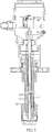
Fig. 3 is a cross sectional view of this invention. -
FIGS. 1A and1B are an embodiment of this invention. A sensing device has aprobe 10, acontrol module 20, avolume sensing module 30, athermal sensing module 40, anoutput module 50, and apower module 60. - The
probe 10 contains twomaterial electrodes 11 and athermal electrode 12. Thethermal electrode 12 contains multiplethermal sensors 121 as shown inFig. 2 . In this embodiment, thethermal electrode 12 is placed between the twomaterial electrodes 11 and is in the form of a long rod as shown inFig. 3 . The twomaterial electrodes 11 are manufactured by steel cable for transmitting signals, and provide better impact resistant ability and loading ability. - The
control module 20 contains at least one thermal signal input terminal, at least one volume signal input terminal, multiple signal output terminals, and a power input terminal. - The
volume sensing module 30 contains a firstsignal processing unit 31, a first analog-digital converter 32, and awaveform generating unit 33. An output terminal of the first analog-digital converter 32 is connected to the volume signal input terminal of thecontrol module 20. The firstsignal processing unit 31 processes a signal inputted from theprobe 10, and the signal is transmitted to thecontrol module 20 by the first analog-digital converter 32. Correct volume information can be calculated based on radio frequency admittance. Thewaveform generating unit 33 is controlled by thecontrol module 20, and outputs the signal to thematerial electrodes 11 of theprobe 10 for measurement based on radio frequency admittance. In this embodiment, thevolume sensing module 30 further includes ananalog signal isolator 34 and anisolated signal processor 35. Theisolated signal processor 35 is connected between theanalog signal isolator 34 and theprobe 10. Theisolated signal processor 35 removes noise from the signal transmitted from theprobe 10 to avoid misjudgment. Two input terminals of theanalog signal isolator 34 are respectively connected to an output terminal of theisolated signal processor 35 and an output terminal of thewaveform generating unit 33. Two output terminals of theanalog signal isolator 34 are respectively connected to an input terminal of theisolated signal processor 35 and an input terminal of the firstsignal processing unit 31. Theanalog signal isolator 34 can protect thevolume sensing module 30 from being damaged by a high voltage or a high current caused by an incorrect circuit connection. - The
thermal sensing module 40 contains a secondsignal processing unit 41, a second analog-digital converter 42, a switchingunit 43, and a detecting array 44. The detecting array 44 obtains a thermal signal from theprobe 10. The thermal signal is provided by thethermal sensor 121 of thethermal electrode 12, and is calculated and outputted by the secondsignal processing unit 41. An input terminal of the second analog-digital converter 42 is connected to an output terminal of the secondsignal processing unit 41, so the thermal signal is obtained from the secondsignal processing unit 41 and converted to a digital signal outputted to thecontrol module 20. The switchingunit 43 is controlled by thecontrol module 20 for outputting a signal to the detecting array 44 for adjusting thermal sensing sensitivity. In this embodiment, thethermal sensing module 40 further contains adigital signal isolator 45 which can protect thethermal sensing module 40 from being damaged by a high voltage or a high current caused by an incorrect circuit connection. - The
output module 50 has a signal input terminal and a signal output terminal. The signal input terminal is connected to part of the multiple signal output terminals ofcontrol module 20. In this embodiment, theoutput module 50 further contains ananalog output unit 51 and adigital output unit 52, so theoutput module 50 can, depending on requests, output signals to an external receiving terminal. Theoutput module 50 outputs signals that are conformed to an industry signal standard such as 0∼10 V or 0∼20 mA. - The
power module 60 contains at least one DC toDC converter 61 for providing working power to thecontrol module 20, thevolume sensing module 30, thethermal sensing module 40, and theoutput module 50. Thepower module 60 is controlled by thecontrol module 20 to provide a rated voltage to thematerial electrodes 11 of theprobe 10. - In this embodiment, the sensing device further contains a
user interface 70 and awireless transmission module 80. Theuser interface 70 contains adisplay unit 71 and aninput unit 72. Theinput unit 72 can be a keyboard or a touch panel operated by users to enter control instructions. Thedisplay 71 can show a current sensing situation or sensing information from the sensing device. Thewireless transmission module 80 can transmit data to an external computer or a central control console. - In this embodiment, the
material electrodes 11 of theprobe 10 function as an material sensing interface for thevolume sensing module 30, and detect material volume based on radio frequency admittance. When a rated voltage is applied at thematerial electrodes 11 and a triggering signal is generated by thewaveform generating unit 33, thevolume sensing module 30 detects a current deviation between thematerial electrodes 11 and a ground potential. A volume signal is generated from the triggering signal. The volume signal is converted to a digital signal and outputted to thecontrol module 20. Thecontrol module 20 converts the digital signal to obtain material volume based on radio frequency admittance. The current deviation usually correlates with material volume, a dielectric constant, thermal function, and especially frequency of a constant voltage. When a particular current deviation is measured, the particular current deviation is converted to the digital signal. Thecontrol module 20 converts the digital signal to obtain material volume based on radio frequency admittance. The multiplethermal sensors 121 are respectively placed from a top of thethermal electrode 12 to bottom of thethermal electrode 12, and are respectively connected to the detecting array 44 of thethermal sensing module 40. By said means, temperatures at each depth of the material can be detected, and situations at each depth of the material also can be promptly handled. - As stated above, the material volume and thermal information are respectively obtained by the
material electrodes 11 and thethermal electrode 12 of theprobe 10. The material volume and thermal information are respectively processed by thevolume sensing module 30 and thethermal sensing module 40, and both are transmitted to thecontrol module 20. Correct material information is calculated by thecontrol module 20. Then, the correct material information is transmitted to the external computer or the central control console by cable transmission or wireless transmission for monitoring. Thecontrol module 20 converts the digital signal to obtain material volume based on radio frequency admittance. The rated voltage is applied at thematerial electrodes 11. Thevolume sensing module 30 detects the current deviation between thematerial electrodes 11 and the ground potential. A storage amount of the material is calculated by thecontrol module 20 from the current deviation. Therefore, the material volume can be obtained by thecontrol module 20 and based on radio frequency admittance for detecting material depth or liquid-level. Even though the material is changed, the sensing device does not have to be changed and can keep on monitoring. Steel cable is used as the material of thematerial electrodes 11 of theprobe 10, and provides better impact resistant ability and loading ability, so the sensing device of this invention can detect material depth, liquid-level, and temperature.
Claims (5)
- A sensing device for detecting material depth, liquid-level, and temperature, the sensing device comprising a probe (10) comprising two material electrodes (11) and a thermal electrode (12) comprising multiple thermal sensors (121);a control module (20) comprising at least one thermal signal input terminal, at least one volume signal input terminal, multiple signal output terminals, and a power input terminal;a volume sensing module (30) comprising:a first analog-digital converter (32) having an output terminal connected to the volume signal input terminal of the control module (20);a first signal processing unit (31) processing a signal from the probe (10) and transmitting the signal to the control module (20) via the first analog-digital converter (32); anda waveform generating unit (33) controlled by the control module (20), and outputting a signal to the material electrodes (11) of the probe (10);a thermal sensing module (40) comprising:a second signal processing unit (41) processing a thermal signal from the thermal electrode (12) of the probe (10); anda second analog-digital converter (42) having an input terminal connected to an output terminal of the second signal processing unit (41), converting the thermal signal to a digital signal, and transmitting the digital signal to the control module (20);an output module (50) comprising:a signal input terminal connected to part of the multiple signal output terminals of the control module (20); anda signal output terminal; anda power module (60) comprising at least one DC to DC converter (61) for providing working power to the control module (20), the volume sensing module (30), the thermal sensing module (40), the probe (10), and the output module (50), wherein the sensing device is characterized in that:the waveform generating unit (33) outputs the signal to the material electrodes (11) of the probe (10) for measurement based on radio frequency admittance;the material electrodes (11) and the thermal electrode (12) of the probe (10) are in the form of long rods; the material electrodes (11) are manufactured by steel cable, the thermal electrode (12) is connected between the two material electrodes (11), and the thermal electrode (12) has multiple thermal sensors (121) placed from a top of the thermal electrode (12) to a bottom of the thermal electrode (12);the thermal sensing module (40) comprises a detecting array (44) and a switching unit (43), the detecting array (44) is connected to each thermal sensor (121) mounted on the thermal electrode (12), and the switching unit (43) is controlled by the control module (20) and outputs signals to the detecting array (44) for adjusting thermal sensing sensitivity;the volume sensing module (30) comprises an isolated signal processor (35) and an analog signal isolator (34), the isolated signal processor (35) is connected to the probe (10), the analog signal isolator (35) comprises two input terminals and two output terminals, the two input terminals of the analog signal isolator (34) are respectively connected to an output terminal of the isolated signal processor (35) and an output terminal of the waveform generating unit (33), the two output terminals of the analog signal isolator (34) are respectively connected to an input terminal of the isolated signal processor (35) and an input terminal of the first signal processing unit (31).
- The sensing device as claimed in claim 1, wherein the thermal sensing module (40) comprises a digital signal isolator (45).
- The sensing device as claimed in claim 1 or 2, wherein the sensing device further comprises:a wireless transmission module (80) transmitting data by a wireless transmission protocol; anda user interface (70) comprising a display unit (71) and an input unit (72).
- The sensing device as claimed in claim 3, wherein the input unit (72) is a keyboard.
- The sensing device as claimed in claim 3, wherein the input unit (72) is a touch panel.
Applications Claiming Priority (1)
| Application Number | Priority Date | Filing Date | Title |
|---|---|---|---|
| TW101101909A TWI440830B (en) | 2012-01-18 | 2012-01-18 | Liquid level sensor |
Publications (2)
| Publication Number | Publication Date |
|---|---|
| EP2618117A1 EP2618117A1 (en) | 2013-07-24 |
| EP2618117B1 true EP2618117B1 (en) | 2017-04-12 |
Family
ID=46085809
Family Applications (1)
| Application Number | Title | Priority Date | Filing Date |
|---|---|---|---|
| EP12167054.1A Not-in-force EP2618117B1 (en) | 2012-01-18 | 2012-05-08 | Sensing device for detecting material depth, liquid-level, and temperature |
Country Status (3)
| Country | Link |
|---|---|
| US (1) | US8950255B2 (en) |
| EP (1) | EP2618117B1 (en) |
| TW (1) | TWI440830B (en) |
Families Citing this family (13)
| Publication number | Priority date | Publication date | Assignee | Title |
|---|---|---|---|---|
| EP3051260B1 (en) * | 2013-08-16 | 2018-12-19 | Watgrid, Lda. | Intrusive level probe |
| TWI476378B (en) * | 2013-11-12 | 2015-03-11 | 桓達科技股份有限公司 | Level and temperature sensing device |
| TWI486560B (en) * | 2013-11-25 | 2015-06-01 | 桓達科技股份有限公司 | Cable level temperature sensor |
| CN104457909A (en) * | 2014-12-23 | 2015-03-25 | 上海雄风自控工程有限公司 | Intelligent radio frequency admittance controller |
| CN105222909B (en) * | 2015-09-21 | 2018-02-16 | 河北省电力勘测设计研究院 | Power Cable Joint Temperature computational methods |
| DE102018101206A1 (en) | 2018-01-19 | 2019-07-25 | Endress+Hauser SE+Co. KG | probe unit |
| US11614026B2 (en) | 2019-11-25 | 2023-03-28 | Wheeler Fleet Solutions, Co. | Interchangeable coolant sensor for vehicle applications and methods of manufacture and use thereof |
| US11703371B1 (en) | 2020-04-06 | 2023-07-18 | Devicesolutions | Bin material measurement |
| CN112577568B (en) * | 2020-11-02 | 2025-03-11 | 青蛙泵业股份有限公司 | A water level monitoring system for water source wells |
| CN112525293A (en) * | 2020-12-04 | 2021-03-19 | 上海朝辉压力仪器有限公司 | Wireless 4G-based capacitive oil level sensor |
| CN118103239A (en) * | 2021-10-15 | 2024-05-28 | 海拉有限双合股份公司 | Coolant tank, coolant guiding system and motor vehicle |
| CN115824352B (en) * | 2022-10-31 | 2024-05-17 | 淮阴工学院 | Self-adaptive digital radio frequency admittance level meter |
| US20250389573A1 (en) * | 2024-06-25 | 2025-12-25 | Nick Angelo | Liquid level sensing device |
Citations (1)
| Publication number | Priority date | Publication date | Assignee | Title |
|---|---|---|---|---|
| EP1811274A1 (en) * | 2006-01-19 | 2007-07-25 | Whirlpool Corporation | Water level measurement system |
Family Cites Families (8)
| Publication number | Priority date | Publication date | Assignee | Title |
|---|---|---|---|---|
| DE1909684C3 (en) * | 1968-03-01 | 1975-02-27 | Siemens Ag, 1000 Berlin U. 8000 Muenchen | Measuring cables for determining the temperature distribution of bulk goods or the like in silos |
| US4601201A (en) * | 1984-03-14 | 1986-07-22 | Tokyo Tatsuno Co., Ltd. | Liquid level and quantity measuring apparatus |
| US5156042A (en) * | 1987-07-17 | 1992-10-20 | Proeco, Inc. | Leak detector |
| US6701783B2 (en) * | 2000-09-12 | 2004-03-09 | Vega Grieshaber Kg | Device and a process for determining the positions of border areas between different mediums |
| WO2004017025A1 (en) * | 2002-08-13 | 2004-02-26 | Vega Grieshaber Kg | System for the production of a modular structure for the determination of a physical process variable and standardised components |
| US6959599B2 (en) * | 2003-04-10 | 2005-11-01 | Robert Feldstein | Level detector for storage tanks for fluids |
| DE102004009643A1 (en) * | 2004-02-27 | 2005-09-15 | Fafnir Gmbh | Ventilation mast monitoring system for gas stations |
| CN102200463A (en) * | 2011-03-23 | 2011-09-28 | 泰州市瑞芝电子有限公司 | Liquid level linear measurement method based on impedance measurement |
-
2012
- 2012-01-18 TW TW101101909A patent/TWI440830B/en not_active IP Right Cessation
- 2012-05-03 US US13/463,089 patent/US8950255B2/en active Active
- 2012-05-08 EP EP12167054.1A patent/EP2618117B1/en not_active Not-in-force
Patent Citations (1)
| Publication number | Priority date | Publication date | Assignee | Title |
|---|---|---|---|---|
| EP1811274A1 (en) * | 2006-01-19 | 2007-07-25 | Whirlpool Corporation | Water level measurement system |
Also Published As
| Publication number | Publication date |
|---|---|
| US8950255B2 (en) | 2015-02-10 |
| US20130182742A1 (en) | 2013-07-18 |
| TW201331557A (en) | 2013-08-01 |
| TWI440830B (en) | 2014-06-11 |
| EP2618117A1 (en) | 2013-07-24 |
Similar Documents
| Publication | Publication Date | Title |
|---|---|---|
| US8950255B2 (en) | Sensing device for detecting material depth, liquid-level, and temperature | |
| EP3567380B1 (en) | Non-contact dc voltage measurement device with oscillating sensor | |
| US10422680B2 (en) | Method for monitoring at least one media-specific property of a medium | |
| CN104634385B (en) | Level and Temperature Sensing Devices | |
| JP6125650B2 (en) | Hot stick power analyzer | |
| TW201830032A (en) | Non-contact voltage measurement system using multiple capacitors | |
| TWI780327B (en) | Multi-sensor scanner configuration for non-contact voltage measurement devices | |
| CN101261148A (en) | Pressure type digital level sensor and its measuring method | |
| US10145718B2 (en) | Level gauge | |
| WO2023078923A1 (en) | Circuit for impedance measurements | |
| WO2020219197A1 (en) | Dual polarity mutual capacitive liquid sensing | |
| US20070000320A1 (en) | Bin level monitor | |
| JP2004093565A (en) | Filling level measuring apparatus | |
| JP6498709B2 (en) | Detection apparatus and substance detection method | |
| US11561250B2 (en) | Electrostatic charge buildup and electrostatic discharge monitoring system and method | |
| CN111623808A (en) | Capacitive sensor attached to a container capable of containing a substance | |
| EP3153869B1 (en) | Device and method for measuring the power consumption, contactless device and method for measuring power supply status | |
| KR102060254B1 (en) | Load Cell And Multi Load Cell | |
| TWI613441B (en) | Sensing apparatus and material sensing method | |
| JP2010237028A (en) | Humidity measuring device | |
| US20170003237A1 (en) | Inductive conductivity sensor for measuring the specific electrical conductivity of a medium | |
| JP4255926B2 (en) | Strain and temperature measuring device | |
| CN108204845B (en) | Sensing device and substance sensing method | |
| KR100501496B1 (en) | Electrical Micrometer having a Wireless sending function of Measuring Data | |
| CN202049393U (en) | Intelligent RF admittance material level controller |
Legal Events
| Date | Code | Title | Description |
|---|---|---|---|
| PUAI | Public reference made under article 153(3) epc to a published international application that has entered the european phase |
Free format text: ORIGINAL CODE: 0009012 |
|
| AK | Designated contracting states |
Kind code of ref document: A1 Designated state(s): AL AT BE BG CH CY CZ DE DK EE ES FI FR GB GR HR HU IE IS IT LI LT LU LV MC MK MT NL NO PL PT RO RS SE SI SK SM TR |
|
| AX | Request for extension of the european patent |
Extension state: BA ME |
|
| 17P | Request for examination filed |
Effective date: 20140113 |
|
| RBV | Designated contracting states (corrected) |
Designated state(s): AL AT BE BG CH CY CZ DE DK EE ES FI FR GB GR HR HU IE IS IT LI LT LU LV MC MK MT NL NO PL PT RO RS SE SI SK SM TR |
|
| GRAP | Despatch of communication of intention to grant a patent |
Free format text: ORIGINAL CODE: EPIDOSNIGR1 |
|
| INTG | Intention to grant announced |
Effective date: 20161103 |
|
| RIN1 | Information on inventor provided before grant (corrected) |
Inventor name: CHEN, CHING-JUI Inventor name: CHANG, CHENG-LUN Inventor name: CHANG, LIANG-CHI Inventor name: CHENG, CHAO-KAI |
|
| GRAS | Grant fee paid |
Free format text: ORIGINAL CODE: EPIDOSNIGR3 |
|
| GRAA | (expected) grant |
Free format text: ORIGINAL CODE: 0009210 |
|
| AK | Designated contracting states |
Kind code of ref document: B1 Designated state(s): AL AT BE BG CH CY CZ DE DK EE ES FI FR GB GR HR HU IE IS IT LI LT LU LV MC MK MT NL NO PL PT RO RS SE SI SK SM TR |
|
| REG | Reference to a national code |
Ref country code: GB Ref legal event code: FG4D |
|
| REG | Reference to a national code |
Ref country code: CH Ref legal event code: EP |
|
| REG | Reference to a national code |
Ref country code: IE Ref legal event code: FG4D |
|
| REG | Reference to a national code |
Ref country code: AT Ref legal event code: REF Ref document number: 884378 Country of ref document: AT Kind code of ref document: T Effective date: 20170515 |
|
| REG | Reference to a national code |
Ref country code: DE Ref legal event code: R096 Ref document number: 602012030973 Country of ref document: DE |
|
| REG | Reference to a national code |
Ref country code: SE Ref legal event code: TRGR |
|
| PGFP | Annual fee paid to national office [announced via postgrant information from national office to epo] |
Ref country code: GB Payment date: 20170508 Year of fee payment: 6 |
|
| REG | Reference to a national code |
Ref country code: NL Ref legal event code: MP Effective date: 20170412 |
|
| REG | Reference to a national code |
Ref country code: LT Ref legal event code: MG4D |
|
| PGFP | Annual fee paid to national office [announced via postgrant information from national office to epo] |
Ref country code: SE Payment date: 20170530 Year of fee payment: 6 |
|
| REG | Reference to a national code |
Ref country code: AT Ref legal event code: MK05 Ref document number: 884378 Country of ref document: AT Kind code of ref document: T Effective date: 20170412 |
|
| PG25 | Lapsed in a contracting state [announced via postgrant information from national office to epo] |
Ref country code: NL Free format text: LAPSE BECAUSE OF FAILURE TO SUBMIT A TRANSLATION OF THE DESCRIPTION OR TO PAY THE FEE WITHIN THE PRESCRIBED TIME-LIMIT Effective date: 20170412 |
|
| PG25 | Lapsed in a contracting state [announced via postgrant information from national office to epo] |
Ref country code: FI Free format text: LAPSE BECAUSE OF FAILURE TO SUBMIT A TRANSLATION OF THE DESCRIPTION OR TO PAY THE FEE WITHIN THE PRESCRIBED TIME-LIMIT Effective date: 20170412 Ref country code: LT Free format text: LAPSE BECAUSE OF FAILURE TO SUBMIT A TRANSLATION OF THE DESCRIPTION OR TO PAY THE FEE WITHIN THE PRESCRIBED TIME-LIMIT Effective date: 20170412 Ref country code: ES Free format text: LAPSE BECAUSE OF FAILURE TO SUBMIT A TRANSLATION OF THE DESCRIPTION OR TO PAY THE FEE WITHIN THE PRESCRIBED TIME-LIMIT Effective date: 20170412 Ref country code: NO Free format text: LAPSE BECAUSE OF FAILURE TO SUBMIT A TRANSLATION OF THE DESCRIPTION OR TO PAY THE FEE WITHIN THE PRESCRIBED TIME-LIMIT Effective date: 20170712 Ref country code: HR Free format text: LAPSE BECAUSE OF FAILURE TO SUBMIT A TRANSLATION OF THE DESCRIPTION OR TO PAY THE FEE WITHIN THE PRESCRIBED TIME-LIMIT Effective date: 20170412 Ref country code: GR Free format text: LAPSE BECAUSE OF FAILURE TO SUBMIT A TRANSLATION OF THE DESCRIPTION OR TO PAY THE FEE WITHIN THE PRESCRIBED TIME-LIMIT Effective date: 20170713 Ref country code: AT Free format text: LAPSE BECAUSE OF FAILURE TO SUBMIT A TRANSLATION OF THE DESCRIPTION OR TO PAY THE FEE WITHIN THE PRESCRIBED TIME-LIMIT Effective date: 20170412 |
|
| PG25 | Lapsed in a contracting state [announced via postgrant information from national office to epo] |
Ref country code: LV Free format text: LAPSE BECAUSE OF FAILURE TO SUBMIT A TRANSLATION OF THE DESCRIPTION OR TO PAY THE FEE WITHIN THE PRESCRIBED TIME-LIMIT Effective date: 20170412 Ref country code: PL Free format text: LAPSE BECAUSE OF FAILURE TO SUBMIT A TRANSLATION OF THE DESCRIPTION OR TO PAY THE FEE WITHIN THE PRESCRIBED TIME-LIMIT Effective date: 20170412 Ref country code: RS Free format text: LAPSE BECAUSE OF FAILURE TO SUBMIT A TRANSLATION OF THE DESCRIPTION OR TO PAY THE FEE WITHIN THE PRESCRIBED TIME-LIMIT Effective date: 20170412 Ref country code: IS Free format text: LAPSE BECAUSE OF FAILURE TO SUBMIT A TRANSLATION OF THE DESCRIPTION OR TO PAY THE FEE WITHIN THE PRESCRIBED TIME-LIMIT Effective date: 20170812 Ref country code: BG Free format text: LAPSE BECAUSE OF FAILURE TO SUBMIT A TRANSLATION OF THE DESCRIPTION OR TO PAY THE FEE WITHIN THE PRESCRIBED TIME-LIMIT Effective date: 20170712 |
|
| REG | Reference to a national code |
Ref country code: CH Ref legal event code: PL |
|
| REG | Reference to a national code |
Ref country code: DE Ref legal event code: R097 Ref document number: 602012030973 Country of ref document: DE |
|
| PG25 | Lapsed in a contracting state [announced via postgrant information from national office to epo] |
Ref country code: MC Free format text: LAPSE BECAUSE OF FAILURE TO SUBMIT A TRANSLATION OF THE DESCRIPTION OR TO PAY THE FEE WITHIN THE PRESCRIBED TIME-LIMIT Effective date: 20170412 Ref country code: CZ Free format text: LAPSE BECAUSE OF FAILURE TO SUBMIT A TRANSLATION OF THE DESCRIPTION OR TO PAY THE FEE WITHIN THE PRESCRIBED TIME-LIMIT Effective date: 20170412 Ref country code: EE Free format text: LAPSE BECAUSE OF FAILURE TO SUBMIT A TRANSLATION OF THE DESCRIPTION OR TO PAY THE FEE WITHIN THE PRESCRIBED TIME-LIMIT Effective date: 20170412 Ref country code: DK Free format text: LAPSE BECAUSE OF FAILURE TO SUBMIT A TRANSLATION OF THE DESCRIPTION OR TO PAY THE FEE WITHIN THE PRESCRIBED TIME-LIMIT Effective date: 20170412 Ref country code: SK Free format text: LAPSE BECAUSE OF FAILURE TO SUBMIT A TRANSLATION OF THE DESCRIPTION OR TO PAY THE FEE WITHIN THE PRESCRIBED TIME-LIMIT Effective date: 20170412 Ref country code: RO Free format text: LAPSE BECAUSE OF FAILURE TO SUBMIT A TRANSLATION OF THE DESCRIPTION OR TO PAY THE FEE WITHIN THE PRESCRIBED TIME-LIMIT Effective date: 20170412 |
|
| PLBE | No opposition filed within time limit |
Free format text: ORIGINAL CODE: 0009261 |
|
| STAA | Information on the status of an ep patent application or granted ep patent |
Free format text: STATUS: NO OPPOSITION FILED WITHIN TIME LIMIT |
|
| REG | Reference to a national code |
Ref country code: IE Ref legal event code: MM4A |
|
| PG25 | Lapsed in a contracting state [announced via postgrant information from national office to epo] |
Ref country code: SM Free format text: LAPSE BECAUSE OF FAILURE TO SUBMIT A TRANSLATION OF THE DESCRIPTION OR TO PAY THE FEE WITHIN THE PRESCRIBED TIME-LIMIT Effective date: 20170412 Ref country code: IT Free format text: LAPSE BECAUSE OF FAILURE TO SUBMIT A TRANSLATION OF THE DESCRIPTION OR TO PAY THE FEE WITHIN THE PRESCRIBED TIME-LIMIT Effective date: 20170412 Ref country code: CH Free format text: LAPSE BECAUSE OF NON-PAYMENT OF DUE FEES Effective date: 20170531 Ref country code: LI Free format text: LAPSE BECAUSE OF NON-PAYMENT OF DUE FEES Effective date: 20170531 |
|
| REG | Reference to a national code |
Ref country code: FR Ref legal event code: ST Effective date: 20180131 |
|
| 26N | No opposition filed |
Effective date: 20180115 |
|
| PG25 | Lapsed in a contracting state [announced via postgrant information from national office to epo] |
Ref country code: LU Free format text: LAPSE BECAUSE OF NON-PAYMENT OF DUE FEES Effective date: 20170508 |
|
| REG | Reference to a national code |
Ref country code: BE Ref legal event code: MM Effective date: 20170531 |
|
| PG25 | Lapsed in a contracting state [announced via postgrant information from national office to epo] |
Ref country code: IE Free format text: LAPSE BECAUSE OF NON-PAYMENT OF DUE FEES Effective date: 20170508 |
|
| PG25 | Lapsed in a contracting state [announced via postgrant information from national office to epo] |
Ref country code: SI Free format text: LAPSE BECAUSE OF FAILURE TO SUBMIT A TRANSLATION OF THE DESCRIPTION OR TO PAY THE FEE WITHIN THE PRESCRIBED TIME-LIMIT Effective date: 20170412 Ref country code: FR Free format text: LAPSE BECAUSE OF NON-PAYMENT OF DUE FEES Effective date: 20170612 |
|
| PG25 | Lapsed in a contracting state [announced via postgrant information from national office to epo] |
Ref country code: BE Free format text: LAPSE BECAUSE OF NON-PAYMENT OF DUE FEES Effective date: 20170531 |
|
| PG25 | Lapsed in a contracting state [announced via postgrant information from national office to epo] |
Ref country code: MT Free format text: LAPSE BECAUSE OF NON-PAYMENT OF DUE FEES Effective date: 20170508 |
|
| REG | Reference to a national code |
Ref country code: SE Ref legal event code: EUG |
|
| GBPC | Gb: european patent ceased through non-payment of renewal fee |
Effective date: 20180508 |
|
| PG25 | Lapsed in a contracting state [announced via postgrant information from national office to epo] |
Ref country code: SE Free format text: LAPSE BECAUSE OF NON-PAYMENT OF DUE FEES Effective date: 20180509 |
|
| PG25 | Lapsed in a contracting state [announced via postgrant information from national office to epo] |
Ref country code: GB Free format text: LAPSE BECAUSE OF NON-PAYMENT OF DUE FEES Effective date: 20180508 |
|
| PG25 | Lapsed in a contracting state [announced via postgrant information from national office to epo] |
Ref country code: HU Free format text: LAPSE BECAUSE OF FAILURE TO SUBMIT A TRANSLATION OF THE DESCRIPTION OR TO PAY THE FEE WITHIN THE PRESCRIBED TIME-LIMIT; INVALID AB INITIO Effective date: 20120508 |
|
| PG25 | Lapsed in a contracting state [announced via postgrant information from national office to epo] |
Ref country code: CY Free format text: LAPSE BECAUSE OF NON-PAYMENT OF DUE FEES Effective date: 20170412 |
|
| PG25 | Lapsed in a contracting state [announced via postgrant information from national office to epo] |
Ref country code: MK Free format text: LAPSE BECAUSE OF FAILURE TO SUBMIT A TRANSLATION OF THE DESCRIPTION OR TO PAY THE FEE WITHIN THE PRESCRIBED TIME-LIMIT Effective date: 20170412 |
|
| PG25 | Lapsed in a contracting state [announced via postgrant information from national office to epo] |
Ref country code: TR Free format text: LAPSE BECAUSE OF FAILURE TO SUBMIT A TRANSLATION OF THE DESCRIPTION OR TO PAY THE FEE WITHIN THE PRESCRIBED TIME-LIMIT Effective date: 20170412 |
|
| PG25 | Lapsed in a contracting state [announced via postgrant information from national office to epo] |
Ref country code: PT Free format text: LAPSE BECAUSE OF FAILURE TO SUBMIT A TRANSLATION OF THE DESCRIPTION OR TO PAY THE FEE WITHIN THE PRESCRIBED TIME-LIMIT Effective date: 20170412 |
|
| PG25 | Lapsed in a contracting state [announced via postgrant information from national office to epo] |
Ref country code: AL Free format text: LAPSE BECAUSE OF FAILURE TO SUBMIT A TRANSLATION OF THE DESCRIPTION OR TO PAY THE FEE WITHIN THE PRESCRIBED TIME-LIMIT Effective date: 20170412 |
|
| PGFP | Annual fee paid to national office [announced via postgrant information from national office to epo] |
Ref country code: DE Payment date: 20240402 Year of fee payment: 13 |
|
| REG | Reference to a national code |
Ref country code: DE Ref legal event code: R119 Ref document number: 602012030973 Country of ref document: DE |
|
| PG25 | Lapsed in a contracting state [announced via postgrant information from national office to epo] |
Ref country code: DE Free format text: LAPSE BECAUSE OF NON-PAYMENT OF DUE FEES Effective date: 20251202 |