EP2617980A2 - Gas turbine engines - Google Patents
Gas turbine engines Download PDFInfo
- Publication number
- EP2617980A2 EP2617980A2 EP13151205.5A EP13151205A EP2617980A2 EP 2617980 A2 EP2617980 A2 EP 2617980A2 EP 13151205 A EP13151205 A EP 13151205A EP 2617980 A2 EP2617980 A2 EP 2617980A2
- Authority
- EP
- European Patent Office
- Prior art keywords
- gas turbine
- spool
- turbine engine
- fan
- recited
- Prior art date
- Legal status (The legal status is an assumption and is not a legal conclusion. Google has not performed a legal analysis and makes no representation as to the accuracy of the status listed.)
- Granted
Links
Images




Classifications
-
- F—MECHANICAL ENGINEERING; LIGHTING; HEATING; WEAPONS; BLASTING
- F02—COMBUSTION ENGINES; HOT-GAS OR COMBUSTION-PRODUCT ENGINE PLANTS
- F02K—JET-PROPULSION PLANTS
- F02K3/00—Plants including a gas turbine driving a compressor or a ducted fan
- F02K3/02—Plants including a gas turbine driving a compressor or a ducted fan in which part of the working fluid by-passes the turbine and combustion chamber
- F02K3/04—Plants including a gas turbine driving a compressor or a ducted fan in which part of the working fluid by-passes the turbine and combustion chamber the plant including ducted fans, i.e. fans with high volume, low pressure outputs, for augmenting the jet thrust, e.g. of double-flow type
- F02K3/075—Plants including a gas turbine driving a compressor or a ducted fan in which part of the working fluid by-passes the turbine and combustion chamber the plant including ducted fans, i.e. fans with high volume, low pressure outputs, for augmenting the jet thrust, e.g. of double-flow type controlling flow ratio between flows
-
- F—MECHANICAL ENGINEERING; LIGHTING; HEATING; WEAPONS; BLASTING
- F01—MACHINES OR ENGINES IN GENERAL; ENGINE PLANTS IN GENERAL; STEAM ENGINES
- F01D—NON-POSITIVE DISPLACEMENT MACHINES OR ENGINES, e.g. STEAM TURBINES
- F01D1/00—Non-positive-displacement machines or engines, e.g. steam turbines
- F01D1/02—Non-positive-displacement machines or engines, e.g. steam turbines with stationary working-fluid guiding means and bladed or like rotor, e.g. multi-bladed impulse steam turbines
- F01D1/023—Non-positive-displacement machines or engines, e.g. steam turbines with stationary working-fluid guiding means and bladed or like rotor, e.g. multi-bladed impulse steam turbines the working-fluid being divided into several separate flows ; several separate fluid flows being united in a single flow; the machine or engine having provision for two or more different possible fluid flow paths
-
- F—MECHANICAL ENGINEERING; LIGHTING; HEATING; WEAPONS; BLASTING
- F01—MACHINES OR ENGINES IN GENERAL; ENGINE PLANTS IN GENERAL; STEAM ENGINES
- F01D—NON-POSITIVE DISPLACEMENT MACHINES OR ENGINES, e.g. STEAM TURBINES
- F01D17/00—Regulating or controlling by varying flow
-
- F—MECHANICAL ENGINEERING; LIGHTING; HEATING; WEAPONS; BLASTING
- F01—MACHINES OR ENGINES IN GENERAL; ENGINE PLANTS IN GENERAL; STEAM ENGINES
- F01D—NON-POSITIVE DISPLACEMENT MACHINES OR ENGINES, e.g. STEAM TURBINES
- F01D19/00—Starting of machines or engines; Regulating, controlling, or safety means in connection therewith
-
- F—MECHANICAL ENGINEERING; LIGHTING; HEATING; WEAPONS; BLASTING
- F01—MACHINES OR ENGINES IN GENERAL; ENGINE PLANTS IN GENERAL; STEAM ENGINES
- F01D—NON-POSITIVE DISPLACEMENT MACHINES OR ENGINES, e.g. STEAM TURBINES
- F01D9/00—Stators
- F01D9/02—Nozzles; Nozzle boxes; Stator blades; Guide conduits, e.g. individual nozzles
- F01D9/04—Nozzles; Nozzle boxes; Stator blades; Guide conduits, e.g. individual nozzles forming ring or sector
-
- F—MECHANICAL ENGINEERING; LIGHTING; HEATING; WEAPONS; BLASTING
- F01—MACHINES OR ENGINES IN GENERAL; ENGINE PLANTS IN GENERAL; STEAM ENGINES
- F01D—NON-POSITIVE DISPLACEMENT MACHINES OR ENGINES, e.g. STEAM TURBINES
- F01D9/00—Stators
- F01D9/06—Fluid supply conduits to nozzles or the like
- F01D9/065—Fluid supply or removal conduits traversing the working fluid flow, e.g. for lubrication-, cooling-, or sealing fluids
-
- F—MECHANICAL ENGINEERING; LIGHTING; HEATING; WEAPONS; BLASTING
- F04—POSITIVE - DISPLACEMENT MACHINES FOR LIQUIDS; PUMPS FOR LIQUIDS OR ELASTIC FLUIDS
- F04D—NON-POSITIVE-DISPLACEMENT PUMPS
- F04D27/00—Control, e.g. regulation, of pumps, pumping installations or pumping systems specially adapted for elastic fluids
- F04D27/002—Control, e.g. regulation, of pumps, pumping installations or pumping systems specially adapted for elastic fluids by varying geometry within the pumps, e.g. by adjusting vanes
-
- F—MECHANICAL ENGINEERING; LIGHTING; HEATING; WEAPONS; BLASTING
- F04—POSITIVE - DISPLACEMENT MACHINES FOR LIQUIDS; PUMPS FOR LIQUIDS OR ELASTIC FLUIDS
- F04D—NON-POSITIVE-DISPLACEMENT PUMPS
- F04D27/00—Control, e.g. regulation, of pumps, pumping installations or pumping systems specially adapted for elastic fluids
- F04D27/009—Control, e.g. regulation, of pumps, pumping installations or pumping systems specially adapted for elastic fluids by bleeding, by passing or recycling fluid
-
- F—MECHANICAL ENGINEERING; LIGHTING; HEATING; WEAPONS; BLASTING
- F04—POSITIVE - DISPLACEMENT MACHINES FOR LIQUIDS; PUMPS FOR LIQUIDS OR ELASTIC FLUIDS
- F04D—NON-POSITIVE-DISPLACEMENT PUMPS
- F04D29/00—Details, component parts, or accessories
- F04D29/40—Casings; Connections of working fluid
- F04D29/52—Casings; Connections of working fluid for axial pumps
- F04D29/522—Casings; Connections of working fluid for axial pumps especially adapted for elastic fluid pumps
- F04D29/524—Casings; Connections of working fluid for axial pumps especially adapted for elastic fluid pumps shiftable members for obturating part of the flow path
-
- F—MECHANICAL ENGINEERING; LIGHTING; HEATING; WEAPONS; BLASTING
- F05—INDEXING SCHEMES RELATING TO ENGINES OR PUMPS IN VARIOUS SUBCLASSES OF CLASSES F01-F04
- F05D—INDEXING SCHEME FOR ASPECTS RELATING TO NON-POSITIVE-DISPLACEMENT MACHINES OR ENGINES, GAS-TURBINES OR JET-PROPULSION PLANTS
- F05D2220/00—Application
- F05D2220/30—Application in turbines
- F05D2220/32—Application in turbines in gas turbines
- F05D2220/323—Application in turbines in gas turbines for aircraft propulsion, e.g. jet engines
-
- F—MECHANICAL ENGINEERING; LIGHTING; HEATING; WEAPONS; BLASTING
- F05—INDEXING SCHEMES RELATING TO ENGINES OR PUMPS IN VARIOUS SUBCLASSES OF CLASSES F01-F04
- F05D—INDEXING SCHEME FOR ASPECTS RELATING TO NON-POSITIVE-DISPLACEMENT MACHINES OR ENGINES, GAS-TURBINES OR JET-PROPULSION PLANTS
- F05D2240/00—Components
- F05D2240/10—Stators
- F05D2240/12—Fluid guiding means, e.g. vanes
-
- F—MECHANICAL ENGINEERING; LIGHTING; HEATING; WEAPONS; BLASTING
- F05—INDEXING SCHEMES RELATING TO ENGINES OR PUMPS IN VARIOUS SUBCLASSES OF CLASSES F01-F04
- F05D—INDEXING SCHEME FOR ASPECTS RELATING TO NON-POSITIVE-DISPLACEMENT MACHINES OR ENGINES, GAS-TURBINES OR JET-PROPULSION PLANTS
- F05D2250/00—Geometry
- F05D2250/30—Arrangement of components
- F05D2250/35—Arrangement of components rotated
-
- F—MECHANICAL ENGINEERING; LIGHTING; HEATING; WEAPONS; BLASTING
- F05—INDEXING SCHEMES RELATING TO ENGINES OR PUMPS IN VARIOUS SUBCLASSES OF CLASSES F01-F04
- F05D—INDEXING SCHEME FOR ASPECTS RELATING TO NON-POSITIVE-DISPLACEMENT MACHINES OR ENGINES, GAS-TURBINES OR JET-PROPULSION PLANTS
- F05D2250/00—Geometry
- F05D2250/40—Movement of components
- F05D2250/41—Movement of components with one degree of freedom
- F05D2250/411—Movement of components with one degree of freedom in rotation
-
- F—MECHANICAL ENGINEERING; LIGHTING; HEATING; WEAPONS; BLASTING
- F05—INDEXING SCHEMES RELATING TO ENGINES OR PUMPS IN VARIOUS SUBCLASSES OF CLASSES F01-F04
- F05D—INDEXING SCHEME FOR ASPECTS RELATING TO NON-POSITIVE-DISPLACEMENT MACHINES OR ENGINES, GAS-TURBINES OR JET-PROPULSION PLANTS
- F05D2250/00—Geometry
- F05D2250/90—Variable geometry
-
- Y—GENERAL TAGGING OF NEW TECHNOLOGICAL DEVELOPMENTS; GENERAL TAGGING OF CROSS-SECTIONAL TECHNOLOGIES SPANNING OVER SEVERAL SECTIONS OF THE IPC; TECHNICAL SUBJECTS COVERED BY FORMER USPC CROSS-REFERENCE ART COLLECTIONS [XRACs] AND DIGESTS
- Y02—TECHNOLOGIES OR APPLICATIONS FOR MITIGATION OR ADAPTATION AGAINST CLIMATE CHANGE
- Y02T—CLIMATE CHANGE MITIGATION TECHNOLOGIES RELATED TO TRANSPORTATION
- Y02T50/00—Aeronautics or air transport
- Y02T50/60—Efficient propulsion technologies, e.g. for aircraft
Definitions
- the present disclosure relates to gas turbine engines, and more particularly to a start system and method therefor.
- Gas turbine engines are typically started through the high spool with an air turbine starter or electric starter/generator which drives a towershaft through a gearbox. In flight, accessories and the generator are driven from this high-spool-mounted gearbox. In such an arrangement, horsepower is extracted from the high spool, which may debit high compressor stability.
- one challenge in start systems for gas turbine engines concerns the design of an operable system, within the available space in the gas turbine engine, to improve compressor stability.
- a gas turbine engine includes a high spool along an engine axis, the high spool operable to communicate a core airflow through a core flow path.
- a fan section is operable to communicate an airflow into a secondary flow path and the core flow path.
- a low spool is located along the engine axis to drive the fan section.
- a flow control mechanism is operable to direct at least a portion of the airflow from the secondary flow path into the core flow path.
- the flow control mechanism is movable between an open position and a closed position.
- the flow control mechanism is a fan duct blocker ring.
- the flow control mechanism is a nozzle.
- a further embodiment of the foregoing gas turbine engine includes a starter/generator connected to the low spool.
- the starter/generator is forward of the low spool.
- the starter/generator is aft of the low spool.
- the starter/generator is driven by the low spool through a towershaft.
- the high spool along the engine axis with a high pressure compressor section and a high pressure turbine section, the high pressure turbine section includes a variable guide vane.
- the fan section includes a variable pitch fan blade.
- the fan section includes a variable pitch vane.
- the low spool drives the fan section through a geared architecture.
- a method of operating a gas turbine engine gas turbine engine includes driving a low spool to generate a fan airflow from a fan section connected to the low spool and modulating a flow control mechanism to direct at least a portion of the fan airflow from a secondary flow path into a core flow path to drive a high spool.
- no accessory gearbox is driven by the high spool.
- a further embodiment of the foregoing method includes rotating the high spool in a direction opposite that of the low spool.
- a further embodiment of the foregoing method includes driving the fan section through a geared architecture driven by the low spool.
- a further embodiment of the foregoing method includes driving the low spool with a starter/generator.
- a further embodiment of the foregoing method includes driving a constant speed transmission with the low spool.
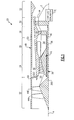
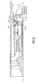
- FIG. 1 schematically illustrates a gas turbine engine 20.
- the gas turbine engine 20 is disclosed herein as a two-spool low bypass turbofan that generally includes a fan section 22, a high pressure compressor section (HPC) 24, a combustor section 26, a high pressure turbine section (HPT) 28, a low pressure turbine section (LPT) 30, and a nozzle section 32.
- Additional sections may include an augmentor section 34 among other systems or features such as a geared architecture.
- the sections are defined along a central longitudinal engine axis X.
- the fan section 22 and the LPT 30 are coupled by a first shaft 36 to define a low spool 38.
- the HPC 24, the combustor section 26 and the HPT 28 are generally referred to as an engine core.
- the HPC 24 and the HPT 28 are coupled by a second shaft 40 to define a high spool 42.
- the low spool 38 and the high spool 42 counter-rotate about axis X.
- the low spool 38 drives the fan section 22 either directly or through a geared architecture 38G (illustrated schematically) to drive a fan 44 such as a multi-stage fan with a first fan stage 44A and a second fan stage 44B, at a lower speed than the low spool 38.
- a low pressure compressor may alternatively or additionally be coupled to the first shaft 36 of the low spool 38.
- An engine case structure 48 generally includes an outer case structure 50, an intermediate case structure 52 and an inner case structure 54. It should be understood that various structures individual or collectively within the engine may define the case structures 50, 52, 54 to essentially define an exoskeleton that supports the spools 38, 42 for rotation therein.
- the outer case structure 50 and the intermediate case structure 52 define a generally annular secondary flow path 56.
- the intermediate case structure 52 and the inner case structure 54 define a core flow path 58 radially within the secondary flow path 56.
- a starter/generator 70 which, for example, may be in the Megawatt class for military weapon systems, or in the kilowatt class for civilian and military "all-electric" aircraft as well as others, is connected to the low spool 38.
- the starter/generator 70 is located aft of the LPT 30 within a tail cone T.
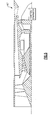
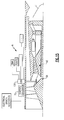
- the starter/generator 70 may be located within a fan hub 22H ( Figure 2 ) or connected forward of the low spool 38 through a forward power take off shaft 22S ( Figure 3 ) as well as in other locations.
- Air which enters the fan section 22 is divided between a core airflow and a fan airflow.
- the core airflow passes through the HPC 24, the combustor section 26, the HPT 28, the LPT 30 then the augmentor section 34 where fuel may be selectively injected and burned to generate additional thrust through the nozzle section 32.
- the fan section 22 communicates the fan airflow into the secondary flow path 56 as well as the core flow path 58 as the fan 44 is upstream of a split 52S between the secondary flow path 56 and the core flow path 58.
- the fan airflow may be utilized for a multiple of purposes to include, for example, cooling, pressurization and VSTOL operations.
- the fan airflow passes through an annulus defined by the outer case structure 50 and the intermediate case structure 52 then may be at least partially injected into the core flow adjacent the nozzle section 32.
- the nozzle section 32 receives flow from both the secondary flow path 56 and the core flow path 58. It should be understood that various fixed, variable, convergent/divergent, two-dimensional and three-dimensional nozzle systems as well as Variable Area Fan Nacelle (VAFN) may be utilized herewith.
- VAFN Variable Area Fan Nacelle
- the fan airflow as defined herein is any airflow different from the primary combustion gas core airflow through the engine core and may otherwise be described as secondary airflow or bypass air flow. Although depicted as an augmented low bypass gas turbine engine with a bypass ratio of approximately 0.7 in the disclosed non-limiting embodiment, it should be appreciated that the concepts described herein are applicable to other gas turbine engines such as high bypass engines with a VAFN.
- the fan airflow is selectively communicated through a flow control mechanism 60 into the secondary flow path 56.
- the flow control mechanism 60 may include various structures such as rotationally variable splitter vanes, pneumatic or mechanical operated blocker doors, or other structures that operate as a choke point to define a variable area throat and selectively control flow into the secondary flow path 56 such that a selective percentage of flow from the fan section 22 is divided between the secondary flow path 56 and the core flow path 58.
- the flow control mechanism 60 in one, disclosed, non-limiting embodiment, is a fan duct blocker to divert flow from the secondary flow path 56.
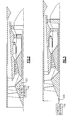
- the fan duct blocker is a two-piece vane ring 62 with a static ring 64 and a movable ring 66 which is selectively rotatable relative to the static ring 64 ( Figure 5 ).
- the rings 64, 66 are in line to form an aerodynamic shape that causes little pressure drop in the secondary flow path 56.
- the movable ring 66 is rotated such that the rings 64, 66 are staggered to form a wall to redirect a percentage of the fan airflow into the core flow path 58. It should be appreciated that all or a percentage of the fan airflow may be directed into the core flow path 58 through selective operation of the flow control mechanism 60.
- VAFN Variable Area Fan Nozzle
- the nozzle section 32 may include a separate core nozzle 32C such as in a low bypass engine or variable cycle architecture.
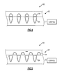
- a logic diagram for a start mode algorithm 200 is schematically illustrated.
- the functions of the algorithm 200 are disclosed in terms of a block diagram. It should be understood by those skilled in the art with the benefit of this disclosure that these functions may be enacted in either dedicated hardware circuitry or programmed software routines capable of execution in a microprocessor based electronics control embodiment.
- a module 202 may be utilized to execute the start mode algorithm 200.
- the module 202 may be an engine FADEC, a portion of a flight control computer, a portion of a central vehicle control, an interactive vehicle dynamics simulator unit or other system.
- the module typically includes a processor; a memory and an interface.
- the processor may be any type of known microprocessor having desired performance characteristics.
- the memory may be computer readable medium which stores the data and control algorithms described herein.
- the interface facilitates communication with the engine 20 as well as other avionics and vehicle systems.
- the flow control mechanism 60 in a flight mode, is open to communicate fan airflow into the secondary flow path 56 and the starter/generator 70 operates in generate mode. That is, when the flow control mechanism 60 is open, the fan airflow is communicated through the secondary flow path 56 and the core flow path 58 to generate thrust along axis A.
- the starter/generator 70 operates in starter mode and the flow control mechanism 60 is closed to start the engine 20.
- the starter/generator 70 spins up the low spool 38 and the flow control mechanism 60 directs a percentage of the fan airflow into the core flow path 58 to drive the HPT 28 and spin up the high spool 42.
- the flow control mechanism 60 directs the fan airflow to accelerate the high spool 42 to a defined light off window to await ignition.
- fuel is communicated to the combustor section 26 and ignited.
- the high spool 42 is then accelerated to a self-sustaining speed.
- the flow control mechanism 60 may remain closed until the high spool 42 reaches the self-sustaining speed and generates enough torque to continue independent acceleration. Once this occurs, the flow control mechanism 60 is opened and the starter/generator 70 is shifted into generate mode.
- the engine 20 may be more tolerant to power extraction.
- This architecture obviates the need for a starter/generator on the high spool 42 and enables a completely extraction-less high spool 42, which reduces the required surge margin.
- the HPC 24 can be designed more aggressively as the high spool 42 need not be designed with extra surge margin to accommodate power extraction associated with an attached motor/generator, to facilitate a more efficient design and potentially fewer stages. This will positively affect Thrust Specific Fuel Consumption (TSFC) and reduce overall engine weight.
- TSFC Thrust Specific Fuel Consumption
- a start bleed 80 is in communication with the HPC 24 in another disclosed non-limiting embodiment.
- the start bleed 80 may be located between rotor blade rows and is selectively opened to the secondary flow path 56 in the start mode to facilitate control of the HPC 24 stability during the start mode as the fan section 22 is operating in an off design condition.
- the start bleed 80 is in communication with the last stage of the HPC 24, however the start bleed 80 may be located at other stages in the HPC 24.
- the HPC 24 includes a variable exit guide vanes 90.
- the variable exit guide vanes 90 is in the last stage of the HPC 24 immediately upstream of the combustor section 26, however, the variable exit guide vanes 90 may alternatively or additionally be located in other stages of the HPC 24 as well as other upstream compressor and fan sections.
- airflow is selectively metered by the variable exit guide vanes 90 through, for example, an approximately plus/minus twenty (20) degree rotation of the variable exit guide vanes 90 in which the variable exit guide vanes 90 are essentially more open to increase airflow through the core and torque application to the high spool 42.
- the HPT 28 includes variable inlet guide vanes 100 and/or variable exit guide vanes 102 in another disclosed non-limiting embodiment. That is, the variable turbine vanes 100, 102 may be at either or both the entrance and the exit of the HPT 28. It should be appreciated that additional or alternative HPT 28 stages may include variable vanes which may be opened through, for example, an approximately plus/minus twenty (20) degree rotation.
- variable turbine vanes 100, 102 facilitate low spool start modes as - like the variable EGV on the HPC 24 - they are modulated to increase airflow during start modes.
- the variable turbine vanes 100, 102 also may be utilized to change the incidence angle of the flow on the turbine blades 104A, 104B (of the illuminated two stage HPT) to provide for more efficient operation at this off-design condition. That is, the HPT 28 would generate more torque and therefore accelerate the HPC 24 more rapidly for the same airflow.
- the fan section 22 includes a variable pitch first fan stage 44AV and/or a variable pitch second fan stage 44BV in another disclosed non-limiting embodiment.
- the variable pitch first fan stage 44AV and/or the variable pitch second fan stage 44BV are driven independently or simultaneously via a variable pitch mechanism 110 to selectively change the pitch thereof.
- the respective variable pitch mechanism 110 is operable to change fan blade pitch in a manner typical of, for example, a turboprop system, however, variable pitch mechanisms 110 of various types may be utilized.
- the fan section 22 operates at an off-design condition, and may be relatively inefficient such that a selective change in pitch via the variable pitch mechanism 110 adjusts the fan section 22 to increase airflow for same start torque.
- the fan section 22 alternatively or additionally includes a variable inlet guide vanes 120A and/or interstage guide vanes 120B in another disclosed non-limiting embodiment.
- the variable inlet guide vanes 120A and/or the interstage guide vanes 120B are selective changed in pitch by a variable pitch mechanism 122 to adjust the fan section 22 to increase airflow in the start mode.
- variable inlet guide vanes 120A and/or the interstage guide vanes 120B may be utilized in combination with the variable pitch first fan stage 44AV and/or the variable pitch second fan stage 44BV as well as other fan stage architectures.
- the elimination of the starter/generator on the high spool 42 also facilitates packaging.
- no high spool gearbox is utilized and all of the engine accessories AC such as the PMA, the fuel pumps, the oil pumps, etc. are either driven electrically in an all-electric type aircraft.
- a towershaft-driven constant speed transmission 130 mechanically driven by the low spool 38. That is, no power extraction need be obtained from the high spool 42.
- the constant speed transmission 130 is driven by the low spool 38 such that the speed varies linearly with the speed of the low spool 38 which may operate at speed excursions of up to 80% between idle to max take-off conditions.
- the constant speed transmission accessory gearbox 130 maintains constant output speed despite speed excursions of the low spool 38. That is, the constant speed transmission 130 provides, for example, a 5:1 continuously variable gear ratio capability which automatically selects the most optimum gear ratio to maintain the constant output speed in response to the low spool 38 speed excursions.
Landscapes
- Engineering & Computer Science (AREA)
- Mechanical Engineering (AREA)
- General Engineering & Computer Science (AREA)
- Physics & Mathematics (AREA)
- Fluid Mechanics (AREA)
- Chemical & Material Sciences (AREA)
- Combustion & Propulsion (AREA)
- Geometry (AREA)
- Life Sciences & Earth Sciences (AREA)
- Sustainable Development (AREA)
- Structures Of Non-Positive Displacement Pumps (AREA)
- Turbine Rotor Nozzle Sealing (AREA)
Abstract
Description
- The present disclosure relates to gas turbine engines, and more particularly to a start system and method therefor.
- Gas turbine engines are typically started through the high spool with an air turbine starter or electric starter/generator which drives a towershaft through a gearbox. In flight, accessories and the generator are driven from this high-spool-mounted gearbox. In such an arrangement, horsepower is extracted from the high spool, which may debit high compressor stability. Thus, one challenge in start systems for gas turbine engines concerns the design of an operable system, within the available space in the gas turbine engine, to improve compressor stability.
- A gas turbine engine according to an exemplary aspect of the present disclosure includes a high spool along an engine axis, the high spool operable to communicate a core airflow through a core flow path. A fan section is operable to communicate an airflow into a secondary flow path and the core flow path. A low spool is located along the engine axis to drive the fan section. A flow control mechanism is operable to direct at least a portion of the airflow from the secondary flow path into the core flow path.
- In an embodiment of the foregoing gas turbine engine, the flow control mechanism is movable between an open position and a closed position.
- In a further embodiment of the foregoing gas turbine engine, the flow control mechanism is a fan duct blocker ring.
- In a further embodiment of the foregoing gas turbine engine, the flow control mechanism is a nozzle.
- A further embodiment of the foregoing gas turbine engine includes a starter/generator connected to the low spool.
- In a further embodiment of the foregoing gas turbine engine, the starter/generator is forward of the low spool.
- In a further embodiment of the foregoing gas turbine engine, the starter/generator is aft of the low spool.
- In a further embodiment of the foregoing gas turbine engine, the starter/generator is driven by the low spool through a towershaft.
- In a further embodiment of the foregoing gas turbine engine, the high spool along the engine axis with a high pressure compressor section and a high pressure turbine section, the high pressure compressor section includes a variable guide vane.
- In a further embodiment of the foregoing gas turbine engine, the high spool along the engine axis with a high pressure compressor section and a high pressure turbine section, the high pressure turbine section includes a variable guide vane.
- In a further embodiment of the foregoing gas turbine engine, the fan section includes a variable pitch fan blade.
- In a further embodiment of the foregoing gas turbine engine, the fan section includes a variable pitch vane.
- In a further embodiment of the foregoing gas turbine engine, the high spool along the engine axis with a high pressure compressor section and a high pressure turbine section, a start bleed in selective communication with the high pressure compressor section.
- In a further embodiment of the foregoing gas turbine engine, the low spool drives the fan section through a geared architecture.
- A method of operating a gas turbine engine gas turbine engine according to a further exemplary aspect of the present disclosure includes driving a low spool to generate a fan airflow from a fan section connected to the low spool and modulating a flow control mechanism to direct at least a portion of the fan airflow from a secondary flow path into a core flow path to drive a high spool.
- In a further embodiment of the foregoing method, no accessory gearbox is driven by the high spool.
- A further embodiment of the foregoing method includes rotating the high spool in a direction opposite that of the low spool.
- A further embodiment of the foregoing method includes driving the fan section through a geared architecture driven by the low spool.
- A further embodiment of the foregoing method includes driving the low spool with a starter/generator.
- A further embodiment of the foregoing method includes driving a constant speed transmission with the low spool.
- Various features will become apparent to those skilled in the art from the following detailed description of a number of disclosed non-limiting embodiments. The drawings that accompany the detailed description can be briefly described as follows:
-
Figure 1 is a general schematic view of an exemplary gas turbine engine with a low spool driven starter generator located within a tail cone according to one disclosed non-limiting embodiment; -
Figure 2 is a general schematic view of an exemplary gas turbine engine with a low spool driven starter generator located within a fan hub according to another disclosed non-limiting embodiment; -
Figure 3 is a general schematic view of an exemplary gas turbine engine with a low spool driven starter generator driven by a low spool forward shaft according to another disclosed non-limiting embodiment; -
Figure 4 is a flow control mechanism according to one disclosed non-limiting embodiment; -
Figure 5 is the flow control mechanism ofFigure 4 in a closed position according to one disclosed non-limiting embodiment; -
Figure 6 is a flow control mechanism according to another disclosed non-limiting embodiment; -
Figure 7 is a flowchart illustrating a start mode operation; -
Figure 8 is a general schematic view of the exemplary gas turbine engine ofFigure 1 in a flight operations mode; -
Figure 9 is a general schematic view of the exemplary gas turbine engine ofFigure 1 in a start mode; -
Figure 10 is a general schematic view of the exemplary gas turbine engine ofFigure 1 with a start bleed; -
Figure 11 is a general schematic view of the exemplary gas turbine engine ofFigure 1 with a HPC variable guide vane; -
Figure 12 is a general schematic view of the exemplary gas turbine engine ofFigure 1 with a HPT variable guide vane; -
Figure 13 is a general schematic view of the exemplary gas turbine engine ofFigure 1 with a variable pitch fan blade; -
Figure 14 is a general schematic view of the exemplary gas turbine engine ofFigure 1 with a variable pitch fan section; and -
Figure 15 is a general schematic view of an exemplary gas turbine engine with a low spool driven starter generator driven by a towershaft and an all-electric accessories according to another disclosed non-limiting embodiment. -
Figure 1 schematically illustrates a gas turbine engine 20. The gas turbine engine 20 is disclosed herein as a two-spool low bypass turbofan that generally includes afan section 22, a high pressure compressor section (HPC) 24, acombustor section 26, a high pressure turbine section (HPT) 28, a low pressure turbine section (LPT) 30, and anozzle section 32. Additional sections may include anaugmentor section 34 among other systems or features such as a geared architecture. The sections are defined along a central longitudinal engine axis X. - The
fan section 22 and theLPT 30 are coupled by afirst shaft 36 to define alow spool 38. The HPC 24, thecombustor section 26 and the HPT 28 are generally referred to as an engine core. The HPC 24 and the HPT 28 are coupled by asecond shaft 40 to define ahigh spool 42. In the disclosed, non-limiting embodiment thelow spool 38 and thehigh spool 42 counter-rotate about axis X. - The
low spool 38 drives thefan section 22 either directly or through a gearedarchitecture 38G (illustrated schematically) to drive a fan 44 such as a multi-stage fan with afirst fan stage 44A and asecond fan stage 44B, at a lower speed than thelow spool 38. It should be appreciated that a low pressure compressor may alternatively or additionally be coupled to thefirst shaft 36 of thelow spool 38. - An
engine case structure 48 generally includes anouter case structure 50, anintermediate case structure 52 and aninner case structure 54. It should be understood that various structures individual or collectively within the engine may define thecase structures spools outer case structure 50 and theintermediate case structure 52 define a generally annularsecondary flow path 56. Theintermediate case structure 52 and theinner case structure 54 define acore flow path 58 radially within thesecondary flow path 56. - A starter/
generator 70, which, for example, may be in the Megawatt class for military weapon systems, or in the kilowatt class for civilian and military "all-electric" aircraft as well as others, is connected to thelow spool 38. In one disclosed non-limiting embodiment, the starter/generator 70, is located aft of theLPT 30 within a tail cone T. Alternatively, the starter/generator 70, may be located within afan hub 22H (Figure 2 ) or connected forward of thelow spool 38 through a forward power take offshaft 22S (Figure 3 ) as well as in other locations. - Air which enters the
fan section 22 is divided between a core airflow and a fan airflow. The core airflow passes through theHPC 24, thecombustor section 26, theHPT 28, theLPT 30 then theaugmentor section 34 where fuel may be selectively injected and burned to generate additional thrust through thenozzle section 32. Thefan section 22 communicates the fan airflow into thesecondary flow path 56 as well as thecore flow path 58 as the fan 44 is upstream of asplit 52S between thesecondary flow path 56 and thecore flow path 58. The fan airflow may be utilized for a multiple of purposes to include, for example, cooling, pressurization and VSTOL operations. The fan airflow passes through an annulus defined by theouter case structure 50 and theintermediate case structure 52 then may be at least partially injected into the core flow adjacent thenozzle section 32. - The
nozzle section 32 receives flow from both thesecondary flow path 56 and thecore flow path 58. It should be understood that various fixed, variable, convergent/divergent, two-dimensional and three-dimensional nozzle systems as well as Variable Area Fan Nacelle (VAFN) may be utilized herewith. - The fan airflow as defined herein is any airflow different from the primary combustion gas core airflow through the engine core and may otherwise be described as secondary airflow or bypass air flow. Although depicted as an augmented low bypass gas turbine engine with a bypass ratio of approximately 0.7 in the disclosed non-limiting embodiment, it should be appreciated that the concepts described herein are applicable to other gas turbine engines such as high bypass engines with a VAFN.
- The fan airflow is selectively communicated through a
flow control mechanism 60 into thesecondary flow path 56. Theflow control mechanism 60 may include various structures such as rotationally variable splitter vanes, pneumatic or mechanical operated blocker doors, or other structures that operate as a choke point to define a variable area throat and selectively control flow into thesecondary flow path 56 such that a selective percentage of flow from thefan section 22 is divided between thesecondary flow path 56 and thecore flow path 58. - With reference to
Figure 4 , theflow control mechanism 60 in one, disclosed, non-limiting embodiment, is a fan duct blocker to divert flow from thesecondary flow path 56. The fan duct blocker is a two-piece vane ring 62 with astatic ring 64 and amovable ring 66 which is selectively rotatable relative to the static ring 64 (Figure 5 ). During normal operation, therings secondary flow path 56. To redirect the fan airflow, themovable ring 66 is rotated such that therings core flow path 58. It should be appreciated that all or a percentage of the fan airflow may be directed into thecore flow path 58 through selective operation of theflow control mechanism 60. - With reference to
Figure 6 , another disclosed non-limiting embodiment of the flow control mechanism 60' is a Variable Area Fan Nozzle (VAFN) which is located at the aft end of thesecondary flow path 56 in, for example, a high bypass engine architecture. Alternatively, or additionally, thenozzle section 32 may include a separate core nozzle 32C such as in a low bypass engine or variable cycle architecture. - With reference to
Figure 7 , a logic diagram for astart mode algorithm 200 is schematically illustrated. The functions of thealgorithm 200 are disclosed in terms of a block diagram. It should be understood by those skilled in the art with the benefit of this disclosure that these functions may be enacted in either dedicated hardware circuitry or programmed software routines capable of execution in a microprocessor based electronics control embodiment. - A
module 202 may be utilized to execute thestart mode algorithm 200. In one non-limiting embodiment, themodule 202 may be an engine FADEC, a portion of a flight control computer, a portion of a central vehicle control, an interactive vehicle dynamics simulator unit or other system. The module typically includes a processor; a memory and an interface. The processor may be any type of known microprocessor having desired performance characteristics. The memory may be computer readable medium which stores the data and control algorithms described herein. The interface facilitates communication with the engine 20 as well as other avionics and vehicle systems. - With reference to
Figure 8 , in a flight mode, theflow control mechanism 60 is open to communicate fan airflow into thesecondary flow path 56 and the starter/generator 70 operates in generate mode. That is, when theflow control mechanism 60 is open, the fan airflow is communicated through thesecondary flow path 56 and thecore flow path 58 to generate thrust along axis A. - With reference to
Figure 9 , the starter/generator 70 operates in starter mode and theflow control mechanism 60 is closed to start the engine 20. The starter/generator 70 spins up thelow spool 38 and theflow control mechanism 60 directs a percentage of the fan airflow into thecore flow path 58 to drive theHPT 28 and spin up thehigh spool 42. - With the
flow control mechanism 60 closed, approximately two-times (2X) or other multiple of the torque is provided to thehigh spool 42 from the fan airflow which reduces the work required to spin thehigh spool 42. This essentially simulates an in-air windmill restart as the flow through the core drives theHPT 28 to thereby drive theHPC 24 and pressurize the core flow. - The
flow control mechanism 60 directs the fan airflow to accelerate thehigh spool 42 to a defined light off window to await ignition. When the properhigh spool 42 air flow (driven by fuel air ratio) andhigh spool 42 mechanical speed (driven by stability requirements) reach the defined light-off window, fuel is communicated to thecombustor section 26 and ignited. Thehigh spool 42 is then accelerated to a self-sustaining speed. - The
flow control mechanism 60 may remain closed until thehigh spool 42 reaches the self-sustaining speed and generates enough torque to continue independent acceleration. Once this occurs, theflow control mechanism 60 is opened and the starter/generator 70 is shifted into generate mode. - As the
low spool 38 has a substantially larger inertia than thehigh spool 42, the engine 20 may be more tolerant to power extraction. This architecture obviates the need for a starter/generator on thehigh spool 42 and enables a completely extraction-lesshigh spool 42, which reduces the required surge margin. Hence, theHPC 24 can be designed more aggressively as thehigh spool 42 need not be designed with extra surge margin to accommodate power extraction associated with an attached motor/generator, to facilitate a more efficient design and potentially fewer stages. This will positively affect Thrust Specific Fuel Consumption (TSFC) and reduce overall engine weight. - With reference to
Figure 10 astart bleed 80 is in communication with theHPC 24 in another disclosed non-limiting embodiment. The start bleed 80 may be located between rotor blade rows and is selectively opened to thesecondary flow path 56 in the start mode to facilitate control of theHPC 24 stability during the start mode as thefan section 22 is operating in an off design condition. In this disclosed non-limiting embodiment, the start bleed 80 is in communication with the last stage of theHPC 24, however the start bleed 80 may be located at other stages in theHPC 24. - With reference to
Figure 11 , theHPC 24 includes a variable exit guide vanes 90. In this disclosed non-limiting embodiment, the variableexit guide vanes 90 is in the last stage of theHPC 24 immediately upstream of thecombustor section 26, however, the variableexit guide vanes 90 may alternatively or additionally be located in other stages of theHPC 24 as well as other upstream compressor and fan sections. During the start mode, airflow is selectively metered by the variableexit guide vanes 90 through, for example, an approximately plus/minus twenty (20) degree rotation of the variableexit guide vanes 90 in which the variableexit guide vanes 90 are essentially more open to increase airflow through the core and torque application to thehigh spool 42. - With reference to
Figure 12 , theHPT 28 includes variableinlet guide vanes 100 and/or variableexit guide vanes 102 in another disclosed non-limiting embodiment. That is, thevariable turbine vanes HPT 28. It should be appreciated that additional oralternative HPT 28 stages may include variable vanes which may be opened through, for example, an approximately plus/minus twenty (20) degree rotation. - The
variable turbine vanes variable turbine vanes turbine blades HPT 28 would generate more torque and therefore accelerate theHPC 24 more rapidly for the same airflow. - With reference to
Figure 13 , thefan section 22 includes a variable pitch first fan stage 44AV and/or a variable pitch second fan stage 44BV in another disclosed non-limiting embodiment. The variable pitch first fan stage 44AV and/or the variable pitch second fan stage 44BV are driven independently or simultaneously via avariable pitch mechanism 110 to selectively change the pitch thereof. The respectivevariable pitch mechanism 110 is operable to change fan blade pitch in a manner typical of, for example, a turboprop system, however,variable pitch mechanisms 110 of various types may be utilized. - In the start mode, the
fan section 22 operates at an off-design condition, and may be relatively inefficient such that a selective change in pitch via thevariable pitch mechanism 110 adjusts thefan section 22 to increase airflow for same start torque. - With reference to
Figure 14 , thefan section 22 alternatively or additionally includes a variableinlet guide vanes 120A and/orinterstage guide vanes 120B in another disclosed non-limiting embodiment. The variableinlet guide vanes 120A and/or theinterstage guide vanes 120B are selective changed in pitch by avariable pitch mechanism 122 to adjust thefan section 22 to increase airflow in the start mode. It should be understood that variableinlet guide vanes 120A and/or theinterstage guide vanes 120B may be utilized in combination with the variable pitch first fan stage 44AV and/or the variable pitch second fan stage 44BV as well as other fan stage architectures. - With reference to
Figure 15 , the elimination of the starter/generator on thehigh spool 42 also facilitates packaging. In the disclosed non-limiting embodiments, no high spool gearbox is utilized and all of the engine accessories AC such as the PMA, the fuel pumps, the oil pumps, etc. are either driven electrically in an all-electric type aircraft. - Alternatively, or in addition, a towershaft-driven
constant speed transmission 130 mechanically driven by thelow spool 38. That is, no power extraction need be obtained from thehigh spool 42. Theconstant speed transmission 130 is driven by thelow spool 38 such that the speed varies linearly with the speed of thelow spool 38 which may operate at speed excursions of up to 80% between idle to max take-off conditions. The constant speedtransmission accessory gearbox 130 maintains constant output speed despite speed excursions of thelow spool 38. That is, theconstant speed transmission 130 provides, for example, a 5:1 continuously variable gear ratio capability which automatically selects the most optimum gear ratio to maintain the constant output speed in response to thelow spool 38 speed excursions. - It should be understood that relative positional terms such as "forward," "aft," "upper," "lower," "above," "below," and the like are with reference to the normal operational attitude of the vehicle and should not be considered otherwise limiting.
- It should also be understood that like reference numerals identify corresponding or similar elements throughout the several drawings. It should also be understood that although a particular component arrangement is disclosed in the illustrated embodiment, other arrangements will benefit herefrom.
- Although the different non-limiting embodiments have specific illustrated components, the embodiments of this invention are not limited to those particular combinations. It is possible to use some of the components or features from any of the non-limiting embodiments in combination with features or components from any of the other non-limiting embodiments.
- Although particular step sequences are shown, described, and claimed, it should be understood that steps may be performed in any order, separated or combined unless otherwise indicated and will still benefit from the present disclosure.
- The foregoing description is exemplary rather than defined by the limitations within. Various non-limiting embodiments are disclosed herein, however, one of ordinary skill in the art would recognize that various modifications and variations in light of the above teachings will fall within the scope of the appended claims. It is therefore to be understood that within the scope of the appended claims, the disclosure may be practiced other than as specifically described. For that reason the appended claims should be studied to determine true scope and content.
Claims (15)
- A gas turbine engine (20) comprising:a high spool (42) along an engine axis (X), said high spool (42) operable to communicate a core airflow through a core flow path (58);a fan section (22) operable to communicate a fan airflow into a secondary flow path (56) and said core flow path (58);a low spool (38) along said engine axis (X) to drive said fan section (22); anda flow control mechanism (60) operable to direct at least a portion of said fan airflow from said secondary flow path (56) into said core flow path (58).
- The gas turbine engine as recited in claim 1, wherein said flow control mechanism (60) is movable between an open position and a closed position.
- The gas turbine engine as recited in claim 1 or 2, wherein said flow control mechanism is a fan duct blocker ring (62).
- The gas turbine engine as recited in claim 1 or 2, wherein said flow control mechanism is a nozzle (60').
- The gas turbine engine as recited in any preceding claim, further comprising a starter/generator (70) connected to said low spool (38).
- The gas turbine engine as recited in claim 5, wherein said starter/generator (70) is forward of said low spool (38).
- The gas turbine engine as recited in claim 5, wherein said starter/generator (70) is aft of said low spool (38).
- The gas turbine engine as recited in claim 5, wherein said starter/generator (70) is driven by said low spool (38) through a towershaft.
- The gas turbine engine as recited in claim 1 or 2, wherein said high spool (42) along said engine axis (X) with a high pressure compressor section (24) and a high pressure turbine section (28), said high pressure compressor section (24) includes a variable guide vane.
- The gas turbine engine as recited in claim 1 or 2, wherein said high spool (42) along said engine axis with a high pressure compressor section (24) and a high pressure turbine section (28), said high pressure turbine section (28) includes a variable guide vane.
- The gas turbine engine as recited in claim 1 or 2, wherein said fan section (22) includes a variable pitch fan blade and/or a variable pitch vane.
- The gas turbine engine as recited in claim 1 or 2, wherein said high spool (42) along said engine axis (X) with a high pressure compressor section (24) and a high pressure turbine section (28), a start bleed (80) in selective communication with said high pressure compressor section (24).
- A method of operating a gas turbine engine comprising:driving a low spool (38) to generate a fan airflow from a fan section (22) connected to the low spool (38); andmodulating a flow control mechanism (60) to direct at least a portion of the fan airflow from a secondary flow path (56) into a core flow path (58) to drive a high spool (42), the high spool (42) optionally rotating in a direction opposite that of the low spool (38).
- The method as recited in claim 13, wherein no accessory gearbox is driven by the high spool (42), and/or the high spool (42), further comprising:driving the low spool (38) with a starter/generator and/ordriving a constant speed transmission with the low spool (38).
- The gas turbine engine or method as recited in any preceding claim, wherein said low spool (38) drives said fan section (22) through a geared architecture (38G).
Applications Claiming Priority (1)
| Application Number | Priority Date | Filing Date | Title |
|---|---|---|---|
| US13/352,296 US10125724B2 (en) | 2012-01-17 | 2012-01-17 | Start system for gas turbine engines |
Publications (3)
| Publication Number | Publication Date |
|---|---|
| EP2617980A2 true EP2617980A2 (en) | 2013-07-24 |
| EP2617980A3 EP2617980A3 (en) | 2016-11-23 |
| EP2617980B1 EP2617980B1 (en) | 2021-03-31 |
Family
ID=47603301
Family Applications (1)
| Application Number | Title | Priority Date | Filing Date |
|---|---|---|---|
| EP13151205.5A Active EP2617980B1 (en) | 2012-01-17 | 2013-01-14 | Gas turbine engines |
Country Status (2)
| Country | Link |
|---|---|
| US (1) | US10125724B2 (en) |
| EP (1) | EP2617980B1 (en) |
Cited By (1)
| Publication number | Priority date | Publication date | Assignee | Title |
|---|---|---|---|---|
| EP3511533A1 (en) * | 2018-01-11 | 2019-07-17 | Rolls-Royce plc | System and method for blade positioning in a gas turbine engine |
Families Citing this family (26)
| Publication number | Priority date | Publication date | Assignee | Title |
|---|---|---|---|---|
| US9200592B2 (en) * | 2011-06-28 | 2015-12-01 | United Technologies Corporation | Mechanism for turbine engine start from low spool |
| EP3080424B1 (en) * | 2013-12-13 | 2022-05-04 | Raytheon Technologies Corporation | Architecture for an axially compact, high performance propulsion system |
| FR3020658B1 (en) * | 2014-04-30 | 2020-05-15 | Safran Aircraft Engines | LUBRICATION OIL RECOVERY HOOD FOR TURBOMACHINE EQUIPMENT |
| US20160341130A1 (en) * | 2015-05-20 | 2016-11-24 | United Technologies Corporation | Pneumatic porting via self-actuated dual pivot flapper valve |
| EP3144540B1 (en) * | 2015-09-16 | 2023-05-10 | MTU Aero Engines AG | Gas turbine compressor stage |
| US11203949B2 (en) * | 2016-08-11 | 2021-12-21 | General Electric Company | Mechanically driven air vehicle thermal management device |
| US10358981B2 (en) | 2017-04-11 | 2019-07-23 | United Technologies Corporation | High and low spool accessory gearbox drive |
| US10260423B2 (en) * | 2017-04-18 | 2019-04-16 | United Technologies Corporation | Towershaft support |
| US20180372588A1 (en) * | 2017-06-23 | 2018-12-27 | General Electric Company | Propulsion system for an aircraft |
| US10634057B2 (en) | 2018-01-19 | 2020-04-28 | Hamilton Sundstrand Corporation | Airflow control for air turbine starter |
| GB201803038D0 (en) | 2018-02-26 | 2018-04-11 | Rolls Royce Plc | Methods and apparatus for controlling at least a part of a start-up or re light process of a gas turbine engine |
| GB201819695D0 (en) | 2018-12-03 | 2019-01-16 | Rolls Royce Plc | Methods and apparatus for controlling at least part of a start-up or re-light process of a gas turbine engine |
| GB201819696D0 (en) | 2018-12-03 | 2019-01-16 | Rolls Royce Plc | Methods and apparatus for controlling at least part of a start-up or re-light process of a gas turbine engine |
| GB201819694D0 (en) | 2018-12-03 | 2019-01-16 | Rolls Royce | Methods and apparatus for controlling at least part of a start-up or re-light process of a gas turbine engine |
| EP3736424B1 (en) | 2019-05-02 | 2024-10-09 | RTX Corporation | Assisted engine start bleed system |
| US11326467B2 (en) * | 2019-06-14 | 2022-05-10 | Raytheon Technologies Corporation | Dual drive electro-aero-thermal turbine engine |
| US11174757B2 (en) | 2020-01-20 | 2021-11-16 | Raytheon Technologies Corporation | Externally replaceable valve assembly for a turbine engine |
| US11655778B2 (en) * | 2021-08-06 | 2023-05-23 | Raytheon Technologies Corporation | Morphing structures for fan inlet variable vanes |
| US12486797B2 (en) * | 2023-02-17 | 2025-12-02 | General Electric Company | Reverse flow gas turbine engine having electric machine |
| US12366201B2 (en) | 2023-02-17 | 2025-07-22 | General Electric Company | Reverse flow gas turbine engine having electric machine |
| US12188414B2 (en) * | 2023-02-17 | 2025-01-07 | General Electric Company | Reverse flow gas turbine engine having electric machine |
| US12416262B2 (en) | 2023-02-17 | 2025-09-16 | General Electric Company | Reverse flow gas turbine engine having electric machine |
| US12460576B2 (en) * | 2023-02-17 | 2025-11-04 | General Electric Company | Reverse flow gas turbine engine having electric machine |
| US12319417B2 (en) | 2023-02-17 | 2025-06-03 | General Electric Company | Reverse flow gas turbine engine having electric machine |
| US12510025B2 (en) | 2023-02-17 | 2025-12-30 | General Electric Company | Reverse flow gas turbine engine having electric machine |
| EP4417796B1 (en) * | 2023-02-17 | 2026-03-04 | General Electric Company | Reverse flow gas turbine engine having electric machine |
Family Cites Families (51)
| Publication number | Priority date | Publication date | Assignee | Title |
|---|---|---|---|---|
| US3287906A (en) | 1965-07-20 | 1966-11-29 | Gen Motors Corp | Cooled gas turbine vanes |
| US3552873A (en) * | 1969-01-10 | 1971-01-05 | John N Ghougasian | Supersonic jet engine |
| GB1350431A (en) | 1971-01-08 | 1974-04-18 | Secr Defence | Gearing |
| US3892358A (en) | 1971-03-17 | 1975-07-01 | Gen Electric | Nozzle seal |
| US4130872A (en) | 1975-10-10 | 1978-12-19 | The United States Of America As Represented By The Secretary Of The Air Force | Method and system of controlling a jet engine for avoiding engine surge |
| US4060981A (en) * | 1976-06-01 | 1977-12-06 | General Electric Company | Diverter valve for coannular flows |
| GB1516041A (en) | 1977-02-14 | 1978-06-28 | Secr Defence | Multistage axial flow compressor stators |
| US4175384A (en) | 1977-08-02 | 1979-11-27 | General Electric Company | Individual bypass injector valves for a double bypass variable cycle turbofan engine |
| US4275560A (en) | 1978-12-27 | 1981-06-30 | General Electric Company | Blocker door actuation system |
| GB2041090A (en) | 1979-01-31 | 1980-09-03 | Rolls Royce | By-pass gas turbine engines |
| US5136837A (en) | 1990-03-06 | 1992-08-11 | General Electric Company | Aircraft engine starter integrated boundary bleed system |
| US5184461A (en) | 1990-05-11 | 1993-02-09 | General Electric Company | Method and apparatus for automatic bypass operation |
| US5447411A (en) | 1993-06-10 | 1995-09-05 | Martin Marietta Corporation | Light weight fan blade containment system |
| US5524847A (en) | 1993-09-07 | 1996-06-11 | United Technologies Corporation | Nacelle and mounting arrangement for an aircraft engine |
| DE4330487C1 (en) * | 1993-09-09 | 1995-01-26 | Daimler Benz Ag | Exhaust gas turbocharger for an internal combustion engine |
| US5433674A (en) | 1994-04-12 | 1995-07-18 | United Technologies Corporation | Coupling system for a planetary gear train |
| US5778659A (en) | 1994-10-20 | 1998-07-14 | United Technologies Corporation | Variable area fan exhaust nozzle having mechanically separate sleeve and thrust reverser actuation systems |
| WO1997000381A1 (en) | 1994-12-14 | 1997-01-03 | United Technologies Corporation | Compressor stall and surge control using airflow asymmetry measurement |
| US5809772A (en) | 1996-03-29 | 1998-09-22 | General Electric Company | Turbofan engine with a core driven supercharged bypass duct |
| US5857836A (en) | 1996-09-10 | 1999-01-12 | Aerodyne Research, Inc. | Evaporatively cooled rotor for a gas turbine engine |
| US5975841A (en) | 1997-10-03 | 1999-11-02 | Thermal Corp. | Heat pipe cooling for turbine stators |
| FR2789470B1 (en) * | 1999-02-08 | 2001-04-13 | Alstom | INTEGRATED DRAWING CONTROL DEVICE FOR FITTING A STEAM TURBINE |
| US6223616B1 (en) | 1999-12-22 | 2001-05-01 | United Technologies Corporation | Star gear system with lubrication circuit and lubrication method therefor |
| GB0002257D0 (en) * | 2000-02-02 | 2000-03-22 | Rolls Royce Plc | Rotary apparatus for a gas turbine engine |
| US6318070B1 (en) | 2000-03-03 | 2001-11-20 | United Technologies Corporation | Variable area nozzle for gas turbine engines driven by shape memory alloy actuators |
| US6968701B2 (en) | 2002-01-16 | 2005-11-29 | United Technologies Corporation | Engine integrated auxiliary power unit |
| US6814541B2 (en) | 2002-10-07 | 2004-11-09 | General Electric Company | Jet aircraft fan case containment design |
| US7021042B2 (en) | 2002-12-13 | 2006-04-04 | United Technologies Corporation | Geartrain coupling for a turbofan engine |
| US7101146B2 (en) * | 2003-12-16 | 2006-09-05 | United Technologies Corporation | Split vane flow blocker |
| US7448199B2 (en) * | 2005-04-29 | 2008-11-11 | General Electric Company | Self powdered missile turbojet |
| US7594388B2 (en) * | 2005-06-06 | 2009-09-29 | General Electric Company | Counterrotating turbofan engine |
| EP1928952B1 (en) | 2005-09-28 | 2014-07-09 | Entrotech Composites, LLC. | Braid-reinforced composites and processes for their preparation |
| US7730714B2 (en) * | 2005-11-29 | 2010-06-08 | General Electric Company | Turbofan gas turbine engine with variable fan outlet guide vanes |
| US7481062B2 (en) | 2005-12-30 | 2009-01-27 | Honeywell International Inc. | More electric aircraft starter-generator multi-speed transmission system |
| US7591754B2 (en) | 2006-03-22 | 2009-09-22 | United Technologies Corporation | Epicyclic gear train integral sun gear coupling design |
| US7861533B2 (en) * | 2006-04-21 | 2011-01-04 | Pratt & Whitney Canada Corp | Relighting a turbofan engine |
| US20070265761A1 (en) * | 2006-05-11 | 2007-11-15 | Dooley Kevin A | Electric power generation system and method |
| US7926260B2 (en) | 2006-07-05 | 2011-04-19 | United Technologies Corporation | Flexible shaft for gas turbine engine |
| US7997085B2 (en) | 2006-09-27 | 2011-08-16 | General Electric Company | Gas turbine engine assembly and method of assembling same |
| GB2443194B (en) | 2006-10-24 | 2008-09-10 | Rolls-Royce Plc | Gas turbine engine |
| US7514810B2 (en) * | 2006-12-15 | 2009-04-07 | General Electric Company | Electric power generation using power turbine aft of LPT |
| US7942079B2 (en) | 2007-02-16 | 2011-05-17 | Hamilton Sundstrand Corporation | Multi-speed gearbox for low spool driven auxiliary component |
| US8017188B2 (en) | 2007-04-17 | 2011-09-13 | General Electric Company | Methods of making articles having toughened and untoughened regions |
| US7871242B2 (en) * | 2007-05-31 | 2011-01-18 | United Technologies Corporation | Single actuator controlled rotational flow balance system |
| US7882691B2 (en) | 2007-07-05 | 2011-02-08 | Hamilton Sundstrand Corporation | High to low pressure spool summing gearbox for accessory power extraction and electric start |
| US8205432B2 (en) | 2007-10-03 | 2012-06-26 | United Technologies Corporation | Epicyclic gear train for turbo fan engine |
| US20090188334A1 (en) * | 2008-01-25 | 2009-07-30 | United Technologies Corp. | Accessory Gearboxes and Related Gas Turbine Engine Systems |
| US8146370B2 (en) | 2008-05-21 | 2012-04-03 | Honeywell International Inc. | Turbine drive system with lock-up clutch and method |
| US8191352B2 (en) | 2008-12-19 | 2012-06-05 | General Electric Company | Geared differential speed counter-rotatable low pressure turbine |
| US8230974B2 (en) * | 2009-05-22 | 2012-07-31 | United Technologies Corporation | Windmill and zero gravity lubrication system for a gas turbine engine |
| US8172716B2 (en) | 2009-06-25 | 2012-05-08 | United Technologies Corporation | Epicyclic gear system with superfinished journal bearing |
-
2012
- 2012-01-17 US US13/352,296 patent/US10125724B2/en active Active
-
2013
- 2013-01-14 EP EP13151205.5A patent/EP2617980B1/en active Active
Non-Patent Citations (1)
| Title |
|---|
| None |
Cited By (1)
| Publication number | Priority date | Publication date | Assignee | Title |
|---|---|---|---|---|
| EP3511533A1 (en) * | 2018-01-11 | 2019-07-17 | Rolls-Royce plc | System and method for blade positioning in a gas turbine engine |
Also Published As
| Publication number | Publication date |
|---|---|
| US10125724B2 (en) | 2018-11-13 |
| EP2617980A3 (en) | 2016-11-23 |
| EP2617980B1 (en) | 2021-03-31 |
| US20130183136A1 (en) | 2013-07-18 |
Similar Documents
| Publication | Publication Date | Title |
|---|---|---|
| EP2617980B1 (en) | Gas turbine engines | |
| US9016041B2 (en) | Variable-cycle gas turbine engine with front and aft FLADE stages | |
| US9279388B2 (en) | Gas turbine engine with two-spool fan and variable vane turbine | |
| EP2584174B1 (en) | Windmill operation of a gas turbine engine | |
| US11781490B2 (en) | Operability geared turbofan engine including compressor section variable guide vanes | |
| EP2589777B1 (en) | Gas turbine engine with intercooling turbine section | |
| US8887485B2 (en) | Three spool gas turbine engine having a clutch and compressor bypass | |
| EP2587027B1 (en) | Gas turbine engine with intercooling turbine section | |
| US20130125561A1 (en) | Geared turbofan with distributed accessory gearboxes | |
| US20130104522A1 (en) | Gas turbine engine with variable pitch first stage fan section | |
| US10385871B2 (en) | Method and system for compressor vane leading edge auxiliary vanes | |
| US20110167784A1 (en) | Method of operating a convertible fan engine | |
| EP2584169A2 (en) | Integrated thermal management system and environment control system for a gas turbine engine | |
| EP2584175B2 (en) | Operation of a gas turbine | |
| US20110146289A1 (en) | Power extraction method | |
| US20110150633A1 (en) | Intermediate fan stage | |
| US20110150627A1 (en) | Method of operating a fan system | |
| CN111140374A (en) | Control system for gas turbine engine | |
| EP2336522B1 (en) | Intermediate fan stage | |
| EP4686822A1 (en) | Gas turbine engine with controlled return of fuel to power accessories and retrofitting method | |
| CA2802060A1 (en) | Gas turbine engine with pylon mounted accessory drive | |
| US20110146228A1 (en) | Power extraction system | |
| US20240240569A1 (en) | Gas turbine engine with idle thrust ratio | |
| CA2724611A1 (en) | Power extraction system | |
| EP2336491A2 (en) | Turbofan engine with power extraction system |
Legal Events
| Date | Code | Title | Description |
|---|---|---|---|
| PUAI | Public reference made under article 153(3) epc to a published international application that has entered the european phase |
Free format text: ORIGINAL CODE: 0009012 |
|
| AK | Designated contracting states |
Kind code of ref document: A2 Designated state(s): AL AT BE BG CH CY CZ DE DK EE ES FI FR GB GR HR HU IE IS IT LI LT LU LV MC MK MT NL NO PL PT RO RS SE SI SK SM TR |
|
| AX | Request for extension of the european patent |
Extension state: BA ME |
|
| PUAL | Search report despatched |
Free format text: ORIGINAL CODE: 0009013 |
|
| RAP1 | Party data changed (applicant data changed or rights of an application transferred) |
Owner name: UNITED TECHNOLOGIES CORPORATION |
|
| AK | Designated contracting states |
Kind code of ref document: A3 Designated state(s): AL AT BE BG CH CY CZ DE DK EE ES FI FR GB GR HR HU IE IS IT LI LT LU LV MC MK MT NL NO PL PT RO RS SE SI SK SM TR |
|
| AX | Request for extension of the european patent |
Extension state: BA ME |
|
| RIC1 | Information provided on ipc code assigned before grant |
Ipc: F02K 3/075 20060101AFI20161017BHEP |
|
| STAA | Information on the status of an ep patent application or granted ep patent |
Free format text: STATUS: REQUEST FOR EXAMINATION WAS MADE |
|
| 17P | Request for examination filed |
Effective date: 20170523 |
|
| RBV | Designated contracting states (corrected) |
Designated state(s): AL AT BE BG CH CY CZ DE DK EE ES FI FR GB GR HR HU IE IS IT LI LT LU LV MC MK MT NL NO PL PT RO RS SE SI SK SM TR |
|
| STAA | Information on the status of an ep patent application or granted ep patent |
Free format text: STATUS: EXAMINATION IS IN PROGRESS |
|
| 17Q | First examination report despatched |
Effective date: 20190708 |
|
| GRAP | Despatch of communication of intention to grant a patent |
Free format text: ORIGINAL CODE: EPIDOSNIGR1 |
|
| STAA | Information on the status of an ep patent application or granted ep patent |
Free format text: STATUS: GRANT OF PATENT IS INTENDED |
|
| INTG | Intention to grant announced |
Effective date: 20201007 |
|
| GRAS | Grant fee paid |
Free format text: ORIGINAL CODE: EPIDOSNIGR3 |
|
| GRAA | (expected) grant |
Free format text: ORIGINAL CODE: 0009210 |
|
| STAA | Information on the status of an ep patent application or granted ep patent |
Free format text: STATUS: THE PATENT HAS BEEN GRANTED |
|
| RAP1 | Party data changed (applicant data changed or rights of an application transferred) |
Owner name: RAYTHEON TECHNOLOGIES CORPORATION |
|
| AK | Designated contracting states |
Kind code of ref document: B1 Designated state(s): AL AT BE BG CH CY CZ DE DK EE ES FI FR GB GR HR HU IE IS IT LI LT LU LV MC MK MT NL NO PL PT RO RS SE SI SK SM TR |
|
| REG | Reference to a national code |
Ref country code: GB Ref legal event code: FG4D Ref country code: CH Ref legal event code: EP |
|
| REG | Reference to a national code |
Ref country code: AT Ref legal event code: REF Ref document number: 1377207 Country of ref document: AT Kind code of ref document: T Effective date: 20210415 |
|
| REG | Reference to a national code |
Ref country code: DE Ref legal event code: R096 Ref document number: 602013076528 Country of ref document: DE |
|
| REG | Reference to a national code |
Ref country code: IE Ref legal event code: FG4D |
|
| REG | Reference to a national code |
Ref country code: LT Ref legal event code: MG9D |
|
| PG25 | Lapsed in a contracting state [announced via postgrant information from national office to epo] |
Ref country code: NO Free format text: LAPSE BECAUSE OF FAILURE TO SUBMIT A TRANSLATION OF THE DESCRIPTION OR TO PAY THE FEE WITHIN THE PRESCRIBED TIME-LIMIT Effective date: 20210630 Ref country code: BG Free format text: LAPSE BECAUSE OF FAILURE TO SUBMIT A TRANSLATION OF THE DESCRIPTION OR TO PAY THE FEE WITHIN THE PRESCRIBED TIME-LIMIT Effective date: 20210630 Ref country code: FI Free format text: LAPSE BECAUSE OF FAILURE TO SUBMIT A TRANSLATION OF THE DESCRIPTION OR TO PAY THE FEE WITHIN THE PRESCRIBED TIME-LIMIT Effective date: 20210331 Ref country code: HR Free format text: LAPSE BECAUSE OF FAILURE TO SUBMIT A TRANSLATION OF THE DESCRIPTION OR TO PAY THE FEE WITHIN THE PRESCRIBED TIME-LIMIT Effective date: 20210331 |
|
| PG25 | Lapsed in a contracting state [announced via postgrant information from national office to epo] |
Ref country code: RS Free format text: LAPSE BECAUSE OF FAILURE TO SUBMIT A TRANSLATION OF THE DESCRIPTION OR TO PAY THE FEE WITHIN THE PRESCRIBED TIME-LIMIT Effective date: 20210331 Ref country code: LV Free format text: LAPSE BECAUSE OF FAILURE TO SUBMIT A TRANSLATION OF THE DESCRIPTION OR TO PAY THE FEE WITHIN THE PRESCRIBED TIME-LIMIT Effective date: 20210331 Ref country code: SE Free format text: LAPSE BECAUSE OF FAILURE TO SUBMIT A TRANSLATION OF THE DESCRIPTION OR TO PAY THE FEE WITHIN THE PRESCRIBED TIME-LIMIT Effective date: 20210331 |
|
| REG | Reference to a national code |
Ref country code: NL Ref legal event code: MP Effective date: 20210331 |
|
| REG | Reference to a national code |
Ref country code: AT Ref legal event code: MK05 Ref document number: 1377207 Country of ref document: AT Kind code of ref document: T Effective date: 20210331 |
|
| PG25 | Lapsed in a contracting state [announced via postgrant information from national office to epo] |
Ref country code: NL Free format text: LAPSE BECAUSE OF FAILURE TO SUBMIT A TRANSLATION OF THE DESCRIPTION OR TO PAY THE FEE WITHIN THE PRESCRIBED TIME-LIMIT Effective date: 20210331 Ref country code: LT Free format text: LAPSE BECAUSE OF FAILURE TO SUBMIT A TRANSLATION OF THE DESCRIPTION OR TO PAY THE FEE WITHIN THE PRESCRIBED TIME-LIMIT Effective date: 20210331 Ref country code: EE Free format text: LAPSE BECAUSE OF FAILURE TO SUBMIT A TRANSLATION OF THE DESCRIPTION OR TO PAY THE FEE WITHIN THE PRESCRIBED TIME-LIMIT Effective date: 20210331 Ref country code: CZ Free format text: LAPSE BECAUSE OF FAILURE TO SUBMIT A TRANSLATION OF THE DESCRIPTION OR TO PAY THE FEE WITHIN THE PRESCRIBED TIME-LIMIT Effective date: 20210331 Ref country code: SM Free format text: LAPSE BECAUSE OF FAILURE TO SUBMIT A TRANSLATION OF THE DESCRIPTION OR TO PAY THE FEE WITHIN THE PRESCRIBED TIME-LIMIT Effective date: 20210331 Ref country code: AT Free format text: LAPSE BECAUSE OF FAILURE TO SUBMIT A TRANSLATION OF THE DESCRIPTION OR TO PAY THE FEE WITHIN THE PRESCRIBED TIME-LIMIT Effective date: 20210331 |
|
| PG25 | Lapsed in a contracting state [announced via postgrant information from national office to epo] |
Ref country code: IS Free format text: LAPSE BECAUSE OF FAILURE TO SUBMIT A TRANSLATION OF THE DESCRIPTION OR TO PAY THE FEE WITHIN THE PRESCRIBED TIME-LIMIT Effective date: 20210731 Ref country code: RO Free format text: LAPSE BECAUSE OF FAILURE TO SUBMIT A TRANSLATION OF THE DESCRIPTION OR TO PAY THE FEE WITHIN THE PRESCRIBED TIME-LIMIT Effective date: 20210331 Ref country code: SK Free format text: LAPSE BECAUSE OF FAILURE TO SUBMIT A TRANSLATION OF THE DESCRIPTION OR TO PAY THE FEE WITHIN THE PRESCRIBED TIME-LIMIT Effective date: 20210331 Ref country code: PL Free format text: LAPSE BECAUSE OF FAILURE TO SUBMIT A TRANSLATION OF THE DESCRIPTION OR TO PAY THE FEE WITHIN THE PRESCRIBED TIME-LIMIT Effective date: 20210331 Ref country code: PT Free format text: LAPSE BECAUSE OF FAILURE TO SUBMIT A TRANSLATION OF THE DESCRIPTION OR TO PAY THE FEE WITHIN THE PRESCRIBED TIME-LIMIT Effective date: 20210802 Ref country code: ES Free format text: LAPSE BECAUSE OF FAILURE TO SUBMIT A TRANSLATION OF THE DESCRIPTION OR TO PAY THE FEE WITHIN THE PRESCRIBED TIME-LIMIT Effective date: 20210331 |
|
| REG | Reference to a national code |
Ref country code: DE Ref legal event code: R097 Ref document number: 602013076528 Country of ref document: DE |
|
| PG25 | Lapsed in a contracting state [announced via postgrant information from national office to epo] |
Ref country code: DK Free format text: LAPSE BECAUSE OF FAILURE TO SUBMIT A TRANSLATION OF THE DESCRIPTION OR TO PAY THE FEE WITHIN THE PRESCRIBED TIME-LIMIT Effective date: 20210331 Ref country code: AL Free format text: LAPSE BECAUSE OF FAILURE TO SUBMIT A TRANSLATION OF THE DESCRIPTION OR TO PAY THE FEE WITHIN THE PRESCRIBED TIME-LIMIT Effective date: 20210331 |
|
| PLBE | No opposition filed within time limit |
Free format text: ORIGINAL CODE: 0009261 |
|
| STAA | Information on the status of an ep patent application or granted ep patent |
Free format text: STATUS: NO OPPOSITION FILED WITHIN TIME LIMIT |
|
| 26N | No opposition filed |
Effective date: 20220104 |
|
| PG25 | Lapsed in a contracting state [announced via postgrant information from national office to epo] |
Ref country code: IS Free format text: LAPSE BECAUSE OF FAILURE TO SUBMIT A TRANSLATION OF THE DESCRIPTION OR TO PAY THE FEE WITHIN THE PRESCRIBED TIME-LIMIT Effective date: 20210731 |
|
| PG25 | Lapsed in a contracting state [announced via postgrant information from national office to epo] |
Ref country code: IT Free format text: LAPSE BECAUSE OF FAILURE TO SUBMIT A TRANSLATION OF THE DESCRIPTION OR TO PAY THE FEE WITHIN THE PRESCRIBED TIME-LIMIT Effective date: 20210331 |
|
| PG25 | Lapsed in a contracting state [announced via postgrant information from national office to epo] |
Ref country code: MC Free format text: LAPSE BECAUSE OF FAILURE TO SUBMIT A TRANSLATION OF THE DESCRIPTION OR TO PAY THE FEE WITHIN THE PRESCRIBED TIME-LIMIT Effective date: 20210331 |
|
| REG | Reference to a national code |
Ref country code: CH Ref legal event code: PL |
|
| REG | Reference to a national code |
Ref country code: BE Ref legal event code: MM Effective date: 20220131 |
|
| PG25 | Lapsed in a contracting state [announced via postgrant information from national office to epo] |
Ref country code: LU Free format text: LAPSE BECAUSE OF NON-PAYMENT OF DUE FEES Effective date: 20220114 |
|
| PG25 | Lapsed in a contracting state [announced via postgrant information from national office to epo] |
Ref country code: BE Free format text: LAPSE BECAUSE OF NON-PAYMENT OF DUE FEES Effective date: 20220131 |
|
| PG25 | Lapsed in a contracting state [announced via postgrant information from national office to epo] |
Ref country code: LI Free format text: LAPSE BECAUSE OF NON-PAYMENT OF DUE FEES Effective date: 20220131 Ref country code: CH Free format text: LAPSE BECAUSE OF NON-PAYMENT OF DUE FEES Effective date: 20220131 |
|
| PG25 | Lapsed in a contracting state [announced via postgrant information from national office to epo] |
Ref country code: IE Free format text: LAPSE BECAUSE OF NON-PAYMENT OF DUE FEES Effective date: 20220114 |
|
| P01 | Opt-out of the competence of the unified patent court (upc) registered |
Effective date: 20230520 |
|
| PG25 | Lapsed in a contracting state [announced via postgrant information from national office to epo] |
Ref country code: HU Free format text: LAPSE BECAUSE OF FAILURE TO SUBMIT A TRANSLATION OF THE DESCRIPTION OR TO PAY THE FEE WITHIN THE PRESCRIBED TIME-LIMIT; INVALID AB INITIO Effective date: 20130114 |
|
| PG25 | Lapsed in a contracting state [announced via postgrant information from national office to epo] |
Ref country code: MK Free format text: LAPSE BECAUSE OF FAILURE TO SUBMIT A TRANSLATION OF THE DESCRIPTION OR TO PAY THE FEE WITHIN THE PRESCRIBED TIME-LIMIT Effective date: 20210331 Ref country code: CY Free format text: LAPSE BECAUSE OF FAILURE TO SUBMIT A TRANSLATION OF THE DESCRIPTION OR TO PAY THE FEE WITHIN THE PRESCRIBED TIME-LIMIT Effective date: 20210331 |
|
| PG25 | Lapsed in a contracting state [announced via postgrant information from national office to epo] |
Ref country code: MT Free format text: LAPSE BECAUSE OF FAILURE TO SUBMIT A TRANSLATION OF THE DESCRIPTION OR TO PAY THE FEE WITHIN THE PRESCRIBED TIME-LIMIT Effective date: 20210331 |
|
| PG25 | Lapsed in a contracting state [announced via postgrant information from national office to epo] |
Ref country code: GR Free format text: LAPSE BECAUSE OF NON-PAYMENT OF DUE FEES Effective date: 20210331 |
|
| PG25 | Lapsed in a contracting state [announced via postgrant information from national office to epo] |
Ref country code: GR Free format text: LAPSE BECAUSE OF NON-PAYMENT OF DUE FEES Effective date: 20210331 |
|
| REG | Reference to a national code |
Ref country code: DE Ref legal event code: R081 Ref document number: 602013076528 Country of ref document: DE Owner name: RTX CORPORATION (N.D.GES.D. STAATES DELAWARE),, US Free format text: FORMER OWNER: RAYTHEON TECHNOLOGIES CORPORATION, FARMINGTON, CT, US |
|
| PG25 | Lapsed in a contracting state [announced via postgrant information from national office to epo] |
Ref country code: TR Free format text: LAPSE BECAUSE OF FAILURE TO SUBMIT A TRANSLATION OF THE DESCRIPTION OR TO PAY THE FEE WITHIN THE PRESCRIBED TIME-LIMIT Effective date: 20210331 |
|
| PGFP | Annual fee paid to national office [announced via postgrant information from national office to epo] |
Ref country code: GB Payment date: 20251220 Year of fee payment: 14 |
|
| PGFP | Annual fee paid to national office [announced via postgrant information from national office to epo] |
Ref country code: FR Payment date: 20251217 Year of fee payment: 14 |
|
| PGFP | Annual fee paid to national office [announced via postgrant information from national office to epo] |
Ref country code: DE Payment date: 20251217 Year of fee payment: 14 |