EP2617967A2 - Methods and systems for managing power of an engine - Google Patents
Methods and systems for managing power of an engine Download PDFInfo
- Publication number
- EP2617967A2 EP2617967A2 EP13151512.4A EP13151512A EP2617967A2 EP 2617967 A2 EP2617967 A2 EP 2617967A2 EP 13151512 A EP13151512 A EP 13151512A EP 2617967 A2 EP2617967 A2 EP 2617967A2
- Authority
- EP
- European Patent Office
- Prior art keywords
- engine
- power management
- sensor
- data input
- accordance
- Prior art date
- Legal status (The legal status is an assumption and is not a legal conclusion. Google has not performed a legal analysis and makes no representation as to the accuracy of the status listed.)
- Withdrawn
Links
- 238000000034 method Methods 0.000 title claims description 27
- 238000005457 optimization Methods 0.000 claims abstract description 31
- 238000001914 filtration Methods 0.000 claims description 9
- 230000006870 function Effects 0.000 description 7
- 239000003570 air Substances 0.000 description 5
- 230000008859 change Effects 0.000 description 5
- 230000004048 modification Effects 0.000 description 5
- 238000012986 modification Methods 0.000 description 5
- 239000000446 fuel Substances 0.000 description 4
- 239000011159 matrix material Substances 0.000 description 4
- 238000000926 separation method Methods 0.000 description 4
- 230000003068 static effect Effects 0.000 description 4
- 238000013461 design Methods 0.000 description 3
- 230000009471 action Effects 0.000 description 2
- 230000005465 channeling Effects 0.000 description 2
- 239000012080 ambient air Substances 0.000 description 1
- 238000004891 communication Methods 0.000 description 1
- 230000007717 exclusion Effects 0.000 description 1
- 239000012530 fluid Substances 0.000 description 1
- 230000006872 improvement Effects 0.000 description 1
- 238000002347 injection Methods 0.000 description 1
- 239000007924 injection Substances 0.000 description 1
- 230000010354 integration Effects 0.000 description 1
- 230000003993 interaction Effects 0.000 description 1
- 230000002452 interceptive effect Effects 0.000 description 1
- 230000009467 reduction Effects 0.000 description 1
- 230000004044 response Effects 0.000 description 1
- 238000012552 review Methods 0.000 description 1
- 239000000243 solution Substances 0.000 description 1
- 230000001052 transient effect Effects 0.000 description 1
Images


Classifications
-
- F—MECHANICAL ENGINEERING; LIGHTING; HEATING; WEAPONS; BLASTING
- F02—COMBUSTION ENGINES; HOT-GAS OR COMBUSTION-PRODUCT ENGINE PLANTS
- F02C—GAS-TURBINE PLANTS; AIR INTAKES FOR JET-PROPULSION PLANTS; CONTROLLING FUEL SUPPLY IN AIR-BREATHING JET-PROPULSION PLANTS
- F02C9/00—Controlling gas-turbine plants; Controlling fuel supply in air- breathing jet-propulsion plants
- F02C9/26—Control of fuel supply
- F02C9/28—Regulating systems responsive to plant or ambient parameters, e.g. temperature, pressure, rotor speed
-
- F—MECHANICAL ENGINEERING; LIGHTING; HEATING; WEAPONS; BLASTING
- F02—COMBUSTION ENGINES; HOT-GAS OR COMBUSTION-PRODUCT ENGINE PLANTS
- F02C—GAS-TURBINE PLANTS; AIR INTAKES FOR JET-PROPULSION PLANTS; CONTROLLING FUEL SUPPLY IN AIR-BREATHING JET-PROPULSION PLANTS
- F02C9/00—Controlling gas-turbine plants; Controlling fuel supply in air- breathing jet-propulsion plants
Definitions
- the field of the disclosure relates generally to turbine engines and, more particularly, to methods and systems for dynamic on-line power management of an engine.
- the power management system is configured offline.
- individual optimization of control reference schedules for the controlled outputs e.g., total thrust, fan speed
- the open-loop schedules for inputs e.g., some variable geometry
- constraint limits e.g. fuel-air ratio, rotor speed rate of change, etc.
- a method for online power management of a turbine engine includes operating an engine control system on a first bandwidth, filtering at least one data input from the engine control system to a second bandwidth, and receiving, by a power management system operating on the second bandwidth, the at least one filtered data input.
- the method also includes predicting an engine operating condition using the at least one filtered data input, determining an optimal engine control based on the prediction, solving a constrained optimization for a desired optimization objective, and outputting the optimal engine control to the engine control system.
- a power management system in another embodiment, includes a baseline power management component configured to receive at least one data input and a model predictive control.
- the model predictive control is configured to predict an engine operating condition using the at least one data input, determine an optimal engine control based on the prediction, solve a constrained optimization for a desired optimization objective, and output the optimal engine control.
- a gas turbine engine for use in an aircraft.
- the gas turbine engine includes at least one sensor configured to sense an engine parameter and to generate a sensor input representing the engine parameter, a control system configured to control at least one of said gas turbine engine and the aircraft, and a power management system for dynamically managing the operation of an engine.
- the power management system includes a baseline power management component configured to receive at least one data input and a model predictive control.
- the model predictive control is configured to predict an engine operating condition using the at least one data input, determine an optimal engine control based on the prediction, solve a constrained optimization for a desired optimization objective, and output the optimal engine control.
- the embodiments described herein provide a model within a control system, such as a Full Authority Digital Engine Control (FADEC) and/or an on-board computer.
- the model is used to manage power in a control system during operation using measured parameters.
- the embodiments described herein can be implemented within a system and are flexible enough to satisfy stringent control specifications for different operating modes of the system.
- the embodiments described herein may be implemented in an aircraft having a wing-borne mode and jet-borne mode, wherein the embodiments described herein are adaptable to the requirements for operating in jet-borne, or hover, mode.
- FIG. 1 is a schematic illustration of an exemplary variable-cycle gas turbine engine 10 having a longitudinal centerline 12.
- Gas turbine engine 10 is shown as being used with an aircraft 14. However, it should be understood that gas turbine engine 10 can be used in any suitable commercial, industrial, and/or residential system and/or application.
- Gas turbine engine 10 includes an annular inlet 16 that receives ambient air 18 that is channeled downstream to a fan assembly 20.
- Engine 10 also includes a core gas turbine engine 22 that includes a high pressure compressor (HPC) 24, a combustor 26, a high-pressure turbine (HPT) 28, a low pressure turbine (LPT) 30 and an augmentor 32 that are coupled in an axial-flow relationship with inlet 16.
- HPT 28 powers HPC 24 via a first shaft 34.
- LPT 30 powers fan assembly 20 via a second shaft 36.
- Engine 10 also includes an outer casing 38 that is spaced from an inner casing 40.
- Inner casing 40 includes a forward section 42 that defines a bypass duct 44.
- augmentor 32 includes a diffuser liner 46.
- gas turbine engine 10 also includes a valve assembly 48 coupled within bypass duct 44.
- Valve assembly 48 separates bypass duct 44 into a radially inner bypass duct 50 and a radially outer bypass duct 52. More specifically, in the exemplary embodiment, inner bypass duct 50 and outer bypass duct 52 are aligned substantially concentrically. Accordingly, and in the exemplary embodiment, fan bypass flow 54 entering bypass duct 44 is divided into an inner bypass flow 56 and an outer bypass flow 58 by valve assembly 48.
- valve assembly 48 regulates a volume of inner bypass flow 56 channeled through inner bypass duct 50 and a volume of outer bypass flow 58 that is channeled through outer bypass duct 52.
- a separation liner 60 contacts an aft portion 62 of valve assembly 48 and is coupled to diffuser liner 46 to facilitate channeling inner bypass flow 56 through inner bypass duct 50. Furthermore, separation liner 60 also facilitates channeling outer bypass flow 58 through outer bypass duct 52. A seal 64 extends between valve portion 62 and separation liner 60 to facilitate reducing leakage of outer bypass flow 58 into inner bypass duct 50.
- first airflow portion 66 that is channeled into core turbine engine 22 and a second airflow portion, or bypass air 68, which is channeled through bypass duct 44.
- First airflow portion 66 is compressed by HPC 24 and is channeled to combustor 26. Airflow discharged from combustor 26 rotates turbines 28 and 30 prior to being discharged from engine 10 through an exhaust 70. Further, bypass air 68 channeled by valve assembly 48 is discharged from engine 10 through exhaust 70.
- gas turbine engine 10 is a military turbine engine, such as an F110 engine, that is available from General Electric Company, Cincinnati, Ohio.
- gas turbine engine 10 is a commercial turbine engine, such as a CFM56 gas turbine engine and/or a CF34-10 gas turbine engine, and/or a marine/industrial engine, such as an LM6000 engine, all of which are also available from the General Electric Company.
- gas turbine engine 10 may be any gas turbine engine containing similar components, such as an F136 engine available from the General Electric Company.
- FIG. 2 is a schematic illustration of an exemplary power management system 100 that may be used with gas turbine engine 10.
- power management system 100 includes a power management component 102 that is in communication with a closed-loop engine control system 104.
- Control system 104 includes engine 10, a plurality of sensors 106, a plurality of actuators 108, and an engine control 110.
- Sensors 106 monitor engine and/or aircraft operation and input real-time actual sensor data or sensor input 112 during engine operation to a power management model, such as a component 102.
- exemplary sensors 106 include, but are not limited to, a fan inlet temperature sensor 72, a compressor inlet total pressure sensor 74, a fan discharge static pressure sensor 76, a compressor discharge static pressure sensor 78, an exhaust duct static pressure sensor 80, an exhaust liner static pressure sensor 82, a flame detector 84, an exhaust gas temperature sensor 86, a compressor discharge temperature sensor 88, a compressor inlet temperature sensor 90, a fan speed sensor 92, and a core speed sensor 94.
- sensors 102 monitor engine rotor speeds, engine temperatures, engine pressures, fluid flows, and/or torques.
- actuator position data 118 is input to component 102.
- Actuator position data 118 includes, but is not limited to, a fuel flow actuator, variable area actuators, variable stator actuators, and/or bleed valve positions.
- ambient flight condition data 120 is input to component 102.
- Ambient flight condition data 120 includes, but is not limited to, ambient temperature, ambient pressure, aircraft mach number, and/or engine power setting parameters, such as fan speed or engine pressure ratio.
- any suitable data is input to power management system 100.
- a low pass filter 114 is placed between sensors 106 and component 102 and between actuators 108 and component 102 such that only low pass frequencies in sensor data 112 and actuator position data 118 are received by component 102.
- control system 110 is implemented in a FADEC.
- control system 110 can be implemented in an on-board computer and/or any other system that is suitable for controlling engine 10 and/or aircraft 14. More specifically, in the exemplary embodiment, control system 110 controls operations of engine 10, such as fuel injection, positioning of nozzle, variable bypass, and/or lift fan areas, inner and outer blocker doors in systems with multiple bypass streams, variable stators, and/or valve positions. Further, in the exemplary embodiment, references 122 and constraints 124 are used by control system 110 to control at least one engine operation. Control system 110 also receives sensor inputs 112 to control at least one operation of engine 10.
- component 102 receives data 112, 118, and 120, predicts engine performance based on received data 112, 118, and 120, and optimizes engine controls in response to the engine performance predictions.
- component 102 outputs references 122 and constraints 124 to control system 110 and control inputs 126 directly to the actuators 108 within aircraft 14 based on the engine performance prediction.
- control system 104 all components within control system 104 run on an inner loop bandwidth also known as a fast inner loop.
- inner loop bandwidth provides near real-time updates of the dynamics of engine 10, control 110, sensors 106, and actuators 108.
- Component 102 and ambient flight condition data 120 run on an outer loop bandwidth that is also known as a slow outer loop.
- received data 112 and 118 are an approximation of the dynamics found in the inner loop bandwidth.
- An approximation of the inner loop bandwidth is achieved by filtering the sensor information from the inner loop through low pass filter 114.
- Low pass filter 114 receives sensor data 112 and actuator position data 108 near instantaneously and averages out the fast variation of the data.
- filter 114 provides an approximation of data 112 and 118 to component 102 of 1 second.
- filter 114 can provide any time approximation of data 112 and 118 that facilitate managing power of an engine as described herein including, but not limited to, 2 seconds and any multiple of seconds.
- O is the optimization objective for MPC 204, which computes the optimized variables ⁇ MPC 212 and ⁇ mpc denotes their rate of change.
- Y represents the controlled outputs and Y ref_filt are filtered references for controlled outputs from baseline power management component 202.
- references are filtered to achieve a desired bandwidth that matches the outer loop bandwidth.
- Y opt is an optimization output and L opt is a linear weight for the optimization output.
- Q is a diagonal matrix with weights on tracking error for each control output and R is a diagonal matrix with weights on rate of change of MPC action.
- Equation (3) achieves max feasible improvement in desired performance objective, e.g. enhanced thrust performance (FGT), or a reduction in turbine temperature, or reduced specific fuel consumption (SFC) subject to limiting constraints.
- FGT enhanced thrust performance
- SFC reduced specific fuel consumption
- a quadratic cost is used in this manner with a specified target provided for the optimization output.
- a frequency weighted function is used to determine the optimal modifications 212.
- O is the optimization objective for MPC 204, which computes the optimized variables ⁇ MPC 212 and ⁇ mpc denotes their rate of change.
- Variable Y represents the controlled outputs and Y ref_filt are filtered references for controlled outputs from baseline power management component 202. In the exemplary embodiment, references are filtered to achieve a desired bandwidth that matches the outer loop bandwidth.
- Variable Y opt is an optimization output and L opt is a linear weight for the optimization output.
- Parameter Q is a diagonal matrix with weights on tracking error for each control output, and R is a diagonal matrix with weights on rate of change of MPC 204 action.
- the use of (4), (5), and (6) enables systems 100 and 200 to operate without low pass filter 114.
- the frequency-weighting functions enable dynamic online power management at the desired lower bandwidth without interfering with the high-bandwidth performance of the closed-loop control system 104.
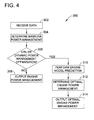
- FIG. 4 is an exemplary flow chart 300 for use with power management system 100 shown in FIG. 2 .
- data is received 302 by component 102.
- received 302 data includes at least one of sensor data, actuator position data, and ambient flight condition data.
- system 100 can receive any data that facilitates managing power as described herein.
- a baseline engine power management is determined 304 from the received data.
- the baseline engine power management is determined 304 using baseline power management component 202, which includes predefined look-up tables.
- a determination is then made whether to use dynamic online power management. If the dynamic online power management is not used, determined 304 baseline engine power management is output 308.
- engine power management includes references and constraints and is output 308 to engine controller 110.
- engine power management includes open loop input schedules and is output 308 to actuators 108 (see note about correcting signal 126 in Figure 2 ).
- engine power management can include any combination of references, constraints, and open loop input schedules that can be output to any component within an engine that facilitates managing power as described herein.
- a closed-loop engine model prediction is performed 310 by MPC 204, using determined 304 baseline engine power management and received 302 data.
- the closed-loop engine model predicts an operating condition of engine 10 using determined 304 baseline engine power management and received 302 data for a predetermined time in the future.
- MPC 204 performs the model prediction 310 for 5 seconds in the future.
- MPC 204 can perform model prediction 310 for any future time increment, including, but not limited to, 1 second, 10 seconds, 30 seconds, and 60 seconds.
- an optimal engine power management is determined 312.
- the optimal engine power management is determined 312 using an objective function.
- the objective functions used in determining 312 an optimal engine power management include, but are not limited to, a maximum thrust performance (FGT) or total thrust, a minimum turbine temperature, or a minimum specific fuel consumption (SFC).
- system 100 can switch between different objectives online as desired by the user. The switching between different objectives allows dynamic power management using MPC as opposed to conventional off-line baseline power management that is manually designed offline and cannot be changed online.
- the determined 312 optimal engine power management is obtained through optimization of the above-mentioned objective functions subject to constraints that include, but are not limited to, engine safety and operability output limits, magnitude limits, and rate limits on MPC 204 modifications.
- determined 312 optimal engine power management is output 314.
- optimal engine power management includes references and constraints that are output 314 to engine controller 110.
- optimal engine power management includes open loop input schedules that are output 314 to actuators 108.
- optimal engine power management can include any combination of references, constraints, and open loop input schedules and optimal engine power management can be output to any component within an engine that facilitates managing power as described herein.
- the above-described embodiments provide a dynamic online power management system for an engine. More specifically, the dynamic online power management systems described herein may be implemented in an aircraft to optimize an operating parameter, such as thrust, for controlling the gas turbine engine. Further, the power management systems described herein provide a bandwidth separation design. As such, it is possible to achieve low bandwidth power management that does not interfere with the fast bandwidth engine controls in an aircraft engine or similar dynamic physical system performance optimization space.
- Exemplary embodiments of methods and systems for managing power of an engine are described above in detail.
- the methods and systems are not limited to the specific embodiments described herein, but rather, components of systems and/or steps of the methods may be used independently and separately from other components and/or steps described herein.
- the methods may also be used in combination with other power management systems and methods, and are not limited to practice with only the gas turbine engine systems and methods as described herein. Rather, the exemplary embodiment can be implemented and used in connection with many other power management applications.
Landscapes
- Engineering & Computer Science (AREA)
- Chemical & Material Sciences (AREA)
- Combustion & Propulsion (AREA)
- Mechanical Engineering (AREA)
- General Engineering & Computer Science (AREA)
- Feedback Control In General (AREA)
- Supply And Distribution Of Alternating Current (AREA)
Abstract
Description
- The field of the disclosure relates generally to turbine engines and, more particularly, to methods and systems for dynamic on-line power management of an engine. In at least some known aircraft engines, the power management system is configured offline. In an offline configuration, individual optimization of control reference schedules for the controlled outputs (e.g., total thrust, fan speed), the open-loop schedules for inputs (e.g., some variable geometry), and constraint limits (e.g. fuel-air ratio, rotor speed rate of change, etc.) are determined. The reference schedules are then utilized by the engine during operation and are not updated again until the next offline configuration.
- Given the increased complexity and multivariable interaction between the inputs and outputs of current engines, offline configuration of the power management system unnecessarily limits the overall performance capability of the engine despite the advanced engine control techniques used. The design of optimum power management becomes even more challenging given that some engines, especially aircraft engines, will most frequently be operating under transient conditions due to the close integration between the flight and engine controls wherein the flight controls will be continuously modulating certain critical engine control variables.
- In one embodiment, a method for online power management of a turbine engine is provided. The method includes operating an engine control system on a first bandwidth, filtering at least one data input from the engine control system to a second bandwidth, and receiving, by a power management system operating on the second bandwidth, the at least one filtered data input. The method also includes predicting an engine operating condition using the at least one filtered data input, determining an optimal engine control based on the prediction, solving a constrained optimization for a desired optimization objective, and outputting the optimal engine control to the engine control system.
- In another embodiment, a power management system is provided. The power management system includes a baseline power management component configured to receive at least one data input and a model predictive control. The model predictive control is configured to predict an engine operating condition using the at least one data input, determine an optimal engine control based on the prediction, solve a constrained optimization for a desired optimization objective, and output the optimal engine control.
- In another embodiment, a gas turbine engine for use in an aircraft is provided. The gas turbine engine includes at least one sensor configured to sense an engine parameter and to generate a sensor input representing the engine parameter, a control system configured to control at least one of said gas turbine engine and the aircraft, and a power management system for dynamically managing the operation of an engine. The power management system includes a baseline power management component configured to receive at least one data input and a model predictive control. The model predictive control is configured to predict an engine operating condition using the at least one data input, determine an optimal engine control based on the prediction, solve a constrained optimization for a desired optimization objective, and output the optimal engine control.
-
-
FIG. 1 is a schematic view of an exemplary variable cycle gas turbine engine. -
FIG. 2 is a schematic illustration of an exemplary power management system that may be used with the gas turbine engine shown inFIG. 1 . -
FIG. 3 is a schematic illustration of an exemplary implementation of the power management system shown inFIG. 2 , employing a modification to an existing baseline power management scheme. -
FIG. 4 is an exemplary flow chart for use with the power management system shown inFIG. 2 . - The embodiments described herein provide a model within a control system, such as a Full Authority Digital Engine Control (FADEC) and/or an on-board computer. The model is used to manage power in a control system during operation using measured parameters. The embodiments described herein can be implemented within a system and are flexible enough to satisfy stringent control specifications for different operating modes of the system. For example, the embodiments described herein may be implemented in an aircraft having a wing-borne mode and jet-borne mode, wherein the embodiments described herein are adaptable to the requirements for operating in jet-borne, or hover, mode.
- The following detailed description illustrates embodiments by way of example and not by way of limitation. As used herein, an element or step recited in the singular and proceeded with the word "a" or "an" should be understood as not excluding plural elements or steps, unless such exclusion is explicitly recited. Furthermore, references to "one embodiment" of the present disclosure are not intended to be interpreted as excluding the existence of additional embodiments that also incorporate the recited features.
-
FIG. 1 is a schematic illustration of an exemplary variable-cyclegas turbine engine 10 having alongitudinal centerline 12.Gas turbine engine 10 is shown as being used with anaircraft 14. However, it should be understood thatgas turbine engine 10 can be used in any suitable commercial, industrial, and/or residential system and/or application.Gas turbine engine 10 includes anannular inlet 16 that receivesambient air 18 that is channeled downstream to afan assembly 20.Engine 10 also includes a coregas turbine engine 22 that includes a high pressure compressor (HPC) 24, acombustor 26, a high-pressure turbine (HPT) 28, a low pressure turbine (LPT) 30 and anaugmentor 32 that are coupled in an axial-flow relationship withinlet 16. HPT 28 powers HPC 24 via a first shaft 34. LPT 30powers fan assembly 20 via asecond shaft 36.Engine 10 also includes anouter casing 38 that is spaced from aninner casing 40.Inner casing 40 includes aforward section 42 that defines abypass duct 44. In the exemplary embodiment,augmentor 32 includes adiffuser liner 46. - In the exemplary embodiment,
gas turbine engine 10 also includes avalve assembly 48 coupled withinbypass duct 44.Valve assembly 48 separatesbypass duct 44 into a radiallyinner bypass duct 50 and a radiallyouter bypass duct 52. More specifically, in the exemplary embodiment,inner bypass duct 50 andouter bypass duct 52 are aligned substantially concentrically. Accordingly, and in the exemplary embodiment,fan bypass flow 54 enteringbypass duct 44 is divided into aninner bypass flow 56 and anouter bypass flow 58 byvalve assembly 48. Moreover, in the exemplary embodiment,valve assembly 48 regulates a volume ofinner bypass flow 56 channeled throughinner bypass duct 50 and a volume ofouter bypass flow 58 that is channeled throughouter bypass duct 52. - In the exemplary embodiment, a
separation liner 60 contacts anaft portion 62 ofvalve assembly 48 and is coupled todiffuser liner 46 to facilitate channelinginner bypass flow 56 throughinner bypass duct 50. Furthermore,separation liner 60 also facilitates channelingouter bypass flow 58 throughouter bypass duct 52. Aseal 64 extends betweenvalve portion 62 andseparation liner 60 to facilitate reducing leakage ofouter bypass flow 58 intoinner bypass duct 50. - During operation, air entering
engine assembly 10 throughinlet 16 is compressed byfan assembly 20. The flow of compressed air exitingfan assembly 20 is split into a first airflow portion 66 that is channeled intocore turbine engine 22 and a second airflow portion, orbypass air 68, which is channeled throughbypass duct 44. First airflow portion 66 is compressed by HPC 24 and is channeled tocombustor 26. Airflow discharged fromcombustor 26 rotatesturbines engine 10 through anexhaust 70. Further,bypass air 68 channeled byvalve assembly 48 is discharged fromengine 10 throughexhaust 70. - In the exemplary embodiment,
gas turbine engine 10 is a military turbine engine, such as an F110 engine, that is available from General Electric Company, Cincinnati, Ohio. Alternatively,gas turbine engine 10 is a commercial turbine engine, such as a CFM56 gas turbine engine and/or a CF34-10 gas turbine engine, and/or a marine/industrial engine, such as an LM6000 engine, all of which are also available from the General Electric Company. Furthermore, it should be appreciated that in other embodiments,gas turbine engine 10 may be any gas turbine engine containing similar components, such as an F136 engine available from the General Electric Company. -
FIG. 2 is a schematic illustration of an exemplarypower management system 100 that may be used withgas turbine engine 10. In the exemplary embodiment,power management system 100 includes apower management component 102 that is in communication with a closed-loopengine control system 104.Control system 104 includesengine 10, a plurality ofsensors 106, a plurality ofactuators 108, and anengine control 110. -
Sensors 106 monitor engine and/or aircraft operation and input real-time actual sensor data orsensor input 112 during engine operation to a power management model, such as acomponent 102.Exemplary sensors 106 include, but are not limited to, a faninlet temperature sensor 72, a compressor inlet total pressure sensor 74, a fan dischargestatic pressure sensor 76, a compressor dischargestatic pressure sensor 78, an exhaust ductstatic pressure sensor 80, an exhaust linerstatic pressure sensor 82, aflame detector 84, an exhaustgas temperature sensor 86, a compressor discharge temperature sensor 88, a compressorinlet temperature sensor 90, afan speed sensor 92, and a core speed sensor 94. In the exemplary embodiment,sensors 102 monitor engine rotor speeds, engine temperatures, engine pressures, fluid flows, and/or torques. - In the exemplary embodiment,
actuator position data 118 is input tocomponent 102.Actuator position data 118 includes, but is not limited to, a fuel flow actuator, variable area actuators, variable stator actuators, and/or bleed valve positions. In the exemplary embodiment, ambientflight condition data 120 is input tocomponent 102. Ambientflight condition data 120 includes, but is not limited to, ambient temperature, ambient pressure, aircraft mach number, and/or engine power setting parameters, such as fan speed or engine pressure ratio. In an alternative embodiment, any suitable data is input topower management system 100. In one embodiment, alow pass filter 114 is placed betweensensors 106 andcomponent 102 and betweenactuators 108 andcomponent 102 such that only low pass frequencies insensor data 112 andactuator position data 118 are received bycomponent 102. - In the exemplary embodiment,
control system 110 is implemented in a FADEC. Alternatively,control system 110 can be implemented in an on-board computer and/or any other system that is suitable for controllingengine 10 and/oraircraft 14. More specifically, in the exemplary embodiment,control system 110 controls operations ofengine 10, such as fuel injection, positioning of nozzle, variable bypass, and/or lift fan areas, inner and outer blocker doors in systems with multiple bypass streams, variable stators, and/or valve positions. Further, in the exemplary embodiment, references 122 andconstraints 124 are used bycontrol system 110 to control at least one engine operation.Control system 110 also receivessensor inputs 112 to control at least one operation ofengine 10. - In operation,
component 102 receivesdata data component 102outputs references 122 andconstraints 124 to controlsystem 110 andcontrol inputs 126 directly to theactuators 108 withinaircraft 14 based on the engine performance prediction. - In the exemplary embodiment, all components within
control system 104 run on an inner loop bandwidth also known as a fast inner loop. In the exemplary embodiment, inner loop bandwidth provides near real-time updates of the dynamics ofengine 10,control 110,sensors 106, andactuators 108.Component 102 and ambientflight condition data 120 run on an outer loop bandwidth that is also known as a slow outer loop. In the exemplary embodiment, receiveddata low pass filter 114.Low pass filter 114 receivessensor data 112 andactuator position data 108 near instantaneously and averages out the fast variation of the data. In the exemplary embodiment,filter 114 provides an approximation ofdata component 102 of 1 second. Alternatively, filter 114 can provide any time approximation ofdata -
FIG. 3 is a schematic illustration of anexemplary implementation 200 of thepower management system 100 shown inFIG. 2 . In the exemplary embodiment, theimplementation 200 illustrates the details of thecomponent 102 ofFIG. 2 . -
Implementation 200 includes a baselinepower management component 202 and a model predictive control (MPC) 204. In the exemplary embodiment,baseline component 202 receivessensor data 112,actuator position data 118, and ambientflight condition data 120. Baselinepower management component 202 includes tables preloaded into the component that provide references and constraint limits that are preconfigured during an offline configuration.Received data preferred control 210 that will be received byengine control 110. In the exemplary embodiment,MPC 204 reviews preferredcontrol 210 and producesoptimal modifications 212 topreferred control 210.Optimal modifications 212 can includereferences 214, open-loop inputs 216, and constraint limits 218. - The optimization occurs by the following manner:


where O is the optimization objective forMPC 204, which computes the optimized variables Δ MPC 212 and Δ̇ mpc denotes their rate of change. Y represents the controlled outputs and Yref_filt are filtered references for controlled outputs from baselinepower management component 202. In the exemplary embodiment, references are filtered to achieve a desired bandwidth that matches the outer loop bandwidth. Yopt is an optimization output and Lopt is a linear weight for the optimization output. Q is a diagonal matrix with weights on tracking error for each control output and R is a diagonal matrix with weights on rate of change of MPC action. - In the exemplary embodiment, the use of equations (1) and (2) ensure offset-less tracking of critical controlled outputs to original design values. Equation (3) achieves max feasible improvement in desired performance objective, e.g. enhanced thrust performance (FGT), or a reduction in turbine temperature, or reduced specific fuel consumption (SFC) subject to limiting constraints. In one embodiment, a quadratic cost is used in this manner with a specified target provided for the optimization output.
- In an alternative embodiment, a frequency weighted function is used to determine the
optimal modifications 212. In such an embodiment, the following is used:

- Similar to (1), (2), and (3), O is the optimization objective for
MPC 204, which computes the optimized variables Δ MPC 212 and Δ̇ mpc denotes their rate of change. Variable Y represents the controlled outputs and Yref_filt are filtered references for controlled outputs from baselinepower management component 202. In the exemplary embodiment, references are filtered to achieve a desired bandwidth that matches the outer loop bandwidth. Variable Yopt is an optimization output and Lopt is a linear weight for the optimization output. Parameter Q is a diagonal matrix with weights on tracking error for each control output, and R is a diagonal matrix with weights on rate of change ofMPC 204 action. In such an FY (z),F Δmpc (z),FYopt (z) embodiment, are frequency-weighting functions meant to operate on the discrete time functions. The solution to the problem in equation (4-6) is recast as an un-weighted Linear Quadratic control problem on the linear system with:


- The constraints on the unfiltered variables, constraint outputs Yk , and
MPC 204 changes Δ mpc are translated into equivalent constraints on the filtered variables Yk andΔ̇ mpc. - The use of (4), (5), and (6) enables
systems low pass filter 114. The frequency-weighting functions enable dynamic online power management at the desired lower bandwidth without interfering with the high-bandwidth performance of the closed-loop control system 104. -
FIG. 4 is anexemplary flow chart 300 for use withpower management system 100 shown inFIG. 2 . In the exemplary embodiment, data is received 302 bycomponent 102. In one embodiment, received 302 data includes at least one of sensor data, actuator position data, and ambient flight condition data. Alternatively,system 100 can receive any data that facilitates managing power as described herein. In the exemplary embodiment, a baseline engine power management is determined 304 from the received data. The baseline engine power management is determined 304 using baselinepower management component 202, which includes predefined look-up tables. A determination is then made whether to use dynamic online power management. If the dynamic online power management is not used, determined 304 baseline engine power management isoutput 308. In one embodiment, engine power management includes references and constraints and isoutput 308 toengine controller 110. In an alternative embodiment, engine power management includes open loop input schedules and isoutput 308 to actuators 108 (see note about correctingsignal 126 inFigure 2 ). Alternatively, engine power management can include any combination of references, constraints, and open loop input schedules that can be output to any component within an engine that facilitates managing power as described herein. - If dynamic online power management is used, a closed-loop engine model prediction is performed 310 by
MPC 204, using determined 304 baseline engine power management and received 302 data. In the exemplary embodiment, the closed-loop engine model predicts an operating condition ofengine 10 using determined 304 baseline engine power management and received 302 data for a predetermined time in the future. In one embodiment,MPC 204 performs themodel prediction 310 for 5 seconds in the future. Alternatively,MPC 204 can performmodel prediction 310 for any future time increment, including, but not limited to, 1 second, 10 seconds, 30 seconds, and 60 seconds. - Using the performed 310 model prediction, an optimal engine power management is determined 312. In one embodiment, the optimal engine power management is determined 312 using an objective function. The objective functions used in determining 312 an optimal engine power management include, but are not limited to, a maximum thrust performance (FGT) or total thrust, a minimum turbine temperature, or a minimum specific fuel consumption (SFC). In one embodiment,
system 100 can switch between different objectives online as desired by the user. The switching between different objectives allows dynamic power management using MPC as opposed to conventional off-line baseline power management that is manually designed offline and cannot be changed online. In the exemplary embodiment, the determined 312 optimal engine power management is obtained through optimization of the above-mentioned objective functions subject to constraints that include, but are not limited to, engine safety and operability output limits, magnitude limits, and rate limits onMPC 204 modifications. - In the exemplary embodiment, determined 312 optimal engine power management is
output 314. In one embodiment, optimal engine power management includes references and constraints that areoutput 314 toengine controller 110. In an alternative embodiment, optimal engine power management includes open loop input schedules that areoutput 314 toactuators 108. Alternatively, optimal engine power management can include any combination of references, constraints, and open loop input schedules and optimal engine power management can be output to any component within an engine that facilitates managing power as described herein. - The above-described embodiments provide a dynamic online power management system for an engine. More specifically, the dynamic online power management systems described herein may be implemented in an aircraft to optimize an operating parameter, such as thrust, for controlling the gas turbine engine. Further, the power management systems described herein provide a bandwidth separation design. As such, it is possible to achieve low bandwidth power management that does not interfere with the fast bandwidth engine controls in an aircraft engine or similar dynamic physical system performance optimization space.
- Exemplary embodiments of methods and systems for managing power of an engine are described above in detail. The methods and systems are not limited to the specific embodiments described herein, but rather, components of systems and/or steps of the methods may be used independently and separately from other components and/or steps described herein. For example, the methods may also be used in combination with other power management systems and methods, and are not limited to practice with only the gas turbine engine systems and methods as described herein. Rather, the exemplary embodiment can be implemented and used in connection with many other power management applications.
- Although specific features of various embodiments of the disclosure may be shown in some drawings and not in others, this is for convenience only. In accordance with the principles of the disclosure, any feature of a drawing may be referenced and/or claimed in combination with any feature of any other drawing.
- This written description uses examples for disclosure, including the best mode, and also to enable any person skilled in the art to practice the disclosure, including making and using any devices or systems and performing any incorporated methods. The patentable scope of the disclosure is defined by the claims, and may include other examples that occur to those skilled in the art. Such other examples are intended to be within the scope of the claims if they have structural elements that do not differ from the literal language of the claims, or if they include equivalent structural elements with insubstantial differences from the literal languages of the claims.
- Varied aspects and embodiments of the invention are indicated in the following clauses:
- 1. A method for online power management of a turbine engine, said method comprising:
- operating an engine control system on a first bandwidth;
- filtering at least one data input from the engine control system to a second bandwidth;
- receiving, by a power management system operating on the second bandwidth, the at least one filtered data input;
- predicting an engine operating condition over a desired future horizon using the at least one filtered data input and a closed-loop dynamic engine model;
- determining an optimal engine power management based on the prediction;
- solving a constrained optimization for a desired optimization objective; and
- outputting the optimal engine power management to the engine control system.
- 2. The method in accordance with clause 1, wherein filtering at least a data input further comprises filtering at least one of a sensor input, an actuator position input, and an ambient condition input.
- 3. The method in accordance with clause 1, further comprising determining a baseline engine power management using the at least one filtered data input.
- 4. The method in accordance with clause 3, wherein predicting an engine operating condition further comprises predicting an engine operating condition using the determined baseline engine power management.
- 5. The method in accordance with clause 1, wherein outputting the optimal engine power management further comprises outputting at least one of references, open-loop inputs, and constraint limits
- 6. The method in accordance with clause 1, wherein filtering further comprises approximating the at least one data input.
- 7. The method in accordance with clause 6, wherein approximating further comprises approximating the at least one data input for a predetermined period of time.
- 8. A power management system for online power management of an engine, said power management system comprising:
- a baseline power management component configured to receive at least one data input from an engine control system operating on a first bandwidth, wherein said baseline power management component is configured to operate on a second bandwidth; and
- a model predictive control configured to:
- predict an engine operating condition over a desired future horizon using the at least one data input and a closed-loop model of the engine;
- determine an optimal engine power management based on the prediction;
- solve a constrained optimization for a desired optimization objective; and
- output the optimal engine power management.
- 9. The power management system in accordance with clause 8, wherein said baseline power management component is further configured to determine a baseline engine power management using the at least one data input.
- 10. The power management system in accordance with clause 8, wherein the at least one data input comprises at least one of a sensor input, an actuator position input, and an ambient condition input.
- 11. The power management system in accordance with clause 8, wherein said model predictive control is further configured to predict an engine operating condition over a future horizon using the determined baseline engine power management and a closed-loop engine model.
- 12. A power management system in accordance with clause 8, wherein the optimal engine power management further comprises at least one of references, open-loop inputs, and constraint limits.
- 13. The power management system in accordance with clause 8, wherein said baseline power management component is further configured to receive at least one data input filtered by a low pass filter.
- 14. A gas turbine engine for use in an aircraft, said gas turbine engine comprising:
- at least one sensor configured to sense an engine parameter and to generate a sensor input representing the engine parameter;
- a control system configured to control at least one of said gas turbine engine; and
- a power management system for online power management of an engine, said power management system comprising:
- a baseline power management component configured to receive at least one data input; and
- a model predictive control configured to:
- predict an engine operating condition over a future horizon using the at least one data input and a closed-loop engine model;
- determine an optimal engine control based on the prediction;
- solve a constrained optimization for a desired optimization objective; and
- output the optimal engine power management.
- 15. The gas turbine engine in accordance with
clause 14, wherein said control system is configured to control one of said gas turbine engine using the optimal engine power management. - 16. The gas turbine engine in accordance with
clause 14, wherein said at least one sensor is at least one of a temperature sensor, a pressure sensor, a speed sensor, a torque sensor, a flow sensor, an ambient condition sensor, and an actuator position sensor. - 17. The gas turbine engine in accordance with
clause 14, wherein said at least one sensor and said control system operate in a closed-loop engine control system configured to operate on a first bandwidth. - 18. The gas turbine engine in accordance with clause 17, wherein said power management system operates on a second bandwidth.
- 19. The gas turbine engine in accordance with
clause 18, further comprising at least one low pass filter configured to approximate sensor input from a first bandwidth to the second bandwidth. - 20. The gas turbine engine in accordance with
clause 14, wherein the optimal engine power management further comprises at least one of references, open-loop inputs, and constraint limits.
Claims (15)
- A power management system (100, 200) for online power management of an engine (10), said power management system comprising:a baseline power management component (202) configured to receive at least one data input (112, 118, 120) from an engine control system (104) operating on a first bandwidth, wherein said baseline power management component is configured to operate on a second bandwidth; anda model predictive control (204) configured to:predict an engine operating condition over a desired future horizon using the at least one data input (112, 118, 120) and a closed-loop model of the engine;determine an optimal engine power management based on the prediction;solve a constrained optimization for a desired optimization objective; andoutput the optimal engine power management.
- The power management system (100, 200) in accordance with Claim 1, wherein said baseline power management component (202) is further configured to determine a baseline engine power management using the at least one data input (112, 118).
- The power management system (100, 200) in accordance with either of Claim 1 or 2, wherein the at least one data input (112, 118, 120) comprises at least one of a sensor input (112), an actuator position input (118), and an ambient condition input (120).
- The power management system (100, 200) in accordance with any preceding Claim, wherein said model predictive control (204) is further configured to predict an engine operating condition over a future horizon using the determined baseline engine power management and a closed-loop engine model.
- A power management system (100, 200) in accordance with any preceding Claim, wherein the optimal engine power management further comprises at least one of references (214), open-loop inputs (216), and constraint limits (218).
- The power management system (100, 200) in accordance with any preceding Claim, wherein said baseline power management component (202) is further configured to receive at least one data input (112, 118) filtered by a low pass filter (114).
- A gas turbine engine (10) for use in an aircraft (14), said gas turbine engine comprising:at least one sensor (106) configured to sense an engine parameter and to generate a sensor input (112) representing the engine parameter;a control system (104) configured to control at least one of said gas turbine engine; anda power management system (100) for online power management of the engine (10), said power management system comprising:a baseline power management component (202) configured to receive at least one data input (112, 118, 120); anda model predictive control (204) configured to:predict an engine operating condition over a future horizon using the at least one data input (112, 118, 120) and a closed-loop engine model;determine an optimal engine control based on the prediction;solve a constrained optimization for a desired optimization objective; andoutput the optimal engine power management.
- The gas turbine engine (10) in accordance with Claim 7, wherein said control system (104) is configured to control one of said gas turbine engine using the optimal engine power management.
- The gas turbine engine (10) in accordance with either of Claims 7 or 8, wherein said at least one sensor (106) is at least one of a temperature sensor, a pressure sensor, a speed sensor, a torque sensor, a flow sensor, an ambient condition sensor, and an actuator position sensor.
- The gas turbine engine (10) in accordance with any of Claims 7 to 9, wherein said at least one sensor (106) and said control system operate in a closed-loop engine control system configured to operate on a first bandwidth.
- A method (300) for online power management of a turbine engine (10), said method comprising:operating an engine control system (104) on a first bandwidth;filtering at least one data input (112, 118, 120) from the engine control system to a second bandwidth;receiving, by a power management system (100, 200) operating on the second bandwidth, the at least one filtered data input;predicting (310) an engine operating condition over a desired future horizon using the at least one filtered data input and a closed-loop dynamic engine model;determining (312) an optimal engine power management based on the prediction;solving (312) a constrained optimization for a desired optimization objective; andoutputting (314) the optimal engine power management to the engine control system.
- The method (300) in accordance with Claim 11, wherein filtering at least a data input further comprises filtering at least one of a sensor input (112), an actuator position input (118) , and an ambient condition input (120).
- The method (300) in accordance with either of Claim 11 or 12, further comprising determining (304) a baseline engine power management using the at least one filtered data input (112, 118, 120).
- The method (300) in accordance with Claim 13, wherein predicting (310) an engine operating condition further comprises predicting an engine operating condition using the determined baseline engine power management.
- The method (300) in accordance with any of Claims 11 to 14, wherein outputting (314) the optimal engine power management further comprises outputting at least one of references (214), open-loop inputs (216), and constraint limits (218).
Applications Claiming Priority (1)
| Application Number | Priority Date | Filing Date | Title |
|---|---|---|---|
| US13/352,729 US9002615B2 (en) | 2012-01-18 | 2012-01-18 | Methods and systems for managing power of an engine |
Publications (2)
| Publication Number | Publication Date |
|---|---|
| EP2617967A2 true EP2617967A2 (en) | 2013-07-24 |
| EP2617967A3 EP2617967A3 (en) | 2017-11-29 |
Family
ID=47520861
Family Applications (1)
| Application Number | Title | Priority Date | Filing Date |
|---|---|---|---|
| EP13151512.4A Withdrawn EP2617967A3 (en) | 2012-01-18 | 2013-01-16 | Methods and systems for managing power of an engine |
Country Status (6)
| Country | Link |
|---|---|
| US (1) | US9002615B2 (en) |
| EP (1) | EP2617967A3 (en) |
| JP (1) | JP2013149248A (en) |
| CN (1) | CN103216338B (en) |
| BR (1) | BR102013001227A2 (en) |
| CA (1) | CA2801592A1 (en) |
Cited By (1)
| Publication number | Priority date | Publication date | Assignee | Title |
|---|---|---|---|---|
| EP2913501A1 (en) * | 2014-02-26 | 2015-09-02 | General Electric Company | A model-based feed forward approach to coordinated air-fuel control on a gas turbine |
Families Citing this family (35)
| Publication number | Priority date | Publication date | Assignee | Title |
|---|---|---|---|---|
| US9534547B2 (en) | 2012-09-13 | 2017-01-03 | GM Global Technology Operations LLC | Airflow control systems and methods |
| US9765703B2 (en) | 2013-04-23 | 2017-09-19 | GM Global Technology Operations LLC | Airflow control systems and methods using model predictive control |
| US9435274B2 (en) | 2014-03-26 | 2016-09-06 | GM Global Technology Operations LLC | System and method for managing the period of a control loop for controlling an engine using model predictive control |
| US9732688B2 (en) | 2014-03-26 | 2017-08-15 | GM Global Technology Operations LLC | System and method for increasing the temperature of a catalyst when an engine is started using model predictive control |
| US9528453B2 (en) | 2014-11-07 | 2016-12-27 | GM Global Technologies Operations LLC | Throttle control systems and methods based on pressure ratio |
| US9714616B2 (en) | 2014-03-26 | 2017-07-25 | GM Global Technology Operations LLC | Non-model predictive control to model predictive control transitions |
| US9541019B2 (en) | 2014-03-26 | 2017-01-10 | GM Global Technology Operations LLC | Estimation systems and methods with model predictive control |
| US9388758B2 (en) * | 2014-03-26 | 2016-07-12 | GM Global Technology Operations LLC | Model predictive control systems and methods for future torque changes |
| US9599053B2 (en) | 2014-03-26 | 2017-03-21 | GM Global Technology Operations LLC | Model predictive control systems and methods for internal combustion engines |
| US9797318B2 (en) | 2013-08-02 | 2017-10-24 | GM Global Technology Operations LLC | Calibration systems and methods for model predictive controllers |
| US9920697B2 (en) | 2014-03-26 | 2018-03-20 | GM Global Technology Operations LLC | Engine control systems and methods for future torque request increases |
| US9587573B2 (en) | 2014-03-26 | 2017-03-07 | GM Global Technology Operations LLC | Catalyst light off transitions in a gasoline engine using model predictive control |
| US9429085B2 (en) | 2013-04-23 | 2016-08-30 | GM Global Technology Operations LLC | Airflow control systems and methods using model predictive control |
| US9605615B2 (en) | 2015-02-12 | 2017-03-28 | GM Global Technology Operations LLC | Model Predictive control systems and methods for increasing computational efficiency |
| US9599049B2 (en) | 2014-06-19 | 2017-03-21 | GM Global Technology Operations LLC | Engine speed control systems and methods |
| US9399959B2 (en) | 2014-03-26 | 2016-07-26 | GM Global Technology Operations LLC | System and method for adjusting a torque capacity of an engine using model predictive control |
| US9784198B2 (en) | 2015-02-12 | 2017-10-10 | GM Global Technology Operations LLC | Model predictive control systems and methods for increasing computational efficiency |
| US9863345B2 (en) | 2012-11-27 | 2018-01-09 | GM Global Technology Operations LLC | System and method for adjusting weighting values assigned to errors in target actuator values of an engine when controlling the engine using model predictive control |
| US9322341B2 (en) * | 2013-03-12 | 2016-04-26 | Pratt & Whitney Canada Corp. | System and method for engine transient power response |
| US9260105B2 (en) * | 2013-08-05 | 2016-02-16 | GM Global Technology Operations LLC | System and method of power management for a hybrid vehicle |
| EP2853719A1 (en) * | 2013-09-25 | 2015-04-01 | Alstom Technology Ltd | Gas turbine with staged fuel injection |
| US9885609B2 (en) * | 2014-05-23 | 2018-02-06 | United Technologies Corporation | Gas turbine engine optical system |
| CN104407607A (en) * | 2014-10-15 | 2015-03-11 | 天津全华时代航天科技发展有限公司 | Unmanned aerial vehicle first-person perspective control system |
| CN104848975A (en) * | 2015-05-21 | 2015-08-19 | 遵义天义利威机电有限责任公司 | Power detection apparatus of motor |
| US20170138781A1 (en) * | 2015-11-17 | 2017-05-18 | General Electric Company | Method and system for improving parameter measurement |
| US10235818B2 (en) * | 2016-05-13 | 2019-03-19 | Ford Global Technologies, Llc | Adaptive vehicle control |
| US9938908B2 (en) | 2016-06-14 | 2018-04-10 | GM Global Technology Operations LLC | System and method for predicting a pedal position based on driver behavior and controlling one or more engine actuators based on the predicted pedal position |
| US10190522B2 (en) | 2016-06-17 | 2019-01-29 | Toyota Motor Engineering & Manufacturing North America, Inc. | Hybrid partial and full step quadratic solver for model predictive control of diesel engine air path flow and methods of use |
| US10604268B2 (en) * | 2017-02-22 | 2020-03-31 | Pratt & Whitney Canada Corp. | Autothrottle control for turboprop engines |
| US10655494B2 (en) * | 2018-10-17 | 2020-05-19 | United Technologies Corporation | Model predictive control sub-system power management |
| WO2020093264A1 (en) * | 2018-11-07 | 2020-05-14 | 大连理工大学 | Design method for optimizing aero-engine transition state control law |
| US10815904B2 (en) | 2019-03-06 | 2020-10-27 | General Electric Company | Prognostic health management control for adaptive operability recovery for turbine engines |
| JP7348126B2 (en) | 2020-03-30 | 2023-09-20 | 三菱重工業株式会社 | Control device, control input determination method, and control input determination program |
| US11936184B2 (en) | 2021-08-19 | 2024-03-19 | Caterpillar Inc. | Systems and methods for operating hybrid power system by combining prospective and real-time optimizations |
| US11962156B2 (en) | 2021-08-19 | 2024-04-16 | Caterpillar Inc. | Systems and methods for constrained optimization of a hybrid power system that accounts for asset maintenance and degradation |
Family Cites Families (28)
| Publication number | Priority date | Publication date | Assignee | Title |
|---|---|---|---|---|
| US5080496A (en) * | 1990-06-25 | 1992-01-14 | General Electric Company | Method and apparatus for compensated temperature prediction |
| EP0903469B1 (en) * | 1997-09-22 | 2002-10-30 | Alstom | Method for controlling the power of a turbine plant and device for implementing the method |
| US6163681A (en) * | 1999-06-25 | 2000-12-19 | Harris Corporation | Wireless spread spectrum ground link-based aircraft data communication system with variable data rate |
| US6715916B2 (en) * | 2001-02-08 | 2004-04-06 | General Electric Company | System and method for determining gas turbine firing and combustion reference temperatures having correction for water content in fuel |
| JP4056232B2 (en) * | 2001-08-23 | 2008-03-05 | 三菱重工業株式会社 | Gas turbine control device, gas turbine system, and gas turbine remote monitoring system |
| US6729139B2 (en) * | 2001-09-26 | 2004-05-04 | Goodrich Pump & Engine Control Systems, Inc. | Engine control system |
| JP2003113721A (en) * | 2001-10-03 | 2003-04-18 | Mitsubishi Heavy Ind Ltd | Method and apparatus for adjusting fuel ratio in gas turbine combustor |
| US7210653B2 (en) | 2002-10-22 | 2007-05-01 | The Boeing Company | Electric-based secondary power system architectures for aircraft |
| US6823675B2 (en) * | 2002-11-13 | 2004-11-30 | General Electric Company | Adaptive model-based control systems and methods for controlling a gas turbine |
| JP4555562B2 (en) * | 2003-12-09 | 2010-10-06 | ゼネラル・エレクトリック・カンパニイ | Method and apparatus for model predictive control of aircraft gas turbines |
| JP4326317B2 (en) * | 2003-12-11 | 2009-09-02 | 三菱重工業株式会社 | Gas turbine control device |
| US20050193739A1 (en) * | 2004-03-02 | 2005-09-08 | General Electric Company | Model-based control systems and methods for gas turbine engines |
| US7031812B1 (en) | 2004-03-15 | 2006-04-18 | Howell Instruments, Inc. | System and method for monitoring aircraft engine health and determining engine power available, and applications thereof |
| EP1724528A1 (en) * | 2005-05-13 | 2006-11-22 | Siemens Aktiengesellschaft | Method and apparatus for regulating the functioning of a gas turbine combustor |
| US7632012B2 (en) * | 2005-09-01 | 2009-12-15 | Siemens Energy, Inc. | Method of measuring in situ differential emissivity and temperature |
| US7866159B2 (en) * | 2005-10-18 | 2011-01-11 | Rolls-Royce Corporation | Variable geometry hysteresis control for a gas turbine engine |
| US7603222B2 (en) * | 2005-11-18 | 2009-10-13 | General Electric Company | Sensor diagnostics using embedded model quality parameters |
| US7857107B2 (en) | 2006-11-01 | 2010-12-28 | The Boeing Company | Ground towing power architecture for an electric brake system of an aircraft |
| US7853392B2 (en) * | 2007-01-26 | 2010-12-14 | General Electric Company | Systems and methods for initializing dynamic model states using a Kalman filter |
| US7979255B2 (en) | 2007-03-16 | 2011-07-12 | Airbus Operations Sas | Method, system and computer program product for the optimization of power system architectures at the aircraft level during pre-design |
| US7468561B2 (en) | 2007-03-27 | 2008-12-23 | General Electric Company | Integrated electrical power extraction for aircraft engines |
| US20090090817A1 (en) | 2007-10-09 | 2009-04-09 | Monka Gary H | Aircraft configuration, gas turbine engine, controller and trim system for neutralizing pitching moments with power changes |
| US8288885B2 (en) | 2008-06-03 | 2012-10-16 | Honeywell International Inc. | Method and system for improving electrical load regeneration management of an aircraft |
| US20100170262A1 (en) | 2009-01-06 | 2010-07-08 | Kaslusky Scott F | Aircraft power and thermal management system with electric co-generation |
| US8882028B2 (en) | 2009-09-21 | 2014-11-11 | Aerion Corporation | Aircraft emergency and backup secondary power apparatus |
| US8296036B2 (en) | 2009-09-23 | 2012-10-23 | Aerovironment, Inc. | Aircraft power management |
| FR2989796B1 (en) * | 2012-04-20 | 2014-04-11 | Eurocopter France | AIRCRAFT EMERGENCY INSTRUMENT COMBINING FLIGHT INFORMATION, POWER MARGIN INFORMATION AND STEERING ASSISTANCE |
| US9099980B2 (en) * | 2013-05-06 | 2015-08-04 | Pratt & Whitney Canada Corp | Dynamically detecting resonating frequencies of resonating structures |
-
2012
- 2012-01-18 US US13/352,729 patent/US9002615B2/en active Active
-
2013
- 2013-01-10 CA CA2801592A patent/CA2801592A1/en not_active Abandoned
- 2013-01-15 JP JP2013004167A patent/JP2013149248A/en not_active Ceased
- 2013-01-16 EP EP13151512.4A patent/EP2617967A3/en not_active Withdrawn
- 2013-01-17 BR BR102013001227-0A patent/BR102013001227A2/en not_active IP Right Cessation
- 2013-01-18 CN CN201310026206.7A patent/CN103216338B/en active Active
Non-Patent Citations (1)
| Title |
|---|
| None |
Cited By (2)
| Publication number | Priority date | Publication date | Assignee | Title |
|---|---|---|---|---|
| EP2913501A1 (en) * | 2014-02-26 | 2015-09-02 | General Electric Company | A model-based feed forward approach to coordinated air-fuel control on a gas turbine |
| US9677476B2 (en) | 2014-02-26 | 2017-06-13 | General Electric Company | Model-based feed forward approach to coordinated air-fuel control on a gas turbine |
Also Published As
| Publication number | Publication date |
|---|---|
| JP2013149248A (en) | 2013-08-01 |
| US20130184961A1 (en) | 2013-07-18 |
| CN103216338B (en) | 2016-08-03 |
| BR102013001227A2 (en) | 2014-08-26 |
| US9002615B2 (en) | 2015-04-07 |
| CN103216338A (en) | 2013-07-24 |
| CA2801592A1 (en) | 2013-07-18 |
| EP2617967A3 (en) | 2017-11-29 |
Similar Documents
| Publication | Publication Date | Title |
|---|---|---|
| US9002615B2 (en) | Methods and systems for managing power of an engine | |
| EP3045982B1 (en) | System and method for controlling a gas turbine engine | |
| US11428171B2 (en) | Electric machine assistance for multi-spool turbomachine operation and control | |
| EP3147220B1 (en) | Single lever turboprop control systems and methods utilizing torque-based and power-based scheduling | |
| US10801359B2 (en) | Method and system for identifying rub events | |
| US10794286B2 (en) | Method and system for modulated turbine cooling as a function of engine health | |
| RU2608802C2 (en) | System and method for auto configuration of fuel combustion system of gas turbine | |
| EP3023617B1 (en) | Gas turbine engine with adjustable flow path geometry | |
| EP2025878A2 (en) | Aircraft gas turbine engine blade tip clearance control | |
| US20170175646A1 (en) | Method and system for stall margin modulation as a function of engine health | |
| EP4116561B1 (en) | Model based fuel-air ratio control | |
| EP2813686B1 (en) | Operations support system for a gas tubine engine | |
| US10711734B2 (en) | Optimal thrust control of an aircraft engine | |
| US10378376B2 (en) | Method and system for adjusting an operating parameter as a function of component health | |
| EP3219993A1 (en) | Controlling a compressor of a gas turbine engine | |
| Csank et al. | Enhanced engine performance during emergency operation using a model-based engine control architecture | |
| EP3734047A1 (en) | Model-based rotor speed keep out zone control | |
| US20200070081A1 (en) | Monitoring servo-valve filter elements | |
| EP4245979A1 (en) | Methods and systems for controlling an engine system of a vehicle | |
| EP3546734A1 (en) | Gasturbine with a variable area fan nozzle fan flutter management system | |
| US12313012B2 (en) | System and method for reducing a clearance gap in an engine |
Legal Events
| Date | Code | Title | Description |
|---|---|---|---|
| PUAI | Public reference made under article 153(3) epc to a published international application that has entered the european phase |
Free format text: ORIGINAL CODE: 0009012 |
|
| AK | Designated contracting states |
Kind code of ref document: A2 Designated state(s): AL AT BE BG CH CY CZ DE DK EE ES FI FR GB GR HR HU IE IS IT LI LT LU LV MC MK MT NL NO PL PT RO RS SE SI SK SM TR |
|
| AX | Request for extension of the european patent |
Extension state: BA ME |
|
| PUAL | Search report despatched |
Free format text: ORIGINAL CODE: 0009013 |
|
| AK | Designated contracting states |
Kind code of ref document: A3 Designated state(s): AL AT BE BG CH CY CZ DE DK EE ES FI FR GB GR HR HU IE IS IT LI LT LU LV MC MK MT NL NO PL PT RO RS SE SI SK SM TR |
|
| AX | Request for extension of the european patent |
Extension state: BA ME |
|
| RIC1 | Information provided on ipc code assigned before grant |
Ipc: F02C 9/28 20060101AFI20171024BHEP Ipc: F02C 9/00 20060101ALI20171024BHEP |
|
| STAA | Information on the status of an ep patent application or granted ep patent |
Free format text: STATUS: THE APPLICATION IS DEEMED TO BE WITHDRAWN |
|
| 18D | Application deemed to be withdrawn |
Effective date: 20180530 |