EP2617958A1 - Engine equipped with exhaust treatment device and method for attaching said exhaust treatment device - Google Patents
Engine equipped with exhaust treatment device and method for attaching said exhaust treatment device Download PDFInfo
- Publication number
- EP2617958A1 EP2617958A1 EP11825001.8A EP11825001A EP2617958A1 EP 2617958 A1 EP2617958 A1 EP 2617958A1 EP 11825001 A EP11825001 A EP 11825001A EP 2617958 A1 EP2617958 A1 EP 2617958A1
- Authority
- EP
- European Patent Office
- Prior art keywords
- side support
- support stay
- treatment device
- exhaust treatment
- engine
- Prior art date
- Legal status (The legal status is an assumption and is not a legal conclusion. Google has not performed a legal analysis and makes no representation as to the accuracy of the status listed.)
- Granted
Links
Images



Classifications
-
- F—MECHANICAL ENGINEERING; LIGHTING; HEATING; WEAPONS; BLASTING
- F01—MACHINES OR ENGINES IN GENERAL; ENGINE PLANTS IN GENERAL; STEAM ENGINES
- F01N—GAS-FLOW SILENCERS OR EXHAUST APPARATUS FOR MACHINES OR ENGINES IN GENERAL; GAS-FLOW SILENCERS OR EXHAUST APPARATUS FOR INTERNAL-COMBUSTION ENGINES
- F01N3/00—Exhaust or silencing apparatus having means for purifying, rendering innocuous, or otherwise treating exhaust
- F01N3/08—Exhaust or silencing apparatus having means for purifying, rendering innocuous, or otherwise treating exhaust for rendering innocuous
- F01N3/10—Exhaust or silencing apparatus having means for purifying, rendering innocuous, or otherwise treating exhaust for rendering innocuous by thermal or catalytic conversion of noxious components of exhaust
- F01N3/24—Exhaust or silencing apparatus having means for purifying, rendering innocuous, or otherwise treating exhaust for rendering innocuous by thermal or catalytic conversion of noxious components of exhaust characterised by constructional aspects of converting apparatus
- F01N3/28—Construction of catalytic reactors
-
- F—MECHANICAL ENGINEERING; LIGHTING; HEATING; WEAPONS; BLASTING
- F01—MACHINES OR ENGINES IN GENERAL; ENGINE PLANTS IN GENERAL; STEAM ENGINES
- F01N—GAS-FLOW SILENCERS OR EXHAUST APPARATUS FOR MACHINES OR ENGINES IN GENERAL; GAS-FLOW SILENCERS OR EXHAUST APPARATUS FOR INTERNAL-COMBUSTION ENGINES
- F01N13/00—Exhaust or silencing apparatus characterised by constructional features
- F01N13/18—Construction facilitating manufacture, assembly, or disassembly
- F01N13/1805—Fixing exhaust manifolds, exhaust pipes or pipe sections to each other, to engine or to vehicle body
-
- B—PERFORMING OPERATIONS; TRANSPORTING
- B60—VEHICLES IN GENERAL
- B60K—ARRANGEMENT OR MOUNTING OF PROPULSION UNITS OR OF TRANSMISSIONS IN VEHICLES; ARRANGEMENT OR MOUNTING OF PLURAL DIVERSE PRIME-MOVERS IN VEHICLES; AUXILIARY DRIVES FOR VEHICLES; INSTRUMENTATION OR DASHBOARDS FOR VEHICLES; ARRANGEMENTS IN CONNECTION WITH COOLING, AIR INTAKE, GAS EXHAUST OR FUEL SUPPLY OF PROPULSION UNITS IN VEHICLES
- B60K13/00—Arrangement in connection with combustion air intake or gas exhaust of propulsion units
- B60K13/04—Arrangement in connection with combustion air intake or gas exhaust of propulsion units concerning exhaust
-
- F—MECHANICAL ENGINEERING; LIGHTING; HEATING; WEAPONS; BLASTING
- F01—MACHINES OR ENGINES IN GENERAL; ENGINE PLANTS IN GENERAL; STEAM ENGINES
- F01N—GAS-FLOW SILENCERS OR EXHAUST APPARATUS FOR MACHINES OR ENGINES IN GENERAL; GAS-FLOW SILENCERS OR EXHAUST APPARATUS FOR INTERNAL-COMBUSTION ENGINES
- F01N13/00—Exhaust or silencing apparatus characterised by constructional features
- F01N13/18—Construction facilitating manufacture, assembly, or disassembly
- F01N13/1805—Fixing exhaust manifolds, exhaust pipes or pipe sections to each other, to engine or to vehicle body
- F01N13/1811—Fixing exhaust manifolds, exhaust pipes or pipe sections to each other, to engine or to vehicle body with means permitting relative movement, e.g. compensation of thermal expansion or vibration
- F01N13/1822—Fixing exhaust manifolds, exhaust pipes or pipe sections to each other, to engine or to vehicle body with means permitting relative movement, e.g. compensation of thermal expansion or vibration for fixing exhaust pipes or devices to vehicle body
-
- F—MECHANICAL ENGINEERING; LIGHTING; HEATING; WEAPONS; BLASTING
- F01—MACHINES OR ENGINES IN GENERAL; ENGINE PLANTS IN GENERAL; STEAM ENGINES
- F01N—GAS-FLOW SILENCERS OR EXHAUST APPARATUS FOR MACHINES OR ENGINES IN GENERAL; GAS-FLOW SILENCERS OR EXHAUST APPARATUS FOR INTERNAL-COMBUSTION ENGINES
- F01N3/00—Exhaust or silencing apparatus having means for purifying, rendering innocuous, or otherwise treating exhaust
- F01N3/02—Exhaust or silencing apparatus having means for purifying, rendering innocuous, or otherwise treating exhaust for cooling, or for removing solid constituents of, exhaust
-
- F—MECHANICAL ENGINEERING; LIGHTING; HEATING; WEAPONS; BLASTING
- F01—MACHINES OR ENGINES IN GENERAL; ENGINE PLANTS IN GENERAL; STEAM ENGINES
- F01N—GAS-FLOW SILENCERS OR EXHAUST APPARATUS FOR MACHINES OR ENGINES IN GENERAL; GAS-FLOW SILENCERS OR EXHAUST APPARATUS FOR INTERNAL-COMBUSTION ENGINES
- F01N3/00—Exhaust or silencing apparatus having means for purifying, rendering innocuous, or otherwise treating exhaust
- F01N3/08—Exhaust or silencing apparatus having means for purifying, rendering innocuous, or otherwise treating exhaust for rendering innocuous
- F01N3/10—Exhaust or silencing apparatus having means for purifying, rendering innocuous, or otherwise treating exhaust for rendering innocuous by thermal or catalytic conversion of noxious components of exhaust
- F01N3/24—Exhaust or silencing apparatus having means for purifying, rendering innocuous, or otherwise treating exhaust for rendering innocuous by thermal or catalytic conversion of noxious components of exhaust characterised by constructional aspects of converting apparatus
-
- F—MECHANICAL ENGINEERING; LIGHTING; HEATING; WEAPONS; BLASTING
- F01—MACHINES OR ENGINES IN GENERAL; ENGINE PLANTS IN GENERAL; STEAM ENGINES
- F01N—GAS-FLOW SILENCERS OR EXHAUST APPARATUS FOR MACHINES OR ENGINES IN GENERAL; GAS-FLOW SILENCERS OR EXHAUST APPARATUS FOR INTERNAL-COMBUSTION ENGINES
- F01N2340/00—Dimensional characteristics of the exhaust system, e.g. length, diameter or volume of the exhaust apparatus; Spatial arrangements of exhaust apparatuses
-
- F—MECHANICAL ENGINEERING; LIGHTING; HEATING; WEAPONS; BLASTING
- F01—MACHINES OR ENGINES IN GENERAL; ENGINE PLANTS IN GENERAL; STEAM ENGINES
- F01N—GAS-FLOW SILENCERS OR EXHAUST APPARATUS FOR MACHINES OR ENGINES IN GENERAL; GAS-FLOW SILENCERS OR EXHAUST APPARATUS FOR INTERNAL-COMBUSTION ENGINES
- F01N2590/00—Exhaust or silencing apparatus adapted to particular use, e.g. for military applications, airplanes, submarines
- F01N2590/08—Exhaust or silencing apparatus adapted to particular use, e.g. for military applications, airplanes, submarines for heavy duty applications, e.g. trucks, buses, tractors, locomotives
-
- Y—GENERAL TAGGING OF NEW TECHNOLOGICAL DEVELOPMENTS; GENERAL TAGGING OF CROSS-SECTIONAL TECHNOLOGIES SPANNING OVER SEVERAL SECTIONS OF THE IPC; TECHNICAL SUBJECTS COVERED BY FORMER USPC CROSS-REFERENCE ART COLLECTIONS [XRACs] AND DIGESTS
- Y10—TECHNICAL SUBJECTS COVERED BY FORMER USPC
- Y10T—TECHNICAL SUBJECTS COVERED BY FORMER US CLASSIFICATION
- Y10T29/00—Metal working
- Y10T29/49—Method of mechanical manufacture
- Y10T29/49398—Muffler, manifold or exhaust pipe making
-
- Y—GENERAL TAGGING OF NEW TECHNOLOGICAL DEVELOPMENTS; GENERAL TAGGING OF CROSS-SECTIONAL TECHNOLOGIES SPANNING OVER SEVERAL SECTIONS OF THE IPC; TECHNICAL SUBJECTS COVERED BY FORMER USPC CROSS-REFERENCE ART COLLECTIONS [XRACs] AND DIGESTS
- Y10—TECHNICAL SUBJECTS COVERED BY FORMER USPC
- Y10T—TECHNICAL SUBJECTS COVERED BY FORMER US CLASSIFICATION
- Y10T29/00—Metal working
- Y10T29/49—Method of mechanical manufacture
- Y10T29/49764—Method of mechanical manufacture with testing or indicating
- Y10T29/49778—Method of mechanical manufacture with testing or indicating with aligning, guiding, or instruction
-
- Y—GENERAL TAGGING OF NEW TECHNOLOGICAL DEVELOPMENTS; GENERAL TAGGING OF CROSS-SECTIONAL TECHNOLOGIES SPANNING OVER SEVERAL SECTIONS OF THE IPC; TECHNICAL SUBJECTS COVERED BY FORMER USPC CROSS-REFERENCE ART COLLECTIONS [XRACs] AND DIGESTS
- Y10—TECHNICAL SUBJECTS COVERED BY FORMER USPC
- Y10T—TECHNICAL SUBJECTS COVERED BY FORMER US CLASSIFICATION
- Y10T29/00—Metal working
- Y10T29/49—Method of mechanical manufacture
- Y10T29/49764—Method of mechanical manufacture with testing or indicating
- Y10T29/49778—Method of mechanical manufacture with testing or indicating with aligning, guiding, or instruction
- Y10T29/4978—Assisting assembly or disassembly
Definitions
- the present invention relates to an engine with an exhaust treatment device and an attachment method for the exhaust treatment device, and in detail, relates to an engine with an exhaust treatment device with which an attachment task of the exhaust treatment device to an engine rear upper portion becomes simplified and an attachment method for the exhaust treatment device.
- an engine with an exhaust treatment device there is an engine with an exhaust treatment device, wherein the installing direction of a crankshaft is the front and rear direction, a flywheel is placed on the rear side, and the width direction of the engine is the lateral direction, a sideways exhaust treatment device is arranged on the rear upper side of the engine, an engine exhaust outlet flange is arranged on a one side of the engine, an exhaust inlet flange is arranged in a one-side portion of the exhaust treatment device, the exhaust inlet flange is attached to the engine exhaust outlet flange by exhaust flange fastening tools, a one-side support stay mount surface and an other-side support stay mount surface are provided in an engine rear upper portion, a front portion of a one-side support stay is mounted on the one-side support stay mount surface and attached by a one-side support stay fastening tool, and a front portion of an other-side support stay is mounted on the other-side support stay mount surface and attached by an other-side support stay fastening tool, so
- Patent Document 1 Japanese Patent Laid-open Publication No. 2010-71175 (refer to Figs. 15, 16, 18)
- both the one-side support stay and the other-side support stay are welded to the exhaust deice.
- An object of the present invention is to provide an engine with an exhaust treatment device with which an attachment task of the exhaust treatment device to an engine rear upper portion becomes simplified and an attachment method for the exhaust treatment device.
- a particular matter of the invention according to claim 1 is as follows.
- An engine with an exhaust treatment device wherein: as shown in Figs. 1 (A) and 1 (B) , the installing direction of a crankshaft is the front and rear direction, a flywheel (1) is placed on the rear side, and the width direction of the engine is the lateral direction; a sideways exhaust treatment device (2) is arranged on the rear upper side of the engine; an engine exhaust outlet flange (3) is arranged on a one side of the engine, an exhaust inlet flange (5) is arranged in a one-side portion (4) of the exhaust treatment device (2), and the exhaust inlet flange (5) is attached to the engine exhaust outlet flange (3) by exhaust flange fastening tools (6) (6) (6); and a one-side support stay mount surface (8) and an other-side support stay mount surface (9) are provided in an engine rear upper portion (7), a front portion (10a) of a one-side support stay (10) is mounted on the one-side support stay mount surface (8)
- one-side support portions (14) (14) are provided in the one-side support stay (10), and other-side support portions (15) (15) are provided in the other-side support stay (12); one-side supported portions (16) (16) and other-side supported portions (17) (17) are provided in the exhaust treatment device (2); upon attaching the one-side supported portions (16) (16) of the exhaust treatment device (2) to the one-side support portions (14) (14) of the one-side support stay (10) by one-side supported portion fastening tools (18) (18), and attaching the other-side supported portions (17) (17) of the exhaust treatment device (2) to the other-side support portions (15) (15) of the other-side support stay (12) by other-side supported portion fastening tools (19) (19);
- Fig. 1 (A) by providing a cutout groove (20) having an opening (23) in one end in the front portion (12a) of the other-side support stay (12), and inserting the other-side support stay fastening tool (13) attached to the other-side support stay mount surface (9) into the cutout groove (20); in a case where the other-side support stay fastening tool (13) is brought into the cutout groove (20) from the opening (23) while guiding the front portion (12a) of the other-side support stay (12) by the other-side support stay mount surface (9), rotation moment of the other-side support stay (12) generated by a load of an other-side portion (50) of the exhaust treatment device (2) is received by the other-side support stay fastening tool (13) via an edge portion (21) of the cutout groove (20), so that the load of the other-side portion (50) of the exhaust treatment device (2) is capable of being supported by the other-side support stay (12); and
- a particular matter of the invention according to claim 11 is as follows.
- the invention according to claim 1 exerts the following effect.
- the invention according to claim 1 as in the invention according to claim 11, as shown in Figs. 1 (A) and 1 (B) , during the attachment task of the exhaust treatment device (2) to the engine rear upper portion (7), the load of the other-side portion (50) of the exhaust treatment device (2) can be supported by the other-side support stay (12) and the load of the one-side portion (4) of the exhaust treatment device (2) can be supported by the one-side support stay (10).
- an external support device such as a crane
- a support task of the other-side portion of the exhaust treatment device is simple.
- the invention according to claim 1 as in the invention according to claim 11, as shown in Fig. 1(A) , by bringing the other-side support stay fastening tool (13) into the cutout groove (20) from the opening (23) while guiding the front portion (12a) of the other-side support stay (12) by the other-side support stay mount surface (9), the load of the other-side portion (50) of the exhaust treatment device (2) can be supported by the other-side support stay (12).
- the support task of the other-side portion (50) of the exhaust treatment device (2) is simple.
- the invention according to claim 2 exerts the following effect in addition to the effect of the invention according to claim 1.
- ⁇ Effect>> The other-side supported portion fastening tools can be prevented from being loosened by vibration of the engine.
- mating surfaces (24) (24) of the other-side support portions (15) (15) of the other-side support stay (12) can be overlapped with mating surfaces (25) (25) of the other-side supported portions (17) (17) of the exhaust treatment device (2) from the side, and the other-side supported portion fastening tools (19) (19) can be fastened while axes thereof are placed sideways.
- the other-side support portions (15) (15) and the other-side supported portions (17) (17) can be brought into a proper attachment posture where both the mating surfaces (24) (25) are closely attached, and these can be properly fastened by the other-side supported portion fastening tools (19) (19) from both the sides. Therefore, the other-side supported portion fastening tools (19) (19) can be prevented from being loosened by the vibration of the engine.
- the invention according to claim 3 exerts the following effect in addition to the effect of the invention according to claim 2.
- ⁇ Effect>> A position setting task of the rear other-side supported portion fastening tool is simple.
- the load of the one-side portion (4) of the exhaust treatment device (2) is supported by the exhaust flange fastening tool (6) positioned in the up and down direction and the lateral direction by attachment to the engine exhaust outlet flange (3)
- the load of the other-side portion (50) of the exhaust treatment device (2) is supported by the other-side support stay (12) via the front other-side supported portion fastening tool (19) whose up-down position is set at an overlapping position of a circular hole and a front-rear long hole on the front side
- the exhaust treatment device (2) is retained at a predetermined attachment posture positioned in the front and rear direction, the lateral direction, and the up and down direction.
- the rear other-side supported portion fastening tool (19) can be set at a crossing position of a front-rear long hole and an up-down long hole on the rear side.
- the position setting task of the rear other-side supported portion fastening tool (19) is simple.
- the invention according to claim 4 exerts the following effect in addition to the effect of the invention according to claim 2 or 3. ⁇ Effect>>
- the one-side supported portion fastening tools can be prevented from being loosened by the vibration of the engine.
- mating surfaces (28) (28) of the one-side support portions (14) (14) of the one-side support stay (10) can be overlapped with mating surfaces (29) (29) of the one-side supported portions (16) (16) of the exhaust treatment device (2) from the side, and the one-side supported portion fastening tools (18) (18) can be fastened while axes thereof are placed sideways.
- the one-side support portions (14) (14) and the one-side supported portions (16) (16) can be brought into a proper attachment posture where both the mating surfaces (28) (29) are closely attached, and these can be properly fastened by the one-side supported portion fastening tools (18) (18) from both the sides. Therefore, the one-side supported portion fastening tools (18) (18) can be prevented from being loosened by the vibration of the engine.
- the invention according to claim 5 exerts the following effect in addition to the effect of the invention according to claim 4.
- ⁇ Effect>> A position setting task of the pair of front and rear one-side supported portion fastening tools is simple.
- the invention according to claim 5 as in the invention according to claim 15, as shown in Fig. 1 (A) , by overlapping the mating surfaces (28) (28) of the one-side support portions (14) (14) of the one-side support stay (10) whose front-rear position is set with the mating surfaces (29) (29) of the one-side supported portions (16) (16) of the exhaust treatment device (2) retained at a predetermined attachment posture from the side, as shown in Fig.
- a crossing position of an up-down long hole and a front-rear long hole on the front side is set and a crossing position of an up-down long hole and a front-rear long hole on the rear side is set, and the pair of front and rear one-side supported portion fastening tools (18) (18) is inserted and attached to the set pair of front and rear crossing positions, so that the one-side supported portions (16) (16) can be fixed to the one-side support portions (14) (14).
- the position setting task of the pair of front and rear one-side supported portion fastening tools (18) (18) is simple.
- the invention according to claim 6 exerts the following effect in addition to the effect of the invention according to any of claims 2 to 5.
- «Effect» The exhaust treatment device is stably supported on the engine rear upper portion.
- a part of the rotation moment of the other-side support stay (12) generated by the load of the other-side portion (50) of the exhaust treatment device (2) can be received by an other-side stay pressure receiving surface (34) of an engine rear surface (32) via an other-side support stay positioning piece (36), and a part of rotation moment of the one-side support stay (10) generated by the load of the one-side portion (4) of the exhaust treatment device (2) can be received by a one-side stay pressure receiving surface (33) of the engine rear surface (32) via a one-side support stay positioning piece (35).
- the exhaust treatment device (2) is stably supported on the engine rear upper portion (7) via the other-side support stay (12) and the one-side support stay (10).
- the invention according to claim 7 exerts the following effect in addition to the effect of the invention according to any of claims 1 to 6.
- the exhaust treatment device is stably supported on the engine rear upper portion. As shown in Figs. 1(A) and 1(B) and 2(A) and 2(B) , the one-side supported portions (16) (16) and the other-side supported portions (17) (17) of the exhaust treatment device (2) are extended from predetermined coupling flanges (41) (42). Thus, the exhaust treatment device (2) is stably supported on the engine rear upper portion (7) via the coupling flanges (41) (42) formed to be highly rigid.
- the invention according to claim 8 exerts the following effect in addition to the effect of the invention according to claim 7.
- «Effect» Maintenance in a DPF and a casing of the exhaust treatment device can be easily performed.
- an exhaust inlet side casing part (37) and an exhaust outlet side casing part (39) are detachable from a DPF housing casing part (38).
- the maintenance in a DPF (51) and the casing of the exhaust treatment device (2) can be easily performed.
- the invention according to claim 9 exerts the following effect in addition to the effect of the invention according to claim 8.
- «Effect» The protruding direction of an exhaust outlet pipe applicable to a model in which the engine is mounted can be readily selected.
- Fig. 2(B) by displacing the exhaust outlet side casing part (39) in the circumferential direction by the distant angle, matching fastened portions (47) (47) (47) (47) (47) (47) (47) of a coupling flange (43) of the exhaust outlet side casing part (39) with fastened portions (46) (46) (46) (46) (46) (46) of the coupling flange (42) of the DPF housing casing part (38), and coupling the exhaust outlet side casing part (39) to the DPF housing casing part (38) by flange fastening tools (45) (45) (45) (45) (45), the protruding direction of an exhaust outlet pipe (44) from an outer peripheral surface of the exhaust outlet side casing part (39) can be selected.
- the invention according to claim 10 exerts the following effect in addition to the effect of the invention according to claim 9.
- a reinforcing portion (49) facing the other-side support portion (15) is bent and formed upward from a laterally outer edge of a horizontal piece (48), and the reinforcing portion (49) is positioned on the laterally inner side of the exhaust outlet pipe (44) when seen from the rear side of the engine.
- the invention according to claim 11 exerts the following effect.
- ⁇ Effect>> The attachment task of the exhaust treatment device to the engine rear upper portion becomes simplified.
- the load of the other-side portion (50) of the exhaust treatment device (2) is supported by the other-side support stay (12) and the load of the one-side portion (4) of the exhaust treatment device (2) is supported by the one-side support stay (10).
- an external support device such as a crane
- the support task of the other-side portion of the exhaust treatment device is simple. As shown in Fig. 1(A) , by bringing the other-side support stay fastening tool (13) into the cutout groove (20) from the opening (23) while guiding the front portion (12a) of the other-side support stay (12) by the other-side support stay mount surface (9), the load of the other-side portion (50) of the exhaust treatment device (2) is supported by the other-side support stay (12). Thus, the support task of the other-side portion (50) of the exhaust treatment device (2) is simple.
- the invention according to claim 12 exerts the following effect in addition to the effect of the invention according to claim 11.
- «Effect» The other-side supported portion fastening tools can be prevented from being loosened by the vibration of the engine.
- the mating surfaces (24) (24) of the other-side support portions (15) (15) of the other-side support stay (12) are overlapped with the mating surfaces (25) (25) of the other-side supported portions (17) (17) of the exhaust treatment device (2) from the side, and the other-side supported portion fastening tools (19) (19) are attached while the axes thereof are placed sideways.
- the other-side support portions (15) (15) and the other-side supported portions (17) (17) can be brought into a proper attachment posture where both the mating surfaces (24) (25) are closely attached, and these can be properly fastened by the other-side supported portion fastening tools (19) (19) from both the sides. Therefore, the other-side supported portion fastening tools (19) (19) can be prevented from being loosened by the vibration of the engine.
- the invention according to claim 13 exerts the following effect in addition to the effect of the invention according to claim 12.
- ⁇ Effect>> The position setting task of the rear other-side supported portion fastening tool is simple. As shown in Figs. 1 (A) and 1 (B) , the load of the one-side portion (4) of the exhaust treatment device (2) is supported by the exhaust flange fastening tool (6) positioned in the up and down direction and the lateral direction by attachment to the engine exhaust outlet flange (3), the load of the other-side portion (50) of the exhaust treatment device (2) is supported by the other-side support stay (12) via the front other-side supported portion fastening tool (19) whose up-down position is set at the overlapping position of the circular hole and the front-rear long hole on the front side, and the exhaust treatment device (2) is retained at a predetermined attachment posture positioned in the front and rear direction, the lateral direction, and the up and down direction.
- the rear other-side supported portion fastening tool (19) is set at the crossing position of the front-rear long hole and the up-down long hole on the rear side.
- the position setting task of the rear other-side supported portion fastening tool (19) is simple.
- the invention according to claim 14 exerts the following effect in addition to the effect of the invention according to claim 12 or 13.
- «Effect» The one-side supported portion fastening tools can be prevented from being loosened by the vibration of the engine.
- the mating surfaces (28) (28) of the one-side support portions (14) (14) of the one-side support stay (10) are overlapped with the mating surfaces (29) (29) of the one-side supported portions (16) (16) of the exhaust treatment device (2) from the side, and the one-side supported portion fastening tools (18) (18) are attached while the axes thereof are placed sideways.
- the one-side support portions (14) (14) and the one-side supported portions (16) (16) can be brought into a proper attachment posture where both the mating surfaces (28) (29) are closely attached, and these can be properly fastened by the one-side supported portion fastening tools (18) (18) from both the sides. Therefore, the one-side supported portion fastening tools (18) (18) can be prevented from being loosened by the vibration of the engine.
- the invention according to claim 15 exerts the following effect in addition to the effect of the invention according to claim 14.
- ⁇ Effect>> A position setting operation of the pair of front and rear one-side supported portion fastening tools is simple. As shown in Fig. 1 (A) , by overlapping the mating surfaces (28) (28) of the one-side support portions (14) (14) of the one-side support stay (10) whose front-rear position is set with the mating surfaces (29) (29) of the one-side supported portions (16) (16) of the exhaust treatment device (2) retained at the predetermined attachment posture from the side, as shown in Fig.
- the crossing position of the up-down long hole and the front-rear long hole on the front side is set and the crossing position of the up-down long hole and the front-rear long hole on the rear side is set, and the pair of front and rear one-side supported portion fastening tools (18) (18) is inserted and attached to the set pair of front and rear crossing positions, so that the one-side supported portions (16) (16) are fixed to the one-side support portions (14) (14).
- the position setting task of the pair of front and rear one-side supported portion fastening tools (18) (18) is simple.
- the invention according to claim 16 exerts the following effect in addition to the effect of the invention according to any of claims 12 to 15.
- «Effect» The exhaust treatment device is stably supported on the engine rear upper portion.
- a part of the rotation moment of the other-side support stay (12) generated by the load of the other-side portion (50) of the exhaust treatment device (2) is received by the other-side stay pressure receiving surface (34) of the engine rear surface (32) via the other-side support stay positioning piece (36), and a part of the rotation moment of the one-side support stay (10) generated by the load of the one-side portion (4) of the exhaust treatment device (2) is received by the one-side stay pressure receiving surface (33) of the engine rear surface (32) via the one-side support stay positioning piece (35).
- the exhaust treatment device (2) is stably supported on the engine rear upper portion (7) via the other-side support stay (12) and the one-side support stay (10).
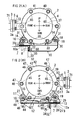
- Figs. 1 to 9 are views for illustrating an engine with an exhaust treatment device according to Embodiment of the present invention.
- an in-line multicylinder vertical diesel engine with an exhaust treatment device in which a DPF (51) is housed will be described.
- the installing direction of a crankshaft is the front and rear direction
- a flywheel (1) is placed on the rear side
- the width direction of the engine is the lateral direction.
- a cylinder head (54) in an upper part of a cylinder block (53) is assembled, a head cover (55) is assembled to an upper part of the cylinder head (54), a gear case (56) is assembled to a front part of the cylinder block (53), an engine cooling fan (67) is arranged on the front side of the gear case (56), a flywheel housing (57) is assembled to a rear part of the cylinder block (53), and an oil pan (58) is assembled to a lower part of the cylinder block (53).
- a gear case (56) is assembled to a front part of the cylinder block (53)
- an engine cooling fan (67) is arranged on the front side of the gear case (56)
- a flywheel housing (57) is assembled to a rear part of the cylinder block (53)
- an oil pan (58) is assembled to a lower part of the cylinder block (53).
- an exhaust manifold (59) is assembled on the left side of the cylinder head (54)
- an intake manifold (73) is assembled on the right side of the cylinder head (54)
- a supercharger (60) is assembled to an upper part of the exhaust manifold (59).
- a sideways exhaust treatment device (2) is arranged on the rear upper side of the engine.
- An engine exhaust outlet flange (3) is arranged on the one side of the engine, an exhaust inlet flange (5) is arranged in a one-side portion (4) of the exhaust treatment device (2), and the exhaust inlet flange (5) is attached to the engine exhaust outlet flange (3) by exhaust flange fastening tools (6) (6) (6).
- the engine exhaust outlet flange (3) is provided in a rear end of an engine exhaust outlet pipe (71) attached to the supercharger (60), and the exhaust inlet flange (5) is provided in a front end of an exhaust inlet pipe (72) extended forward from the one-end side portion (4) of the exhaust treatment device (2).
- a one-side support stay mount surface (8) and an other-side support stay mount surface (9) are provided in an engine rear upper portion (7).
- a front portion (10a) of a one-side support stay (10) is mounted on the one-side support stay mount surface (8) and attached by a one-side support stay fastening tool (11).
- a front portion (12a) of an other-side support stay (12) is mounted on the other-side support stay mount surface (9) and attached by an other-side support stay fastening tool (13).
- the exhaust treatment device (2) is supported on the engine rear upper portion (7) via the one-side support stay (10) and the other-side support stay (12).
- a DOC (52) and the DPF (51) are housed inside the exhaust treatment device (2).
- the DOC (52) is arranged on the upstream side and the DPF (51) is arranged on the downstream side.
- the DOC (52) is an abbreviation of a diesel oxidation catalyst
- the DPF (51) is an abbreviation of a diesel particulate filter.
- the DPF (51) catches PMs (particle matters) contained in exhaust, and the DOC (52) oxidizes unburnt fuel blown from a combustion chamber and unburnt fuel jetted in an exhaust route.
- the exhaust treatment device (2) may be an exhaust muffler or a catalytic converter.
- one-side support portions (14) (14) are provided in the one-side support stay (10), and other-side support portions (15) (15) are provided in the other-side support stay (12).
- One-side supported portions (16) (16) and other-side supported portions (17) (17) are provided in the exhaust treatment device (2).
- a cutout groove (20) having an opening (23) in one end is provided in the front portion (12a) of the other-side support stay (12), and the other-side support stay fastening tool (13) attached to the other-side support stay mount surface (9) is inserted into the cutout groove (20).
- one-side temporary mount portions (22) (22) are provided in the one-side support stay (10).
- the one-side portion (4) of the exhaust treatment device (2) before being attached to the engine exhaust outlet flange (3) and the one-side support stay (10) can be temporarily mounted onto the one-side temporary mount portions (22) (22).
- Rotation moment of the one-side support stay (10) generated by a load of the one-side portion (4) of the exhaust treatment device (2) is received by the one-side support stay fastening tool (11) via an edge part of a fastening tool insertion hole (62) to be described later, so that the load of the one-side portion (4) of the exhaust treatment device (2) is supported by the one-side support stay (10).
- the exhaust flange fastening tools (6) (6) (6) are bolts passing through bolt insertion holes (5a) (5a) (5a) of the exhaust inlet flange (5) and being screwed into screw holes of the engine exhaust outlet flange (3).
- Three bolt insertion holes (5a) (5a) (5a) are arranged at a distant angle of 120° in the circumferential direction of the exhaust inlet flange (5) by the angle, and three exhaust flange fastening tools (6) (6) (6) are also arranged.
- the one-side support stay fastening tool (11) is a bolt passing through a fastening tool insertion hole of the front portion (10a) of the one-side support stay (10) and being screwed into a screw hole of the one-side support stay mount surface (8).
- Both the one-side supported portion fastening tools (18) (18) and the other-side supported portion fastening tools (19) (19) are bolt nuts.
- the cutout groove (20) of the other-side support stay (12) is formed sideways. Thereby, upon mounting the front portion (12a) of the other-side support stay (12) onto the other-side support stay mount surface (9), the other-side support stay fastening tool (13) is brought into the cutout groove (20) sideways from the opening (23), so that a lateral position of the other-side support stay (12) is adjustable.
- the cutout groove (20) is parallel to a laterally horizontal axis which is orthogonal to a crankshaft axis (70) serving as a front-rear horizontal axis.
- the opening (23) is provided on the other side of the cutout groove (20). As shown in Fig.
- the engine exhaust outlet flange (3) is formed so as to face the rear side and the exhaust inlet flange (5) is formed so as to face the front side.
- an other-side stay pressure receiving surface (34) is provided in an engine rear surface (32) and an other-side support stay positioning piece (36) is provided in the other-side support stay (12).
- the other-side support stay positioning piece (36) is abutted with the other-side stay pressure receiving surface (34) from the rear side, the other-side support stay (12) is positioned in the front and rear direction.
- All the engine exhaust outlet flange (3), the exhaust inlet flange (5), the other-side stay pressure receiving surface (34), and the other-side support stay positioning piece (36) are parallel to a front-rear vertical plane which is orthogonal to the crankshaft axis (70) serving as the front-rear horizontal axis.
- mating surfaces (24) (24) are provided in the other-side support portions (15) (15) of the other-side support stay (12), mating surfaces (25) (25) are provided in the other-side supported portions (17) (17) of the exhaust treatment device (2), and both the mating surfaces (24) (25) are directed to the side so as to face each other.
- the mating surfaces (24) (24) of the other-side support portions (15) (15) of the other-side support stay (12) can be overlapped with the mating surfaces (25) (25) of the other-side supported portions (17) (17) of the exhaust treatment device (2) from the side.
- the other-side supported portion fastening tools (19) (19) can be fastened while axes thereof are placed sideways. Both the mating surfaces (24) (25) are formed along the vertical plane which is orthogonal to the front-rear axis.
- the pair of front and rear other-side supported portion fastening tools (19) (19) is provided.
- the former is a front-rear long hole, and the latter is a circular hole.
- These holes are overlapped side by side, and the front other-side supported portion fastening tool (19) is placed at a position where the front-rear long hole and the circular hole are overlapped on the front side.
- the former may be a circular hole and the latter may be a front-rear long hole.
- the front-rear long hole is parallel to the crankshaft axis (70) serving as the front-rear horizontal axis.
- the former is a front-rear long hole, and the latter is an up-down long hole.
- These holes are crossed and overlapped side by side, and the rear other-side supported portion fastening tool (19) is placed at a position where the front-rear long hole and the up-down long hole are crossed on the rear side.
- the former may be an up-down long hole and the latter may be a front-rear long hole.
- the front-rear long hole is parallel to the crankshaft axis (70) serving as the front-rear horizontal axis, and the up-down long hole is parallel to the vertical axis.
- the fastening tool insertion hole (62) serving as a lateral long hole is provided in the front portion (10a) of the one-side support stay (10).
- the one-side support stay fastening tool (11) is inserted into the fastening tool insertion hole (62) serving as the lateral long hole, and the one-side support stay (10) can be attached to the one-side support stay mount surface (8) by the one-side support stay fastening tool (11) in such a manner that a lateral position is adjustable.
- a one-side stay pressure receiving surface (33) is provided in the engine rear surface (32), and a one-side support stay positioning piece (35) is provided in the front portion (10a) of the one-side support stay (10).
- the one-side support stay (10) is positioned in the front and rear direction.
- Both the one-side stay pressure receiving surface (33) and the one-side support stay positioning piece (35) are parallel to the front-rear vertical plane which is orthogonal to the crankshaft axis (70) serving as the front-rear horizontal axis.
- mating surfaces (28) (28) are provided in the one-side support portions (14) (14) of the one-side support stay (10), mating surfaces (29) (29) are provided in the one-side supported portions (16) (16) of the exhaust treatment device (2), and both the mating surfaces (28) (29) are directed to the side so as to face each other.
- the mating surfaces (28) (28) of the one-side support portions (14) (14) can be overlapped with the mating surfaces (29) (29) of the one-side supported portions (16) (16) of the exhaust treatment device (2) from the side.
- the one-side supported portion fastening tools (18) (18) can be attached while axes thereof are placed sideways. Both the mating surfaces (28) (29) are formed along the vertical plane which is orthogonal to the lateral axis.
- the pair of front and rear one-side supported portion fastening tools (18) (18) is provided.
- a fastening tool insertion hole (30) of the one-side supported portion (16) through which the front one-side supported portion fastening tool (18) is inserted and a fastening tool insertion hole (31) of the one-side support portion (14)
- the former is a front-rear long hole
- the latter is an up-down long hole.
- the former may be an up-down long hole and the latter may be a front-rear long hole.
- the front-rear long hole is parallel to the crankshaft axis (70) serving as the front-rear horizontal axis, and the up-down long hole is parallel to the vertical axis.
- the former is a front-rear long hole, and the latter is an up-down long hole.
- These holes are crossed and overlapped side by side, and the rear one-side supported portion fastening tool (18) is placed at a position where the front-rear long hole and the up-down long hole are crossed on the rear side.
- the former may be an up-down long hole and the latter may be a front-rear long hole.
- the front-rear long hole is parallel to the crankshaft axis (70) serving as the front-rear horizontal axis, and the up-down long hole is parallel to the vertical axis.
- a part of the rotation moment of the other-side support stay (12) generated by the load of the other-side portion (50) of the exhaust treatment device (2) can be received by the other-side stay pressure receiving surface (34) of the engine rear surface (32) via the other-side support stay positioning piece (36), and a part of the rotation moment of the one-side support stay (10) generated by the load of the one-side portion (4) of the exhaust treatment device (2) can be received by the one-side stay pressure receiving surface (33) of the engine rear surface (32) via the one-side support stay positioning piece (35).
- a left vertical plate (61) is bent and formed downward from a left edge part of a horizontal plate (64)
- the one-side support stay positioning piece (35) is bent and formed leftward from a rear edge of the left vertical plate (61)
- the pair of front and rear one-side support portions (14) (14) and the one-side temporary mount portions (22) (22) are bent and formed upward from a right edge part of the horizontal plate (64).
- the fastening tool insertion hole (62) is provided in the front portion (10a) of the one-side support stay (10), and the fastening tool insertion hole (62) is formed to be the lateral long hole.
- the fastening tool insertion holes (31) (31) are also provided in the one-side support portions (14) (14), and the fastening tool insertion holes (31) (31) are formed to be up-down long holes.
- a fastening tool insertion hole (63) is also provided in the one-side support stay positioning piece (35), and the fastening tool insertion hole (63) is formed to be a lateral long hole.
- the pair of front and rear other-side support portions (15) (15) is bent and formed upward from a left edge part of a horizontal plate (48).
- the fastening tool insertion holes (27) (27) are provided in the other-side support portions (15) (15), the front fastening tool insertion hole (27) is a circular hole, and the rear fastening tool insertion hole (27) is an up-down long hole.
- a fastening nut (66) which is concentric with the fastening tool insertion hole (27) is fixed to the front other-side support portion (15) by welding.
- the fastening nut (66) is combined with a bolt so as to form the other-side supported portion fastening tool (19).
- the front portion (12a) of the other-side support stay (12) is formed to be wider than a rear portion and provided with the cutout groove (20) having the opening (23) on the right side, and the other-side support stay positioning piece (36) is bent and formed downward from a rear edge part of the front portion.
- a fastening tool insertion hole (64) is provided in the other-side support stay positioning piece (36), and the fastening tool insertion hole (64) is formed to be a lateral long hole.
- a casing of the exhaust treatment device (2) includes a plurality of dividable casing parts (37) (38) (39), and coupling flanges (40) (41) (42) (43) are provided at divided points of the plurality of casing parts (37) (38) (39).
- the one-side supported portions (16) (16) and the other-side supported portions (17) (17) of the exhaust treatment device (2) are extended from the coupling flanges (41) (42).
- the coupling flanges (41) (42) are coupling flanges in both ends of the DPF housing casing part (38) to be described later.
- the one-side supported portions (16) (16) and the other-side supported portions (17) (17) of the exhaust treatment device (2) may be extended from the coupling flange (40) of the exhaust inlet flange (5) and the coupling flange (43) of the exhaust outlet side casing part (39).
- the casing of the exhaust treatment device (2) includes the exhaust inlet side casing part (37) provided with the exhaust inlet flange (5), the DPF housing casing part (38), and the exhaust outlet side casing part (39) provided with an exhaust outlet pipe (44).
- the exhaust inlet side casing part (37) and the exhaust outlet side casing part (39) are detachable from the DPF housing casing part (38).
- the exhaust outlet pipe (44) protrudes from an outer peripheral surface of the exhaust outlet side casing part (39), and the coupling flanges (42) (43) at the divided point of the DPF housing casing part (38) and the exhaust outlet side casing part (39) are coupled by fastening of a plurality of flange fastening tools (45) (45) (45) (45) (45).
- a plurality of flange fastening tools 45) (45) (45) (45) (45) (45) (45) (45).
- a plurality of fastened portions (46) (46) (46) (46) (46) (46) (46) is arranged in the coupling flange (42) of the DPF housing casing part (38) at an equal distant angle in the circumferential direction of the coupling flange, and a plurality of fastened portions (47) (47) (47) (47) (47) (47) (47) (47) is arranged in the coupling flange (43) of the exhaust outlet side casing part (39) at an equal distant angle in the circumferential direction of the coupling flange.
- a reinforcing portion (49) facing the other-side support portion (15) is bent and formed upward from a laterally outer edge of the horizontal piece (42), and the reinforcing portion (49) is positioned on the laterally inner side of the exhaust outlet pipe (44) when seen from the rear side of the engine.
- the coupling flanges (40) (41) at the divided point of the DPF housing casing part (38) and the exhaust inlet side casing part (37) are coupled by fastening of a plurality of flange fastening tools (65) (65) (65) (65) (65).
- Each flange fastening tool (65) is arranged at an equal distant angle in the circumferential direction of the coupling flanges (40) (41).
- the front portion (10a) of the one-side support stay (10) is mounted onto the one-side support stay mount surface (8) and attached by the one-side support stay fastening tool (11).
- the one-side support stay positioning piece (35) is abutted with the one-side stay pressure receiving surface (33) from the rear side and attached by a one-side positioning piece fastening tool (68).
- the other-side support stay fastening tool (13) is attached to the other-side support stay mount surface (9).
- the other-side support portions (15) (15) of the other-side support stay (12) are loosely attached to the other-side supported portions (17) (17) of the exhaust treatment device (2) by the other-side supported portion fastening tools (19) (19), so as to oscillatably couple the other-side support stay (12) to the exhaust treatment device (2).
- the one-side portion (4) of the exhaust treatment device (2) is lowered taking the front other-side supported portion fastening tool (19) supported by the other-side support stay (12) shown in Fig. 2(B) as a supporting point so as to temporarily mount the one-side portion (4) of the exhaust treatment device (2) before being attached to the engine exhaust outlet flange (3) and the one-side support stay (10) onto the one-side temporary mount portions (22) (22).
- the one-side portion (4) of the exhaust treatment device (2) is mounted by mounting the lower pair of front and rear flange fastening tools (65) (65) for coupling the coupling flanges (40) (41) at the divided point of the exhaust inlet side casing part (37) and the DPF housing casing part (38) onto the one-side temporary mount portions (22) (22).
- the one-side portion (4) of the exhaust treatment device (2) temporarily mounted on the one-side temporary mount portions (22) (22) shown in Fig. 2(A) is lifted taking the front other-side supported portion fastening tool (19) supported by the other-side support stay (12) shown in Fig. 1 (B) as a supporting point so as to attach the exhaust inlet flange (5) to the engine exhaust outlet flange (3) by the exhaust flange fastening tools (6) (6) (6) as shown in Fig. 1 (A) .
- the gasket (3a) upon attaching the exhaust inlet flange (5) to the engine exhaust outlet flange (3), the gasket (3a) is nipped between the engine exhaust outlet flange (3) and the exhaust inlet flange (5) and the exhaust inlet flange (5) is attached to the engine exhaust outlet flange (3) by the exhaust flange fastening tools (6) (6) (6), so that the exhaust treatment device (3) is positioned in the front and rear direction.
- the exhaust inlet flange (5) is attached to the engine exhaust outlet flange (3) by temporary fastening of the exhaust flange fastening tools (6) (6) (6).
- the other-end side portion (50) of the exhaust treatment device (2) is oscillatable taking any exhaust flange fastening tool (6) as a supporting point.
- the temporary fastening indicates a fastening state that an object to be fastened is not moved in the fastening direction of a fastening tool but slidable in the direction which is orthogonal to the fastening direction.
- regular fastening to be described later indicates a fastening state that the object to be fastened is neither moved in the fastening direction of the fastening tool nor slidable in the direction which is orthogonal to the fastening direction.
- the other-side support stay positioning piece (36) is abutted with the other-side stay pressure receiving surface (34) from the rear side, so that the other-side support stay (12) is positioned in the front and rear direction.
- the mating surfaces (24) (24) of the other-side support portions (15) (15) of the other-side support stay (12) are overlapped with the mating surfaces (25) (25) of the other-side supported portions (17) (17) of the exhaust treatment device (2) from the side.
- the other-side supported portion fastening tools (19) (19) are fastened while the axes thereof are placed sideways. This fastening is performed by the temporary fastening.
- the load of the one-side portion (4) of the exhaust treatment device (2) is supported by the exhaust flange fastening tool (6) positioned in the up and down direction and the lateral direction by attachment to the engine exhaust outlet flange (3), and the load of the other-side portion (50) of the exhaust treatment device (2) is supported by the other-side support stay (12) via the front other-side supported portion fastening tool (19) whose up-down position is set at the overlapping position of the circular hole and the front-rear long hole on the front side.
- the exhaust treatment device (2) is retained at a predetermined attachment posture positioned in the front and rear direction, the lateral direction, and the up and down direction.
- the rear other-side supported portion fastening tool (19) is set at the crossing position of the front-rear long hole and the up-down long hole on the rear side. After that, fastening of the pair of front and rear other-side supported portion fastening tools (19) (19) is enhanced, so that the other-side supported portions (17) (17) are fixed to the other end-side support portions (15) (15).
- This fastening is performed by the regular fastening.
- the fastening tools are fastened by the temporary fastening. When the positioning and the position setting are finished, the fastening tools are fastened by the regular fastening.
- One example of specific fastening procedure is as follows.
- the temporary fastening of the front other-side supported portion fastening tool (19), the temporary fastening of the rear other-side supported portion fastening tool (19), and the temporary fastening of the other-side support stay fastening tool (13) are performed in order, and the positioning in the front and rear direction and the position setting in the lateral direction of the other-side support stay (12) are performed, the regular fastening of the other-side positioning piece fastening tool (69), the regular fastening of the other-side support stay fastening tool (13), the regular fastening of the front other-side supported portion fastening tool (19), and the regular fastening of the rear other-side supported portion fastening tool (19) are performed in order.
- the regular fastening of the exhaust flange fastening tools (6) (6) (6) is performed.
- the one-side support stay fastening tool (11) is inserted into the fastening tool insertion hole (62) serving as the lateral long hole, and the one-side support stay (10) is attached to the one-side support stay mount surface (8) by the one-side support stay fastening tool (11) in such a manner that the lateral position is adjustable.
- the one-side support stay fastening tool (11) is inserted into the fastening tool insertion hole (62) serving as the lateral long hole, and the one-side support stay (10) is attached to the one-side support stay mount surface (8) by the one-side support stay fastening tool (11) in such a manner that the lateral position is adjustable.
- the one-side support stay positioning piece (35) is abutted with the one-side stay pressure receiving surface (33) from the rear side, so that the one-side support stay (10) is positioned in the front and rear direction.
- the mating surfaces (28) (28) of the one-side support portions (14) (14) of the one-side support stay (10) are overlapped with the mating surfaces (29) (29) of the one-side supported portions (16) (16) of the exhaust treatment device (2) from the side.
- the one-side supported portion fastening tools (18) (18) are attached while the axes thereof are placed sideways.
- the mating surfaces (28) (28) of the one-side support portions (14) (14) of the one-side support stay (10) positioned in the front and rear direction are overlapped with the mating surfaces (29) (29) of the one-side supported portions (16) (16) of the exhaust treatment device (2) retained at the predetermined attachment posture from the side.
- the crossing position of the up-down long hole and the front-rear long hole on the front side is set and the crossing position of the up-down long hole and the front-rear long hole on the rear side is set.
- the pair of front and rear one-side supported portion fastening tools (18) (18) is inserted and attached to the set pair of front and rear crossing positions, so that the one-side supported portions (16) (16) are fixed to the one-side support portions (14) (14).
- the fastening tools are fastened by the temporary fastening.
- the fastening tools are fastened by the regular fastening.
- One example of specific procedure is as follows.
- the temporary fastening of the one-side positioning piece fastening tool (68), the temporary fastening of the one-side support stay fastening tool (11), and the temporary fastening of the rear one-side supported portion fastening tool (18) are performed in order, and the positioning in the front and rear direction and the position setting in the lateral direction of the one-side support stay (10) are performed, the regular fastening of the front one-side supported portion fastening tool (18), the regular fastening of the one-side positioning piece fastening tool (68), the regular fastening of the one-side support stay fastening tool (11), and the regular fastening of the rear one-side supported portion fastening tool (18) are performed in order.
- a part of the rotation moment of the other-side support stay (12) generated by the load of the other-side portion (50) of the exhaust treatment device (2) is received by the other-side stay pressure receiving surface (34) of the engine rear surface (32) via the other-side support stay positioning piece (36), and a part of the rotation moment of the one-side support stay (10) generated by the load of the one-side portion (4) of the exhaust treatment device (2) is received by the one-side stay pressure receiving surface (33) of the engine rear surface (32) via the one-side support stay positioning piece (35).
Landscapes
- Engineering & Computer Science (AREA)
- Chemical & Material Sciences (AREA)
- Combustion & Propulsion (AREA)
- Mechanical Engineering (AREA)
- General Engineering & Computer Science (AREA)
- Chemical Kinetics & Catalysis (AREA)
- Transportation (AREA)
- Health & Medical Sciences (AREA)
- Toxicology (AREA)
- Exhaust Gas After Treatment (AREA)
- Processes For Solid Components From Exhaust (AREA)
- Exhaust Silencers (AREA)
- Cooling, Air Intake And Gas Exhaust, And Fuel Tank Arrangements In Propulsion Units (AREA)
- Exhaust Gas Treatment By Means Of Catalyst (AREA)
- Motor Or Generator Frames (AREA)
Abstract
Description
- The present invention relates to an engine with an exhaust treatment device and an attachment method for the exhaust treatment device, and in detail, relates to an engine with an exhaust treatment device with which an attachment task of the exhaust treatment device to an engine rear upper portion becomes simplified and an attachment method for the exhaust treatment device.
- Conventionally, as an engine with an exhaust treatment device, there is an engine with an exhaust treatment device, wherein the installing direction of a crankshaft is the front and rear direction, a flywheel is placed on the rear side, and the width direction of the engine is the lateral direction, a sideways exhaust treatment device is arranged on the rear upper side of the engine, an engine exhaust outlet flange is arranged on a one side of the engine, an exhaust inlet flange is arranged in a one-side portion of the exhaust treatment device, the exhaust inlet flange is attached to the engine exhaust outlet flange by exhaust flange fastening tools, a one-side support stay mount surface and an other-side support stay mount surface are provided in an engine rear upper portion, a front portion of a one-side support stay is mounted on the one-side support stay mount surface and attached by a one-side support stay fastening tool, and a front portion of an other-side support stay is mounted on the other-side support stay mount surface and attached by an other-side support stay fastening tool, so that the exhaust treatment device is supported on the engine rear upper portion via the one-side support stay and the other-side support stay (for example, refer to Patent Document 1).
- According to this type of engine, there is an advantage that the exhaust treatment device can be compactly arranged in a dead space in the engine rear upper portion.
However, this conventional technique has a problem since both the one-side support stay and the other-side support stay are welded to the exhaust treatment device as described in [0022] of the specification ofPatent Document 1. - Patent Document 1: Japanese Patent Laid-open Publication No.
2010-71175 - In the above conventional technique, both the one-side support stay and the other-side support stay are welded to the exhaust deice. Thus, during the attachment task of the exhaust treatment device to the engine rear upper portion, there is a need for always supporting the exhaust treatment device by an external support device such as a crane, so that the attachment task of the exhaust treatment device to the engine rear upper portion becomes complicated.
- An object of the present invention is to provide an engine with an exhaust treatment device with which an attachment task of the exhaust treatment device to an engine rear upper portion becomes simplified and an attachment method for the exhaust treatment device.
- A particular matter of the invention according to
claim 1 is as follows.
An engine with an exhaust treatment device, wherein: as shown inFigs. 1 (A) and 1 (B) , the installing direction of a crankshaft is the front and rear direction, a flywheel (1) is placed on the rear side, and the width direction of the engine is the lateral direction; a sideways exhaust treatment device (2) is arranged on the rear upper side of the engine; an engine exhaust outlet flange (3) is arranged on a one side of the engine, an exhaust inlet flange (5) is arranged in a one-side portion (4) of the exhaust treatment device (2), and the exhaust inlet flange (5) is attached to the engine exhaust outlet flange (3) by exhaust flange fastening tools (6) (6) (6); and a one-side support stay mount surface (8) and an other-side support stay mount surface (9) are provided in an engine rear upper portion (7), a front portion (10a) of a one-side support stay (10) is mounted on the one-side support stay mount surface (8) and attached by a one-side support stay fastening tool (11), and a front portion (12a) of an other-side support stay (12) is mounted on the other-side support stay mount surface (9) and attached by an other-side support stay fastening tool (13), so that the exhaust treatment device (2) is supported on the engine rear upper portion (7) via the one-side support stay (10) and the other-side support stay (12), - wherein: as shown in
Figs. 1 (A) and 1 (B) , one-side support portions (14) (14) are provided in the one-side support stay (10), and other-side support portions (15) (15) are provided in the other-side support stay (12); one-side supported portions (16) (16) and other-side supported portions (17) (17) are provided in the exhaust treatment device (2); upon attaching the one-side supported portions (16) (16) of the exhaust treatment device (2) to the one-side support portions (14) (14) of the one-side support stay (10) by one-side supported portion fastening tools (18) (18), and attaching the other-side supported portions (17) (17) of the exhaust treatment device (2) to the other-side support portions (15) (15) of the other-side support stay (12) by other-side supported portion fastening tools (19) (19); - as shown in
Fig. 1 (A) , by providing a cutout groove (20) having an opening (23) in one end in the front portion (12a) of the other-side support stay (12), and inserting the other-side support stay fastening tool (13) attached to the other-side support stay mount surface (9) into the cutout groove (20); in a case where the other-side support stay fastening tool (13) is brought into the cutout groove (20) from the opening (23) while guiding the front portion (12a) of the other-side support stay (12) by the other-side support stay mount surface (9), rotation moment of the other-side support stay (12) generated by a load of an other-side portion (50) of the exhaust treatment device (2) is received by the other-side support stay fastening tool (13) via an edge portion (21) of the cutout groove (20), so that the load of the other-side portion (50) of the exhaust treatment device (2) is capable of being supported by the other-side support stay (12); and - as shown in
Fig. 2(A) , by providing one-side temporary mount portions (22) (22) in the one-side support stay (10); the one-side portion (4) of the exhaust treatment device (2) before being attached to the engine exhaust outlet flange (3) and the one-side support stay (10) is capable of being temporarily mounted on the one-side temporary mount portions (22) (22). - A particular matter of the invention according to
claim 11 is as follows.
An attachment method for an exhaust treatment device for attaching the exhaust treatment device (2) of the engine with the exhaust treatment device according toclaim 1 to the engine rear upper portion (7), wherein the method comprises the steps of: as shown inFigs. 1 (A) and 1 (B) , mounting the front portion (10a) of the one-side support stay (10) onto the one-side support stay mount surface (8) and attaching by the one-side support stay fastening tool (11); attaching the other-side support stay fastening tool (13) to the other-side support stay mount surface (9); loosely attaching the other-side support portions (15) (15) of the other-side support stay (12) to the other-side supported portions (17) (17) of the exhaust treatment device (2) by the other-side supported portion fastening tools (19) (19), so as to oscillatably couple the other-side support stay (12) to the exhaust treatment device (2); - as shown in
Fig. 1 (A) , by bringing the other-side support stay fastening tool (13) into the cutout groove (20) from the opening (23) while guiding the front portion (12a) of the other-side support stay (12) by the other-side support stay mount surface (9), receiving the rotation moment of the other-side support stay (12) generated by the load of the other-side portion (50) of the exhaust treatment device (2) by the other-side support stay fastening tool (13) via the edge portion (21) of the cutout groove (20) so as to support the load of the other-side portion (50) of the exhaust treatment device (2) by the other-side support stay (12); - lowering the one-side portion (4) of the exhaust treatment device (2) taking the other-side supported portion fastening tool (19) supported by the other-side support stay (12) shown in
Fig. 1 (B) as a supporting point so as to temporarily mount the one-side portion (4) of the exhaust treatment device (2) before being attached to the engine exhaust outlet flange (3) and the one-side support stay (10) onto the one-side temporary mount portions (22) (22); and - lifting the one-side portion (4) of the exhaust treatment device (2) temporarily mounted on the one-side temporary mount portions (22) (22) shown in
Fig. 2(A) taking the other-side supported portion fastening tool (19) supported by the other-side support stay (12) shown inFig. 1(B) as a supporting point so as to attach the exhaust inlet flange (5) to the engine exhaust outlet flange (3) by the exhaust flange fastening tools (6) (6) (6) as shown inFig. 1 (A) . - The invention according to
claim 1 exerts the following effect.
«Effect» An attachment task of the exhaust treatment device to the engine rear upper portion becomes simplified.
With the invention according toclaim 1, as in the invention according toclaim 11, as shown inFigs. 1 (A) and 1 (B) , during the attachment task of the exhaust treatment device (2) to the engine rear upper portion (7), the load of the other-side portion (50) of the exhaust treatment device (2) can be supported by the other-side support stay (12) and the load of the one-side portion (4) of the exhaust treatment device (2) can be supported by the one-side support stay (10). Thus, there is no need for supporting the exhaust treatment device (2) by an external support device such as a crane, so that the attachment task of the exhaust treatment device (2) to the engine rear upper portion (7) becomes simplified. - «Effect» A support task of the other-side portion of the exhaust treatment device is simple.
With the invention according toclaim 1, as in the invention according toclaim 11, as shown inFig. 1(A) , by bringing the other-side support stay fastening tool (13) into the cutout groove (20) from the opening (23) while guiding the front portion (12a) of the other-side support stay (12) by the other-side support stay mount surface (9), the load of the other-side portion (50) of the exhaust treatment device (2) can be supported by the other-side support stay (12). Thus, the support task of the other-side portion (50) of the exhaust treatment device (2) is simple. - The invention according to
claim 2 exerts the following effect in addition to the effect of the invention according toclaim 1.
<<Effect>> The other-side supported portion fastening tools can be prevented from being loosened by vibration of the engine.
With the invention according toclaim 2, as in the invention according toclaim 12, as shown inFigs. 1(A) and 1(B) , for adjusting a lateral position of the other-side support stay (12), mating surfaces (24) (24) of the other-side support portions (15) (15) of the other-side support stay (12) can be overlapped with mating surfaces (25) (25) of the other-side supported portions (17) (17) of the exhaust treatment device (2) from the side, and the other-side supported portion fastening tools (19) (19) can be fastened while axes thereof are placed sideways. Thus, the other-side support portions (15) (15) and the other-side supported portions (17) (17) can be brought into a proper attachment posture where both the mating surfaces (24) (25) are closely attached, and these can be properly fastened by the other-side supported portion fastening tools (19) (19) from both the sides. Therefore, the other-side supported portion fastening tools (19) (19) can be prevented from being loosened by the vibration of the engine. - The invention according to
claim 3 exerts the following effect in addition to the effect of the invention according toclaim 2.
<<Effect>> A position setting task of the rear other-side supported portion fastening tool is simple.
With the invention according toclaim 3, as in the invention according toclaim 13, as shown inFigs. 1 (A) and 1 (B) , the load of the one-side portion (4) of the exhaust treatment device (2) is supported by the exhaust flange fastening tool (6) positioned in the up and down direction and the lateral direction by attachment to the engine exhaust outlet flange (3), the load of the other-side portion (50) of the exhaust treatment device (2) is supported by the other-side support stay (12) via the front other-side supported portion fastening tool (19) whose up-down position is set at an overlapping position of a circular hole and a front-rear long hole on the front side, and the exhaust treatment device (2) is retained at a predetermined attachment posture positioned in the front and rear direction, the lateral direction, and the up and down direction. Thereby, as shown inFig. 2(B) , the rear other-side supported portion fastening tool (19) can be set at a crossing position of a front-rear long hole and an up-down long hole on the rear side. Thus, the position setting task of the rear other-side supported portion fastening tool (19) is simple. - The invention according to
claim 4 exerts the following effect in addition to the effect of the invention according toclaim
<<Effect>> The one-side supported portion fastening tools can be prevented from being loosened by the vibration of the engine.
With the invention according toclaim 4, as in the invention according toclaim 14, as shown inFigs. 1 (A) and 1 (B) , for adjusting a lateral position of the one-side support stay (10), mating surfaces (28) (28) of the one-side support portions (14) (14) of the one-side support stay (10) can be overlapped with mating surfaces (29) (29) of the one-side supported portions (16) (16) of the exhaust treatment device (2) from the side, and the one-side supported portion fastening tools (18) (18) can be fastened while axes thereof are placed sideways. Thus, the one-side support portions (14) (14) and the one-side supported portions (16) (16) can be brought into a proper attachment posture where both the mating surfaces (28) (29) are closely attached, and these can be properly fastened by the one-side supported portion fastening tools (18) (18) from both the sides. Therefore, the one-side supported portion fastening tools (18) (18) can be prevented from being loosened by the vibration of the engine. - The invention according to
claim 5 exerts the following effect in addition to the effect of the invention according toclaim 4.
<<Effect>> A position setting task of the pair of front and rear one-side supported portion fastening tools is simple.
With the invention according toclaim 5, as in the invention according toclaim 15, as shown inFig. 1 (A) , by overlapping the mating surfaces (28) (28) of the one-side support portions (14) (14) of the one-side support stay (10) whose front-rear position is set with the mating surfaces (29) (29) of the one-side supported portions (16) (16) of the exhaust treatment device (2) retained at a predetermined attachment posture from the side, as shown inFig. 2(A) , a crossing position of an up-down long hole and a front-rear long hole on the front side is set and a crossing position of an up-down long hole and a front-rear long hole on the rear side is set, and the pair of front and rear one-side supported portion fastening tools (18) (18) is inserted and attached to the set pair of front and rear crossing positions, so that the one-side supported portions (16) (16) can be fixed to the one-side support portions (14) (14). Thus, the position setting task of the pair of front and rear one-side supported portion fastening tools (18) (18) is simple. - The invention according to
claim 6 exerts the following effect in addition to the effect of the invention according to any ofclaims 2 to 5.
«Effect» The exhaust treatment device is stably supported on the engine rear upper portion.
With the invention according toclaim 6, as in the invention according toclaim 16, as shown inFigs. 2(A) and 2(B) , a part of the rotation moment of the other-side support stay (12) generated by the load of the other-side portion (50) of the exhaust treatment device (2) can be received by an other-side stay pressure receiving surface (34) of an engine rear surface (32) via an other-side support stay positioning piece (36), and a part of rotation moment of the one-side support stay (10) generated by the load of the one-side portion (4) of the exhaust treatment device (2) can be received by a one-side stay pressure receiving surface (33) of the engine rear surface (32) via a one-side support stay positioning piece (35). Thus, the exhaust treatment device (2) is stably supported on the engine rear upper portion (7) via the other-side support stay (12) and the one-side support stay (10). - The invention according to
claim 7 exerts the following effect in addition to the effect of the invention according to any ofclaims 1 to 6.
«Effect» The exhaust treatment device is stably supported on the engine rear upper portion.
As shown inFigs. 1(A) and 1(B) and2(A) and 2(B) , the one-side supported portions (16) (16) and the other-side supported portions (17) (17) of the exhaust treatment device (2) are extended from predetermined coupling flanges (41) (42). Thus, the exhaust treatment device (2) is stably supported on the engine rear upper portion (7) via the coupling flanges (41) (42) formed to be highly rigid. - The invention according to claim 8 exerts the following effect in addition to the effect of the invention according to
claim 7.
«Effect» Maintenance in a DPF and a casing of the exhaust treatment device can be easily performed.
As shown inFigs. 1(A) and 1(B) , an exhaust inlet side casing part (37) and an exhaust outlet side casing part (39) are detachable from a DPF housing casing part (38). Thus, the maintenance in a DPF (51) and the casing of the exhaust treatment device (2) can be easily performed. - The invention according to
claim 9 exerts the following effect in addition to the effect of the invention according to claim 8.
«Effect» The protruding direction of an exhaust outlet pipe applicable to a model in which the engine is mounted can be readily selected.
As shown inFig. 2(B) , by displacing the exhaust outlet side casing part (39) in the circumferential direction by the distant angle, matching fastened portions (47) (47) (47) (47) (47) (47) of a coupling flange (43) of the exhaust outlet side casing part (39) with fastened portions (46) (46) (46) (46) (46) (46) of the coupling flange (42) of the DPF housing casing part (38), and coupling the exhaust outlet side casing part (39) to the DPF housing casing part (38) by flange fastening tools (45) (45) (45) (45) (45) (45), the protruding direction of an exhaust outlet pipe (44) from an outer peripheral surface of the exhaust outlet side casing part (39) can be selected. Thus, the protruding direction of the exhaust outlet pipe (44) applicable to the model in which the engine is mounted can be freely selected. - The invention according to
claim 10 exerts the following effect in addition to the effect of the invention according toclaim 9.
«Effect» While enhancing rigidity of the other-side support stay in the vicinity of the other-side support portion by a reinforcing piece, contact between the reinforcing piece and the exhaust outlet pipe can be avoided.
As shown inFig. 1 (B) , a reinforcing portion (49) facing the other-side support portion (15) is bent and formed upward from a laterally outer edge of a horizontal piece (48), and the reinforcing portion (49) is positioned on the laterally inner side of the exhaust outlet pipe (44) when seen from the rear side of the engine. Thus, while enhancing the rigidity of the other-side support stay (12) in the vicinity of the other-side support portion (15) by the reinforcing portion (49), the contact between the reinforcing portion (49) and the exhaust outlet pipe (44) can be avoided. - The invention according to
claim 11 exerts the following effect.
<<Effect>> The attachment task of the exhaust treatment device to the engine rear upper portion becomes simplified.
As shown inFigs. 1 (A) and 1 (B) , during the attachment task of the exhaust treatment device (2) to the engine rear upper portion (7), the load of the other-side portion (50) of the exhaust treatment device (2) is supported by the other-side support stay (12) and the load of the one-side portion (4) of the exhaust treatment device (2) is supported by the one-side support stay (10). Thus, there is no need for supporting the exhaust treatment device (2) by an external support device such as a crane, so that the attachment task of the exhaust treatment device (2) to the engine rear upper portion (7) becomes simplified. - «Effect» The support task of the other-side portion of the exhaust treatment device is simple.
As shown inFig. 1(A) , by bringing the other-side support stay fastening tool (13) into the cutout groove (20) from the opening (23) while guiding the front portion (12a) of the other-side support stay (12) by the other-side support stay mount surface (9), the load of the other-side portion (50) of the exhaust treatment device (2) is supported by the other-side support stay (12). Thus, the support task of the other-side portion (50) of the exhaust treatment device (2) is simple. - The invention according to
claim 12 exerts the following effect in addition to the effect of the invention according toclaim 11.
«Effect» The other-side supported portion fastening tools can be prevented from being loosened by the vibration of the engine.
As shown inFigs. 1 (A) and 1 (B) , for adjusting the lateral position of the other-side support stay (12), the mating surfaces (24) (24) of the other-side support portions (15) (15) of the other-side support stay (12) are overlapped with the mating surfaces (25) (25) of the other-side supported portions (17) (17) of the exhaust treatment device (2) from the side, and the other-side supported portion fastening tools (19) (19) are attached while the axes thereof are placed sideways. Thus, the other-side support portions (15) (15) and the other-side supported portions (17) (17) can be brought into a proper attachment posture where both the mating surfaces (24) (25) are closely attached, and these can be properly fastened by the other-side supported portion fastening tools (19) (19) from both the sides. Therefore, the other-side supported portion fastening tools (19) (19) can be prevented from being loosened by the vibration of the engine. - The invention according to
claim 13 exerts the following effect in addition to the effect of the invention according toclaim 12.
<<Effect>> The position setting task of the rear other-side supported portion fastening tool is simple.
As shown inFigs. 1 (A) and 1 (B) , the load of the one-side portion (4) of the exhaust treatment device (2) is supported by the exhaust flange fastening tool (6) positioned in the up and down direction and the lateral direction by attachment to the engine exhaust outlet flange (3), the load of the other-side portion (50) of the exhaust treatment device (2) is supported by the other-side support stay (12) via the front other-side supported portion fastening tool (19) whose up-down position is set at the overlapping position of the circular hole and the front-rear long hole on the front side, and the exhaust treatment device (2) is retained at a predetermined attachment posture positioned in the front and rear direction, the lateral direction, and the up and down direction. Thereby, as shown inFig. 2(B) , the rear other-side supported portion fastening tool (19) is set at the crossing position of the front-rear long hole and the up-down long hole on the rear side. Thus, the position setting task of the rear other-side supported portion fastening tool (19) is simple. - The invention according to
claim 14 exerts the following effect in addition to the effect of the invention according to claim 12 or 13.
«Effect» The one-side supported portion fastening tools can be prevented from being loosened by the vibration of the engine.
As shown inFigs. 1 (A) and 1 (B) , for adjusting the lateral position of the one-side support stay (10), the mating surfaces (28) (28) of the one-side support portions (14) (14) of the one-side support stay (10) are overlapped with the mating surfaces (29) (29) of the one-side supported portions (16) (16) of the exhaust treatment device (2) from the side, and the one-side supported portion fastening tools (18) (18) are attached while the axes thereof are placed sideways. Thus, the one-side support portions (14) (14) and the one-side supported portions (16) (16) can be brought into a proper attachment posture where both the mating surfaces (28) (29) are closely attached, and these can be properly fastened by the one-side supported portion fastening tools (18) (18) from both the sides. Therefore, the one-side supported portion fastening tools (18) (18) can be prevented from being loosened by the vibration of the engine. - The invention according to
claim 15 exerts the following effect in addition to the effect of the invention according toclaim 14.
<<Effect>> A position setting operation of the pair of front and rear one-side supported portion fastening tools is simple.
As shown inFig. 1 (A) , by overlapping the mating surfaces (28) (28) of the one-side support portions (14) (14) of the one-side support stay (10) whose front-rear position is set with the mating surfaces (29) (29) of the one-side supported portions (16) (16) of the exhaust treatment device (2) retained at the predetermined attachment posture from the side, as shown inFig. 2(A) , the crossing position of the up-down long hole and the front-rear long hole on the front side is set and the crossing position of the up-down long hole and the front-rear long hole on the rear side is set, and the pair of front and rear one-side supported portion fastening tools (18) (18) is inserted and attached to the set pair of front and rear crossing positions, so that the one-side supported portions (16) (16) are fixed to the one-side support portions (14) (14). Thus, the position setting task of the pair of front and rear one-side supported portion fastening tools (18) (18) is simple. - The invention according to
claim 16 exerts the following effect in addition to the effect of the invention according to any ofclaims 12 to 15.
«Effect» The exhaust treatment device is stably supported on the engine rear upper portion.
With the invention according toclaim 16, as shown inFigs. 2(A) and 2(B) , a part of the rotation moment of the other-side support stay (12) generated by the load of the other-side portion (50) of the exhaust treatment device (2) is received by the other-side stay pressure receiving surface (34) of the engine rear surface (32) via the other-side support stay positioning piece (36), and a part of the rotation moment of the one-side support stay (10) generated by the load of the one-side portion (4) of the exhaust treatment device (2) is received by the one-side stay pressure receiving surface (33) of the engine rear surface (32) via the one-side support stay positioning piece (35). Thus, the exhaust treatment device (2) is stably supported on the engine rear upper portion (7) via the other-side support stay (12) and the one-side support stay (10). -
-
Fig. 1 (A) is a schematic plan view of an exhaust treatment device of a vertical engine with the exhaust treatment device according to Embodiment of the present invention and the vicinity thereof, andFig. 1 (B) is a schematic rear view. -
Fig. 2(A) is a view in whichFig. 1 (B) is seen from the left side, andFig. 2(B) is a view in whichFig. 1(B) is seen from the right side. -
Fig. 3(A) is a plan view of a first support stay used in the vertical engine with the exhaust treatment device according to Embodiment of the present invention,Fig. 3(B) is an arrow view of the B direction ofFig. 3(A), Fig. 3(C) is an arrow view of the C direction ofFig. 3(A), Fig. 3(D) is an arrow view of the D direction ofFig. 3(A), and Fig. 3(E) is an arrow view of the E direction ofFig. 3(A) . -
Fig. 4(A) is a plan view of a second support stay used in the vertical engine with the exhaust treatment device according to Embodiment of the present invention,Fig. 4(B) is an arrow view of the B direction ofFig. 4(A), Fig. 4(C) is an arrow view of the C direction ofFig. 4(A), Fig. 4(D) is an arrow view of the D direction ofFig. 4(A), and Fig. 4(E) is an arrow view of the E direction ofFig. 4(A) . -
Fig. 5 is a rear view of the vertical engine with the exhaust treatment device according to Embodiment of the present invention. -
Fig. 6 is a plan view of the engine ofFig. 5 . -
Fig. 7 is a one-side view of the engine ofFig. 5 . -
Fig. 8 is an other-side view of the engine ofFig. 5 . -
Fig. 9 is a front view of the engine ofFig. 5 . -
Figs. 1 to 9 are views for illustrating an engine with an exhaust treatment device according to Embodiment of the present invention. In Embodiment, an in-line multicylinder vertical diesel engine with an exhaust treatment device in which a DPF (51) is housed will be described.
As shown inFigs. 1 (A) and 1 (B) , the installing direction of a crankshaft is the front and rear direction, a flywheel (1) is placed on the rear side, and the width direction of the engine is the lateral direction.
As shown inFig. 7 , a cylinder head (54) in an upper part of a cylinder block (53) is assembled, a head cover (55) is assembled to an upper part of the cylinder head (54), a gear case (56) is assembled to a front part of the cylinder block (53), an engine cooling fan (67) is arranged on the front side of the gear case (56), a flywheel housing (57) is assembled to a rear part of the cylinder block (53), and an oil pan (58) is assembled to a lower part of the cylinder block (53).
As shown inFig. 6 , an exhaust manifold (59) is assembled on the left side of the cylinder head (54), an intake manifold (73) is assembled on the right side of the cylinder head (54), and a supercharger (60) is assembled to an upper part of the exhaust manifold (59). - In the following description of Embodiment, the one side indicates the left side, and the other side indicates the right side.
As shown inFigs. 1 (A) and 1 (B) , a sideways exhaust treatment device (2) is arranged on the rear upper side of the engine.
An engine exhaust outlet flange (3) is arranged on the one side of the engine, an exhaust inlet flange (5) is arranged in a one-side portion (4) of the exhaust treatment device (2), and the exhaust inlet flange (5) is attached to the engine exhaust outlet flange (3) by exhaust flange fastening tools (6) (6) (6).
The engine exhaust outlet flange (3) is provided in a rear end of an engine exhaust outlet pipe (71) attached to the supercharger (60), and the exhaust inlet flange (5) is provided in a front end of an exhaust inlet pipe (72) extended forward from the one-end side portion (4) of the exhaust treatment device (2).
A one-side support stay mount surface (8) and an other-side support stay mount surface (9) are provided in an engine rear upper portion (7). A front portion (10a) of a one-side support stay (10) is mounted on the one-side support stay mount surface (8) and attached by a one-side support stay fastening tool (11). A front portion (12a) of an other-side support stay (12) is mounted on the other-side support stay mount surface (9) and attached by an other-side support stay fastening tool (13). The exhaust treatment device (2) is supported on the engine rear upper portion (7) via the one-side support stay (10) and the other-side support stay (12). - As shown in
Fig. 1 (B) , a DOC (52) and the DPF (51) are housed inside the exhaust treatment device (2). The DOC (52) is arranged on the upstream side and the DPF (51) is arranged on the downstream side.
The DOC (52) is an abbreviation of a diesel oxidation catalyst, and the DPF (51) is an abbreviation of a diesel particulate filter.
In the exhaust treatment device (2), the DPF (51) catches PMs (particle matters) contained in exhaust, and the DOC (52) oxidizes unburnt fuel blown from a combustion chamber and unburnt fuel jetted in an exhaust route. A temperature of the exhaust is increased by oxidization heat, and the PMs accumulated in the DPF (51) are combusted, so that the DPF (51) is regenerated.
The exhaust treatment device (2) may be an exhaust muffler or a catalytic converter. - As shown in
Figs. 1 (A) and 1 (B) , one-side support portions (14) (14) are provided in the one-side support stay (10), and other-side support portions (15) (15) are provided in the other-side support stay (12).
One-side supported portions (16) (16) and other-side supported portions (17) (17) are provided in the exhaust treatment device (2).
Upon attaching the one-side supported portions (16) (16) of the exhaust treatment device (2) to the one-side support portions (14) (14) of the one-side support stay (10) by one-side supported portion fastening tools (18) (18) and attaching the other-side supported portions (17) (17) of the exhaust treatment device (2) to the other-side support portions (15) (15) of the other-side support stay (12) by other-side supported portion fastening tools (19) (19), the following processes are taken. - As shown in
Fig. 1 (A) , a cutout groove (20) having an opening (23) in one end is provided in the front portion (12a) of the other-side support stay (12), and the other-side support stay fastening tool (13) attached to the other-side support stay mount surface (9) is inserted into the cutout groove (20).
Thereby, in a case where the other-side support stay fastening tool (13) is brought into the cutout groove (20) from the opening (23) while guiding the front portion (12a) of the other-side support stay (12) by the other-side support stay mount surface (9), rotation moment of the other-side support stay (12) generated by a load of an other-side portion (50) of the exhaust treatment device (2) is received by the other-side support stay fastening tool (13) via an edge portion (21) of the cutout groove (20), so that the load of the other-side portion (50) of the exhaust treatment device (2) can be supported by the other-side support stay (12). - As shown in
Fig. 2(A) , one-side temporary mount portions (22) (22) are provided in the one-side support stay (10).
Thereby, the one-side portion (4) of the exhaust treatment device (2) before being attached to the engine exhaust outlet flange (3) and the one-side support stay (10) can be temporarily mounted onto the one-side temporary mount portions (22) (22).
Rotation moment of the one-side support stay (10) generated by a load of the one-side portion (4) of the exhaust treatment device (2) is received by the one-side support stay fastening tool (11) via an edge part of a fastening tool insertion hole (62) to be described later, so that the load of the one-side portion (4) of the exhaust treatment device (2) is supported by the one-side support stay (10).
As shown inFigs. 1 (A) and 1 (B) , the exhaust flange fastening tools (6) (6) (6) are bolts passing through bolt insertion holes (5a) (5a) (5a) of the exhaust inlet flange (5) and being screwed into screw holes of the engine exhaust outlet flange (3). Three bolt insertion holes (5a) (5a) (5a) are arranged at a distant angle of 120° in the circumferential direction of the exhaust inlet flange (5) by the angle, and three exhaust flange fastening tools (6) (6) (6) are also arranged.
The one-side support stay fastening tool (11) is a bolt passing through a fastening tool insertion hole of the front portion (10a) of the one-side support stay (10) and being screwed into a screw hole of the one-side support stay mount surface (8).
Both the one-side supported portion fastening tools (18) (18) and the other-side supported portion fastening tools (19) (19) are bolt nuts. - As shown in
Figs. 1 (A) and 1 (B) , the cutout groove (20) of the other-side support stay (12) is formed sideways. Thereby, upon mounting the front portion (12a) of the other-side support stay (12) onto the other-side support stay mount surface (9), the other-side support stay fastening tool (13) is brought into the cutout groove (20) sideways from the opening (23), so that a lateral position of the other-side support stay (12) is adjustable.
The cutout groove (20) is parallel to a laterally horizontal axis which is orthogonal to a crankshaft axis (70) serving as a front-rear horizontal axis. The opening (23) is provided on the other side of the cutout groove (20).
As shown inFig. 1 (A) , the engine exhaust outlet flange (3) is formed so as to face the rear side and the exhaust inlet flange (5) is formed so as to face the front side.
Thereby, upon attaching the exhaust inlet flange (5) to the engine exhaust outlet flange (3), in a case where a gasket (3a) is nipped between the engine exhaust outlet flange (3) and the exhaust inlet flange (5) and the exhaust inlet flange (5) is attached to the engine exhaust outlet flange (3) by the exhaust flange fastening tools (6) (6) (6), the exhaust treatment device (3) is positioned in the front and rear direction. - As shown in
Figs. 1 (A) and 1 (B) , an other-side stay pressure receiving surface (34) is provided in an engine rear surface (32) and an other-side support stay positioning piece (36) is provided in the other-side support stay (12).
Thereby, in a case where the other-side support stay positioning piece (36) is abutted with the other-side stay pressure receiving surface (34) from the rear side, the other-side support stay (12) is positioned in the front and rear direction.
All the engine exhaust outlet flange (3), the exhaust inlet flange (5), the other-side stay pressure receiving surface (34), and the other-side support stay positioning piece (36) are parallel to a front-rear vertical plane which is orthogonal to the crankshaft axis (70) serving as the front-rear horizontal axis. - As shown in
Figs. 1 (A) and 1 (B) , mating surfaces (24) (24) are provided in the other-side support portions (15) (15) of the other-side support stay (12), mating surfaces (25) (25) are provided in the other-side supported portions (17) (17) of the exhaust treatment device (2), and both the mating surfaces (24) (25) are directed to the side so as to face each other.
Thereby, for adjusting the lateral position of the other-side support stay (12), the mating surfaces (24) (24) of the other-side support portions (15) (15) of the other-side support stay (12) can be overlapped with the mating surfaces (25) (25) of the other-side supported portions (17) (17) of the exhaust treatment device (2) from the side.
The other-side supported portion fastening tools (19) (19) can be fastened while axes thereof are placed sideways.
Both the mating surfaces (24) (25) are formed along the vertical plane which is orthogonal to the front-rear axis. - As shown in
Fig. 1 (B) , the pair of front and rear other-side supported portion fastening tools (19) (19) is provided.
Among a fastening tool insertion hole (26) of the other-side supported portion (17) through which the front other-side supported portion fastening tool (19) is inserted and a fastening tool insertion hole (27) of the other-side support portion (15), the former is a front-rear long hole, and the latter is a circular hole. These holes are overlapped side by side, and the front other-side supported portion fastening tool (19) is placed at a position where the front-rear long hole and the circular hole are overlapped on the front side.
The former may be a circular hole and the latter may be a front-rear long hole.
The front-rear long hole is parallel to the crankshaft axis (70) serving as the front-rear horizontal axis. - Among a fastening tool insertion hole (26) of the other-side supported portion (17) through which the rear other-side supported portion fastening tool (19) is inserted and a fastening tool insertion hole (27) of the other-side support portion (15), the former is a front-rear long hole, and the latter is an up-down long hole. These holes are crossed and overlapped side by side, and the rear other-side supported portion fastening tool (19) is placed at a position where the front-rear long hole and the up-down long hole are crossed on the rear side.
The former may be an up-down long hole and the latter may be a front-rear long hole.
The front-rear long hole is parallel to the crankshaft axis (70) serving as the front-rear horizontal axis, and the up-down long hole is parallel to the vertical axis. - As shown in
Fig. 1 (A) , the fastening tool insertion hole (62) serving as a lateral long hole is provided in the front portion (10a) of the one-side support stay (10).
Thereby, upon mounting the front portion (10a) of the one-side support stay (10) onto the one-side support stay mount surface (8), the one-side support stay fastening tool (11) is inserted into the fastening tool insertion hole (62) serving as the lateral long hole, and the one-side support stay (10) can be attached to the one-side support stay mount surface (8) by the one-side support stay fastening tool (11) in such a manner that a lateral position is adjustable.
As shown inFigs. 1 (A) and 1 (B) , a one-side stay pressure receiving surface (33) is provided in the engine rear surface (32), and a one-side support stay positioning piece (35) is provided in the front portion (10a) of the one-side support stay (10).
Thereby, in a case where the one-side support stay positioning piece (35) is abutted with the one-side stay pressure receiving surface (33) from the rear side, the one-side support stay (10) is positioned in the front and rear direction.
Both the one-side stay pressure receiving surface (33) and the one-side support stay positioning piece (35) are parallel to the front-rear vertical plane which is orthogonal to the crankshaft axis (70) serving as the front-rear horizontal axis. - As shown in
Figs. 1 (A) and 1 (B) , mating surfaces (28) (28) are provided in the one-side support portions (14) (14) of the one-side support stay (10), mating surfaces (29) (29) are provided in the one-side supported portions (16) (16) of the exhaust treatment device (2), and both the mating surfaces (28) (29) are directed to the side so as to face each other.
Thereby, for adjusting the lateral position of the one-side support stay (10), the mating surfaces (28) (28) of the one-side support portions (14) (14) can be overlapped with the mating surfaces (29) (29) of the one-side supported portions (16) (16) of the exhaust treatment device (2) from the side.
The one-side supported portion fastening tools (18) (18) can be attached while axes thereof are placed sideways.
Both the mating surfaces (28) (29) are formed along the vertical plane which is orthogonal to the lateral axis. - As shown in
Fig. 2(A) , the pair of front and rear one-side supported portion fastening tools (18) (18) is provided.
Among a fastening tool insertion hole (30) of the one-side supported portion (16) through which the front one-side supported portion fastening tool (18) is inserted and a fastening tool insertion hole (31) of the one-side support portion (14), the former is a front-rear long hole, and the latter is an up-down long hole. These holes are crossed and overlapped side by side, and the front one-side supported portion fastening tool (18) is placed at a position where the front-rear long hole and the up-down long hole are crossed on the front side.
The former may be an up-down long hole and the latter may be a front-rear long hole.
The front-rear long hole is parallel to the crankshaft axis (70) serving as the front-rear horizontal axis, and the up-down long hole is parallel to the vertical axis. - Among a fastening tool insertion hole (30) of the one-side supported portion (16) through which the rear one-side supported portion fastening tool (18) is inserted and a fastening tool insertion hole (31) of the one-side support portion (14), the former is a front-rear long hole, and the latter is an up-down long hole. These holes are crossed and overlapped side by side, and the rear one-side supported portion fastening tool (18) is placed at a position where the front-rear long hole and the up-down long hole are crossed on the rear side.
The former may be an up-down long hole and the latter may be a front-rear long hole.
The front-rear long hole is parallel to the crankshaft axis (70) serving as the front-rear horizontal axis, and the up-down long hole is parallel to the vertical axis. - As shown in
Figs. 1 (A) and 1 (B) , a part of the rotation moment of the other-side support stay (12) generated by the load of the other-side portion (50) of the exhaust treatment device (2) can be received by the other-side stay pressure receiving surface (34) of the engine rear surface (32) via the other-side support stay positioning piece (36), and a part of the rotation moment of the one-side support stay (10) generated by the load of the one-side portion (4) of the exhaust treatment device (2) can be received by the one-side stay pressure receiving surface (33) of the engine rear surface (32) via the one-side support stay positioning piece (35). - As shown in
Figs. 3(A) to 3(E) , in the one-side support stay (10), a left vertical plate (61) is bent and formed downward from a left edge part of a horizontal plate (64), the one-side support stay positioning piece (35) is bent and formed leftward from a rear edge of the left vertical plate (61), and the pair of front and rear one-side support portions (14) (14) and the one-side temporary mount portions (22) (22) are bent and formed upward from a right edge part of the horizontal plate (64). The fastening tool insertion hole (62) is provided in the front portion (10a) of the one-side support stay (10), and the fastening tool insertion hole (62) is formed to be the lateral long hole. The fastening tool insertion holes (31) (31) are also provided in the one-side support portions (14) (14), and the fastening tool insertion holes (31) (31) are formed to be up-down long holes. A fastening tool insertion hole (63) is also provided in the one-side support stay positioning piece (35), and the fastening tool insertion hole (63) is formed to be a lateral long hole. - As shown in
Figs. 4(A) to 4(E) , in the other-side support stay (12), the pair of front and rear other-side support portions (15) (15) is bent and formed upward from a left edge part of a horizontal plate (48). The fastening tool insertion holes (27) (27) are provided in the other-side support portions (15) (15), the front fastening tool insertion hole (27) is a circular hole, and the rear fastening tool insertion hole (27) is an up-down long hole. A fastening nut (66) which is concentric with the fastening tool insertion hole (27) is fixed to the front other-side support portion (15) by welding. The fastening nut (66) is combined with a bolt so as to form the other-side supported portion fastening tool (19).
The front portion (12a) of the other-side support stay (12) is formed to be wider than a rear portion and provided with the cutout groove (20) having the opening (23) on the right side, and the other-side support stay positioning piece (36) is bent and formed downward from a rear edge part of the front portion. A fastening tool insertion hole (64) is provided in the other-side support stay positioning piece (36), and the fastening tool insertion hole (64) is formed to be a lateral long hole. - As shown in
Figs. 1 (A) and 1 (B) , a casing of the exhaust treatment device (2) includes a plurality of dividable casing parts (37) (38) (39), and coupling flanges (40) (41) (42) (43) are provided at divided points of the plurality of casing parts (37) (38) (39).
As shown inFigs. 1 (A), 1(B) ,2(A), and 2(B) , the one-side supported portions (16) (16) and the other-side supported portions (17) (17) of the exhaust treatment device (2) are extended from the coupling flanges (41) (42).
The coupling flanges (41) (42) are coupling flanges in both ends of the DPF housing casing part (38) to be described later.
The one-side supported portions (16) (16) and the other-side supported portions (17) (17) of the exhaust treatment device (2) may be extended from the coupling flange (40) of the exhaust inlet flange (5) and the coupling flange (43) of the exhaust outlet side casing part (39). - As shown in
Figs. 1 (A) and 1 (B) , the casing of the exhaust treatment device (2) includes the exhaust inlet side casing part (37) provided with the exhaust inlet flange (5), the DPF housing casing part (38), and the exhaust outlet side casing part (39) provided with an exhaust outlet pipe (44).
As shown inFigs. 1 (A) and 1 (B) , the exhaust inlet side casing part (37) and the exhaust outlet side casing part (39) are detachable from the DPF housing casing part (38). - As shown in
Figs. 1 (B) and2(B) , the exhaust outlet pipe (44) protrudes from an outer peripheral surface of the exhaust outlet side casing part (39), and the coupling flanges (42) (43) at the divided point of the DPF housing casing part (38) and the exhaust outlet side casing part (39) are coupled by fastening of a plurality of flange fastening tools (45) (45) (45) (45) (45) (45).
As shown inFig. 2(B) , a plurality of fastened portions (46) (46) (46) (46) (46) (46) is arranged in the coupling flange (42) of the DPF housing casing part (38) at an equal distant angle in the circumferential direction of the coupling flange, and a plurality of fastened portions (47) (47) (47) (47) (47) (47) is arranged in the coupling flange (43) of the exhaust outlet side casing part (39) at an equal distant angle in the circumferential direction of the coupling flange. - As shown in
Fig. 2(B) , by displacing the exhaust outlet side casing part (39) in the circumferential direction by the distant angle, matching the fastened portions (47) (47) (47) (47) (47) (47) of the coupling flange (43) of the exhaust outlet side casing part (39) with the fastened portions (46) (46) (46) (46) (46) (46) of the coupling flange (42) of the DPF housing casing part (38), and coupling the exhaust outlet side casing part (39) to the DPF housing casing part (38) by fastening of the flange fastening tools (45) (45) (45) (45) (45) (45), the protruding direction of the exhaust outlet pipe (44) from the outer peripheral surface of the exhaust outlet side casing part (39) can be selected. - As shown in
Figs. 1 (B) and4(A) to 4(E) , upon providing the horizontal piece (48) in the other-side support stay (12) and bending and forming the other-side support portion (15) upward from a laterally inner edge of the horizontal piece (48), the following processes are taken.
As shown inFig. 1 (B) , a reinforcing portion (49) facing the other-side support portion (15) is bent and formed upward from a laterally outer edge of the horizontal piece (42), and the reinforcing portion (49) is positioned on the laterally inner side of the exhaust outlet pipe (44) when seen from the rear side of the engine. - The coupling flanges (40) (41) at the divided point of the DPF housing casing part (38) and the exhaust inlet side casing part (37) are coupled by fastening of a plurality of flange fastening tools (65) (65) (65) (65) (65) (65). Each flange fastening tool (65) is arranged at an equal distant angle in the circumferential direction of the coupling flanges (40) (41).
- Next, an attachment method for the exhaust treatment device (2) to the engine rear upper portion (7) of the engine will be described.
As shown inFigs. 1 (A) and 1 (B) , the front portion (10a) of the one-side support stay (10) is mounted onto the one-side support stay mount surface (8) and attached by the one-side support stay fastening tool (11).
The one-side support stay positioning piece (35) is abutted with the one-side stay pressure receiving surface (33) from the rear side and attached by a one-side positioning piece fastening tool (68).
The other-side support stay fastening tool (13) is attached to the other-side support stay mount surface (9).
The other-side support portions (15) (15) of the other-side support stay (12) are loosely attached to the other-side supported portions (17) (17) of the exhaust treatment device (2) by the other-side supported portion fastening tools (19) (19), so as to oscillatably couple the other-side support stay (12) to the exhaust treatment device (2). - As shown in
Fig. 1 (A) , by bringing the other-side support stay fastening tool (13) into the cutout groove (20) from the opening (23) while guiding the front portion (12a) of the other-side support stay (12) by the other-side support stay mount surface (9), the rotation moment of the other-side support stay (12) generated by the load of the other-side portion (50) of the exhaust treatment device (2) is received by the other-side support stay fastening tool (13) via the edge portion (21) of the cutout groove (20), so that the load of the other-side portion (50) of the exhaust treatment device (2) is supported by the other-side support stay (12).
The other-side support stay positioning piece (36) is abutted with the other-side stay pressure receiving surface (34) from the rear side and attached by a one-side positioning piece fastening tool (69). - The one-side portion (4) of the exhaust treatment device (2) is lowered taking the front other-side supported portion fastening tool (19) supported by the other-side support stay (12) shown in
Fig. 2(B) as a supporting point so as to temporarily mount the one-side portion (4) of the exhaust treatment device (2) before being attached to the engine exhaust outlet flange (3) and the one-side support stay (10) onto the one-side temporary mount portions (22) (22).
The one-side portion (4) of the exhaust treatment device (2) is mounted by mounting the lower pair of front and rear flange fastening tools (65) (65) for coupling the coupling flanges (40) (41) at the divided point of the exhaust inlet side casing part (37) and the DPF housing casing part (38) onto the one-side temporary mount portions (22) (22). - The one-side portion (4) of the exhaust treatment device (2) temporarily mounted on the one-side temporary mount portions (22) (22) shown in
Fig. 2(A) is lifted taking the front other-side supported portion fastening tool (19) supported by the other-side support stay (12) shown inFig. 1 (B) as a supporting point so as to attach the exhaust inlet flange (5) to the engine exhaust outlet flange (3) by the exhaust flange fastening tools (6) (6) (6) as shown inFig. 1 (A) . - Specifically, the following processes are taken.
Upon mounting the front portion (12a) of the other-side support stay (12) onto the other-side support stay mount surface (9), as shown inFig. 1 (A) , the other-side support stay fastening tool (13) is brought into the cutout groove (20) sideways from the opening (23), so that the lateral position of the other-side support stay (12) is adjustable.
As shown inFig. 1(A) , upon attaching the exhaust inlet flange (5) to the engine exhaust outlet flange (3), the gasket (3a) is nipped between the engine exhaust outlet flange (3) and the exhaust inlet flange (5) and the exhaust inlet flange (5) is attached to the engine exhaust outlet flange (3) by the exhaust flange fastening tools (6) (6) (6), so that the exhaust treatment device (3) is positioned in the front and rear direction.
The exhaust inlet flange (5) is attached to the engine exhaust outlet flange (3) by temporary fastening of the exhaust flange fastening tools (6) (6) (6). Therefore, due to a backlash of the exhaust flange fastening tools (6) (6) (6) and the bolt insertion holes (5a) of the exhaust inlet flange (5), the other-end side portion (50) of the exhaust treatment device (2) is oscillatable taking any exhaust flange fastening tool (6) as a supporting point.
The temporary fastening indicates a fastening state that an object to be fastened is not moved in the fastening direction of a fastening tool but slidable in the direction which is orthogonal to the fastening direction.
Meanwhile, regular fastening to be described later indicates a fastening state that the object to be fastened is neither moved in the fastening direction of the fastening tool nor slidable in the direction which is orthogonal to the fastening direction. - As shown in
Figs. 1(A) and 1(B) , the other-side support stay positioning piece (36) is abutted with the other-side stay pressure receiving surface (34) from the rear side, so that the other-side support stay (12) is positioned in the front and rear direction.
As shown inFigs. 1(A) and 1(B) , for adjusting the lateral position of the other-side support stay (12), the mating surfaces (24) (24) of the other-side support portions (15) (15) of the other-side support stay (12) are overlapped with the mating surfaces (25) (25) of the other-side supported portions (17) (17) of the exhaust treatment device (2) from the side.
The other-side supported portion fastening tools (19) (19) are fastened while the axes thereof are placed sideways.
This fastening is performed by the temporary fastening. - As shown in
Figs. 1 (A) and 1 (B) , the load of the one-side portion (4) of the exhaust treatment device (2) is supported by the exhaust flange fastening tool (6) positioned in the up and down direction and the lateral direction by attachment to the engine exhaust outlet flange (3), and the load of the other-side portion (50) of the exhaust treatment device (2) is supported by the other-side support stay (12) via the front other-side supported portion fastening tool (19) whose up-down position is set at the overlapping position of the circular hole and the front-rear long hole on the front side.
The exhaust treatment device (2) is retained at a predetermined attachment posture positioned in the front and rear direction, the lateral direction, and the up and down direction.
Thereby, as shown inFig. 2(B) , the rear other-side supported portion fastening tool (19) is set at the crossing position of the front-rear long hole and the up-down long hole on the rear side.
After that, fastening of the pair of front and rear other-side supported portion fastening tools (19) (19) is enhanced, so that the other-side supported portions (17) (17) are fixed to the other end-side support portions (15) (15).
This fastening is performed by the regular fastening.
During positioning in the front and rear direction and position setting in the lateral direction of the other-side support stay (12), the fastening tools are fastened by the temporary fastening. When the positioning and the position setting are finished, the fastening tools are fastened by the regular fastening.
One example of specific fastening procedure is as follows.
After the temporary fastening of the front other-side supported portion fastening tool (19), the temporary fastening of the rear other-side supported portion fastening tool (19), and the temporary fastening of the other-side support stay fastening tool (13) are performed in order, and the positioning in the front and rear direction and the position setting in the lateral direction of the other-side support stay (12) are performed, the regular fastening of the other-side positioning piece fastening tool (69), the regular fastening of the other-side support stay fastening tool (13), the regular fastening of the front other-side supported portion fastening tool (19), and the regular fastening of the rear other-side supported portion fastening tool (19) are performed in order.
After that, the regular fastening of the exhaust flange fastening tools (6) (6) (6) is performed. - Upon mounting the front portion (10a) of the one-side support stay (10) onto the one-side support stay mount surface (8), the following processes are taken.
As shown inFig. 1(A) , the one-side support stay fastening tool (11) is inserted into the fastening tool insertion hole (62) serving as the lateral long hole, and the one-side support stay (10) is attached to the one-side support stay mount surface (8) by the one-side support stay fastening tool (11) in such a manner that the lateral position is adjustable.
As shown inFigs. 1(A) and 1(B) , the one-side support stay positioning piece (35) is abutted with the one-side stay pressure receiving surface (33) from the rear side, so that the one-side support stay (10) is positioned in the front and rear direction.
For adjusting the lateral position of the one-side support stay (10), the mating surfaces (28) (28) of the one-side support portions (14) (14) of the one-side support stay (10) are overlapped with the mating surfaces (29) (29) of the one-side supported portions (16) (16) of the exhaust treatment device (2) from the side.
The one-side supported portion fastening tools (18) (18) are attached while the axes thereof are placed sideways. - As shown in
Fig. 1(A) , the mating surfaces (28) (28) of the one-side support portions (14) (14) of the one-side support stay (10) positioned in the front and rear direction are overlapped with the mating surfaces (29) (29) of the one-side supported portions (16) (16) of the exhaust treatment device (2) retained at the predetermined attachment posture from the side.
Thereby, as shown inFig. 2(A) , the crossing position of the up-down long hole and the front-rear long hole on the front side is set and the crossing position of the up-down long hole and the front-rear long hole on the rear side is set.
The pair of front and rear one-side supported portion fastening tools (18) (18) is inserted and attached to the set pair of front and rear crossing positions, so that the one-side supported portions (16) (16) are fixed to the one-side support portions (14) (14).
During positioning in the front and rear direction and position setting in the lateral direction of the one-side support stay (10), the fastening tools are fastened by the temporary fastening. When the positioning and the position setting are finished, the fastening tools are fastened by the regular fastening.
One example of specific procedure is as follows.
After the temporary fastening of the one-side positioning piece fastening tool (68), the temporary fastening of the one-side support stay fastening tool (11), and the temporary fastening of the rear one-side supported portion fastening tool (18) are performed in order, and the positioning in the front and rear direction and the position setting in the lateral direction of the one-side support stay (10) are performed, the regular fastening of the front one-side supported portion fastening tool (18), the regular fastening of the one-side positioning piece fastening tool (68), the regular fastening of the one-side support stay fastening tool (11), and the regular fastening of the rear one-side supported portion fastening tool (18) are performed in order. - As shown in
Figs. 1 (A) and 1 (B) , a part of the rotation moment of the other-side support stay (12) generated by the load of the other-side portion (50) of the exhaust treatment device (2) is received by the other-side stay pressure receiving surface (34) of the engine rear surface (32) via the other-side support stay positioning piece (36), and a part of the rotation moment of the one-side support stay (10) generated by the load of the one-side portion (4) of the exhaust treatment device (2) is received by the one-side stay pressure receiving surface (33) of the engine rear surface (32) via the one-side support stay positioning piece (35). -
- (1): Flywheel
- (2): Exhaust treatment device
- (3): Engine exhaust outlet flange
- (3a): Gasket
- (4): One-side portion of exhaust treatment device
- (5): Exhaust inlet flange
- (6): Exhaust flange fastening tool
- (7): Engine rear upper portion
- (8): One-side support stay mount surface
- (9): Other-side support stay mount surface
- (10): One-side support stay
- (10a): Front portion
- (11): One-side support stay fastening tool
- (12): Other-side support stay
- (12a): Front portion
- (13): Other-side support stay fastening tool
- (14): One-side support portion
- (15): Other-side support portion
- (16): One-side supported portion
- (17): Other-side supported portion
- (18): One-side supported portion fastening tool
- (19): Other-side supported portion fastening tool
- (20): Cutout groove
- (21): Edge portion
- (22): One-side temporary mount portion
- (23): Opening
- (24): Mating surface
- (25): Mating surface
- (26): Fastening tool insertion hole
- (27): Fastening tool insertion hole
- (28): Mating surface
- (29): Mating surface
- (30): Fastening tool insertion hole
- (31): Fastening tool insertion hole
- (32): Engine rear surface
- (33): One-side support stay pressure receiving surface
- (34): Other-side support stay pressure receiving surface
- (35): One-side support stay positioning piece
- (36): Other-side support stay positioning piece
- (37): Exhaust inlet side casing part
- (38): DPF housing casing part
- (39): Exhaust outlet side casing part
- (40): Coupling flange
- (41): Coupling flange
- (42): Coupling flange
- (43): Coupling flange
- (44): Exhaust outlet pipe
- (45): Flange fastening tool
- (46): Fastened portion
- (47): Fastened portion
- (48): Horizontal piece
- (49): Reinforcing portion
- (50): Other-side portion of exhaust treatment device
- (62): Fastening tool insertion hole
Claims (16)
- An engine with an exhaust treatment device, wherein: the installing direction of a crankshaft is the front and rear direction, a flywheel (1) is placed on the rear side, and the width direction of the engine is the lateral direction; a sideways exhaust treatment device (2) is arranged on the rear upper side of the engine; an engine exhaust outlet flange (3) is arranged on a one side of the engine, an exhaust inlet flange (5) is arranged in a one-side portion (4) of the exhaust treatment device (2), and the exhaust inlet flange (5) is attached to the engine exhaust outlet flange (3) by exhaust flange fastening tools (6) (6) (6); and a one-side support stay mount surface (8) and an other-side support stay mount surface (9) are provided in an engine rear upper portion (7), a front portion (10a) of a one-side support stay (10) is mounted on the one-side support stay mount surface (8) and attached by a one-side support stay fastening tool (11), and a front portion (12a) of an other-side support stay (12) is mounted on the other-side support stay mount surface (9) and attached by an other-side support stay fastening tool (13), so that the exhaust treatment device (2) is supported on the engine rear upper portion (7) via the one-side support stay (10) and the other-side support stay (12),
wherein: one-side support portions (14) (14) are provided in the one-side support stay (10), and other-side support portions (15) (15) are provided in the other-side support stay (12); one-side supported portions (16) (16) and other-side supported portions (17) (17) are provided in the exhaust treatment device (2); upon attaching the one-side supported portions (16) (16) of the exhaust treatment device (2) to the one-side support portions (14) (14) of the one-side support stay (10) by one-side supported portion fastening tools (18) (18), and attaching the other-side supported portions (17) (17) of the exhaust treatment device (2) to the other-side support portions (15) (15) of the other-side support stay (12) by other-side supported portion fastening tools (19) (19); by providing a cutout groove (20) having an opening (23) in one end in the front portion (12a) of the other-side support stay (12), and inserting the other-side support stay fastening tool (13) attached to the other-side support stay mount surface (9) into the cutout groove (20); in a case where the other-side support stay fastening tool (13) is brought into the cutout groove (20) from the opening (23) while guiding the front portion (12a) of the other-side support stay (12) by the other-side support stay mount surface (9), rotation moment of the other-side support stay (12) generated by a load of an other-side portion (50) of the exhaust treatment device (2) is received by the other-side support stay fastening tool (13) via an edge portion (21) of the cutout groove (20), so that the load of the other-side portion (50) of the exhaust treatment device (2) is capable of being supported by the other-side support stay (12); and by providing one-side temporary mount portions (22) (22) in the one-side support stay (10); the one-side portion (4) of the exhaust treatment device (2) before being attached to the engine exhaust outlet flange (3) and the one-side support stay (10) is capable of being temporarily mounted on the one-side temporary mount portions (22) (22). - The engine with the exhaust treatment device according to claim 1, wherein: by forming the cutout groove (20) of the other-side support stay (12) sideways; upon mounting the front portion (12a) of the other-side support stay (12) onto the other-side support stay mount surface (9); the other-side support stay fastening tool (13) is brought into the cutout groove (20) sideways from the opening (23), so that a lateral position of the other-side support stay (12) is adjustable; by forming the engine exhaust outlet flange (3) so as to face the rear side and forming the exhaust inlet flange (5) so as to face the front side; upon attaching the exhaust inlet flange (5) to the engine exhaust outlet flange (3); in a case where a gasket (3a) is nipped between the engine exhaust outlet flange (3) and the exhaust inlet flange (5) and the exhaust inlet flange (5) is attached to the engine exhaust outlet flange (3) by the exhaust flange fastening tools (6) (6) (6), the exhaust treatment device (3) is positioned in the front and rear direction; by providing an other-side stay pressure receiving surface (34) in an engine rear surface (32) and providing an other-side support stay positioning piece (36) in the other-side support stay (12); in a case where the other-side support stay positioning piece (36) is abutted with the other-side stay pressure receiving surface (34) from the rear side, the other-side support stay (12) is positioned in the front and rear direction; by respectively providing mating surfaces (24) (24) in the other-side support portions (15) (15) of the other-side support stay (12) and mating surfaces (25) (25) in the other-side supported portions (17) (17) of the exhaust treatment device (2) and directing both the mating surfaces (24) (25) to the side so as to face each other; for adjusting the lateral position of the other-side support stay (12), the mating surfaces (24) (24) of the other-side support portions (15) (15) of the other-side support stay (12) are capable of being overlapped with the mating surfaces (25) (25) of the other-side supported portions (17) (17) of the exhaust treatment device (2) from the side; and the other-side supported portion fastening tools (19) (19) are capable of being fastened while axes thereof are placed sideways.
- The engine with the exhaust treatment device according to claim 2, wherein: the pair of front and rear other-side supported portion fastening tools (19) (19) is provided; one of a fastening tool insertion hole (26) of the other-side supported portion (17) through which the front other-side supported portion fastening tool (19) is inserted and a fastening tool insertion hole (27) of the other-side support portion (15) is a front-rear long hole, the other hole is a circular hole, these holes are overlapped side by side, and the front other-side supported portion fastening tool (19) is placed at a position where the front-rear long hole and the circular hole are overlapped on the front side; and one of a fastening tool insertion hole (26) of the other-side supported portion (17) through which the rear other-side supported portion fastening tool (19) is inserted and a fastening tool insertion hole (27) of the other-side support portion (15) is a front-rear long hole, the other hole is an up-down long hole, these holes are crossed and overlapped side by side, and the rear other-side supported portion fastening tool (19) is placed at a position where the front-rear long hole and the up-down long hole are crossed on the rear side.
- The engine with the exhaust treatment device according to claim 2 or 3, wherein: by providing a fastening tool insertion hole (62) serving as lateral long hole in the front portion (10a) of the one-side support stay (10); upon mounting the front portion (10a) of the one-side support stay (10) onto the one-side support stay mount surface (8); the one-side support stay fastening tool (11) is inserted into the fastening tool insertion hole (62) serving as the lateral long hole, and the one-side support stay (10) is capable of being attached to the one-side support stay mount surface (8) by the one-side support stay fastening tool (11) in such a manner that a lateral position is adjustable; by providing a one-side stay pressure receiving surface (33) in the engine rear surface (32) and providing a one-side support stay positioning piece (35) in the front portion (10a) of the one-side support stay (10); the one-side support stay positioning piece (35) is abutted with the one-side stay pressure receiving surface (33) from the rear side, so that the one-side support stay (10) is positioned in the front and rear direction; by respectively providing mating surfaces (28) (28) in the one-side support portions (14) (14) of the one-side support stay (10) and mating surfaces (29) (29) in the one-side supported portions (16) (16) of the exhaust treatment device (2) and directing both the mating surfaces (28) (29) to the side so as to face each other; for adjusting the lateral position of the one-side support stay (10), the mating surfaces (28) (28) of the one-side support portions (14) (14) are capable of being overlapped with the mating surfaces (29) (29) of the one-side supported portions (16) (16) of the exhaust treatment device (2) from the side; and the one-side supported portion fastening tools (18) (18) are capable of being attached while axes thereof are placed sideways.
- The engine with the exhaust treatment device according to claim 4, wherein: the pair of front and rear one-side supported portion fastening tools (18) (18) is provided; one of a fastening tool insertion hole (30) of the one-side supported portion (16) through which the front one-side supported portion fastening tool (18) is inserted and a fastening tool insertion hole (31) of the one-side support portion (14) is a front-rear long hole, the other hole is an up-down long hole, these holes are crossed and overlapped side by side, and the front one-side supported portion fastening tool (18) is placed at a position where the front-rear long hole and the up-down long hole are crossed on the front side; and one of a fastening tool insertion hole (30) of the one-side supported portion (16) through which the rear one-side supported portion fastening tool (18) is inserted and a fastening tool insertion hole (31) of the one-side support portion (14) is a front-rear long hole, the other hole is an up-down long hole, these holes are crossed and overlapped side by side, and the rear one-side supported portion fastening tool (18) is placed at a position where the front-rear long hole and the up-down long hole are crossed on the rear side.
- The engine with the exhaust treatment device according to claim 4 or 5, wherein: a part of the rotation moment of the other-side support stay (12) generated by the load of the other-side portion (50) of the exhaust treatment device (2) is capable of being received by the other-side stay pressure receiving surface (34) of the engine rear surface (32) via the other-side support stay positioning piece (36), and a part of rotation moment of the one-side support stay (10) generated by a load of the one-side portion (4) of the exhaust treatment device (2) is capable of being received by the one-side stay pressure receiving surface (33) of the engine rear surface (32) via the one-side support stay positioning piece (35).
- The engine with the exhaust treatment device according to any of claims 1 to 6, wherein: a casing of the exhaust treatment device (2) includes a plurality of dividable casing parts (37) (38) (39), and coupling flanges (40) (41) (42) (43) are provided at divided points of the plurality of casing parts (37) (38) (39); and the one-side supported portions (16) (16) and the other-side supported portions (17) (17) of the exhaust treatment device (2) are extended from the predetermined coupling flanges (41) (42).
- The engine with the exhaust treatment device according to claim 7, wherein: the casing of the exhaust treatment device (2) includes an exhaust inlet side casing part (37) provided with the exhaust inlet flange (5), a DPF housing casing part (38), and an exhaust outlet side casing part (39) provided with an exhaust outlet pipe (44); and the exhaust inlet side casing part (37) and the exhaust outlet side casing part (39) are detachable from the DPF housing casing part (38).
- The engine with the exhaust treatment device according to claim 8, wherein: the exhaust outlet pipe (44) protrudes from an outer peripheral surface of the exhaust outlet side casing part (39), and the coupling flanges (42) (43) at the divided point of the DPF housing casing part (38) and the exhaust outlet side casing part (39) are coupled by fastening of a plurality of flange fastening tools (45) (45) (45) (45) (45) (45); a plurality of fastened portions (46) (46) (46) (46) (46) (46) is arranged in the coupling flange (42) of the DPF housing casing part (38) at an equal distant angle in the circumferential direction of the coupling flange, and a plurality of fastened portions (47) (47) (47) (47) (47) (47) is arranged in the coupling flange (43) of the exhaust outlet side casing part (39) at an equal distant angle in the circumferential direction of the coupling flange; and by displacing the exhaust outlet side casing part (39) in the circumferential direction by the distant angle, matching the fastened portions (47) (47) (47) (47) (47) (47) of the coupling flange (43) of the exhaust outlet side casing part (39) with the fastened portions (46) (46) (46) (46) (46) (46) of the coupling flange (42) of the DPF housing casing part (38), and coupling the exhaust outlet side casing part (39) to the DPF housing casing part (38) by the flange fastening tools (45) (45) (45) (45) (45) (45), the protruding direction of the exhaust outlet pipe (44) from the outer peripheral surface of the exhaust outlet side casing part (39) is capable of being selected.
- The engine with the exhaust treatment device according to claim 9, wherein: upon providing a horizontal plate (48) in the other-side support stay (12) and bending and forming the other-side support portion (15) upward from a laterally inner edge of the horizontal plate (48); a reinforcing portion (49) facing the other-side support portion (15) is bent and formed upward from a laterally outer edge of the horizontal plate (48), and the reinforcing portion (49) is positioned on the laterally inner side of the exhaust outlet pipe (44) when seen from the rear side of the engine.
- An attachment method for an exhaust treatment device for attaching the exhaust treatment device (2) of the engine with the exhaust treatment device according to claim 1 to the engine rear upper portion (7), wherein the method comprises the steps of: mounting the front portion (10a) of the one-side support stay (10) onto the one-side support stay mount surface (8) and attaching by the one-side support stay fastening tool (11); attaching the other-side support stay fastening tool (13) to the other-side support stay mount surface (9); loosely attaching the other-side support portions (15) (15) of the other-side support stay (12) to the other-side supported portions (17) (17) of the exhaust treatment device (2) by the other-side supported portion fastening tools (19) (19), so as to oscillatably couple the other-side support stay (12) to the exhaust treatment device (2); by bringing the other-side support stay fastening tool (13) into the cutout groove (20) from the opening (23) while guiding the front portion (12a) of the other-side support stay (12) by the other-side support stay mount surface (9), receiving the rotation moment of the other-side support stay (12) generated by the load of the other-side portion (50) of the exhaust treatment device (2) by the other-side support stay fastening tool (13) via the edge portion (21) of the cutout groove (20) so as to support the load of the other-side portion (50) of the exhaust treatment device (2) by the other-side support stay (12); lowering the one-side portion (4) of the exhaust treatment device (2) taking the other-side supported portion fastening tool (19) supported by the other-side support stay (12) as a supporting point so as to temporarily mount the one-side portion (4) of the exhaust treatment device (2) before being attached to the engine exhaust outlet flange (3) and the one-side support stay (10) onto the one-side temporary mount portions (22) (22); and lifting the one-side portion (4) of the exhaust treatment device (2) temporarily mounted on the one-side temporary mount portions (22) (22) taking the other-side supported portion fastening tool (19) supported by the other-side support stay (12) as a supporting point so as to attach the exhaust inlet flange (5) to the engine exhaust outlet flange (3) by the exhaust flange fastening tools (6) (6) (6).
- The attachment method for the exhaust treatment device for attaching the exhaust treatment device (2) of the engine with the exhaust treatment device according to claim 2 to the engine rear upper portion (7), the attachment method for the exhaust treatment device of the engine with the exhaust treatment device according to claim 11, wherein: upon mounting the front portion (12a) of the other-side support stay (12) onto the other-side support stay mount surface (9); the other-side support stay fastening tool (13) is brought into the cutout groove (20) sideways from the opening (23), so that the lateral position of the other-side support stay (12) is adjustable; upon attaching the exhaust inlet flange (5) to the engine exhaust outlet flange (3); the gasket (3a) is nipped between the engine exhaust outlet flange (3) and the exhaust inlet flange (5) and the exhaust inlet flange (5) is attached to the engine exhaust outlet flange (3) by the exhaust flange fastening tools (6) (6) (6), so that the exhaust treatment device (3) is positioned in the front and rear direction; the other-side support stay positioning piece (36) is abutted with the other-side stay pressure receiving surface (34) from the front side, so that the other-side support stay (12) is positioned in the front and rear direction; for adjusting the lateral position of the other-side support stay (12), the mating surfaces (24) (24) of the other-side support portions (15) (15) of the other-side support stay (12) are overlapped with the mating surfaces (25) (25) of the other-side supported portions (17) (17) of the exhaust treatment device (2) from the side; and the other-side supported portion fastening tools (19) (19) are fastened while the axes thereof are placed sideways.
- The attachment method for the exhaust treatment device for attaching the exhaust treatment device (2) of the engine with the exhaust treatment device according to claim 3 to the engine rear upper portion (7), the attachment method for the exhaust treatment device of the engine with the exhaust treatment device according to claim 12, wherein: the load of the one-side portion (4) of the exhaust treatment device (2) is supported by the exhaust flange fastening tool (6) positioned in the up and down direction and the lateral direction by attachment to the engine exhaust outlet flange (3), and the load of the other-side portion (50) of the exhaust treatment device (2) is supported by the other-side support stay (12) via the front other-side supported portion fastening tool (19) whose up-down position is set at the overlapping position of the circular hole and the front-rear long hole on the front side; the exhaust treatment device (2) is retained at a predetermined attachment posture positioned in the front and rear direction, the lateral direction, and the up and down direction; thereby, the rear other-side supported portion fastening tool (19) is set at the crossing position of the front-rear long hole and the up-down long hole on the rear side; and then, fastening of the pair of front and rear other-side supported portion fastening tools (19) (19) is enhanced, so that the other-side supported portions (17) (17) are fixed to the other end-side support portions (15) (15).
- The attachment method for the exhaust treatment device for attaching the exhaust treatment device (2) of the engine with the exhaust treatment device according to claim 4 to the engine rear upper portion (7), the attachment method for the exhaust treatment device of the engine with the exhaust treatment device according to claim 12 or 13, wherein: upon mounting the front portion (10a) of the one-side support stay (10) onto the one-side support stay mount surface (8); the one-side support stay fastening tool (11) is inserted into the fastening tool insertion hole (62) serving as the lateral long hole, and the one-side support stay (10) is attached to the one-side support stay mount surface (8) by the one-side support stay fastening tool (11) in such a manner that the lateral position is adjustable; the one-side support stay positioning piece (35) is abutted with the one-side stay pressure receiving surface (33) from the front side, so that the one-side support stay (10) is positioned in the front and rear direction; for adjusting the lateral position of the one-side support stay (10), the mating surfaces (28) (28) of the one-side support portions (14) (14) of the one-side support stay (10) are overlapped with the mating surfaces (29) (29) of the one-side supported portions (16) (16) of the exhaust treatment device (2) from the side; and the one-side supported portion fastening tools (18) (18) are attached while the axes thereof are placed sideways.
- The attachment method for the exhaust treatment device for attaching the exhaust treatment device (2) of the engine with the exhaust treatment device according to claim 5 to the engine rear upper portion (7), the attachment method for the exhaust treatment device of the engine with the exhaust treatment device according to claim 14, wherein: by overlapping the mating surfaces (28) (28) of the one-side support portions (14) (14) of the one-side support stay (10) positioned in the front and rear direction with the mating surfaces (29) (29) of the one-side supported portions (16) (16) of the exhaust treatment device (2) retained at the predetermined attachment posture from the side; the crossing position of the up-down long hole and the front-rear long hole on the front side is set and the crossing position of the up-down long hole and the front-rear long hole on the rear side is set; and the pair of front and rear one-side supported portion fastening tools (18) (18) is inserted and attached to the set pair of front and rear crossing positions, so that the one-side supported portions (16) (16) are fixed to the one-side support portions (14) (14).
- The attachment method for the exhaust treatment device for attaching the exhaust treatment device (2) of the engine with the exhaust treatment device according to any of claims 2 to 6 to the engine rear upper portion (7), the attachment method for the exhaust treatment device of the engine with the exhaust treatment device according to any of claims 12 to 16, wherein: a part of the rotation moment of the other-side support stay (12) generated by the load of the other-side portion (50) of the exhaust treatment device (2) is received by the other-side stay pressure receiving surface (34) of the engine rear surface (32) via the other-side support stay positioning piece (36), and a part of the rotation moment of the one-side support stay (10) generated by the load of the one-side portion (4) of the exhaust treatment device (2) is received by the one-side stay pressure receiving surface (33) of the engine rear surface (32) via the one-side support stay positioning piece (35).
Applications Claiming Priority (2)
| Application Number | Priority Date | Filing Date | Title |
|---|---|---|---|
| JP2010207036A JP5422528B2 (en) | 2010-09-15 | 2010-09-15 | Engine with exhaust treatment device and method of mounting the exhaust treatment device |
| PCT/JP2011/070016 WO2012035995A1 (en) | 2010-09-15 | 2011-09-02 | Engine equipped with exhaust treatment device and method for attaching said exhaust treatment device |
Publications (3)
| Publication Number | Publication Date |
|---|---|
| EP2617958A1 true EP2617958A1 (en) | 2013-07-24 |
| EP2617958A4 EP2617958A4 (en) | 2017-01-04 |
| EP2617958B1 EP2617958B1 (en) | 2018-05-30 |
Family
ID=45831463
Family Applications (1)
| Application Number | Title | Priority Date | Filing Date |
|---|---|---|---|
| EP11825001.8A Not-in-force EP2617958B1 (en) | 2010-09-15 | 2011-09-02 | Engine equipped with exhaust treatment device and method for attaching said exhaust treatment device |
Country Status (6)
| Country | Link |
|---|---|
| US (1) | US8997469B2 (en) |
| EP (1) | EP2617958B1 (en) |
| JP (1) | JP5422528B2 (en) |
| KR (1) | KR101806587B1 (en) |
| CN (1) | CN103124836B (en) |
| WO (1) | WO2012035995A1 (en) |
Families Citing this family (15)
| Publication number | Priority date | Publication date | Assignee | Title |
|---|---|---|---|---|
| JP5697934B2 (en) * | 2010-09-29 | 2015-04-08 | ヤンマー株式会社 | Engine equipment |
| KR101451182B1 (en) * | 2012-08-23 | 2014-10-15 | 대동공업주식회사 | Fixing structure of Exhaust Gas After treatment Device |
| JP5474155B1 (en) * | 2012-10-16 | 2014-04-16 | 株式会社小松製作所 | Exhaust treatment unit and method of attaching and removing exhaust treatment unit |
| US9057316B2 (en) | 2012-12-03 | 2015-06-16 | Tenneco Automotive Operating Company Inc. | Exhaust component mounting structure |
| EP2853704B1 (en) * | 2013-09-30 | 2017-04-26 | Kubota Corporation | Diesel engine |
| KR101641421B1 (en) * | 2014-01-31 | 2016-07-20 | 가부시끼 가이샤 구보다 | Work vehicle |
| JP6210914B2 (en) * | 2014-03-20 | 2017-10-11 | ヤンマー株式会社 | Engine equipment |
| JP6165090B2 (en) * | 2014-03-27 | 2017-07-19 | ヤンマー株式会社 | Engine equipment |
| KR20160133409A (en) | 2014-03-20 | 2016-11-22 | 얀마 가부시키가이샤 | Engine device |
| US9302756B1 (en) * | 2014-05-27 | 2016-04-05 | Brunswick Corporation | Stern drives and flywheel housings for stern drives |
| JP6226849B2 (en) * | 2014-09-30 | 2017-11-08 | 株式会社クボタ | Harvesting machine |
| KR102050031B1 (en) * | 2014-12-30 | 2019-11-28 | 엘에스엠트론 주식회사 | Fitting Portion Assembly of Device for Post-Processsvg Exhaust Gas in Agricultural Operation Vehicle |
| JP6699006B2 (en) * | 2016-07-06 | 2020-05-27 | 株式会社オーテックジャパン | Vehicle muffler mounting position adjustment device |
| FR3065488B1 (en) * | 2017-04-20 | 2019-06-28 | Faurecia Systemes D'echappement | EXHAUST LINE ELEMENT AND METHOD OF MANUFACTURING SUCH A MEMBER |
| JP6737741B2 (en) * | 2017-06-15 | 2020-08-12 | ヤンマーパワーテクノロジー株式会社 | engine |
Family Cites Families (8)
| Publication number | Priority date | Publication date | Assignee | Title |
|---|---|---|---|---|
| JPH10280947A (en) * | 1997-04-02 | 1998-10-20 | Zexel Corp | Exhaust emission control device for internal combustion engine |
| JP4392217B2 (en) * | 2003-10-08 | 2009-12-24 | 日野自動車株式会社 | Support structure of muffler |
| JP5220855B2 (en) * | 2008-07-10 | 2013-06-26 | 日立建機株式会社 | Exhaust gas treatment equipment |
| JP5133422B2 (en) * | 2008-09-08 | 2013-01-30 | 日立建機株式会社 | Exhaust gas treatment equipment |
| JP5538700B2 (en) | 2008-09-18 | 2014-07-02 | ヤンマー株式会社 | Engine equipment |
| WO2010055717A1 (en) * | 2008-11-11 | 2010-05-20 | 日立建機株式会社 | Exhaust gas processing device |
| JP4981016B2 (en) * | 2008-12-12 | 2012-07-18 | 日立建機株式会社 | Exhaust gas purification device |
| JP2011196194A (en) | 2010-03-17 | 2011-10-06 | Yanmar Co Ltd | Exhaust emission control device |
-
2010
- 2010-09-15 JP JP2010207036A patent/JP5422528B2/en not_active Expired - Fee Related
-
2011
- 2011-09-02 EP EP11825001.8A patent/EP2617958B1/en not_active Not-in-force
- 2011-09-02 US US13/820,775 patent/US8997469B2/en not_active Expired - Fee Related
- 2011-09-02 CN CN201180043615.7A patent/CN103124836B/en not_active Expired - Fee Related
- 2011-09-02 WO PCT/JP2011/070016 patent/WO2012035995A1/en not_active Ceased
- 2011-09-02 KR KR1020137001933A patent/KR101806587B1/en not_active Expired - Fee Related
Also Published As
| Publication number | Publication date |
|---|---|
| WO2012035995A1 (en) | 2012-03-22 |
| EP2617958A4 (en) | 2017-01-04 |
| US20130160428A1 (en) | 2013-06-27 |
| CN103124836B (en) | 2015-08-12 |
| KR20130098988A (en) | 2013-09-05 |
| KR101806587B1 (en) | 2017-12-07 |
| CN103124836A (en) | 2013-05-29 |
| US8997469B2 (en) | 2015-04-07 |
| JP5422528B2 (en) | 2014-02-19 |
| JP2012062809A (en) | 2012-03-29 |
| EP2617958B1 (en) | 2018-05-30 |
Similar Documents
| Publication | Publication Date | Title |
|---|---|---|
| US8997469B2 (en) | Engine with exhaust treatment device and attachment method for exhaust treatment device | |
| KR101784658B1 (en) | Engine with exhaust gas treatment apparatus | |
| KR101913981B1 (en) | Work vehicle | |
| JP5362369B2 (en) | Engine equipment | |
| US9739188B2 (en) | Engine apparatus | |
| KR20120052512A (en) | Fixing structure of exhaust gas after treatment device | |
| KR20170054494A (en) | Engine device | |
| EP2889464A1 (en) | Engine device | |
| WO2015141470A1 (en) | Engine device | |
| EP2463503A1 (en) | A cylinder head mount | |
| US9416707B2 (en) | Diesel engine | |
| EP3061936B1 (en) | Engine device for work vehicle | |
| KR102049135B1 (en) | Engine device | |
| CN104685174B (en) | Engine device | |
| JP2012077622A (en) | Engine with exhaust treatment device | |
| JP5849136B2 (en) | Engine with exhaust treatment device | |
| KR101260775B1 (en) | Fixing structure of Exhaust Gas After treatment Device | |
| JP2012077621A (en) | Engine with exhaust treatment device | |
| WO2012043137A1 (en) | Engine with exhaust treatment device | |
| JP2012229658A (en) | Exhaust brake device |
Legal Events
| Date | Code | Title | Description |
|---|---|---|---|
| PUAI | Public reference made under article 153(3) epc to a published international application that has entered the european phase |
Free format text: ORIGINAL CODE: 0009012 |
|
| 17P | Request for examination filed |
Effective date: 20130326 |
|
| AK | Designated contracting states |
Kind code of ref document: A1 Designated state(s): AL AT BE BG CH CY CZ DE DK EE ES FI FR GB GR HR HU IE IS IT LI LT LU LV MC MK MT NL NO PL PT RO RS SE SI SK SM TR |
|
| DAX | Request for extension of the european patent (deleted) | ||
| RA4 | Supplementary search report drawn up and despatched (corrected) |
Effective date: 20161202 |
|
| RIC1 | Information provided on ipc code assigned before grant |
Ipc: F01N 3/28 20060101AFI20161128BHEP Ipc: F01N 3/02 20060101ALI20161128BHEP Ipc: B60K 13/04 20060101ALI20161128BHEP |
|
| REG | Reference to a national code |
Ref country code: DE Ref legal event code: R079 Ref document number: 602011048905 Country of ref document: DE Free format text: PREVIOUS MAIN CLASS: F01N0003280000 Ipc: F01N0013180000 |
|
| GRAP | Despatch of communication of intention to grant a patent |
Free format text: ORIGINAL CODE: EPIDOSNIGR1 |
|
| RIC1 | Information provided on ipc code assigned before grant |
Ipc: F01N 13/18 20100101AFI20171208BHEP Ipc: B60K 13/04 20060101ALI20171208BHEP |
|
| INTG | Intention to grant announced |
Effective date: 20180104 |
|
| GRAS | Grant fee paid |
Free format text: ORIGINAL CODE: EPIDOSNIGR3 |
|
| GRAA | (expected) grant |
Free format text: ORIGINAL CODE: 0009210 |
|
| AK | Designated contracting states |
Kind code of ref document: B1 Designated state(s): AL AT BE BG CH CY CZ DE DK EE ES FI FR GB GR HR HU IE IS IT LI LT LU LV MC MK MT NL NO PL PT RO RS SE SI SK SM TR |
|
| REG | Reference to a national code |
Ref country code: GB Ref legal event code: FG4D |
|
| REG | Reference to a national code |
Ref country code: CH Ref legal event code: EP |
|
| REG | Reference to a national code |
Ref country code: AT Ref legal event code: REF Ref document number: 1003821 Country of ref document: AT Kind code of ref document: T Effective date: 20180615 |
|
| REG | Reference to a national code |
Ref country code: IE Ref legal event code: FG4D |
|
| REG | Reference to a national code |
Ref country code: DE Ref legal event code: R096 Ref document number: 602011048905 Country of ref document: DE |
|
| REG | Reference to a national code |
Ref country code: FR Ref legal event code: PLFP Year of fee payment: 8 |
|
| REG | Reference to a national code |
Ref country code: NL Ref legal event code: MP Effective date: 20180530 |
|
| REG | Reference to a national code |
Ref country code: LT Ref legal event code: MG4D |
|
| PG25 | Lapsed in a contracting state [announced via postgrant information from national office to epo] |
Ref country code: LT Free format text: LAPSE BECAUSE OF FAILURE TO SUBMIT A TRANSLATION OF THE DESCRIPTION OR TO PAY THE FEE WITHIN THE PRESCRIBED TIME-LIMIT Effective date: 20180530 Ref country code: CY Free format text: LAPSE BECAUSE OF FAILURE TO SUBMIT A TRANSLATION OF THE DESCRIPTION OR TO PAY THE FEE WITHIN THE PRESCRIBED TIME-LIMIT Effective date: 20180530 Ref country code: FI Free format text: LAPSE BECAUSE OF FAILURE TO SUBMIT A TRANSLATION OF THE DESCRIPTION OR TO PAY THE FEE WITHIN THE PRESCRIBED TIME-LIMIT Effective date: 20180530 Ref country code: SE Free format text: LAPSE BECAUSE OF FAILURE TO SUBMIT A TRANSLATION OF THE DESCRIPTION OR TO PAY THE FEE WITHIN THE PRESCRIBED TIME-LIMIT Effective date: 20180530 Ref country code: ES Free format text: LAPSE BECAUSE OF FAILURE TO SUBMIT A TRANSLATION OF THE DESCRIPTION OR TO PAY THE FEE WITHIN THE PRESCRIBED TIME-LIMIT Effective date: 20180530 Ref country code: NO Free format text: LAPSE BECAUSE OF FAILURE TO SUBMIT A TRANSLATION OF THE DESCRIPTION OR TO PAY THE FEE WITHIN THE PRESCRIBED TIME-LIMIT Effective date: 20180830 Ref country code: BG Free format text: LAPSE BECAUSE OF FAILURE TO SUBMIT A TRANSLATION OF THE DESCRIPTION OR TO PAY THE FEE WITHIN THE PRESCRIBED TIME-LIMIT Effective date: 20180830 |
|
| PG25 | Lapsed in a contracting state [announced via postgrant information from national office to epo] |
Ref country code: RS Free format text: LAPSE BECAUSE OF FAILURE TO SUBMIT A TRANSLATION OF THE DESCRIPTION OR TO PAY THE FEE WITHIN THE PRESCRIBED TIME-LIMIT Effective date: 20180530 Ref country code: LV Free format text: LAPSE BECAUSE OF FAILURE TO SUBMIT A TRANSLATION OF THE DESCRIPTION OR TO PAY THE FEE WITHIN THE PRESCRIBED TIME-LIMIT Effective date: 20180530 Ref country code: HR Free format text: LAPSE BECAUSE OF FAILURE TO SUBMIT A TRANSLATION OF THE DESCRIPTION OR TO PAY THE FEE WITHIN THE PRESCRIBED TIME-LIMIT Effective date: 20180530 Ref country code: GR Free format text: LAPSE BECAUSE OF FAILURE TO SUBMIT A TRANSLATION OF THE DESCRIPTION OR TO PAY THE FEE WITHIN THE PRESCRIBED TIME-LIMIT Effective date: 20180831 |
|
| REG | Reference to a national code |
Ref country code: AT Ref legal event code: MK05 Ref document number: 1003821 Country of ref document: AT Kind code of ref document: T Effective date: 20180530 |
|
| PG25 | Lapsed in a contracting state [announced via postgrant information from national office to epo] |
Ref country code: NL Free format text: LAPSE BECAUSE OF FAILURE TO SUBMIT A TRANSLATION OF THE DESCRIPTION OR TO PAY THE FEE WITHIN THE PRESCRIBED TIME-LIMIT Effective date: 20180530 |
|
| PG25 | Lapsed in a contracting state [announced via postgrant information from national office to epo] |
Ref country code: AT Free format text: LAPSE BECAUSE OF FAILURE TO SUBMIT A TRANSLATION OF THE DESCRIPTION OR TO PAY THE FEE WITHIN THE PRESCRIBED TIME-LIMIT Effective date: 20180530 Ref country code: EE Free format text: LAPSE BECAUSE OF FAILURE TO SUBMIT A TRANSLATION OF THE DESCRIPTION OR TO PAY THE FEE WITHIN THE PRESCRIBED TIME-LIMIT Effective date: 20180530 Ref country code: DK Free format text: LAPSE BECAUSE OF FAILURE TO SUBMIT A TRANSLATION OF THE DESCRIPTION OR TO PAY THE FEE WITHIN THE PRESCRIBED TIME-LIMIT Effective date: 20180530 Ref country code: SK Free format text: LAPSE BECAUSE OF FAILURE TO SUBMIT A TRANSLATION OF THE DESCRIPTION OR TO PAY THE FEE WITHIN THE PRESCRIBED TIME-LIMIT Effective date: 20180530 Ref country code: RO Free format text: LAPSE BECAUSE OF FAILURE TO SUBMIT A TRANSLATION OF THE DESCRIPTION OR TO PAY THE FEE WITHIN THE PRESCRIBED TIME-LIMIT Effective date: 20180530 Ref country code: PL Free format text: LAPSE BECAUSE OF FAILURE TO SUBMIT A TRANSLATION OF THE DESCRIPTION OR TO PAY THE FEE WITHIN THE PRESCRIBED TIME-LIMIT Effective date: 20180530 Ref country code: CZ Free format text: LAPSE BECAUSE OF FAILURE TO SUBMIT A TRANSLATION OF THE DESCRIPTION OR TO PAY THE FEE WITHIN THE PRESCRIBED TIME-LIMIT Effective date: 20180530 |
|
| PG25 | Lapsed in a contracting state [announced via postgrant information from national office to epo] |
Ref country code: IT Free format text: LAPSE BECAUSE OF FAILURE TO SUBMIT A TRANSLATION OF THE DESCRIPTION OR TO PAY THE FEE WITHIN THE PRESCRIBED TIME-LIMIT Effective date: 20180530 Ref country code: SM Free format text: LAPSE BECAUSE OF FAILURE TO SUBMIT A TRANSLATION OF THE DESCRIPTION OR TO PAY THE FEE WITHIN THE PRESCRIBED TIME-LIMIT Effective date: 20180530 |
|
| REG | Reference to a national code |
Ref country code: DE Ref legal event code: R097 Ref document number: 602011048905 Country of ref document: DE |
|
| PLBE | No opposition filed within time limit |
Free format text: ORIGINAL CODE: 0009261 |
|
| STAA | Information on the status of an ep patent application or granted ep patent |
Free format text: STATUS: NO OPPOSITION FILED WITHIN TIME LIMIT |
|
| PG25 | Lapsed in a contracting state [announced via postgrant information from national office to epo] |
Ref country code: MC Free format text: LAPSE BECAUSE OF FAILURE TO SUBMIT A TRANSLATION OF THE DESCRIPTION OR TO PAY THE FEE WITHIN THE PRESCRIBED TIME-LIMIT Effective date: 20180530 |
|
| REG | Reference to a national code |
Ref country code: CH Ref legal event code: PL |
|
| 26N | No opposition filed |
Effective date: 20190301 |
|
| PG25 | Lapsed in a contracting state [announced via postgrant information from national office to epo] |
Ref country code: SI Free format text: LAPSE BECAUSE OF FAILURE TO SUBMIT A TRANSLATION OF THE DESCRIPTION OR TO PAY THE FEE WITHIN THE PRESCRIBED TIME-LIMIT Effective date: 20180530 |
|
| REG | Reference to a national code |
Ref country code: BE Ref legal event code: MM Effective date: 20180930 |
|
| REG | Reference to a national code |
Ref country code: IE Ref legal event code: MM4A |
|
| PG25 | Lapsed in a contracting state [announced via postgrant information from national office to epo] |
Ref country code: LU Free format text: LAPSE BECAUSE OF NON-PAYMENT OF DUE FEES Effective date: 20180902 |
|
| PG25 | Lapsed in a contracting state [announced via postgrant information from national office to epo] |
Ref country code: IE Free format text: LAPSE BECAUSE OF NON-PAYMENT OF DUE FEES Effective date: 20180902 |
|
| PG25 | Lapsed in a contracting state [announced via postgrant information from national office to epo] |
Ref country code: LI Free format text: LAPSE BECAUSE OF NON-PAYMENT OF DUE FEES Effective date: 20180930 Ref country code: CH Free format text: LAPSE BECAUSE OF NON-PAYMENT OF DUE FEES Effective date: 20180930 Ref country code: BE Free format text: LAPSE BECAUSE OF NON-PAYMENT OF DUE FEES Effective date: 20180930 |
|
| PG25 | Lapsed in a contracting state [announced via postgrant information from national office to epo] |
Ref country code: AL Free format text: LAPSE BECAUSE OF FAILURE TO SUBMIT A TRANSLATION OF THE DESCRIPTION OR TO PAY THE FEE WITHIN THE PRESCRIBED TIME-LIMIT Effective date: 20180530 |
|
| PG25 | Lapsed in a contracting state [announced via postgrant information from national office to epo] |
Ref country code: MT Free format text: LAPSE BECAUSE OF NON-PAYMENT OF DUE FEES Effective date: 20180902 |
|
| PG25 | Lapsed in a contracting state [announced via postgrant information from national office to epo] |
Ref country code: TR Free format text: LAPSE BECAUSE OF FAILURE TO SUBMIT A TRANSLATION OF THE DESCRIPTION OR TO PAY THE FEE WITHIN THE PRESCRIBED TIME-LIMIT Effective date: 20180530 |
|
| PG25 | Lapsed in a contracting state [announced via postgrant information from national office to epo] |
Ref country code: PT Free format text: LAPSE BECAUSE OF FAILURE TO SUBMIT A TRANSLATION OF THE DESCRIPTION OR TO PAY THE FEE WITHIN THE PRESCRIBED TIME-LIMIT Effective date: 20180530 Ref country code: HU Free format text: LAPSE BECAUSE OF FAILURE TO SUBMIT A TRANSLATION OF THE DESCRIPTION OR TO PAY THE FEE WITHIN THE PRESCRIBED TIME-LIMIT; INVALID AB INITIO Effective date: 20110902 |
|
| PG25 | Lapsed in a contracting state [announced via postgrant information from national office to epo] |
Ref country code: MK Free format text: LAPSE BECAUSE OF NON-PAYMENT OF DUE FEES Effective date: 20180530 |
|
| PG25 | Lapsed in a contracting state [announced via postgrant information from national office to epo] |
Ref country code: IS Free format text: LAPSE BECAUSE OF FAILURE TO SUBMIT A TRANSLATION OF THE DESCRIPTION OR TO PAY THE FEE WITHIN THE PRESCRIBED TIME-LIMIT Effective date: 20180930 |
|
| PGFP | Annual fee paid to national office [announced via postgrant information from national office to epo] |
Ref country code: GB Payment date: 20230727 Year of fee payment: 13 |
|
| PGFP | Annual fee paid to national office [announced via postgrant information from national office to epo] |
Ref country code: FR Payment date: 20230808 Year of fee payment: 13 Ref country code: DE Payment date: 20230802 Year of fee payment: 13 |
|
| REG | Reference to a national code |
Ref country code: DE Ref legal event code: R119 Ref document number: 602011048905 Country of ref document: DE |
|
| GBPC | Gb: european patent ceased through non-payment of renewal fee |
Effective date: 20240902 |
|
| PG25 | Lapsed in a contracting state [announced via postgrant information from national office to epo] |
Ref country code: DE Free format text: LAPSE BECAUSE OF NON-PAYMENT OF DUE FEES Effective date: 20250401 |
|
| PG25 | Lapsed in a contracting state [announced via postgrant information from national office to epo] |
Ref country code: GB Free format text: LAPSE BECAUSE OF NON-PAYMENT OF DUE FEES Effective date: 20240902 |
|
| PG25 | Lapsed in a contracting state [announced via postgrant information from national office to epo] |
Ref country code: FR Free format text: LAPSE BECAUSE OF NON-PAYMENT OF DUE FEES Effective date: 20240930 |