EP2617858A1 - Austenitic alloy - Google Patents
Austenitic alloy Download PDFInfo
- Publication number
- EP2617858A1 EP2617858A1 EP12151566.2A EP12151566A EP2617858A1 EP 2617858 A1 EP2617858 A1 EP 2617858A1 EP 12151566 A EP12151566 A EP 12151566A EP 2617858 A1 EP2617858 A1 EP 2617858A1
- Authority
- EP
- European Patent Office
- Prior art keywords
- alloy
- alloys
- inventive
- rupture
- creep
- Prior art date
- Legal status (The legal status is an assumption and is not a legal conclusion. Google has not performed a legal analysis and makes no representation as to the accuracy of the status listed.)
- Granted
Links
Images

Classifications
-
- C—CHEMISTRY; METALLURGY
- C22—METALLURGY; FERROUS OR NON-FERROUS ALLOYS; TREATMENT OF ALLOYS OR NON-FERROUS METALS
- C22C—ALLOYS
- C22C30/00—Alloys containing less than 50% by weight of each constituent
- C22C30/02—Alloys containing less than 50% by weight of each constituent containing copper
-
- C—CHEMISTRY; METALLURGY
- C22—METALLURGY; FERROUS OR NON-FERROUS ALLOYS; TREATMENT OF ALLOYS OR NON-FERROUS METALS
- C22C—ALLOYS
- C22C19/00—Alloys based on nickel or cobalt
- C22C19/03—Alloys based on nickel or cobalt based on nickel
- C22C19/05—Alloys based on nickel or cobalt based on nickel with chromium
- C22C19/051—Alloys based on nickel or cobalt based on nickel with chromium and Mo or W
- C22C19/053—Alloys based on nickel or cobalt based on nickel with chromium and Mo or W with the maximum Cr content being at least 30% but less than 40%
-
- C—CHEMISTRY; METALLURGY
- C22—METALLURGY; FERROUS OR NON-FERROUS ALLOYS; TREATMENT OF ALLOYS OR NON-FERROUS METALS
- C22C—ALLOYS
- C22C30/00—Alloys containing less than 50% by weight of each constituent
-
- C—CHEMISTRY; METALLURGY
- C22—METALLURGY; FERROUS OR NON-FERROUS ALLOYS; TREATMENT OF ALLOYS OR NON-FERROUS METALS
- C22C—ALLOYS
- C22C38/00—Ferrous alloys, e.g. steel alloys
- C22C38/001—Ferrous alloys, e.g. steel alloys containing N
-
- C—CHEMISTRY; METALLURGY
- C22—METALLURGY; FERROUS OR NON-FERROUS ALLOYS; TREATMENT OF ALLOYS OR NON-FERROUS METALS
- C22C—ALLOYS
- C22C38/00—Ferrous alloys, e.g. steel alloys
- C22C38/002—Ferrous alloys, e.g. steel alloys containing In, Mg, or other elements not provided for in one single group C22C38/001 - C22C38/60
-
- C—CHEMISTRY; METALLURGY
- C22—METALLURGY; FERROUS OR NON-FERROUS ALLOYS; TREATMENT OF ALLOYS OR NON-FERROUS METALS
- C22C—ALLOYS
- C22C38/00—Ferrous alloys, e.g. steel alloys
- C22C38/004—Very low carbon steels, i.e. having a carbon content of less than 0,01%
-
- C—CHEMISTRY; METALLURGY
- C22—METALLURGY; FERROUS OR NON-FERROUS ALLOYS; TREATMENT OF ALLOYS OR NON-FERROUS METALS
- C22C—ALLOYS
- C22C38/00—Ferrous alloys, e.g. steel alloys
- C22C38/02—Ferrous alloys, e.g. steel alloys containing silicon
-
- C—CHEMISTRY; METALLURGY
- C22—METALLURGY; FERROUS OR NON-FERROUS ALLOYS; TREATMENT OF ALLOYS OR NON-FERROUS METALS
- C22C—ALLOYS
- C22C38/00—Ferrous alloys, e.g. steel alloys
- C22C38/18—Ferrous alloys, e.g. steel alloys containing chromium
- C22C38/40—Ferrous alloys, e.g. steel alloys containing chromium with nickel
- C22C38/42—Ferrous alloys, e.g. steel alloys containing chromium with nickel with copper
-
- C—CHEMISTRY; METALLURGY
- C22—METALLURGY; FERROUS OR NON-FERROUS ALLOYS; TREATMENT OF ALLOYS OR NON-FERROUS METALS
- C22C—ALLOYS
- C22C38/00—Ferrous alloys, e.g. steel alloys
- C22C38/18—Ferrous alloys, e.g. steel alloys containing chromium
- C22C38/40—Ferrous alloys, e.g. steel alloys containing chromium with nickel
- C22C38/44—Ferrous alloys, e.g. steel alloys containing chromium with nickel with molybdenum or tungsten
-
- C—CHEMISTRY; METALLURGY
- C22—METALLURGY; FERROUS OR NON-FERROUS ALLOYS; TREATMENT OF ALLOYS OR NON-FERROUS METALS
- C22C—ALLOYS
- C22C38/00—Ferrous alloys, e.g. steel alloys
- C22C38/18—Ferrous alloys, e.g. steel alloys containing chromium
- C22C38/40—Ferrous alloys, e.g. steel alloys containing chromium with nickel
- C22C38/46—Ferrous alloys, e.g. steel alloys containing chromium with nickel with vanadium
-
- C—CHEMISTRY; METALLURGY
- C22—METALLURGY; FERROUS OR NON-FERROUS ALLOYS; TREATMENT OF ALLOYS OR NON-FERROUS METALS
- C22C—ALLOYS
- C22C38/00—Ferrous alloys, e.g. steel alloys
- C22C38/18—Ferrous alloys, e.g. steel alloys containing chromium
- C22C38/40—Ferrous alloys, e.g. steel alloys containing chromium with nickel
- C22C38/58—Ferrous alloys, e.g. steel alloys containing chromium with nickel with more than 1.5% by weight of manganese
-
- F—MECHANICAL ENGINEERING; LIGHTING; HEATING; WEAPONS; BLASTING
- F22—STEAM GENERATION
- F22B—METHODS OF STEAM GENERATION; STEAM BOILERS
- F22B37/00—Component parts or details of steam boilers
- F22B37/02—Component parts or details of steam boilers applicable to more than one kind or type of steam boiler
- F22B37/04—Component parts or details of steam boilers applicable to more than one kind or type of steam boiler and characterised by material, e.g. use of special steel alloy
-
- C—CHEMISTRY; METALLURGY
- C21—METALLURGY OF IRON
- C21D—MODIFYING THE PHYSICAL STRUCTURE OF FERROUS METALS; GENERAL DEVICES FOR HEAT TREATMENT OF FERROUS OR NON-FERROUS METALS OR ALLOYS; MAKING METAL MALLEABLE, e.g. BY DECARBURISATION OR TEMPERING
- C21D2211/00—Microstructure comprising significant phases
- C21D2211/001—Austenite
Definitions
- the present invention relates to an austenitic alloy according to the preamble of claim 1.
- the invention also relates to a component for a combustion plant comprising the inventive austenitic alloy.
- Power generation based on the combustion of biomass is regarded both sustainable and carbon neutral and is becoming an increasingly important source of energy.
- a problem in biomass combustion is that the combustion products of the wide range of biomass fuels that are used are corrosive and may cause depositions on components in the biomass power plant. Especially exposed are superheaters, reheaters and evaporators in biomass power plants, as well as in conventional steam boilers.
- a further problem in biomass power plants is that the materials in the components start to creep due to the high temperatures and the high pressures in the power plant.
- biomass plants operate at a pressure of 150-200 bar and at a temperature of 500 - 550°C.
- biomass power plants temperatures are expected to be even higher than today, 600 - 650°C. This will put even higher demands on the hot corrosion resistance and the creep strength of the structural parts of the power plant.
- austenitic stainless steel with high Mo content shows good resistance to high temperature corrosion: James R.Keisler, Oak ridge National laboratory, NACE Corrosion 2010, No 10081.
- an object of the present invention to achieve an austenitic alloy which exhibits high corrosion resistance and high creep strength. It is also an object of the present invention to achieve a component for a steam boiler plant that comprises the inventive alloy.
- an austenitic alloy comprising (in weight%): C: 0.01 - 0.05 Si: 0.05 - 0.80 Mn: 1.5 - 2 Cr: 26 - 34.5 Ni: 30 - 35 Mo: 3 - 4 Cu: 0.5 - 1.5 N: 0.05 - 0.15 V: ⁇ 0.15 the balance Fe and unavoidable impurities, characterized in that 40 ⁇ %Ni + 100*%N ⁇ 50
- the inventive austenitic alloy has good resistance to high temperature corrosion, in particular good fire side corrosion.
- a high creep strength and high ductility are further achieved in the alloy.
- the good resistance to high temperature corrosion in combination with high creep strength makes the inventive austenitic alloy very suitable as a material for structural parts in steam boilers.
- the inventive alloy is particularly useful in biomass power plants which operate under corrosive conditions at high temperatures and pressures.
- said austenitic alloy fulfils the requirement: 40 ⁇ %Ni + 100*%N ⁇ 45.
- the alloy then exhibits very good creep strength and high ductility. This is advantageous when the material is used in steam boilers since it allows for high thermoplastic expansion and contraction of the material during start and shutdown of the boiler. Thus, the material can be subjected to cyclic heating and cooling without cracking.
- the content of silica (Si) in the austenitic alloy is 0.3 - 0.55 wt%.
- Very high creep strength is thereby achieved in the alloy due to minimal formation of brittle sigma phase and minimal formation of oxygen containing inclusions.
- the content of carbon (C) in said austenitic alloy is 0.01 - 0.018 wt% in order to optimize the resistance to corrosion.
- the invention also relates to a component for a combustion plant, preferably a biomass power plant or a biomass steam boiler that comprises the inventive austenitic alloy.
- Said component may for example be a superheater or a reheater or an evaporator, preferably a tube of such a superheater, reheater or evaporator, and wherein the component is subjected to flue gases and elevated heat when in its operative position.
- the invention may thus, as an alternative, be defined as a combustion plant, preferably a biomass power plant, comprising a boiler, preferably a biomass steam boiler, comprising a component, preferably a superheater tube, a reheater tube or an evaporator tube, arranged in the boiler and subjected to flue gases and heat generated by said boiler during operation thereof, wherein said component comprises the alloy according to the invention.
- the inventive austenitic alloy comprises the following alloy elements:
- Carbon is an austenite stabilizing element and should therefore be included in the inventive alloy in an amount of at least 0.01 wt% Carbon is further important for increasing the creep strength of the material by the formation of carbonitrides.
- chromium carbon forms chromium carbides which increases the risk of intergranular-corrosion. High carbon contents further reduces weldability.
- the carbon content should not exceed 0.05 wt%.
- the content of carbon should preferably be in the range of 0.01 - 0.018 wt%.
- Silicon is used as a deoxidising element in the production of steel.
- a high content of silicon is detrimental to weldability.
- the content of silicon should be at least 0.05 wt%.
- the content of silicon should however not exceed 0,80 wt% in order to ensure weldability of the steel. It has been found that when the content of silicon is in the range of 0.30 - 0.55 wt% very high creep strength is achieved in the inventive alloy. It is believed that the formation of sigma phase increases when the silicon level exceeds 0.55 wt%. The sigma phase reduces the ductility of the inventive alloy and therefore also the creep strength. Below 0.30 wt% the creep strength is reduced due to increased formation of oxygen-containing inclusions.
- Manganese like Si, is a deoxidising element, and it is also effective to improve the hot workability.
- the maximum content of manganese needs to be limited to control the ductility and toughness of the inventive alloy at room temperature. Therefore, the content of manganese should be in the range of 1.50 - 2.0 wt%.
- Chromium is an effective element to improve the fire side corrosion resistance and steam oxidation resistance.
- a chromium content of at least 26% is needed.
- the nickel content must be further increased since a higher Cr content can increase the risk of formation of intermetallic phases such as sigma phase.
- the chromium content should therefore be in the interval of 26.0 wt% - 34.5 wt%.
- Nickel is an essential element for the purpose of ensuring a stable austenitic structure in the inventive alloy so that the formation of inter-metallic phases like sigma phase is suppressed.
- Sigma-phase is a hard and brittle intermetallic phase with chromium and molybdenum and is formed at elevated temperatures.
- Sigma phase has a negative impact of the ductility and elongation of the steel. By stabilizing the austenitic phase in the alloy, the formation of sigma phase is minimized.
- Nickel is therefore important for ensuring sufficient ductility and elongation of the steel.
- Nickel has also a positive effect on the corrosion resistance of the inventive alloy since it promotes the formation of a passive Cr-oxide film that suppresses further oxide growth, s c. scaling.
- the content of nickel should be at least 30 wt% in the inventive alloy in order to ensure structure stability, corrosion resistance and ductility.
- nickel is a relatively expensive alloy element and in order to maintain low production costs the content of nickel should be limited.
- Nickel further decreases the solubility of nitrogen in the alloy and therefore the content of nickel should not exceed 35 wt%.
- Molybdenum is included in the inventive alloy in order to improve the hot corrosion resistance on the fire side of boiler tubes. Addition of Mo further improves the general-corrosion resistance of the inventive alloy. However, Mo is an expensive element and promotes precipitation of sigma-phase and thus invites deterioration of toughness of the steel. In order to ensure good hot corrosion resistance in the steel the content of molybdenum should be at least 3 wt%. The upper limit of molybdenum is 4 wt% to avoid precipitation of sigma phase.
- Addition of copper can improve both the creep strength by precipitation of copper rich phase, finely and uniformly precipitated in the matrix.
- an excessive amount of copper results in decreased workability.
- a high amount of copper can also lead to a decrease of ductility and toughness. Therefore the content of copper in the inventive alloy should be in the interval of 0.5 - 1.5 wt%.
- particularly good results have been obtained with a copper content in the range of 0.8 - 1.2 wt%, which is therefore, at least for that reason, to be regarded as a preferred range or at least a more limited range within which the technical effect of the invention is achieved.
- Nitrogen has a strong stabilizing effect on the austenitic structure and reduces therefore the formation of sigma-phase. This has a positive effect on the ductility of the steel.
- the main effect of nitrogen is that it, together with carbon, forms precipitations in the form of carbonitrides.
- the small carbonitride particles are generally precipitated at the grain boundaries of the steel and stop dislocations from propagating within the crystal grains of the steel. This greatly increases the creep resistance of the steel.
- the content of nitrogen should be at least 0.05 wt% in the inventive alloy in order to ensure a stable austenitic structure and that a sufficient amount of carbonitrides are formed. However, if nitrogen is present in high amounts large primary precipitations of nitrides could appear which reduce the ductility and toughness of the inventive alloy. Therefore, the content of nitrogen in the inventive alloy should be limited to 0.15 wt%.
- Vanadium additive of vanadium, titanium or niobium contributes to improve the creep rupture strength through the precipitation of MX phase.
- the excessive amount of vanadium can decrease the weldability and hot workability. Vanadium could therefore be allowed in the inventive alloy in an amount of ⁇ 0.15 wt%.
- Phosphorus and sulphur are typically included as impurities in the raw materials for the inventive alloy and could cause weld cracking in high amounts. Therefore phosphorus should not exceed 0.035%. Sulphur should not exceed 0.005%.
- the content of nickel and the content of nitrogen should be balanced to fulfil the requirement: 40 ⁇ %Ni + 100*%N ⁇ 50. It has shown that within this interval very good creep strength and ductility is achieved. It is believed that the good creep strength is the result of a synergistic effect from nickel and nitrogen.
- the content of nickel and the content of nitrogen should be balanced to fulfil the requirement: 40 ⁇ %Ni + 100*%N ⁇ 45.
- nitrogen forms carbonitrides which promotes the creep strength by increasing the creep strain in the alloy.
- creep strength is affected negatively by any brittle phases, such as sigma phase.
- the addition of both nickel and nitrogen suppresses the formation of sigma-phase in the steel and increases thereby rupture elongation or the ductility of the alloy. This will reduce stress concentration and possible crack initiation and propagation. Consequently, this leads to an increase of the creep strength.
- Ten steel heats were prepared by conventional steel making methods.
- the composition of respective steel heat is shown in table 1.
- the conventional metallurgical process according to which the heats were prepared was as follows: Melting by AOD method - hot rolling - extruding - cold pilgring (cold deformation)-solution annealing -water quenching.
- the hollow bar material after the hot extruding was then cold pilgred with a cold deformation between 40 to 80%, followed by a solution annealing at a temperature between 1050 to 1180°C depending on the dimension.
- the following table shows the details.
- Alloys 1, 7-9 are comparative samples and contain relatively low concentrations of nitrogen. Alloys 2, 3 and 10 are comparative samples and contain comparatively high nitrogen concentrations. Alloys 4 - 6 are inventive samples which fulfil the requirement 40 ⁇ %Ni + 100*%N ⁇ 50. Alloys 1 and 10 are low in silicon content.
- Test samples of each steel heat were prepared. The samples were subjected to creep testing in order to determine their creep properties. Creep testing was performed at two different temperatures: 600°C and 650°C, by applying a constant stress on each sample and determining the time to rupture and rupture elongation of each sample. Rupture elongation is the length increase until rupture expressed as percentage of nominal length for each sample. The applied stress equals the creep rupture strength of the alloy. The creep rupture strength is defined as the stress which, at a given temperature, will cause a material to rupture in a given time.
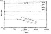
- Figure 2 shows the creep strength at 600°C for inventive alloys 4- 6 in comparison to the creep strengths of comparative alloys 1, 7 and 9.
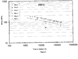
- Figure 3 shows the creep strength at 650°C for inventive alloys 4 -6 in comparison to comparative alloys 1, 8, 9. From figures 1 and 2 it is clear that the inventive alloys, for a given creep stress, shows a longer time to rupture than the comparative alloys.
- Table 2 Creep testing at 600°C Alloy Heat Time to rupture (hours) Stress (MPa) Rupture elongation (%) 1 763554 32621 150 55 2 462269 49738 170 71 3 477353 50986 170 72 4 469837 117561 160 71 5 471988 67644 160 79 6 469718 102321 160 90 7 477217 104958 150 38 8 477203 105889 150 46 9 460335 85940 140 63 10 463024 7629 165 65
- Table 2 shows the time to rupture and the creep strength or applied stress of each alloy at 600°C. Table 2 further shows the rupture elongation i.e. the length increase until rupture expressed as percentage of nominal length for each sample.
- inventive alloys 4 - 6 shows the highest time to rupture when the magnitude of the creep strength i.e. applied stress is taken into consideration. Alloy 4 shows a peak value of 117561 hours at an applied stress of 160 MPa. Alloys 4 -6 further show very high rupture elongation.
- High ductility which is expressed as rupture elongation in tables 2 and 3, is further advantageous when the material is used in steam boilers since it allows for high thermoplastic expansion and contraction of the material during start and shutdown of the boiler.
- the material can be subjected to cyclic heating and cooling without cracking.
- the comparative alloys 1-3, 9 and 10 have comparatively high rupture elongation, see for example comparative alloys 2 and 3 which exhibit a rupture elongation of 71% and 72% respectively. However, theses alloys exhibit a shorter time to rupture, than the inventive alloys. It is believed that the shorter time to rupture in alloys 1-3, 9 and 10 is due to the fact that these alloys contain relatively small amounts of nitrogen. The low nitrogen content results in that fewer carbonitrides are precipitated in these materials than in the inventive alloys. Since alloys 1-3, 9 and 10 comprise few carbonitrides, dislocations can move more easily through these materials. This causes in turn a higher strain rate in the material, i.e. the material deforms faster.
- Comparative alloys 7 and 8 exhibits rather high creep resistance, expressed as longer time to rupture at a given applied stress. However, it should be noted that the longer time to rupture for these alloys was determined at a lower stress, i.e. 150 MPa, than the inventive alloys which were evaluated at a stress of 160 MPa. Hence, the time to rupture of the comparative alloys 7 and 8 is lower than the time to rupture of the inventive alloys 4 and 6. The low time to rupture of alloys 7 and 8 is believed to be caused by brittleness induced by intermetallic phase precipitates. As is shown in table 2, alloys 7 and 8 have a rupture elongation of merely 38% and 46% respectively.
- Table 3 shows the result of creep testing at some applied loads at a temperature of 650°C.
- Table 3 Creep testing at 650°C Alloy Heat Time to rupture (h) Stress (MPa) Rupture elongation (%) 1 763554 32621 95 45 4 469837 116711 95 70 5 471988 106165 95 52 6 469718 95883 105 45 6 469718 188609 95 31 8 477203 32665 120 62 9 460335 44168 105 50
- Table 3 shows that inventive alloys 4 - 6 have better creep properties expressed as time to rupture, creep strength and rupture elongation than the comparative alloys.
- the ductility for all alloys, i.e. the rupture elongation is lower at 650°C in comparison to the ductility at 600°C.
- the reduction in ductility is caused by the fact that more precipitations are formed at higher temperatures and by faster grain growth at higher temperature.
Landscapes
- Chemical & Material Sciences (AREA)
- Engineering & Computer Science (AREA)
- Mechanical Engineering (AREA)
- Metallurgy (AREA)
- Materials Engineering (AREA)
- Organic Chemistry (AREA)
- Physics & Mathematics (AREA)
- Thermal Sciences (AREA)
- General Engineering & Computer Science (AREA)
- Turbine Rotor Nozzle Sealing (AREA)
- Heat Treatment Of Steel (AREA)
- Powder Metallurgy (AREA)
- Production Of Liquid Hydrocarbon Mixture For Refining Petroleum (AREA)
Abstract
Description
- The present invention relates to an austenitic alloy according to the preamble of
claim 1. The invention also relates to a component for a combustion plant comprising the inventive austenitic alloy. - Power generation based on the combustion of biomass is regarded both sustainable and carbon neutral and is becoming an increasingly important source of energy.
- A problem in biomass combustion is that the combustion products of the wide range of biomass fuels that are used are corrosive and may cause depositions on components in the biomass power plant. Especially exposed are superheaters, reheaters and evaporators in biomass power plants, as well as in conventional steam boilers. A further problem in biomass power plants is that the materials in the components start to creep due to the high temperatures and the high pressures in the power plant. Today, biomass plants operate at a pressure of 150-200 bar and at a temperature of 500 - 550°C. In the future, biomass power plants temperatures are expected to be even higher than today, 600 - 650°C. This will put even higher demands on the hot corrosion resistance and the creep strength of the structural parts of the power plant.
- Attempts have been made to increase corrosion resistance in steels. For example
US4876065 andW00190432 - Studies have further shown that austenitic stainless steel with high Mo content shows good resistance to high temperature corrosion: James R.Keisler, Oak ridge National laboratory, NACE Corrosion 2010, No 10081.
- However, these steel do not exhibit the necessary creep strength to be suitable in biomass power plants.
- Therefore, it is an object of the present invention to achieve an austenitic alloy which exhibits high corrosion resistance and high creep strength. It is also an object of the present invention to achieve a component for a steam boiler plant that comprises the inventive alloy.
- According to the invention, this object is achieved by an austenitic alloy comprising (in weight%):
C: 0.01 - 0.05 Si: 0.05 - 0.80 Mn: 1.5 - 2 Cr: 26 - 34.5 Ni: 30 - 35 Mo: 3 - 4 Cu: 0.5 - 1.5 N: 0.05 - 0.15 V: ≤ 0.15 - The inventive austenitic alloy has good resistance to high temperature corrosion, in particular good fire side corrosion. By balancing the additions of nickel and nitrogen in the alloy so that the
condition 40 ≤ %Ni + 100*%N ≤ 50 is fulfilled, a high creep strength and high ductility are further achieved in the alloy. The good resistance to high temperature corrosion in combination with high creep strength makes the inventive austenitic alloy very suitable as a material for structural parts in steam boilers. The inventive alloy is particularly useful in biomass power plants which operate under corrosive conditions at high temperatures and pressures. - Preferably, said austenitic alloy fulfils the requirement: 40 ≤ %Ni + 100*%N ≤ 45. The alloy then exhibits very good creep strength and high ductility. This is advantageous when the material is used in steam boilers since it allows for high thermoplastic expansion and contraction of the material during start and shutdown of the boiler. Thus, the material can be subjected to cyclic heating and cooling without cracking.
- Preferably the content of silica (Si) in the austenitic alloy is 0.3 - 0.55 wt%. Very high creep strength is thereby achieved in the alloy due to minimal formation of brittle sigma phase and minimal formation of oxygen containing inclusions.
- Preferably, the content of carbon (C) in said austenitic alloy is 0.01 - 0.018 wt% in order to optimize the resistance to corrosion.
- The invention also relates to a component for a combustion plant, preferably a biomass power plant or a biomass steam boiler that comprises the inventive austenitic alloy.
- Said component may for example be a superheater or a reheater or an evaporator, preferably a tube of such a superheater, reheater or evaporator, and wherein the component is subjected to flue gases and elevated heat when in its operative position. The invention may thus, as an alternative, be defined as a combustion plant, preferably a biomass power plant, comprising a boiler, preferably a biomass steam boiler, comprising a component, preferably a superheater tube, a reheater tube or an evaporator tube, arranged in the boiler and subjected to flue gases and heat generated by said boiler during operation thereof, wherein said component comprises the alloy according to the invention.
- The inventive austenitic alloy comprises the following alloy elements:
- Carbon is an austenite stabilizing element and should therefore be included in the inventive alloy in an amount of at least 0.01 wt% Carbon is further important for increasing the creep strength of the material by the formation of carbonitrides. However, in the presence of chromium carbon forms chromium carbides which increases the risk of intergranular-corrosion. High carbon contents further reduces weldability. To minimize the formation of chromium carbides and to ensure good weldability the carbon content should not exceed 0.05 wt%. To inhibit the formation of chromium carbides even further, the content of carbon should preferably be in the range of 0.01 - 0.018 wt%.
- Silicon is used as a deoxidising element in the production of steel. However a high content of silicon is detrimental to weldability. In order to ensure low oxygen content in the steel and thereby few inclusions, the content of silicon should be at least 0.05 wt%. The content of silicon should however not exceed 0,80 wt% in order to ensure weldability of the steel. It has been found that when the content of silicon is in the range of 0.30 - 0.55 wt% very high creep strength is achieved in the inventive alloy. It is believed that the formation of sigma phase increases when the silicon level exceeds 0.55 wt%. The sigma phase reduces the ductility of the inventive alloy and therefore also the creep strength. Below 0.30 wt% the creep strength is reduced due to increased formation of oxygen-containing inclusions.
- Manganese, like Si, is a deoxidising element, and it is also effective to improve the hot workability. The maximum content of manganese needs to be limited to control the ductility and toughness of the inventive alloy at room temperature. Therefore, the content of manganese should be in the range of 1.50 - 2.0 wt%.
- Chromium is an effective element to improve the fire side corrosion resistance and steam oxidation resistance. In order to achieve a sufficient hot corrosion resistance for use as e.g. boiler tubes in biomass combustion power plants, a chromium content of at least 26% is needed. However, if the chromium is higher than 34.5%, the nickel content must be further increased since a higher Cr content can increase the risk of formation of intermetallic phases such as sigma phase. The chromium content should therefore be in the interval of 26.0 wt% - 34.5 wt%. In the case of the present invention, very good material properties have been obtained with chromium contents in the range of 26.0-29.0 wt%, which is therefore to be regarded as a preferred range or at least an even more limited range within which the technical effect of the invention is achieved.
- Nickel is an essential element for the purpose of ensuring a stable austenitic structure in the inventive alloy so that the formation of inter-metallic phases like sigma phase is suppressed. Sigma-phase is a hard and brittle intermetallic phase with chromium and molybdenum and is formed at elevated temperatures. Sigma phase has a negative impact of the ductility and elongation of the steel. By stabilizing the austenitic phase in the alloy, the formation of sigma phase is minimized. Nickel is therefore important for ensuring sufficient ductility and elongation of the steel. Nickel has also a positive effect on the corrosion resistance of the inventive alloy since it promotes the formation of a passive Cr-oxide film that suppresses further oxide growth, s c. scaling. The content of nickel should be at least 30 wt% in the inventive alloy in order to ensure structure stability, corrosion resistance and ductility. However, nickel is a relatively expensive alloy element and in order to maintain low production costs the content of nickel should be limited. Nickel further decreases the solubility of nitrogen in the alloy and therefore the content of nickel should not exceed 35 wt%.
- Molybdenum is included in the inventive alloy in order to improve the hot corrosion resistance on the fire side of boiler tubes. Addition of Mo further improves the general-corrosion resistance of the inventive alloy. However, Mo is an expensive element and promotes precipitation of sigma-phase and thus invites deterioration of toughness of the steel. In order to ensure good hot corrosion resistance in the steel the content of molybdenum should be at least 3 wt%. The upper limit of molybdenum is 4 wt% to avoid precipitation of sigma phase.
- Addition of copper can improve both the creep strength by precipitation of copper rich phase, finely and uniformly precipitated in the matrix. However, an excessive amount of copper results in decreased workability. A high amount of copper can also lead to a decrease of ductility and toughness. Therefore the content of copper in the inventive alloy should be in the interval of 0.5 - 1.5 wt%. In the case of the present invention, particularly good results have been obtained with a copper content in the range of 0.8 - 1.2 wt%, which is therefore, at least for that reason, to be regarded as a preferred range or at least a more limited range within which the technical effect of the invention is achieved.
- Nitrogen has a strong stabilizing effect on the austenitic structure and reduces therefore the formation of sigma-phase. This has a positive effect on the ductility of the steel. In the inventive alloy the main effect of nitrogen is that it, together with carbon, forms precipitations in the form of carbonitrides. The small carbonitride particles are generally precipitated at the grain boundaries of the steel and stop dislocations from propagating within the crystal grains of the steel. This greatly increases the creep resistance of the steel. The content of nitrogen should be at least 0.05 wt% in the inventive alloy in order to ensure a stable austenitic structure and that a sufficient amount of carbonitrides are formed. However, if nitrogen is present in high amounts large primary precipitations of nitrides could appear which reduce the ductility and toughness of the inventive alloy. Therefore, the content of nitrogen in the inventive alloy should be limited to 0.15 wt%.
- Addition of vanadium, titanium or niobium contributes to improve the creep rupture strength through the precipitation of MX phase. However, the excessive amount of vanadium can decrease the weldability and hot workability. Vanadium could therefore be allowed in the inventive alloy in an amount of ≤ 0.15 wt%.
- Phosphorus and sulphur are typically included as impurities in the raw materials for the inventive alloy and could cause weld cracking in high amounts. Therefore phosphorus should not exceed 0.035%. Sulphur should not exceed 0.005%.
- In the inventive alloy, the content of nickel and the content of nitrogen should be balanced to fulfil the requirement: 40 ≤ %Ni + 100*%N ≤ 50. It has shown that within this interval very good creep strength and ductility is achieved. It is believed that the good creep strength is the result of a synergistic effect from nickel and nitrogen. Preferably, the content of nickel and the content of nitrogen should be balanced to fulfil the requirement: 40 ≤ %Ni + 100*%N ≤ 45.
- As stated above, nitrogen forms carbonitrides which promotes the creep strength by increasing the creep strain in the alloy. However, creep strength is affected negatively by any brittle phases, such as sigma phase. The addition of both nickel and nitrogen suppresses the formation of sigma-phase in the steel and increases thereby rupture elongation or the ductility of the alloy. This will reduce stress concentration and possible crack initiation and propagation. Consequently, this leads to an increase of the creep strength.
-
-
Figure 1 : A table over alloy compositions -
Figure 2 : A diagram showing results from creep tests at 600°C of inventive alloys and comparative alloys. -
Figure 3 : A diagram showing results from creep tests at 650°C of inventive alloys and comparative alloys. - Following the inventive alloy will be described with reference to a concrete example.
- Ten steel heats were prepared by conventional steel making methods. The composition of respective steel heat is shown in table 1. The conventional metallurgical process according to which the heats were prepared was as follows: Melting by AOD method - hot rolling - extruding - cold pilgring (cold deformation)-solution annealing -water quenching. The hollow bar material after the hot extruding was then cold pilgred with a cold deformation between 40 to 80%, followed by a solution annealing at a temperature between 1050 to 1180°C depending on the dimension. The following table shows the details.
Alloy Heat Cold deformation Annealing Cooling (%) 1 763554 40 - 80 1050-1180 °C/5-25 minutes water quenching 2 462269 40 - 80 1050-1180 °C/5-25 minutes water quenching 3 477353 40 - 80 1050-1180 °C/5-25 minutes water quenching 4 469837 40 - 80 1050-1180 °C/5-25 minutes water quenching 5 471988 40 - 80 1050-1180 °C/5-25 minutes water quenching 6 469718 40 - 80 1050-1180 °C/5-25 minutes water quenching 7 477217 40 - 80 1050-1180 °C/5-25 minutes water quenching 8 477203 40 - 80 1050-1180 °C/5-25 minutes water quenching 9 460335 40 - 80 1050-1180 °C/5-25 minutes water quenching 10 463024 40 - 80 1050-1180 °C/5-25 minutes water quenching -
Alloys 1, 7-9 are comparative samples and contain relatively low concentrations of nitrogen.Alloys requirement 40 ≤ %Ni + 100*%N ≤ 50.Alloys - Test samples of each steel heat were prepared. The samples were subjected to creep testing in order to determine their creep properties. Creep testing was performed at two different temperatures: 600°C and 650°C, by applying a constant stress on each sample and determining the time to rupture and rupture elongation of each sample. Rupture elongation is the length increase until rupture expressed as percentage of nominal length for each sample. The applied stress equals the creep rupture strength of the alloy. The creep rupture strength is defined as the stress which, at a given temperature, will cause a material to rupture in a given time.
- The creep tests were performed according to conventional testing methods and conventional mathematic models were used for extrapolating the results.
-
Figure 2 shows the creep strength at 600°C for inventive alloys 4- 6 in comparison to the creep strengths ofcomparative alloys Figure 3 shows the creep strength at 650°C for inventive alloys 4 -6 in comparison tocomparative alloys figures 1 and2 it is clear that the inventive alloys, for a given creep stress, shows a longer time to rupture than the comparative alloys. - Some other results from the creep testing are shown in tables 2 and 3.
Table 2: Creep testing at 600°C Alloy Heat Time to rupture (hours) Stress (MPa) Rupture elongation (%) 1 763554 32621 150 55 2 462269 49738 170 71 3 477353 50986 170 72 4 469837 117561 160 71 5 471988 67644 160 79 6 469718 102321 160 90 7 477217 104958 150 38 8 477203 105889 150 46 9 460335 85940 140 63 10 463024 7629 165 65 - Table 2 shows the time to rupture and the creep strength or applied stress of each alloy at 600°C. Table 2 further shows the rupture elongation i.e. the length increase until rupture expressed as percentage of nominal length for each sample.
- From the test results it can be concluded that the inventive alloys 4 - 6 shows the highest time to rupture when the magnitude of the creep strength i.e. applied stress is taken into consideration.
Alloy 4 shows a peak value of 117561 hours at an applied stress of 160 MPa. Alloys 4 -6 further show very high rupture elongation. - The high results on time to rupture in alloys 4 -6 are believed to depend on a synergistic effect of addition of both nitrogen and nickel. Addition of nitrogen increases the time to rupture by interstitial solution strengthening and also by precipitation strengthening by the formation of carbonitrides. The dense small carbonitrides that are precipitated in the material effectively block dislocation movement through the grains of the alloy material and hence increase the resistance to deformation. Addition of nickel, and also nitrogen, suppresses the formation of intermetallic phase, such as sigma phase, that affects the ductility negatively and hence improves the ductility of the material. The improved ductility reduces stress concentration, crack initiation and crack propagation. The synergistic effect of these properties results in a very high creep strength.
- High ductility, which is expressed as rupture elongation in tables 2 and 3, is further advantageous when the material is used in steam boilers since it allows for high thermoplastic expansion and contraction of the material during start and shutdown of the boiler. Thus, the material can be subjected to cyclic heating and cooling without cracking.
- The comparative alloys 1-3, 9 and 10 have comparatively high rupture elongation, see for example
comparative alloys -
Comparative alloys comparative alloys inventive alloys alloys alloys - Table 3 shows the result of creep testing at some applied loads at a temperature of 650°C.
Table 3: Creep testing at 650°C Alloy Heat Time to rupture (h) Stress (MPa) Rupture elongation (%) 1 763554 32621 95 45 4 469837 116711 95 70 5 471988 106165 95 52 6 469718 95883 105 45 6 469718 188609 95 31 8 477203 32665 120 62 9 460335 44168 105 50 - Table 3 shows that inventive alloys 4 - 6 have better creep properties expressed as time to rupture, creep strength and rupture elongation than the comparative alloys. The ductility for all alloys, i.e. the rupture elongation is lower at 650°C in comparison to the ductility at 600°C. The reduction in ductility is caused by the fact that more precipitations are formed at higher temperatures and by faster grain growth at higher temperature.
Claims (6)
- Austenitic alloy comprising (in weight%):
C: 0.01 - 0.05 Si: 0.05 - 0.80 Mn: 1.5 - 2 Cr: 26 - 34.5 Ni: 30 - 35 Mo: 3 - 4 Cu: 0.5 - 1.5 N: 0.05 - 0.15 V: ≤ 0.15 - The austenitic alloy according to claim 1, wherein
40 ≤ %Ni + 100*%N ≤ 45 - The austenitic alloy according to any preceding claim, wherein
Si: 0.3 - 0.55 - The austenitic alloy according to any preceding claim, wherein
C: 0.01 - 0.018 - A component for a combustion plant characterized in that said component comprises an austenitic alloy according to any of claims 1 - 4.
- A component for a combustion plant according to claim 5, wherein said component is a superheater or a reheater or an evaporator.
Priority Applications (19)
| Application Number | Priority Date | Filing Date | Title |
|---|---|---|---|
| PL12151566T PL2617858T3 (en) | 2012-01-18 | 2012-01-18 | Austenitic alloy |
| HUE12151566A HUE026095T2 (en) | 2012-01-18 | 2012-01-18 | Austenitic alloy |
| EP12151566.2A EP2617858B1 (en) | 2012-01-18 | 2012-01-18 | Austenitic alloy |
| DK12151566.2T DK2617858T3 (en) | 2012-01-18 | 2012-01-18 | Austenitic alloy |
| ES12151566.2T ES2543046T3 (en) | 2012-01-18 | 2012-01-18 | Austenitic alloy |
| TW102101449A TWI551699B (en) | 2012-01-18 | 2013-01-15 | Austenitic alloy |
| UAA201409161A UA112886C2 (en) | 2012-01-18 | 2013-01-16 | AUSTENITE ALLOY |
| KR1020197038243A KR102094655B1 (en) | 2012-01-18 | 2013-01-16 | Austenitic alloy |
| KR1020147020015A KR20140117417A (en) | 2012-01-18 | 2013-01-16 | Austenitic alloy |
| BR112014017637-0A BR112014017637B1 (en) | 2012-01-18 | 2013-01-16 | AUSTENITIC ALLOY AND COMPONENT FOR A COMBUSTION INSTALLATION |
| PCT/EP2013/050723 WO2013107763A1 (en) | 2012-01-18 | 2013-01-16 | Austenitic alloy |
| CA2863508A CA2863508C (en) | 2012-01-18 | 2013-01-16 | Austenitic alloy |
| US14/372,760 US9587295B2 (en) | 2012-01-18 | 2013-01-16 | Austenitic alloy |
| CN201810378579.3A CN108517453A (en) | 2012-01-18 | 2013-01-16 | Austenitic alloy |
| IN1489KON2014 IN2014KN01489A (en) | 2012-01-18 | 2013-01-16 | |
| JP2014552606A JP6227561B2 (en) | 2012-01-18 | 2013-01-16 | Austenitic alloy |
| MX2014008621A MX337955B (en) | 2012-01-18 | 2013-01-16 | Austenitic alloy. |
| CN201380006041.5A CN104066862A (en) | 2012-01-18 | 2013-01-16 | Austenitic alloy |
| US15/404,397 US10487378B2 (en) | 2012-01-18 | 2017-01-12 | Austenitic alloy |
Applications Claiming Priority (1)
| Application Number | Priority Date | Filing Date | Title |
|---|---|---|---|
| EP12151566.2A EP2617858B1 (en) | 2012-01-18 | 2012-01-18 | Austenitic alloy |
Publications (2)
| Publication Number | Publication Date |
|---|---|
| EP2617858A1 true EP2617858A1 (en) | 2013-07-24 |
| EP2617858B1 EP2617858B1 (en) | 2015-07-15 |
Family
ID=47844258
Family Applications (1)
| Application Number | Title | Priority Date | Filing Date |
|---|---|---|---|
| EP12151566.2A Active EP2617858B1 (en) | 2012-01-18 | 2012-01-18 | Austenitic alloy |
Country Status (15)
| Country | Link |
|---|---|
| US (2) | US9587295B2 (en) |
| EP (1) | EP2617858B1 (en) |
| JP (1) | JP6227561B2 (en) |
| KR (2) | KR20140117417A (en) |
| CN (2) | CN108517453A (en) |
| CA (1) | CA2863508C (en) |
| DK (1) | DK2617858T3 (en) |
| ES (1) | ES2543046T3 (en) |
| HU (1) | HUE026095T2 (en) |
| IN (1) | IN2014KN01489A (en) |
| MX (1) | MX337955B (en) |
| PL (1) | PL2617858T3 (en) |
| TW (1) | TWI551699B (en) |
| UA (1) | UA112886C2 (en) |
| WO (1) | WO2013107763A1 (en) |
Cited By (1)
| Publication number | Priority date | Publication date | Assignee | Title |
|---|---|---|---|---|
| WO2017198831A1 (en) | 2016-05-20 | 2017-11-23 | Sandvik Intellectual Property Ab | An object comprising a pre-oxidized nickel-based alloy |
Families Citing this family (5)
| Publication number | Priority date | Publication date | Assignee | Title |
|---|---|---|---|---|
| ES2543046T3 (en) * | 2012-01-18 | 2015-08-14 | Sandvik Intellectual Property Ab | Austenitic alloy |
| CN105066096A (en) * | 2015-08-05 | 2015-11-18 | 上海锅炉厂有限公司 | Header of ultra supercritical boiler unit at 700 DEG C |
| EP3397406B1 (en) * | 2015-12-30 | 2021-07-07 | Sandvik Intellectual Property AB | A process of producing a duplex stainless steel tube |
| WO2017114849A1 (en) * | 2015-12-30 | 2017-07-06 | Sandvik Intellectual Property Ab | A process of producing an austenitic stainless steel tube |
| JP6941003B2 (en) * | 2017-08-17 | 2021-09-29 | 日本冶金工業株式会社 | Fe-Ni-Cr-Mo alloy and its manufacturing method |
Citations (6)
| Publication number | Priority date | Publication date | Assignee | Title |
|---|---|---|---|---|
| WO1989000209A1 (en) * | 1987-06-29 | 1989-01-12 | Carondelet Foundry Company | Corrosion resistant alloy |
| US4876065A (en) | 1987-05-19 | 1989-10-24 | Vdm Nickel-Technologie Aktiengesellschaft | Corrosion-resisting Fe-Ni-Cr alloy |
| WO2001090432A1 (en) | 2000-05-22 | 2001-11-29 | Sandvik Ab; (Publ) | Austenitic alloy |
| WO2003044239A1 (en) * | 2001-11-22 | 2003-05-30 | Sandvik Ab | Use of a super-austenitic stainless steel |
| US20090291017A1 (en) * | 2007-10-03 | 2009-11-26 | Yohei Otome | HIGH STRENGTH Cr-Ni ALLOY MATERIAL AND SEAMLESS PIPE FOR OIL WELL |
| EP2380998A1 (en) * | 2008-12-18 | 2011-10-26 | Sumitomo Metal Industries, Ltd. | Method for producing high alloy steel pipe |
Family Cites Families (15)
| Publication number | Priority date | Publication date | Assignee | Title |
|---|---|---|---|---|
| US5378427A (en) * | 1991-03-13 | 1995-01-03 | Sumitomo Metal Industries, Ltd. | Corrosion-resistant alloy heat transfer tubes for heat-recovery boilers |
| DE4210997C1 (en) * | 1992-04-02 | 1993-01-14 | Krupp Vdm Gmbh, 5980 Werdohl, De | |
| JP2987732B2 (en) * | 1993-03-25 | 1999-12-06 | 新日本製鐵株式会社 | Method for producing Cr-Ni stainless steel alloy free from surface flaws by hot rolling |
| JP3534886B2 (en) * | 1995-03-24 | 2004-06-07 | 日新製鋼株式会社 | Austenitic stainless steel sheet excellent in pocket wave resistance and method for producing the same |
| KR100361548B1 (en) * | 1999-04-19 | 2002-11-21 | 스미토모 긴조쿠 고교 가부시키가이샤 | Stainless steel product for producing polymer electrode fuel cell |
| JP2005023353A (en) * | 2003-06-30 | 2005-01-27 | Sumitomo Metal Ind Ltd | Austenitic stainless steel for high temperature water environment |
| US7028478B2 (en) * | 2003-12-16 | 2006-04-18 | Advanced Combustion Energy Systems, Inc. | Method and apparatus for the production of energy |
| WO2006003953A1 (en) | 2004-06-30 | 2006-01-12 | Sumitomo Metal Industries, Ltd. | RAW PIPE OF Fe-Ni ALLOY AND METHOD FOR PRODUCTION THEREOF |
| KR100931448B1 (en) * | 2005-04-04 | 2009-12-11 | 수미도모 메탈 인더스트리즈, 리미티드 | Austenitic Stainless Steels |
| DK1997918T3 (en) * | 2006-03-02 | 2019-09-02 | Nippon Steel Corp | Process for producing a steel pipe with excellent vapor resistance oxidation properties |
| WO2008010965A1 (en) * | 2006-07-18 | 2008-01-24 | Exxonmobil Research And Engineering Company | High performance coated material with improved metal dusting corrosion resistance |
| JP2009167502A (en) * | 2008-01-18 | 2009-07-30 | Daido Steel Co Ltd | Austenitic stainless steel for fuel cell separator |
| JP4811529B2 (en) * | 2009-07-23 | 2011-11-09 | Jfeスチール株式会社 | Stainless steel for fuel cells having excellent corrosion resistance and method for producing the same |
| WO2012132992A1 (en) * | 2011-03-28 | 2012-10-04 | 住友金属工業株式会社 | High-strength austenitic stainless steel for high-pressure hydrogen gas |
| ES2543046T3 (en) * | 2012-01-18 | 2015-08-14 | Sandvik Intellectual Property Ab | Austenitic alloy |
-
2012
- 2012-01-18 ES ES12151566.2T patent/ES2543046T3/en active Active
- 2012-01-18 DK DK12151566.2T patent/DK2617858T3/en active
- 2012-01-18 PL PL12151566T patent/PL2617858T3/en unknown
- 2012-01-18 EP EP12151566.2A patent/EP2617858B1/en active Active
- 2012-01-18 HU HUE12151566A patent/HUE026095T2/en unknown
-
2013
- 2013-01-15 TW TW102101449A patent/TWI551699B/en not_active IP Right Cessation
- 2013-01-16 IN IN1489KON2014 patent/IN2014KN01489A/en unknown
- 2013-01-16 CA CA2863508A patent/CA2863508C/en active Active
- 2013-01-16 CN CN201810378579.3A patent/CN108517453A/en active Pending
- 2013-01-16 MX MX2014008621A patent/MX337955B/en active IP Right Grant
- 2013-01-16 UA UAA201409161A patent/UA112886C2/en unknown
- 2013-01-16 CN CN201380006041.5A patent/CN104066862A/en active Pending
- 2013-01-16 WO PCT/EP2013/050723 patent/WO2013107763A1/en not_active Ceased
- 2013-01-16 US US14/372,760 patent/US9587295B2/en active Active
- 2013-01-16 KR KR1020147020015A patent/KR20140117417A/en not_active Ceased
- 2013-01-16 JP JP2014552606A patent/JP6227561B2/en active Active
- 2013-01-16 KR KR1020197038243A patent/KR102094655B1/en not_active Expired - Fee Related
-
2017
- 2017-01-12 US US15/404,397 patent/US10487378B2/en not_active Expired - Fee Related
Patent Citations (6)
| Publication number | Priority date | Publication date | Assignee | Title |
|---|---|---|---|---|
| US4876065A (en) | 1987-05-19 | 1989-10-24 | Vdm Nickel-Technologie Aktiengesellschaft | Corrosion-resisting Fe-Ni-Cr alloy |
| WO1989000209A1 (en) * | 1987-06-29 | 1989-01-12 | Carondelet Foundry Company | Corrosion resistant alloy |
| WO2001090432A1 (en) | 2000-05-22 | 2001-11-29 | Sandvik Ab; (Publ) | Austenitic alloy |
| WO2003044239A1 (en) * | 2001-11-22 | 2003-05-30 | Sandvik Ab | Use of a super-austenitic stainless steel |
| US20090291017A1 (en) * | 2007-10-03 | 2009-11-26 | Yohei Otome | HIGH STRENGTH Cr-Ni ALLOY MATERIAL AND SEAMLESS PIPE FOR OIL WELL |
| EP2380998A1 (en) * | 2008-12-18 | 2011-10-26 | Sumitomo Metal Industries, Ltd. | Method for producing high alloy steel pipe |
Cited By (1)
| Publication number | Priority date | Publication date | Assignee | Title |
|---|---|---|---|---|
| WO2017198831A1 (en) | 2016-05-20 | 2017-11-23 | Sandvik Intellectual Property Ab | An object comprising a pre-oxidized nickel-based alloy |
Also Published As
| Publication number | Publication date |
|---|---|
| US20170121796A1 (en) | 2017-05-04 |
| US9587295B2 (en) | 2017-03-07 |
| MX337955B (en) | 2016-03-29 |
| CN104066862A (en) | 2014-09-24 |
| ES2543046T3 (en) | 2015-08-14 |
| TWI551699B (en) | 2016-10-01 |
| PL2617858T3 (en) | 2015-12-31 |
| WO2013107763A1 (en) | 2013-07-25 |
| US10487378B2 (en) | 2019-11-26 |
| US20140348699A1 (en) | 2014-11-27 |
| CA2863508C (en) | 2021-05-04 |
| UA112886C2 (en) | 2016-11-10 |
| HUE026095T2 (en) | 2016-05-30 |
| IN2014KN01489A (en) | 2015-10-23 |
| MX2014008621A (en) | 2014-08-29 |
| KR102094655B1 (en) | 2020-03-27 |
| CN108517453A (en) | 2018-09-11 |
| CA2863508A1 (en) | 2013-07-25 |
| JP6227561B2 (en) | 2017-11-08 |
| DK2617858T3 (en) | 2015-10-05 |
| EP2617858B1 (en) | 2015-07-15 |
| BR112014017637A8 (en) | 2017-07-11 |
| KR20200003246A (en) | 2020-01-08 |
| JP2015506415A (en) | 2015-03-02 |
| TW201343935A (en) | 2013-11-01 |
| BR112014017637A2 (en) | 2017-06-20 |
| KR20140117417A (en) | 2014-10-07 |
Similar Documents
| Publication | Publication Date | Title |
|---|---|---|
| US10487378B2 (en) | Austenitic alloy | |
| EP2885440B1 (en) | High-chromium heat-resistant steel | |
| US8313589B2 (en) | High-strength low-alloy steel excellent in high-pressure hydrogen environment embrittlement resistance characteristics and method for producing the same | |
| KR20150023935A (en) | Austenitic steel alloy having excellent creep strength and resistance to oxidation and corrosion at elevated use temperatures | |
| EP3269831B1 (en) | High chromium martensitic heat-resistant seamless steel tube or pipe with combined high creep rupture strength and oxidation resistance | |
| JPH07216511A (en) | High chromium austenitic heat resistant alloy with excellent high temperature strength | |
| US7935303B2 (en) | Low alloy steel | |
| JPH01275739A (en) | Low si high strength and heat-resistant steel tube having excellent ductility and toughness | |
| JP2000026940A (en) | High Cr ferritic heat resistant steel | |
| EP2915893A1 (en) | Austenitic stainless steel | |
| JP2017088957A (en) | Austenitic heat resistant steel | |
| US11339461B2 (en) | Austenitic stainless steel | |
| JPH06322489A (en) | Steel tube for boiler excellent in steam oxidation resistance | |
| JPH0570694B2 (en) | ||
| KR20210137184A (en) | Ferritic heat-resistant steel | |
| JP7709074B2 (en) | Ferritic heat-resistant steel | |
| JPH0288716A (en) | Manufacture of heat resistant high cr ferritic steel pipe having high creep breaking strength | |
| WO2025165286A1 (en) | Use of an austenitic stainless alloy | |
| RU2716922C1 (en) | Austenitic corrosion-resistant steel with nitrogen | |
| KR20150087172A (en) | Duplex stainless steel | |
| JP4878511B2 (en) | MX type carbonitride precipitation strengthened heat resistant steel | |
| KR20000025972A (en) | Heat resistant steel 15cr26ni1.25mo for 650°c class steam turbine rotor |
Legal Events
| Date | Code | Title | Description |
|---|---|---|---|
| PUAI | Public reference made under article 153(3) epc to a published international application that has entered the european phase |
Free format text: ORIGINAL CODE: 0009012 |
|
| 17P | Request for examination filed |
Effective date: 20120118 |
|
| AK | Designated contracting states |
Kind code of ref document: A1 Designated state(s): AL AT BE BG CH CY CZ DE DK EE ES FI FR GB GR HR HU IE IS IT LI LT LU LV MC MK MT NL NO PL PT RO RS SE SI SK SM TR |
|
| AX | Request for extension of the european patent |
Extension state: BA ME |
|
| RBV | Designated contracting states (corrected) |
Designated state(s): AL AT BE BG CH CY CZ DE DK EE ES FI FR GB GR HR HU IE IS IT LI LT LU LV MC MK MT NL NO PL PT RO RS SE SI SK SM TR |
|
| GRAP | Despatch of communication of intention to grant a patent |
Free format text: ORIGINAL CODE: EPIDOSNIGR1 |
|
| GRAC | Information related to communication of intention to grant a patent modified |
Free format text: ORIGINAL CODE: EPIDOSCIGR1 |
|
| INTG | Intention to grant announced |
Effective date: 20150302 |
|
| INTG | Intention to grant announced |
Effective date: 20150309 |
|
| GRAS | Grant fee paid |
Free format text: ORIGINAL CODE: EPIDOSNIGR3 |
|
| GRAA | (expected) grant |
Free format text: ORIGINAL CODE: 0009210 |
|
| AK | Designated contracting states |
Kind code of ref document: B1 Designated state(s): AL AT BE BG CH CY CZ DE DK EE ES FI FR GB GR HR HU IE IS IT LI LT LU LV MC MK MT NL NO PL PT RO RS SE SI SK SM TR |
|
| REG | Reference to a national code |
Ref country code: CH Ref legal event code: EP Ref country code: GB Ref legal event code: FG4D |
|
| REG | Reference to a national code |
Ref country code: CH Ref legal event code: NV Representative=s name: BOVARD AG, CH |
|
| REG | Reference to a national code |
Ref country code: IE Ref legal event code: FG4D |
|
| REG | Reference to a national code |
Ref country code: ES Ref legal event code: FG2A Ref document number: 2543046 Country of ref document: ES Kind code of ref document: T3 Effective date: 20150814 |
|
| REG | Reference to a national code |
Ref country code: AT Ref legal event code: REF Ref document number: 736846 Country of ref document: AT Kind code of ref document: T Effective date: 20150815 |
|
| REG | Reference to a national code |
Ref country code: DE Ref legal event code: R096 Ref document number: 602012008731 Country of ref document: DE |
|
| REG | Reference to a national code |
Ref country code: SE Ref legal event code: TRGR |
|
| REG | Reference to a national code |
Ref country code: DK Ref legal event code: T3 Effective date: 20150928 |
|
| REG | Reference to a national code |
Ref country code: NO Ref legal event code: T2 Effective date: 20150715 |
|
| REG | Reference to a national code |
Ref country code: FR Ref legal event code: PLFP Year of fee payment: 5 |
|
| REG | Reference to a national code |
Ref country code: NL Ref legal event code: FP |
|
| REG | Reference to a national code |
Ref country code: LT Ref legal event code: MG4D |
|
| REG | Reference to a national code |
Ref country code: PL Ref legal event code: T3 |
|
| REG | Reference to a national code |
Ref country code: SK Ref legal event code: T3 Ref document number: E 19345 Country of ref document: SK |
|
| PG25 | Lapsed in a contracting state [announced via postgrant information from national office to epo] |
Ref country code: LV Free format text: LAPSE BECAUSE OF FAILURE TO SUBMIT A TRANSLATION OF THE DESCRIPTION OR TO PAY THE FEE WITHIN THE PRESCRIBED TIME-LIMIT Effective date: 20150715 Ref country code: LT Free format text: LAPSE BECAUSE OF FAILURE TO SUBMIT A TRANSLATION OF THE DESCRIPTION OR TO PAY THE FEE WITHIN THE PRESCRIBED TIME-LIMIT Effective date: 20150715 Ref country code: GR Free format text: LAPSE BECAUSE OF FAILURE TO SUBMIT A TRANSLATION OF THE DESCRIPTION OR TO PAY THE FEE WITHIN THE PRESCRIBED TIME-LIMIT Effective date: 20151016 |
|
| PG25 | Lapsed in a contracting state [announced via postgrant information from national office to epo] |
Ref country code: HR Free format text: LAPSE BECAUSE OF FAILURE TO SUBMIT A TRANSLATION OF THE DESCRIPTION OR TO PAY THE FEE WITHIN THE PRESCRIBED TIME-LIMIT Effective date: 20150715 Ref country code: PT Free format text: LAPSE BECAUSE OF FAILURE TO SUBMIT A TRANSLATION OF THE DESCRIPTION OR TO PAY THE FEE WITHIN THE PRESCRIBED TIME-LIMIT Effective date: 20151116 Ref country code: RS Free format text: LAPSE BECAUSE OF FAILURE TO SUBMIT A TRANSLATION OF THE DESCRIPTION OR TO PAY THE FEE WITHIN THE PRESCRIBED TIME-LIMIT Effective date: 20150715 |
|
| REG | Reference to a national code |
Ref country code: DE Ref legal event code: R097 Ref document number: 602012008731 Country of ref document: DE |
|
| PG25 | Lapsed in a contracting state [announced via postgrant information from national office to epo] |
Ref country code: EE Free format text: LAPSE BECAUSE OF FAILURE TO SUBMIT A TRANSLATION OF THE DESCRIPTION OR TO PAY THE FEE WITHIN THE PRESCRIBED TIME-LIMIT Effective date: 20150715 |
|
| PLBE | No opposition filed within time limit |
Free format text: ORIGINAL CODE: 0009261 |
|
| STAA | Information on the status of an ep patent application or granted ep patent |
Free format text: STATUS: NO OPPOSITION FILED WITHIN TIME LIMIT |
|
| REG | Reference to a national code |
Ref country code: HU Ref legal event code: AG4A Ref document number: E026095 Country of ref document: HU |
|
| PG25 | Lapsed in a contracting state [announced via postgrant information from national office to epo] |
Ref country code: RO Free format text: LAPSE BECAUSE OF FAILURE TO SUBMIT A TRANSLATION OF THE DESCRIPTION OR TO PAY THE FEE WITHIN THE PRESCRIBED TIME-LIMIT Effective date: 20150715 |
|
| 26N | No opposition filed |
Effective date: 20160418 |
|
| PG25 | Lapsed in a contracting state [announced via postgrant information from national office to epo] |
Ref country code: IS Free format text: LAPSE BECAUSE OF FAILURE TO SUBMIT A TRANSLATION OF THE DESCRIPTION OR TO PAY THE FEE WITHIN THE PRESCRIBED TIME-LIMIT Effective date: 20150715 |
|
| PG25 | Lapsed in a contracting state [announced via postgrant information from national office to epo] |
Ref country code: LU Free format text: LAPSE BECAUSE OF FAILURE TO SUBMIT A TRANSLATION OF THE DESCRIPTION OR TO PAY THE FEE WITHIN THE PRESCRIBED TIME-LIMIT Effective date: 20160118 Ref country code: SI Free format text: LAPSE BECAUSE OF FAILURE TO SUBMIT A TRANSLATION OF THE DESCRIPTION OR TO PAY THE FEE WITHIN THE PRESCRIBED TIME-LIMIT Effective date: 20150715 |
|
| PG25 | Lapsed in a contracting state [announced via postgrant information from national office to epo] |
Ref country code: MC Free format text: LAPSE BECAUSE OF FAILURE TO SUBMIT A TRANSLATION OF THE DESCRIPTION OR TO PAY THE FEE WITHIN THE PRESCRIBED TIME-LIMIT Effective date: 20150715 |
|
| REG | Reference to a national code |
Ref country code: IE Ref legal event code: MM4A |
|
| REG | Reference to a national code |
Ref country code: FR Ref legal event code: PLFP Year of fee payment: 6 |
|
| PG25 | Lapsed in a contracting state [announced via postgrant information from national office to epo] |
Ref country code: IE Free format text: LAPSE BECAUSE OF NON-PAYMENT OF DUE FEES Effective date: 20160118 |
|
| REG | Reference to a national code |
Ref country code: AT Ref legal event code: UEP Ref document number: 736846 Country of ref document: AT Kind code of ref document: T Effective date: 20150715 |
|
| PG25 | Lapsed in a contracting state [announced via postgrant information from national office to epo] |
Ref country code: MT Free format text: LAPSE BECAUSE OF FAILURE TO SUBMIT A TRANSLATION OF THE DESCRIPTION OR TO PAY THE FEE WITHIN THE PRESCRIBED TIME-LIMIT Effective date: 20150715 |
|
| REG | Reference to a national code |
Ref country code: FR Ref legal event code: PLFP Year of fee payment: 7 |
|
| PG25 | Lapsed in a contracting state [announced via postgrant information from national office to epo] |
Ref country code: SM Free format text: LAPSE BECAUSE OF FAILURE TO SUBMIT A TRANSLATION OF THE DESCRIPTION OR TO PAY THE FEE WITHIN THE PRESCRIBED TIME-LIMIT Effective date: 20150715 Ref country code: CY Free format text: LAPSE BECAUSE OF FAILURE TO SUBMIT A TRANSLATION OF THE DESCRIPTION OR TO PAY THE FEE WITHIN THE PRESCRIBED TIME-LIMIT Effective date: 20150715 |
|
| PG25 | Lapsed in a contracting state [announced via postgrant information from national office to epo] |
Ref country code: MT Free format text: LAPSE BECAUSE OF FAILURE TO SUBMIT A TRANSLATION OF THE DESCRIPTION OR TO PAY THE FEE WITHIN THE PRESCRIBED TIME-LIMIT Effective date: 20160131 Ref country code: MK Free format text: LAPSE BECAUSE OF FAILURE TO SUBMIT A TRANSLATION OF THE DESCRIPTION OR TO PAY THE FEE WITHIN THE PRESCRIBED TIME-LIMIT Effective date: 20150715 |
|
| PG25 | Lapsed in a contracting state [announced via postgrant information from national office to epo] |
Ref country code: BG Free format text: LAPSE BECAUSE OF FAILURE TO SUBMIT A TRANSLATION OF THE DESCRIPTION OR TO PAY THE FEE WITHIN THE PRESCRIBED TIME-LIMIT Effective date: 20150715 |
|
| PG25 | Lapsed in a contracting state [announced via postgrant information from national office to epo] |
Ref country code: AL Free format text: LAPSE BECAUSE OF FAILURE TO SUBMIT A TRANSLATION OF THE DESCRIPTION OR TO PAY THE FEE WITHIN THE PRESCRIBED TIME-LIMIT Effective date: 20150715 |
|
| PGFP | Annual fee paid to national office [announced via postgrant information from national office to epo] |
Ref country code: SK Payment date: 20201215 Year of fee payment: 10 Ref country code: BE Payment date: 20201216 Year of fee payment: 10 |
|
| PGFP | Annual fee paid to national office [announced via postgrant information from national office to epo] |
Ref country code: CH Payment date: 20210113 Year of fee payment: 10 |
|
| PGFP | Annual fee paid to national office [announced via postgrant information from national office to epo] |
Ref country code: HU Payment date: 20201212 Year of fee payment: 10 Ref country code: TR Payment date: 20210114 Year of fee payment: 10 |
|
| PGFP | Annual fee paid to national office [announced via postgrant information from national office to epo] |
Ref country code: FR Payment date: 20211224 Year of fee payment: 11 |
|
| PGFP | Annual fee paid to national office [announced via postgrant information from national office to epo] |
Ref country code: PL Payment date: 20211217 Year of fee payment: 11 Ref country code: NL Payment date: 20211216 Year of fee payment: 11 |
|
| PGFP | Annual fee paid to national office [announced via postgrant information from national office to epo] |
Ref country code: AT Payment date: 20211229 Year of fee payment: 11 |
|
| PGFP | Annual fee paid to national office [announced via postgrant information from national office to epo] |
Ref country code: NO Payment date: 20220111 Year of fee payment: 11 Ref country code: IT Payment date: 20211213 Year of fee payment: 11 |
|
| REG | Reference to a national code |
Ref country code: CH Ref legal event code: PL |
|
| REG | Reference to a national code |
Ref country code: SK Ref legal event code: MM4A Ref document number: E 19345 Country of ref document: SK Effective date: 20220118 |
|
| REG | Reference to a national code |
Ref country code: BE Ref legal event code: MM Effective date: 20220131 |
|
| PG25 | Lapsed in a contracting state [announced via postgrant information from national office to epo] |
Ref country code: SK Free format text: LAPSE BECAUSE OF NON-PAYMENT OF DUE FEES Effective date: 20220118 |
|
| PG25 | Lapsed in a contracting state [announced via postgrant information from national office to epo] |
Ref country code: HU Free format text: LAPSE BECAUSE OF NON-PAYMENT OF DUE FEES Effective date: 20220119 Ref country code: BE Free format text: LAPSE BECAUSE OF NON-PAYMENT OF DUE FEES Effective date: 20220131 |
|
| PG25 | Lapsed in a contracting state [announced via postgrant information from national office to epo] |
Ref country code: LI Free format text: LAPSE BECAUSE OF NON-PAYMENT OF DUE FEES Effective date: 20220131 Ref country code: CH Free format text: LAPSE BECAUSE OF NON-PAYMENT OF DUE FEES Effective date: 20220131 |
|
| PGFP | Annual fee paid to national office [announced via postgrant information from national office to epo] |
Ref country code: DK Payment date: 20230111 Year of fee payment: 12 |
|
| P01 | Opt-out of the competence of the unified patent court (upc) registered |
Effective date: 20230526 |
|
| REG | Reference to a national code |
Ref country code: NO Ref legal event code: MMEP |
|
| REG | Reference to a national code |
Ref country code: NL Ref legal event code: MM Effective date: 20230201 |
|
| REG | Reference to a national code |
Ref country code: AT Ref legal event code: MM01 Ref document number: 736846 Country of ref document: AT Kind code of ref document: T Effective date: 20230118 |
|
| PG25 | Lapsed in a contracting state [announced via postgrant information from national office to epo] |
Ref country code: NO Free format text: LAPSE BECAUSE OF NON-PAYMENT OF DUE FEES Effective date: 20230131 Ref country code: NL Free format text: LAPSE BECAUSE OF NON-PAYMENT OF DUE FEES Effective date: 20230201 Ref country code: AT Free format text: LAPSE BECAUSE OF NON-PAYMENT OF DUE FEES Effective date: 20230118 |
|
| REG | Reference to a national code |
Ref country code: GB Ref legal event code: 732E Free format text: REGISTERED BETWEEN 20231026 AND 20231101 |
|
| PG25 | Lapsed in a contracting state [announced via postgrant information from national office to epo] |
Ref country code: FR Free format text: LAPSE BECAUSE OF NON-PAYMENT OF DUE FEES Effective date: 20230131 |
|
| REG | Reference to a national code |
Ref country code: DE Ref legal event code: R081 Ref document number: 602012008731 Country of ref document: DE Owner name: ALLEIMA TUBE AB, SE Free format text: FORMER OWNER: SANDVIK INTELLECTUAL PROPERTY AB, SANDVIKEN, SE |
|
| PG25 | Lapsed in a contracting state [announced via postgrant information from national office to epo] |
Ref country code: IT Free format text: LAPSE BECAUSE OF NON-PAYMENT OF DUE FEES Effective date: 20230118 |
|
| PGFP | Annual fee paid to national office [announced via postgrant information from national office to epo] |
Ref country code: FI Payment date: 20231218 Year of fee payment: 13 |
|
| PG25 | Lapsed in a contracting state [announced via postgrant information from national office to epo] |
Ref country code: PL Free format text: LAPSE BECAUSE OF NON-PAYMENT OF DUE FEES Effective date: 20230118 |
|
| REG | Reference to a national code |
Ref country code: DK Ref legal event code: EBP Effective date: 20240131 |
|
| PG25 | Lapsed in a contracting state [announced via postgrant information from national office to epo] |
Ref country code: TR Free format text: LAPSE BECAUSE OF NON-PAYMENT OF DUE FEES Effective date: 20220118 |
|
| REG | Reference to a national code |
Ref country code: ES Ref legal event code: PC2A Owner name: ALLEIMA TUBE AB Effective date: 20240927 |
|
| PG25 | Lapsed in a contracting state [announced via postgrant information from national office to epo] |
Ref country code: DK Free format text: LAPSE BECAUSE OF NON-PAYMENT OF DUE FEES Effective date: 20240131 |
|
| PGFP | Annual fee paid to national office [announced via postgrant information from national office to epo] |
Ref country code: CZ Payment date: 20241227 Year of fee payment: 14 |
|
| PG25 | Lapsed in a contracting state [announced via postgrant information from national office to epo] |
Ref country code: DK Free format text: LAPSE BECAUSE OF NON-PAYMENT OF DUE FEES Effective date: 20240131 |
|
| PG25 | Lapsed in a contracting state [announced via postgrant information from national office to epo] |
Ref country code: FI Free format text: LAPSE BECAUSE OF NON-PAYMENT OF DUE FEES Effective date: 20250118 |
|
| PGFP | Annual fee paid to national office [announced via postgrant information from national office to epo] |
Ref country code: GB Payment date: 20251204 Year of fee payment: 15 |
|
| PGFP | Annual fee paid to national office [announced via postgrant information from national office to epo] |
Ref country code: SE Payment date: 20251210 Year of fee payment: 15 |
|
| PGFP | Annual fee paid to national office [announced via postgrant information from national office to epo] |
Ref country code: ES Payment date: 20260206 Year of fee payment: 15 |
|
| PGFP | Annual fee paid to national office [announced via postgrant information from national office to epo] |
Ref country code: DE Payment date: 20251203 Year of fee payment: 15 |