EP2617708A1 - A method of forming urea by integration of an ammonia production process in a urea production process and a system therefor - Google Patents
A method of forming urea by integration of an ammonia production process in a urea production process and a system therefor Download PDFInfo
- Publication number
- EP2617708A1 EP2617708A1 EP12151354.3A EP12151354A EP2617708A1 EP 2617708 A1 EP2617708 A1 EP 2617708A1 EP 12151354 A EP12151354 A EP 12151354A EP 2617708 A1 EP2617708 A1 EP 2617708A1
- Authority
- EP
- European Patent Office
- Prior art keywords
- stream
- ammonia
- carbon dioxide
- urea
- conduit
- Prior art date
- Legal status (The legal status is an assumption and is not a legal conclusion. Google has not performed a legal analysis and makes no representation as to the accuracy of the status listed.)
- Granted
Links
Images
Classifications
-
- C—CHEMISTRY; METALLURGY
- C07—ORGANIC CHEMISTRY
- C07C—ACYCLIC OR CARBOCYCLIC COMPOUNDS
- C07C273/00—Preparation of urea or its derivatives, i.e. compounds containing any of the groups, the nitrogen atoms not being part of nitro or nitroso groups
- C07C273/02—Preparation of urea or its derivatives, i.e. compounds containing any of the groups, the nitrogen atoms not being part of nitro or nitroso groups of urea, its salts, complexes or addition compounds
- C07C273/04—Preparation of urea or its derivatives, i.e. compounds containing any of the groups, the nitrogen atoms not being part of nitro or nitroso groups of urea, its salts, complexes or addition compounds from carbon dioxide and ammonia
-
- C—CHEMISTRY; METALLURGY
- C01—INORGANIC CHEMISTRY
- C01C—AMMONIA; CYANOGEN; COMPOUNDS THEREOF
- C01C1/00—Ammonia; Compounds thereof
- C01C1/02—Preparation, purification or separation of ammonia
- C01C1/04—Preparation of ammonia by synthesis
- C01C1/0405—Preparation of ammonia by synthesis from N2 and H2 in presence of a catalyst
- C01C1/0488—Processes integrated with preparations of other compounds, e.g. methanol, urea or with processes for power generation
-
- C—CHEMISTRY; METALLURGY
- C07—ORGANIC CHEMISTRY
- C07C—ACYCLIC OR CARBOCYCLIC COMPOUNDS
- C07C273/00—Preparation of urea or its derivatives, i.e. compounds containing any of the groups, the nitrogen atoms not being part of nitro or nitroso groups
- C07C273/02—Preparation of urea or its derivatives, i.e. compounds containing any of the groups, the nitrogen atoms not being part of nitro or nitroso groups of urea, its salts, complexes or addition compounds
- C07C273/14—Separation; Purification; Stabilisation; Use of additives
- C07C273/16—Separation; Purification
-
- C—CHEMISTRY; METALLURGY
- C10—PETROLEUM, GAS OR COKE INDUSTRIES; TECHNICAL GASES CONTAINING CARBON MONOXIDE; FUELS; LUBRICANTS; PEAT
- C10K—PURIFYING OR MODIFYING THE CHEMICAL COMPOSITION OF COMBUSTIBLE GASES CONTAINING CARBON MONOXIDE
- C10K1/00—Purifying combustible gases containing carbon monoxide
- C10K1/002—Removal of contaminants
- C10K1/003—Removal of contaminants of acid contaminants, e.g. acid gas removal
- C10K1/005—Carbon dioxide
-
- B—PERFORMING OPERATIONS; TRANSPORTING
- B01—PHYSICAL OR CHEMICAL PROCESSES OR APPARATUS IN GENERAL
- B01J—CHEMICAL OR PHYSICAL PROCESSES, e.g. CATALYSIS OR COLLOID CHEMISTRY; THEIR RELEVANT APPARATUS
- B01J2219/00—Chemical, physical or physico-chemical processes in general; Their relevant apparatus
- B01J2219/00002—Chemical plants
- B01J2219/00004—Scale aspects
- B01J2219/00006—Large-scale industrial plants
-
- C—CHEMISTRY; METALLURGY
- C10—PETROLEUM, GAS OR COKE INDUSTRIES; TECHNICAL GASES CONTAINING CARBON MONOXIDE; FUELS; LUBRICANTS; PEAT
- C10J—PRODUCTION OF PRODUCER GAS, WATER-GAS, SYNTHESIS GAS FROM SOLID CARBONACEOUS MATERIAL, OR MIXTURES CONTAINING THESE GASES; CARBURETTING AIR OR OTHER GASES
- C10J2300/00—Details of gasification processes
- C10J2300/16—Integration of gasification processes with another plant or parts within the plant
- C10J2300/164—Integration of gasification processes with another plant or parts within the plant with conversion of synthesis gas
- C10J2300/1656—Conversion of synthesis gas to chemicals
- C10J2300/1668—Conversion of synthesis gas to chemicals to urea; to ammonia
-
- Y—GENERAL TAGGING OF NEW TECHNOLOGICAL DEVELOPMENTS; GENERAL TAGGING OF CROSS-SECTIONAL TECHNOLOGIES SPANNING OVER SEVERAL SECTIONS OF THE IPC; TECHNICAL SUBJECTS COVERED BY FORMER USPC CROSS-REFERENCE ART COLLECTIONS [XRACs] AND DIGESTS
- Y02—TECHNOLOGIES OR APPLICATIONS FOR MITIGATION OR ADAPTATION AGAINST CLIMATE CHANGE
- Y02P—CLIMATE CHANGE MITIGATION TECHNOLOGIES IN THE PRODUCTION OR PROCESSING OF GOODS
- Y02P20/00—Technologies relating to chemical industry
- Y02P20/50—Improvements relating to the production of bulk chemicals
- Y02P20/52—Improvements relating to the production of bulk chemicals using catalysts, e.g. selective catalysts
Definitions
- the present invention relates to a method of forming urea by integration of an ammonia production process in a urea production process, and to a system for said method. It also relates to a method of forming urea by integration of a part of an ammonia production process in a urea production process, and to a system for said method.
- a flue gas containing, inter alia, carbon dioxide is formed.
- This carbon dioxide component is often separated out or captured from the flue gas in one or more absorber systems using a solvent absorber.
- the spent carbon dioxide solvent absorber is then regenerated in one or more regeneration columns.
- carbon dioxide capture systems of this kind there is a need to reduce system energy consumption and capital expenditure (“capex”) requirements.
- capex system energy consumption and capital expenditure
- Solvents typically used in solvent-based carbon dioxide capture systems include amines and ammonia.
- a solvent-based carbon dioxide capture system known as the Chilled Ammonium Process (CAP) is normally used.
- CAP Chilled Ammonium Process
- ammonia is used as the solvent.
- Other processes including a solvent-based carbon dioxide capture system use different kinds of amines or mixtures thereof.
- WO 2006/022885 discloses ultra cleaning of combustion gas including removal of carbon dioxide in an absorbing subsystem with one or more carbon dioxide absorbing stages and a subsequent regeneration subsystem.
- urea, carbamate, water and excess ammonia are transported to a distillation reactor from which a solution or slurry of, inter alia, carbamate in equlibrum with ammonia, carbon dioxide and water is recycled back to the urea synthesis reactor for further reaction.
- WO 2008/135150 discloses a method for purifying flue gases from incinerators and then producing urea.
- ammonia and flue gas containing carbon dioxide is added to a washing device in which carbon dioxide is absorbed.
- a solution containing (NH 4 ) 2 CO 3 and (NH 4 ) 2 SO 4 is emitted from the washing unit and transported to a stripper in which (NH 4 ) 2 SO 4 is separated and (NH 4 ) 2 CO 3 is subjected to an energy-consuming decomposition to carbon dioxide and ammonia. This carbon dioxide and ammonia is then used in a urea production process.
- An object of the present invention is to provide a solvent-based carbon dioxide capture system and method with reduced energy consumption demands and capital cost requirements. This object is achieved by means of a system and method of forming urea by integration of an ammonia production process in a urea production process. As a result of this integration, ammonia and carbon dioxide obtained from synthetic gas (“syngas”) is formed during steam reforming or gasification in connection with the ammonia production process in an ammonia production plant.
- synthetic gas synthetic gas
- a first ammonia stream, a carbon dioxide stream, and a flue gas stream containing carbon dioxide are formed.
- the first ammonia stream is separated into a second ammonia stream for transport to an absorber, and a third ammonia stream for transport to a urea synthesis reactor in a urea production plant.
- the carbon dioxide stream is also transported to the urea synthesis reactor, and the flue gas stream is transported to the absorber for carbon dioxide absorption into a mixed stream comprising the second ammonia stream and a lean solvent stream containing ammonia and a relatively low content of carbon dioxide.
- a rich solvent stream containing ammonia and a relatively high content of carbon dioxide is emitted from the absorber and transported to the urea synthesis reactor.
- carbon dioxide and ammonia are reacted for the production of urea.
- This production of urea produces a relatively lean solvent stream containing ammonia and a relatively low concentration of carbon dioxide for recycling from the urea production plant to the absorber.
- An advantage of this method is that carbon dioxide desorption is unnecessary, since the carbon dioxide in the solvent stream is bound to ammonia, i.e., two reactants necessary for the urea production process. Thereby, by using the carbon dioxide bound ammonia in a urea production process rather than by using the carbon dioxide bound ammonia following desorption, system energy demands and capital expenses are substantially reduced.
- flue gas is obtained from combustion in an ammonia production plant.
- combustion in an ammonia production plant is performed in a steam reformer.
- a flue gas stream is cooled to a temperature of 0-25°C, preferably to a temperature of 10-20°C, before transport to an absorber.
- the absorber is a CAP (Chilled Ammonia Process) absorber.
- a clean gas stream is emitted from an absorber.
- the concentration of ammonia in a mixed stream and in a rich solvent stream is 2-12 moles per liter solution, preferably 6-10 moles per liter solution, wherein the concentration of carbon dioxide in a lean solvent stream is 0.2-4.0 moles per liter solution, preferably 1.5-4 moles per liter solution, and wherein the concentration of carbon dioxide in the rich solvent stream is 1.0- 10.0 moles per liter solution, preferably 3-6.0 moles per liter solution.
- the ratio of the concentration of ammonia to the concentration of carbon dioxide in the lean solvent stream and the rich solvent stream is 1:-1 to 3:1, preferably 3:2 to 5:2.
- the object of the present invention may likewise be achieved by means of an alternative method of forming urea, i.e., by integration of a part of an ammonia production process with that of a urea production process.
- a flue gas containing carbon dioxide and nitrogen from combustion is transported to a low pressure absorber and a hydrogen/carbon dioxide gas mixture from reforming steam is transported to a high pressure absorber.
- the high pressure absorber contains a solvent stream semi-rich with absorbed carbon dioxide. After contact with the hydrogen/carbon dioxide gas mixture, a solvent stream with ammonia and a rich or high content of carbon dioxide is emitted from the high pressure absorber and transported to a urea production plant.
- a syngas stream containing hydrogen and carbon monooxide formed during the steam reforming reaction of the ammonia production process is transported to a carbon monooxide shift unit in which the carbon monooxide is converted into carbon dioxide to form the hydrogen/carbon dioxide stream.
- a nitrogen containing stream is emitted from the urea production process low pressure absorber, and a hydrogen stream is emitted from the urea production process high pressure absorber. Both the nitrogen containing stream and the hydrogen stream are transported to the ammonia production unit and reacted for the production of ammonia.
- an ammonia stream is added to the recycle stream used to generate a lean solvent stream containing ammonia and a relatively low content of carbon dioxide.
- a slip stream diverted from the relatively rich solvent stream is transported to the low pressure absorber.
- a partial stream of the relatively lean solvent stream is added to the high pressure absorber or to the semi rich solvent stream.
- a partial stream of the semi rich solvent stream is transported to the urea production plant.
- the pressure in the low pressure absorber is 0.08-0.15 MPa, preferably 0.095-0.11 MPa, and the pressure in the high pressure absorber is 0.3-4.0 MPa, preferably 0.095-0.11 MPa.
- the concentration of ammonia in the relatively lean solvent stream, in the semi rich solvent stream and in the relatively rich solvent stream is 2-12, preferably 6-9, moles per liter solution.
- the concentration of carbon dioxide in the relatively lean solvent stream is 0.2-4.0, preferably 1.5-4.0, moles per liter solution
- the concentration of carbon dioxide in the semi rich solvent stream is 1.0-5.5, preferably 2.5-4.5, moles per liter of solution
- the concentration of carbon dioxide in the relatively rich solvent stream is 1.0-10.0, preferably 3.0-6.0, moles per liter solution.
- the ratio between the concentration of ammonia and the concentration of carbon dioxide in the lean, semi rich, and rich solvent streams, respectively, is 1:3, preferably 1.5:2.5.
- a further object of the present invention is to provide systems in which the integrated method and the alternative integrated method are performed.
- a system for the integrated method of forming urea by integration of an ammonia production process with that of a urea production process wherein said system comprises an ammonia production plant, an absorber, and a urea synthesis reactor in a urea production plant.
- Said system includes a conduit for a first ammonia stream from the ammonia production plant separated into a conduit for a second ammonia stream fluidly connected to the absorber, or to a conduit for a lean solvent stream thus forming a mixed stream, and into a conduit for a third ammonia stream fluidly connected to the urea synthesis reactor.
- a conduit for a flue gas stream containing carbon dioxide is fluidly connected between the ammonia production plant, or another flue gas source, and the absorber.
- a conduit for a carbon dioxide stream is fluidly connected between the ammonia production plant and the urea synthesis reactor.
- a conduit for a rich solvent stream is fluidly connected between the absorber and the urea synthesis reactor, and a conduit for a lean solvent stream is arranged between the urea production plant and the absorber.
- this system comprises a conduit for a clean gas stream fluidly connected to the absorber.
- Such a system comprises a steam reformer or a gasification reactor of an ammonia production plant, a low pressure absorber, a high pressure absorber, and a urea production plant, wherein a conduit for a flue gas stream is fluidly connected between the steam reformer, or the gasification reactor, and the low pressure absorber.
- a conduit for a hydrogen/carbon dioxide stream is arranged between the steam reformer, the gasification reactor, or another flue gas source, and the high pressure absorber.
- a conduit for a semi rich solvent stream is fluidly connected between the low pressure absorber and the high pressure absorber.
- a conduit for a rich solvent stream is fluidly connected between the high pressure absorber and the urea production plant, and a conduit for a lean solvent stream is fluidly connected between the urea production plant and the low pressure absorber.
- the system comprises an ammonia production unit, a conduit for a hydrogen stream fluidly connected between the high pressure absorber and the ammonia production unit, and a conduit for a nitrogen containing stream fluidly connected between the low pressure absorber and the ammonia production unit.
- the system also comprises a conduit for a stream of the balance of ammonia fluidly connected between the ammonia production unit and the urea production plant.
- the system comprises a carbon monooxide shift unit for the conversion of carbon monooxide into carbon dioxide, wherein a conduit for a syngas stream containing hydrogen and carbon monooxide is fluidly connected between the steam reformer, or the gasification reactor, and the carbon monooxide shift unit. Likewise, the conduit for the hydrogen/carbon dioxide stream is fluidly connected between the carbon monooxide shift unit and the high pressure absorber.
- the system comprises a conduit for a partial stream of the semi rich solvent stream fluidly connected between the conduit for the semi rich solvent stream and the conduit for the rich solvent stream.
- the system comprises a conduit for a recycle stream containing carbamate in a solution or in a slurry also containing ammonia, carbon dioxide and water, fluidly connected between the urea production plant and the conduit for the lean solvent stream.
- a conduit for an ammonia stream is fluidly connected to the conduit for the recycle stream.
- the system comprises a conduit for a partial stream of the lean solvent stream fluidly connected between the conduit for the lean solvent stream and the conduit for the semi rich solvent stream or the high pressure absorber.
- Carbon dioxide used as a reactant for a urea production process according to the present integrated method may originate from any combustion plant or apparatus, e.g., a conventional reformer.
- the carbon dioxide originates from a steam reformer combustion apparatus part of an ammonia production process.
- Syngas also called synthetic gas or synthesis gas
- Syngas is produced when hydrocarbons react with water in a reactor apparatus, e.g., a steam reformer.
- Syngas is a gas mixture containing varying amounts of carbon monooxide and hydrogen.
- a steam reformer used to produce syngas is a tubular reactor fired from the outside to providing sufficient reaction energy for a reforming reaction.
- a fuel is subjected to combustion in the fire box on the outer side of the steam reformer tubes.
- the steam reforming reaction takes place in the presence of a catalyst to producesyngas.
- Carbon monooxide in the syngas is subjected to a carbon monooxide shift reaction with water to produce carbon dioxide. After such production, the carbon dioxide is then separated from the hydrogen.
- the separated hydrogen is then reacted with nitrogen in the air to produce ammonia.
- useful flue gases are also formed from the combustion of the fuel for the steam reformer. These flue gases contain nitrogen, carbon dioxide and other contaminants, e.g., NOx.
- the carbon dioxide present in the flue gas in an ammonia production process can be absorbed in a CAP (Chilled Ammonia Process) absorber operating at atmospheric pressure and a low temperature.
- CAP Channelled Ammonia Process
- the flue gas is cooled to enhance absorption of the carbon dioxide by a carbon dioxide-lean ammoniated solution present in the absorber.
- the once carbon dioxide-lean ammoniated solution is a carbon dioxide rich solution that requires regeneration in a subsequent regeneration step. This process is disclosed more in detail in WO 2006/022885 .
- syngas production is gasification of a carbon or hydrocarbon with oxygen in a gasification reactor.
- the reaction energy is provided within the gasification reactor itself.
- Syngas so produced can be treated as described above to separate the hydrogen from the carbon dioxide.
- the same integration scheme as applied for steam reformers can be similarly applied hereto.
- syngas used in the present method is either formed in a steam reformation reaction or in a gasification reaction.
- flue gas is produced by combustion during steam reforming.
- the flue gas may originate from any source.
- ammonia production process and “ammonia production plant” used herein is intended to cover both of these reactions.
- an ammonia production plant 1 comprising a steam reformer 1 a (not shown) for combustion is provided with a feedstock 2, e.g., natural gas, oil or hydrocarbons, and steam 3.
- the steam reformer 1 a is fired with a fuel 4, e.g., natural gas.
- a fuel 4 e.g., natural gas.
- syngas is produced.
- a flue gas is also produced from firing of the steam reformer 1 a.
- a flue gas stream 5 containing carbon dioxide and other contaminants is transported, optionally via one or more conventional purification steps, to a CAP absorber 10, in which carbon dioxide is absorbed. Further, a first ammonia stream 6 containing ammonia from the reaction between hydrogen in the syngas and nitrogen from the air in the ammonia production plant 1 is separated into a second ammonia stream 9 and a third ammonia stream 8. Ammonia stream 9 is added to a lean solvent stream 24 before reaching CAP absorber 10. The lean solvent stream 24 of recycled carbamate in a solution or slurry, also containing water, ammonia, and a low content of carbon dioxide, from a urea production process is added to the CAP absorber 10 as a mixed stream 11.
- Mixed stream 11 is a mixture of the second ammonia stream 9 and the lean solvent stream 24.
- carbon dioxide in the flue gas stream 5 is absorbed in the solution of the mixed stream 11 to produce a clean gas stream 12.
- Clean gas stream 12 of treated flue gas having a low carbon dioxide content is emitted from the CAP absorber 10.
- a rich solvent stream 13 containing ammonia, water, and a high content of carbon dioxide is emitted from CAP absorber 10 and transported under a high pressure, suitable for any urea synthesis reaction, to a urea synthesis reactor 15 in a urea production plant 15a (not shown).
- carbon dioxide and ammonia are reacted to produce urea.
- a mixture of urea produced, carbamate, excess ammonia and water is then transported in a stream 17 to a stripper 19, from which urea is separated in a urea stream 16.
- Ammonia and carbon dioxide from stripper 19 are emitted in a stream 20 in the form of a carbamate solution containing ammonia, carbon dioxide and water.
- Stream 20 or a part of stream 20 is then transported as such in a stream 21, and as such in lean solvent stream 24, to the absorber 10.
- the balance in stripper 19 is recyled back as a stream 18 to the urea synthesis reactor 15 or to any other suitable place in urea production.
- the stream 20 is subjected to waste water treatment in a waste water treatment unit 22, wherein water is separated from stream 20 to produce a water stream 23.
- a waste water treatment unit 22 instead of recycling the stream 20 back to the urea synthesis reactor 15, as in a conventional urea production process, all or a part of stream 20 is transported to the absorber 10 for use in the ammonia production process in the form of the lean solvent stream 24.
- the third ammonia stream 8 originating from first ammonia stream 6 is transported directly tourea synthesis reactor 15 in the urea production plant 15a.
- a carbon dioxide stream 7 containing carbon dioxide originating and separated from the syngas produced in the ammonia production plant is transported directly to the urea synthesis reactor 15.
- the production of syngas may be designed for obtaining a sufficient amount of carbon dioxide for urea production, which will lead to some excess of ammonia.
- An additional carbon dioxide source would be any flue gas. If the carbon dioxide is taken from the flue gas, either the syngas production can be reduced (adjusted according to the desired level of ammonia production), or alternatively, any excess ammonia can be used in the urea production process to increase urea production. Such is accomplished by feeding additional carbon dioxide from the flue gas source as noted previously. Further, the lean solvent stream 24 of the recycled carbamate may be taken from any suitable place in the urea production plant 15a. It should be noted that each of the various streams described herein are transported in fluidly connected conduits, suitable for such purpose.
- first ammonia stream 6 and carbon dioxide stream 7 could alternatively be obtained from a syngas produced in a gasification reactor (not shown in Fig. 1 ).
- flue gas stream 5 containing carbon dioxide could be provided from any other source (not shown in Fig. 1 , such as a boiler, e.g. a power boiler or any boiler supplying heat to a urea production plant).
- any other carbon dioxide capture technologies not using an ammoniated solvent cannot be integrated into the urea process as described herein, since the carbon dioxide absorbent solvent would comprise a chemical foreign to the urea production process, which would disturb urea production or even make it impossible.
- the flue gas stream 5 may be subjected to any conventional cleaning or separation processes not shown in Fig. 1 before it is transported to the CAP absorber 10.
- the carbon dioxide source for the urea production process may also originate from, e.g., any fossil fuel fired boiler or process heater in the urea production plant 15a or elsewhere.
- lean solvent and “rich solvent” as used herein means a concentration of ammonia in the lean solvent stream 24 and in the rich solvent stream 13 of 2-12, preferably 6-10, moles per liter solution, a concentration of carbon dioxide in the lean solvent stream 24 of 0.2-4.0, preferably 1.5-4, moles per liter solution and a concentration of carbon dioxide in the rich solvent stream 13 of 1.0- 10.0, preferably 3.0 - 6.0, moles per liter solution.
- the ratio of the concentration of ammonia to the concentration of carbon dioxide in the rich solvent stream 13 is 1:1 to 3:1 preferably 3:2 to 5:2 in order to satisfy the stochiometrics of the urea reaction. If further ammonia is added via the second ammonia stream 9, the above-mentioned ammonia concentrations in the mixed stream 11 and the rich solvent stream 13 will be changed.
- carbon dioxide produced in the ammonia production process is not per se integrated with the urea production process. Instead, a rich solvent stream from the absorption of the gas mixture of hydrogen and carbon dioxide (formed via a carbon monooxide shift reaction), originating from syngas produced in a steam reformer 14 or a gasification reactor during the ammonia production process, is used for the integration.
- hydrogen is typically produced during syngas production by steam reforming or gasification.
- physical absorption or adsorption processes are applied to separate the carbon dioxide from the hydrogen in the gas mixture of hydrogen and carbon dioxide. This occurs at elevated pressures, often much higher than those used during carbon dioxide absorption from flue gas in a high pressure absorber. After separation of carbon dioxide, the hydrogen is reacted with nitrogen in the air to form ammonia.
- both the flue gas stream and the stream of the gas mixture of hydrogen and carbon dioxide, originating from the syngas stream are subjected to carbon dioxide absorption.
- CAP chilled ammonia process
- the lean solvent stream containing carbamate from the urea process if necessary enriched with additional ammonia.
- a low pressure absorber for the flue gas and a high pressure absorber for the gas mixture of carbon dioxide and hydrogen are needed.
- Said lean solvent may be used either in parallel to the low pressure absorber for flue gas or in sequence, using a semi rich solvent for the absorption of carbon dioxide in the high pressure absorber. Both the semi rich solvent and the rich solvent formed after high pressure absorption is fed back to the urea production plant 15a, preferably direct to the urea synthesis reactor 15 therein.
- the carbon dioxide lean and nitrogen rich flue gas stream following absorption can be used as feedstock for ammonia synthesis to replace at least a part of the air used for ammonia synthesis. Such could allow for increased ammonia production, since less oxygen containing air is then fed to the synthesis. Any smaller amounts of ammonia slippage into either the hydrogen stream or the nitrogen rich stream from the absorbers should not poison the ammonia synthesis reaction. As an option, a slip stream from the rich solution stream may be transported to the low pressure absorber to minimize ammonia slippage into the nitrogen rich stream.
- FIG. 2 This embodiment of the alternative integrated method and system for the formation of urea by integration of a part of an ammonia production process with the urea production process is schematically illustrated in Fig. 2 and will be disclosed in detail below with reference to Fig. 2 .
- a steam reformer unit 14 is illustrated in Fig. 2 , such could, in analogy with the system illustrated in Fig. 1 , as an alternative be a gasification reactor in which syngas is formed.
- the flue gas used in the alternative integrated method is provided from any other source (not shown in Fig. 2 ), such as a boiler, e.g. a power boiler or any boiler supplying heat to a urea production plant.
- a boiler e.g. a power boiler or any boiler supplying heat to a urea production plant.
- a steam reformer 14 is provided with a feedstock 2, e.g., natural gas, oil, or hydrocarbons, and with steam 3.
- the steam reformer 14 is fired with a fuel 4, e.g., natural gas.
- a syngas containing hydrogen and carbon monooxide is produced.
- a syngas stream 26 is transported to a carbon monooxide shift unit 27, in which the carbon monooxide is subjected to a shift into carbon dioxide.
- the hydrogen/ carbon dioxide stream 28 so obtained is transported directly to a high pressure absorber 33 having a pressure of 0.3-4 MPa, preferably 1-2.5 MPa.
- a flue gas containing nitrogen, carbon dioxide, and other contaminants is emitted from the steam reformer 14, and transported as flue gas stream 25 to a low pressure absorber 29 having a pressure of 0.08-0.15 MPa, preferably 0.095-0.11 MPa.
- the high pressure absorber 33 carbon dioxide is absorbed and is then emitted therefrom in a rich solvent stream 37 containing carbon dioxide in a high concentration, water, and ammonia.
- This rich solvent stream 37 is then transported under a high pressure as a reactant to the urea synthesis reactor 38a (not shown) in a urea production plant 38.
- a hydrogen stream 34 is emitted from the high pressure absorber 33 for use as a reactant in an ammonia production unit 41.
- a slip stream 36 of rich solvent stream 37 is transported to the top of the low pressure absorber 29, where it is used to catch excess ammonia from the upcoming treated flue gas stream 25 as necessary, before the cleaned flue gas, i.e., nitrogen containing stream 35, is transported to the ammonia production unit 41 for usage.
- flue gas stream 25 is absorbed by means of lean solvent stream 42.
- This semi rich solvent stream 30 is then transported to high pressure absorber 33.
- a partial stream 31 of the semi rich solvent stream 30 is transported to the urea production plant 38.
- flue gas stream 25 may be subjected to one or more conventional purification steps, and is also cooled to a temperature of between 0 and 25°C, preferably to a temperature between 10 and 20°C.
- Cleaned flue gas containing nitrogen at a high percentage which is emitted from the low pressure absorber 29, can be transported as the nitrogen containing stream 35 to the ammonia production unit 41.
- the hydrogen in the hydrogen stream 34 and the nitrogen in the nitrogen containing stream 35 are transported as reactants to the ammonia production unit 41 in which the reaction between hydrogen and nitrogen takes place to produce ammonia.
- a partial stream 32 of the lean solution stream 42 may be transported directly to the high pressure absorber 33 or to the semi rich solvent stream 30.
- the balance of ammonia from the ammonia production unit 41 is transported in partial-stream 43 to the urea production plant 38.
- the concentration of ammonia in the lean solvent stream 42, in the semi rich solvent stream 30 and in the rich solvent stream 37 is 2-12, preferably 6-10, moles per liter of solution.
- the concentration of carbon dioxide in the lean solvent stream 42 is 0.2-4.0, preferably 1.5-4, moles per liter solution.
- the concentration of carbon dioxide in the semi rich solvent stream 30 is 1.0-5.5, preferably 2.5-4.5, moles per liter solution.
- the concentration of carbon dioxide in the rich solvent stream 13 is 1.0-10.0, preferably 3.0-6.0, moles per liter solution.
- the ratio between the concentration of ammonia and the concentration of carbon dioxide in stream 37 is preferably 1;1.5 to 1:2.5 in order to satisfy the stochiometrics of the urea reaction.
- the present invention relates to a method of forming urea by integration of an ammonia production process in a urea production process, and to a system for said method. It also refers to an alternative method of forming urea by integration of a part of an ammonia production process in a urea production process, and to a system for said alternative method.
Landscapes
- Chemical & Material Sciences (AREA)
- Organic Chemistry (AREA)
- Engineering & Computer Science (AREA)
- Combustion & Propulsion (AREA)
- Chemical Kinetics & Catalysis (AREA)
- General Chemical & Material Sciences (AREA)
- Oil, Petroleum & Natural Gas (AREA)
- Analytical Chemistry (AREA)
- Inorganic Chemistry (AREA)
- Gas Separation By Absorption (AREA)
- Organic Low-Molecular-Weight Compounds And Preparation Thereof (AREA)
- Industrial Gases (AREA)
Abstract
Description
- The present invention relates to a method of forming urea by integration of an ammonia production process in a urea production process, and to a system for said method. It also relates to a method of forming urea by integration of a part of an ammonia production process in a urea production process, and to a system for said method.
- In several combustion processes, and inwell-known ammonia production processes, a flue gas containing, inter alia, carbon dioxide is formed. This carbon dioxide component is often separated out or captured from the flue gas in one or more absorber systems using a solvent absorber. Typically, the spent carbon dioxide solvent absorber is then regenerated in one or more regeneration columns. In carbon dioxide capture systems of this kind, there is a need to reduce system energy consumption and capital expenditure ("capex") requirements. For such solvent-based carbon dioxide capture systems, much of the energy consumption and capex are due to the need for solvent absorber regeneration, i.e., carbon dioxide desorption, in regeneration columns. Regeneration columns have high energy consumption demands due to considerable heat requirements from a reboiler or other source for carbon dioxide desorption. Solvents typically used in solvent-based carbon dioxide capture systems include amines and ammonia. For example, in an ammonia production process a solvent-based carbon dioxide capture system known as the Chilled Ammonium Process (CAP) is normally used. In CAP, ammonia is used as the solvent. Other processes including a solvent-based carbon dioxide capture system use different kinds of amines or mixtures thereof.
-
WO 2006/022885 discloses ultra cleaning of combustion gas including removal of carbon dioxide in an absorbing subsystem with one or more carbon dioxide absorbing stages and a subsequent regeneration subsystem. - The process for urea production is well-known and extensively disclosed in the literature. Different variants of the urea production process exist, but a common feature is that ammonia and carbon dioxide are used as reactants under elevated pressure in a urea synthesis tower or reactor for the production of urea. According thereto, the following two equilibrium reactions take place:
2NH3 + CO2 ⇄ NH2COONH4 (ammonium carbamate)
NH2COONH4 ⇄ NH2CONH2 (urea) + H2O
- After the urea synthesis reaction, urea, carbamate, water and excess ammonia are transported to a distillation reactor from which a solution or slurry of, inter alia, carbamate in equlibrum with ammonia, carbon dioxide and water is recycled back to the urea synthesis reactor for further reaction.
-
WO 2008/135150 discloses a method for purifying flue gases from incinerators and then producing urea. In this method, ammonia and flue gas containing carbon dioxide is added to a washing device in which carbon dioxide is absorbed. A solution containing (NH4)2CO3 and (NH4)2SO4 is emitted from the washing unit and transported to a stripper in which (NH4)2SO4 is separated and (NH4)2CO3 is subjected to an energy-consuming decomposition to carbon dioxide and ammonia. This carbon dioxide and ammonia is then used in a urea production process. - Methods to reduce energy consumption and capex of solvent-based carbon dioxide capture systems have been developed, but the need for further cost reductions remain.
- An object of the present invention is to provide a solvent-based carbon dioxide capture system and method with reduced energy consumption demands and capital cost requirements. This object is achieved by means of a system and method of forming urea by integration of an ammonia production process in a urea production process. As a result of this integration, ammonia and carbon dioxide obtained from synthetic gas ("syngas") is formed during steam reforming or gasification in connection with the ammonia production process in an ammonia production plant. Accordingly, a first ammonia stream, a carbon dioxide stream, and a flue gas stream containing carbon dioxide are formed.The first ammonia stream is separated into a second ammonia stream for transport to an absorber, and a third ammonia stream for transport to a urea synthesis reactor in a urea production plant. The carbon dioxide stream is also transported to the urea synthesis reactor, and the flue gas stream is transported to the absorber for carbon dioxide absorption into a mixed stream comprising the second ammonia stream and a lean solvent stream containing ammonia and a relatively low content of carbon dioxide. Following carbon dioxide absorption by the mixed stream, a rich solvent stream containing ammonia and a relatively high content of carbon dioxide is emitted from the absorber and transported to the urea synthesis reactor. In the urea synthesis reactor, carbon dioxide and ammonia are reacted for the production of urea. This production of urea produces a relatively lean solvent stream containing ammonia and a relatively low concentration of carbon dioxide for recycling from the urea production plant to the absorber.
- An advantage of this method is that carbon dioxide desorption is unnecessary, since the carbon dioxide in the solvent stream is bound to ammonia, i.e., two reactants necessary for the urea production process. Thereby, by using the carbon dioxide bound ammonia in a urea production process rather than by using the carbon dioxide bound ammonia following desorption, system energy demands and capital expenses are substantially reduced.
- According to one embodiment, flue gas is obtained from combustion in an ammonia production plant.
- According to one embodiment of the method, combustion in an ammonia production plant is performed in a steam reformer.
- According to one embodiment, a flue gas stream is cooled to a temperature of 0-25°C, preferably to a temperature of 10-20°C, before transport to an absorber.
- According to one embodiment, the absorber is a CAP (Chilled Ammonia Process) absorber.
- According to one embodiment, a clean gas stream is emitted from an absorber.
- According to one embodiment, the concentration of ammonia in a mixed stream and in a rich solvent stream is 2-12 moles per liter solution, preferably 6-10 moles per liter solution, wherein the concentration of carbon dioxide in a lean solvent stream is 0.2-4.0 moles per liter solution, preferably 1.5-4 moles per liter solution, and wherein the concentration of carbon dioxide in the rich solvent stream is 1.0- 10.0 moles per liter solution, preferably 3-6.0 moles per liter solution.
- According to one embodiment, the ratio of the concentration of ammonia to the concentration of carbon dioxide in the lean solvent stream and the rich solvent stream, is 1:-1 to 3:1, preferably 3:2 to 5:2.
- The object of the present invention may likewise be achieved by means of an alternative method of forming urea, i.e., by integration of a part of an ammonia production process with that of a urea production process. Accordingly, in connection with an ammonia production process, a flue gas containing carbon dioxide and nitrogen from combustion is transported to a low pressure absorber and a hydrogen/carbon dioxide gas mixture from reforming steam is transported to a high pressure absorber. The high pressure absorber contains a solvent stream semi-rich with absorbed carbon dioxide. After contact with the hydrogen/carbon dioxide gas mixture, a solvent stream with ammonia and a rich or high content of carbon dioxide is emitted from the high pressure absorber and transported to a urea production plant. At the urea production plant, the transported carbon dioxide and ammonia are reacted for the production of urea. A recycle stream containing carbamate in a solution or slurry containing ammonia, carbon dioxide, and water is transported from the urea production process to a low pressure absorber. Likewise, a stream of a balance of ammonia is transported from the ammonia production unit to the low pressure absorber of the urea production plant. This alternative method is described in detail below.
- According to one embodiment of the above described alternative method, a syngas stream containing hydrogen and carbon monooxide formed during the steam reforming reaction of the ammonia production process is transported to a carbon monooxide shift unit in which the carbon monooxide is converted into carbon dioxide to form the hydrogen/carbon dioxide stream.
- According to one embodiment, a nitrogen containing stream is emitted from the urea production process low pressure absorber, and a hydrogen stream is emitted from the urea production process high pressure absorber. Both the nitrogen containing stream and the hydrogen stream are transported to the ammonia production unit and reacted for the production of ammonia.
- According to one embodiment, an ammonia stream, optionally originating from the ammonia production unit, is added to the recycle stream used to generate a lean solvent stream containing ammonia and a relatively low content of carbon dioxide.
- According to one embodiment, a slip stream diverted from the relatively rich solvent stream is transported to the low pressure absorber.
- According to one embodiment, a partial stream of the relatively lean solvent stream is added to the high pressure absorber or to the semi rich solvent stream.
- According to one embodiment, a partial stream of the semi rich solvent stream is transported to the urea production plant.
- According to one embodiment, the pressure in the low pressure absorber is 0.08-0.15 MPa, preferably 0.095-0.11 MPa, and the pressure in the high pressure absorber is 0.3-4.0 MPa, preferably 0.095-0.11 MPa.
- According to one embodiment, the concentration of ammonia in the relatively lean solvent stream, in the semi rich solvent stream and in the relatively rich solvent stream is 2-12, preferably 6-9, moles per liter solution.
- According to one embodiment, the concentration of carbon dioxide in the relatively lean solvent stream is 0.2-4.0, preferably 1.5-4.0, moles per liter solution, the concentration of carbon dioxide in the semi rich solvent stream is 1.0-5.5, preferably 2.5-4.5, moles per liter of solution, and the concentration of carbon dioxide in the relatively rich solvent stream is 1.0-10.0, preferably 3.0-6.0, moles per liter solution.
- According to one embodiment, the ratio between the concentration of ammonia and the concentration of carbon dioxide in the lean, semi rich, and rich solvent streams, respectively, is 1:3, preferably 1.5:2.5.
- A further object of the present invention is to provide systems in which the integrated method and the alternative integrated method are performed.
- This further object is achieved by a system for the integrated method of forming urea by integration of an ammonia production process with that of a urea production process, wherein said system comprises an ammonia production plant, an absorber, and a urea synthesis reactor in a urea production plant. Said system includes a conduit for a first ammonia stream from the ammonia production plant separated into a conduit for a second ammonia stream fluidly connected to the absorber, or to a conduit for a lean solvent stream thus forming a mixed stream, and into a conduit for a third ammonia stream fluidly connected to the urea synthesis reactor. Likewise, a conduit for a flue gas stream containing carbon dioxide is fluidly connected between the ammonia production plant, or another flue gas source, and the absorber. A conduit for a carbon dioxide stream is fluidly connected between the ammonia production plant and the urea synthesis reactor. A conduit for a rich solvent stream is fluidly connected between the absorber and the urea synthesis reactor, and a conduit for a lean solvent stream is arranged between the urea production plant and the absorber.
- According to one embodiment, this system comprises a conduit for a clean gas stream fluidly connected to the absorber.
- This further object is achieved through an alternative integrated method with a system for forming urea by integration of a part of an ammonia production process with that of a urea production process. Such a system comprises a steam reformer or a gasification reactor of an ammonia production plant, a low pressure absorber, a high pressure absorber, and a urea production plant, wherein a conduit for a flue gas stream is fluidly connected between the steam reformer, or the gasification reactor, and the low pressure absorber. A conduit for a hydrogen/carbon dioxide stream is arranged between the steam reformer, the gasification reactor, or another flue gas source, and the high pressure absorber. A conduit for a semi rich solvent stream is fluidly connected between the low pressure absorber and the high pressure absorber. A conduit for a rich solvent stream is fluidly connected between the high pressure absorber and the urea production plant, and a conduit for a lean solvent stream is fluidly connected between the urea production plant and the low pressure absorber.
- According to one embodiment of the alternative integrated method, the system comprises an ammonia production unit, a conduit for a hydrogen stream fluidly connected between the high pressure absorber and the ammonia production unit, and a conduit for a nitrogen containing stream fluidly connected between the low pressure absorber and the ammonia production unit. The system also comprises a conduit for a stream of the balance of ammonia fluidly connected between the ammonia production unit and the urea production plant.
- According to one embodiment, the system comprises a carbon monooxide shift unit for the conversion of carbon monooxide into carbon dioxide, wherein a conduit for a syngas stream containing hydrogen and carbon monooxide is fluidly connected between the steam reformer, or the gasification reactor, and the carbon monooxide shift unit. Likewise, the conduit for the hydrogen/carbon dioxide stream is fluidly connected between the carbon monooxide shift unit and the high pressure absorber.
- According to one embodiment, the system comprises a conduit for a partial stream of the semi rich solvent stream fluidly connected between the conduit for the semi rich solvent stream and the conduit for the rich solvent stream.
- According to one embodiment, the system comprises a conduit for a recycle stream containing carbamate in a solution or in a slurry also containing ammonia, carbon dioxide and water, fluidly connected between the urea production plant and the conduit for the lean solvent stream. Likewise, a conduit for an ammonia stream is fluidly connected to the conduit for the recycle stream.
- According to one embodiment, the system comprises a conduit for a partial stream of the lean solvent stream fluidly connected between the conduit for the lean solvent stream and the conduit for the semi rich solvent stream or the high pressure absorber.
- Referring now to the figures, which are exemplary embodiments, and wherein the like elements are numbered alike:
-
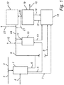
Fig. 1 is a schematic view of a system used for the method of forming urea by integration of an ammonia production process with a urea production process. -
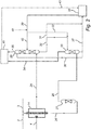
Fig. 2 is a schematic view of a system for the alternative integrated method of forming urea by integration of a part of an ammonia production process with a urea production process. - Carbon dioxide used as a reactant for a urea production process according to the present integrated method may originate from any combustion plant or apparatus, e.g., a conventional reformer. In one embodiment, the carbon dioxide originates from a steam reformer combustion apparatus part of an ammonia production process.
- Syngas, also called synthetic gas or synthesis gas, is produced when hydrocarbons react with water in a reactor apparatus, e.g., a steam reformer. Syngas is a gas mixture containing varying amounts of carbon monooxide and hydrogen. A steam reformer used to produce syngas is a tubular reactor fired from the outside to providing sufficient reaction energy for a reforming reaction. For this purpose, a fuel is subjected to combustion in the fire box on the outer side of the steam reformer tubes. Inside the tubes of a steam reformer,the steam reforming reaction takes place in the presence of a catalyst to producesyngas. Carbon monooxide in the syngas is subjected to a carbon monooxide shift reaction with water to produce carbon dioxide. After such production, the carbon dioxide is then separated from the hydrogen. The separated hydrogen is then reacted with nitrogen in the air to produce ammonia. In addition to the use of hydrogen as a reactant for ammonia production and the use of carbon dioxide produced from the carbon monooxide shift reaction, useful flue gases are also formed from the combustion of the fuel for the steam reformer. These flue gases contain nitrogen, carbon dioxide and other contaminants, e.g., NOx. Normally, the carbon dioxide present in the flue gas in an ammonia production process can be absorbed in a CAP (Chilled Ammonia Process) absorber operating at atmospheric pressure and a low temperature. Before entering the CAP absorber, the flue gas is cooled to enhance absorption of the carbon dioxide by a carbon dioxide-lean ammoniated solution present in the absorber. After the carbon dioxide absorption step, the once carbon dioxide-lean ammoniated solution is a carbon dioxide rich solution that requires regeneration in a subsequent regeneration step. This process is disclosed more in detail in
WO 2006/022885 . - Another method for syngas production is gasification of a carbon or hydrocarbon with oxygen in a gasification reactor. Here, the reaction energy is provided within the gasification reactor itself. Syngas so produced can be treated as described above to separate the hydrogen from the carbon dioxide. However, in accordance with the present process there is a need for another flue gas source to produce additional carbon dioxide. Under such circumstances, the same integration scheme as applied for steam reformers can be similarly applied hereto.
- Thus, syngas used in the present method is either formed in a steam reformation reaction or in a gasification reaction. In the steam reformation reaction, flue gas is produced by combustion during steam reforming. In the gasification reaction, the flue gas may originate from any source. The language "ammonia production process" and "ammonia production plant" used herein is intended to cover both of these reactions.
- The integrated method and system will now be disclosed more in detail with reference to
Fig. 1 , which illustrates the embodiment when both the syngas and the flue gas are formed during steam reformation. According toFig. 1 , an ammonia production plant 1 comprising a steam reformer 1 a (not shown) for combustion is provided with afeedstock 2, e.g., natural gas, oil or hydrocarbons, andsteam 3. The steam reformer 1 a is fired with afuel 4, e.g., natural gas. During the reaction between hydrocarbons and steam in the steam reformer 1 a, syngas is produced. A flue gas is also produced from firing of the steam reformer 1 a. Aflue gas stream 5 containing carbon dioxide and other contaminants is transported, optionally via one or more conventional purification steps, to aCAP absorber 10, in which carbon dioxide is absorbed. Further, afirst ammonia stream 6 containing ammonia from the reaction between hydrogen in the syngas and nitrogen from the air in the ammonia production plant 1 is separated into asecond ammonia stream 9 and athird ammonia stream 8.Ammonia stream 9 is added to a leansolvent stream 24 before reachingCAP absorber 10. The leansolvent stream 24 of recycled carbamate in a solution or slurry, also containing water, ammonia, and a low content of carbon dioxide, from a urea production process is added to theCAP absorber 10 as amixed stream 11.Mixed stream 11 is a mixture of thesecond ammonia stream 9 and the leansolvent stream 24. In theCAP absorber 10, carbon dioxide in theflue gas stream 5 is absorbed in the solution of themixed stream 11 to produce aclean gas stream 12.Clean gas stream 12 of treated flue gas having a low carbon dioxide content is emitted from theCAP absorber 10. A richsolvent stream 13 containing ammonia, water, and a high content of carbon dioxide is emitted fromCAP absorber 10 and transported under a high pressure, suitable for any urea synthesis reaction, to aurea synthesis reactor 15 in a urea production plant 15a (not shown). In theurea syntheis reactor 15, carbon dioxide and ammonia are reacted to produce urea. A mixture of urea produced, carbamate, excess ammonia and water is then transported in astream 17 to astripper 19, from which urea is separated in aurea stream 16. Ammonia and carbon dioxide fromstripper 19 are emitted in astream 20 in the form of a carbamate solution containing ammonia, carbon dioxide and water.Stream 20 or a part ofstream 20 is then transported as such in astream 21, and as such in leansolvent stream 24, to theabsorber 10. The balance instripper 19 is recyled back as astream 18 to theurea synthesis reactor 15 or to any other suitable place in urea production. Optionally, thestream 20 is subjected to waste water treatment in a wastewater treatment unit 22, wherein water is separated fromstream 20 to produce awater stream 23. Instead of recycling thestream 20 back to theurea synthesis reactor 15, as in a conventional urea production process, all or a part ofstream 20 is transported to theabsorber 10 for use in the ammonia production process in the form of the leansolvent stream 24. Thethird ammonia stream 8 originating fromfirst ammonia stream 6 is transported directly toureasynthesis reactor 15 in the urea production plant 15a. - Further, a
carbon dioxide stream 7 containing carbon dioxide originating and separated from the syngas produced in the ammonia production plant is transported directly to theurea synthesis reactor 15. The production of syngas may be designed for obtaining a sufficient amount of carbon dioxide for urea production, which will lead to some excess of ammonia. An additional carbon dioxide source would be any flue gas. If the carbon dioxide is taken from the flue gas, either the syngas production can be reduced (adjusted according to the desired level of ammonia production), or alternatively, any excess ammonia can be used in the urea production process to increase urea production. Such is accomplished by feeding additional carbon dioxide from the flue gas source as noted previously. Further, the leansolvent stream 24 of the recycled carbamate may be taken from any suitable place in the urea production plant 15a. It should be noted that each of the various streams described herein are transported in fluidly connected conduits, suitable for such purpose. - As disclosed above,
first ammonia stream 6 andcarbon dioxide stream 7 could alternatively be obtained from a syngas produced in a gasification reactor (not shown inFig. 1 ). Likewise,flue gas stream 5 containing carbon dioxide could be provided from any other source (not shown inFig. 1 , such as a boiler, e.g. a power boiler or any boiler supplying heat to a urea production plant). - Any other carbon dioxide capture technologies not using an ammoniated solvent cannot be integrated into the urea process as described herein, since the carbon dioxide absorbent solvent would comprise a chemical foreign to the urea production process, which would disturb urea production or even make it impossible. Further, the
flue gas stream 5 may be subjected to any conventional cleaning or separation processes not shown inFig. 1 before it is transported to theCAP absorber 10. The carbon dioxide source for the urea production process may also originate from, e.g., any fossil fuel fired boiler or process heater in the urea production plant 15a or elsewhere. - Thus, the need for a carbon dioxide desorption/solvent regeneration process as used in the conventional carbon dioxide capture process is eliminated in the present integrated method, thereby reducing energy and equipment costs.
- The language "lean solvent" and "rich solvent" as used herein means a concentration of ammonia in the lean
solvent stream 24 and in the richsolvent stream 13 of 2-12, preferably 6-10, moles per liter solution, a concentration of carbon dioxide in the leansolvent stream 24 of 0.2-4.0, preferably 1.5-4, moles per liter solution and a concentration of carbon dioxide in the richsolvent stream 13 of 1.0- 10.0, preferably 3.0 - 6.0, moles per liter solution. The ratio of the concentration of ammonia to the concentration of carbon dioxide in the richsolvent stream 13 is 1:1 to 3:1 preferably 3:2 to 5:2 in order to satisfy the stochiometrics of the urea reaction. If further ammonia is added via thesecond ammonia stream 9, the above-mentioned ammonia concentrations in themixed stream 11 and the richsolvent stream 13 will be changed. - In the embodiment of the alternative integrated method and system illustrated in
Fig. 2 , carbon dioxide produced in the ammonia production process is not per se integrated with the urea production process. Instead, a rich solvent stream from the absorption of the gas mixture of hydrogen and carbon dioxide (formed via a carbon monooxide shift reaction), originating from syngas produced in asteam reformer 14 or a gasification reactor during the ammonia production process, is used for the integration. - More precisely, hydrogen is typically produced during syngas production by steam reforming or gasification. Typically, physical absorption or adsorption processes are applied to separate the carbon dioxide from the hydrogen in the gas mixture of hydrogen and carbon dioxide. This occurs at elevated pressures, often much higher than those used during carbon dioxide absorption from flue gas in a high pressure absorber. After separation of carbon dioxide, the hydrogen is reacted with nitrogen in the air to form ammonia.
- In the present alternative integrated method, both the flue gas stream and the stream of the gas mixture of hydrogen and carbon dioxide, originating from the syngas stream, are subjected to carbon dioxide absorption. If the chilled ammonia process (CAP) is applied to absorb carbon dioxide from the stream of the gas mixture of carbon dioxide and hydrogen, it is also possible to use the lean solvent stream containing carbamate from the urea process, if necessary enriched with additional ammonia. Then a low pressure absorber for the flue gas and a high pressure absorber for the gas mixture of carbon dioxide and hydrogen are needed. Said lean solvent may be used either in parallel to the low pressure absorber for flue gas or in sequence, using a semi rich solvent for the absorption of carbon dioxide in the high pressure absorber. Both the semi rich solvent and the rich solvent formed after high pressure absorption is fed back to the urea production plant 15a, preferably direct to the
urea synthesis reactor 15 therein. - The advantages of this alternative integrated method are as follows. First, a combination of the two absorption processes (of carbon dioxide from flue gas and from syngas, respectively) using the same kind of solvent and same kind of principle (wet absorption) is obtained. Second, any need for desorption of carbon dioxide from the rich solvent is eliminated, since this rich solvent is used for the urea reaction. The rich solvent already contains ammonia and carbon dioxide as reactants for the urea process significantly reducingassociated energy and equipment costs. Third, no "foreign" chemical is added, such as an amine, as used in some carbon capture processes.
- Further, potentially the carbon dioxide lean and nitrogen rich flue gas stream following absorption can be used as feedstock for ammonia synthesis to replace at least a part of the air used for ammonia synthesis. Such could allow for increased ammonia production, since less oxygen containing air is then fed to the synthesis. Any smaller amounts of ammonia slippage into either the hydrogen stream or the nitrogen rich stream from the absorbers should not poison the ammonia synthesis reaction. As an option, a slip stream from the rich solution stream may be transported to the low pressure absorber to minimize ammonia slippage into the nitrogen rich stream.
- This embodiment of the alternative integrated method and system for the formation of urea by integration of a part of an ammonia production process with the urea production process is schematically illustrated in
Fig. 2 and will be disclosed in detail below with reference toFig. 2 . Although asteam reformer unit 14 is illustrated inFig. 2 , such could, in analogy with the system illustrated inFig. 1 , as an alternative be a gasification reactor in which syngas is formed. In that case, the flue gas used in the alternative integrated method is provided from any other source (not shown inFig. 2 ), such as a boiler, e.g. a power boiler or any boiler supplying heat to a urea production plant. Referring toFig. 2 asteam reformer 14 is provided with afeedstock 2, e.g., natural gas, oil, or hydrocarbons, and withsteam 3. Thesteam reformer 14 is fired with afuel 4, e.g., natural gas. During the reaction between carbonhydrates and steam in the steam reformer 14 a syngas containing hydrogen and carbon monooxide is produced. Asyngas stream 26 is transported to a carbonmonooxide shift unit 27, in which the carbon monooxide is subjected to a shift into carbon dioxide. The hydrogen/carbon dioxide stream 28 so obtained is transported directly to ahigh pressure absorber 33 having a pressure of 0.3-4 MPa, preferably 1-2.5 MPa. Further, a flue gas containing nitrogen, carbon dioxide, and other contaminants is emitted from thesteam reformer 14, and transported asflue gas stream 25 to alow pressure absorber 29 having a pressure of 0.08-0.15 MPa, preferably 0.095-0.11 MPa. - In the
high pressure absorber 33 carbon dioxide is absorbed and is then emitted therefrom in a richsolvent stream 37 containing carbon dioxide in a high concentration, water, and ammonia. This richsolvent stream 37 is then transported under a high pressure as a reactant to the urea synthesis reactor 38a (not shown) in aurea production plant 38. Ahydrogen stream 34 is emitted from thehigh pressure absorber 33 for use as a reactant in anammonia production unit 41. Optionally, aslip stream 36 of richsolvent stream 37 is transported to the top of thelow pressure absorber 29, where it is used to catch excess ammonia from the upcoming treatedflue gas stream 25 as necessary, before the cleaned flue gas, i.e.,nitrogen containing stream 35, is transported to theammonia production unit 41 for usage. - In the
low pressure absorber 29 carbon dioxide contained in theflue gas stream 25 is absorbed by means of leansolvent stream 42. Such leaveslow pressure absorber 29 as a semi richsolvent stream 30 containing absorbed carbon dioxide in a medium concentration, water, and ammonia. This semi richsolvent stream 30 is then transported tohigh pressure absorber 33. Optionally, apartial stream 31 of the semi richsolvent stream 30 is transported to theurea production plant 38. Before entering thelow pressure absorber 29,flue gas stream 25 may be subjected to one or more conventional purification steps, and is also cooled to a temperature of between 0 and 25°C, preferably to a temperature between 10 and 20°C. Cleaned flue gas containing nitrogen at a high percentage, which is emitted from thelow pressure absorber 29, can be transported as thenitrogen containing stream 35 to theammonia production unit 41. Thus, the hydrogen in thehydrogen stream 34 and the nitrogen in thenitrogen containing stream 35 are transported as reactants to theammonia production unit 41 in which the reaction between hydrogen and nitrogen takes place to produce ammonia. Arecycle stream 39 containing a mixture of ammonium carbamate, ammonium carbonate and ammonium bicarbonate, either in solution or in a slurry, also containing unreacted ammonia, carbon dioxide, carbonic acid and water originating from theurea production plant 38, is optionally provided with additional ammonia via anammonia stream 40 from theammonia production unit 41 forming a leansolvent stream 42 in the form of a ammonia solution containing carbon dioxide in a low concentration, ammonia, ammonium carbamate, ammonium carbonate, ammonium bicarbonate and water, wherein this leansolvent stream 42 is transported to thelow pressure absorber 29. Optionally, apartial stream 32 of thelean solution stream 42 may be transported directly to thehigh pressure absorber 33 or to the semi richsolvent stream 30. The balance of ammonia from theammonia production unit 41 is transported in partial-stream 43 to theurea production plant 38. - The concentration of ammonia in the lean
solvent stream 42, in the semi richsolvent stream 30 and in the richsolvent stream 37 is 2-12, preferably 6-10, moles per liter of solution. The concentration of carbon dioxide in the leansolvent stream 42 is 0.2-4.0, preferably 1.5-4, moles per liter solution. The concentration of carbon dioxide in the semi richsolvent stream 30 is 1.0-5.5, preferably 2.5-4.5, moles per liter solution. The concentration of carbon dioxide in the richsolvent stream 13 is 1.0-10.0, preferably 3.0-6.0, moles per liter solution. The ratio between the concentration of ammonia and the concentration of carbon dioxide instream 37 is preferably 1;1.5 to 1:2.5 in order to satisfy the stochiometrics of the urea reaction. - To summarize, the present invention relates to a method of forming urea by integration of an ammonia production process in a urea production process, and to a system for said method. It also refers to an alternative method of forming urea by integration of a part of an ammonia production process in a urea production process, and to a system for said alternative method.
- While the invention has been described with reference to a number of preferred embodiments, it will be understood by those skilled in the art that various changes may be made and equivalents may be substituted for elements thereof without departing from the scope of the present invention. In addition, many modifications may be made to adapt a particular situation or material to the teachings of the invention without departing from the essential scope thereof. Therefore, it is intended that the invention not be limited to the particular embodiments disclosed as the best mode contemplated for carrying out this invention, but that the invention will include all embodiments falling within the scope of the appended claims.
Claims (28)
- A method of forming urea by integration of an ammonia production process in a urea production process comprising:obtaining ammonia and carbon dioxide and a flue gas for a first ammonia stream (6), a carbon dioxide stream (7), and a flue gas stream (5) containing carbon dioxide,separating first ammonia stream (6) into a second ammonia stream (9) transported to an absorber (10) and into a third ammonia stream (8) transported to a urea synthesis reactor (15) in a urea production plant (15a),transporting carbon dioxide stream (7) to the urea synthesis reactor (15),transporting flue gas stream (5) to the absorber (10) for carbon dioxide absorption into a mixed stream (11) comprising the second ammonia stream (9) and a lean solvent stream (24) containing ammonia and a lower content of carbon dioxide,transporting a rich solvent stream (13) containing ammonia and a higher content of carbon dioxide emitted from the absorber (10), to the urea synthesis reactor (15) for the production of urea, andrecycling lean solvent stream (24) containing ammonia and a lower content of carbon dioxide from the urea production plant (15a) to the absorber (10).
- The method according to claim 1, wherein the flue gas stream (5) is obtained during combustion in the ammonia production plant (1).
- The method according to claim 2 or 3, wherein the combustion in the ammonia production plant (1) is performed in a steam reformer (1 a).
- The method according to any one of the preceding claims, wherein the flue gas stream (5) is cooled to a temperature of 0-25°C, preferably to a temperature of 10-20°C, before it is transported to the absorber (10).
- The method according to any one of the preceding claims, wherein the absorber (10) is a CAP (Chilled Ammonia Process) absorber.
- The method according to any one of the preceding claims, wherein a clean gas stream (12) is emitted from the absorber (10).
- The method according to any one of the preceding claims, wherein the concentration of ammonia in the mixed stream (11) and in the rich solvent stream (13) is 2-12, preferably 6-10, moles per liter solution, wherein the concentration of carbon dioxide in the lean solvent stream (24) is 0.2-4.0, preferably 1.5-4, moles per liter solution, and wherein the concentration of carbon dioxide in the rich solvent stream (13) is 1.0-10.0, preferably 3-6.0, moles per liter solution.
- The method according to any one of the preceding claims, wherein the ratio between the concentration of ammonia and the concentration of carbon dioxide in the streams (24) and (13), respectively is 1:1 to 3:1, preferably 3:2 to 5:2.
- A method of forming urea by integration of a part of an ammonia production process in a urea production process, comprising:obtaining a hydrogen/carbon dioxide stream (28) from an ammonia production process, and a flue gas stream (25) containing carbon dioxide and nitrogen,transporting flue gas stream (25) to a low pressure absorber (29),transporting hydrogen/carbon dioxide stream (28) to a high pressure absorber (33) with a semi rich solvent stream (30) containing absorbed carbon dioxide transported from the low pressure absorber (29) to the high pressure absorber (33),transporting a rich solvent stream (37) containing ammonia and a higher content of carbon dioxide emitted from the high pressure absorber (33) to a urea production plant (38) for the production of urea,recycling stream (39) containing carbamate in a solution or slurry also containing ammonia, carbon dioxide, and water from the urea production plant (38) to the low pressure absorber (29), andtransporting stream (43) from the ammonia production unit (41) to the urea production plant (38).
- The method according to claim 9, wherein the flue gas stream (25) is obtained during combustion in a stream reformer (14) in the ammonia production process.
- The method according to claims 9 and 10, wherein a syngas stream (26) containing hydrogen and carbon monooxide, and formed during a steam reforming reaction of the ammonia production process, is transported to a carbon monooxide shift unit (27) in which the carbon monooxide (26) is converted into carbon dioxide to form the hydrogen/carbon dioxide stream (28).
- The method according to any one of claims 9-11, wherein a nitrogen containing stream (35) is emitted from the low pressure absorber (29), and a hydrogen stream (34) is emitted from the high pressure absorber (33), wherein both the nitrogen containing stream (35) and the hydrogen containing stream (34) are transported to the ammonia production unit (41) and are reacted for the production of ammonia.
- The method according to any one of claims 9-12, wherein an ammonia stream (40), optionally originating from the ammonia production unit (41), is added to the recycle stream (39) used to generate a lean solvent stream (42) containing ammonia and a low content of carbon dioxide.
- The method according to any one of claims 9-13, wherein a slip tream (36) diverted from the rich solvent stream (37) is transported the low pressure absorber (29).
- The method according to any one of claims 9-14, wherein a partial stream (32) of the lean solvent stream (42) is added to the high pressure absorber (33) or to the semi rich solvent stream (30).
- The method according to any one of claims 9-15, wherein a partial stream (31) of the semi rich solvent stream (30) is transported to the urea production plant (38).
- The method according to any one of claims 9-16, wherein the pressure in the low pressure absorber (29) is 0.08-0.15 MPa, preferably 0.095-0.11 MPa, and the pressure in the high pressure absorber (33) is 0.3-4.0 MPa, preferably 0.095-0.11 MPa.
- The method according to any one of claims 9-17, wherein the concentration of ammonia in the lean solvent stream (42), in the semi rich solvent stream (30), and in the rich solvent stream (37) is 2-12, preferably 6-9, moles per liter solution.
- The method according to any one of claims 9-18, wherein the concentration of carbon dioxide in the lean solvent stream (42) is 0.2-4.0, preferably 1.5-4.0, moles per liter solution, the concentration of carbon dioxide in the semi rich solvent stream (30) is 1.0-5.5, preferably 2.5-4.5, moles per liter of solution, and the concentration of carbon dioxide in the rich solution stream (37) is 1.0-10.0, preferably 3.0-6.0, moles per liter solution.
- The method according to any one of claims 9-19, wherein the ratio between the concentration of ammonia and the concentration of carbon dioxide in the streams (42), (30), and (37), respectively, is 1:1 to 3:1, preferably 3:2 to 5:2.
- A system for the method according to any one of claims 1-8 of forming urea by integration of an ammonia production process with that of a urea production process, wherein said system comprises an ammonia production plant (1), an absorber (10), and a urea synthesis reactor (15) in a urea production plant, wherein a conduit for a first ammonia stream (6) from the ammonia production plant (1) is separated into a conduit for a second ammonia stream (9) fluidly connected to the absorber (10) or to a conduit for a lean solvent stream (24) thus forming a mixed stream (11), and into a conduit for a third ammonia stream (8) fluidly connected to the urea synthesis reactor (15), wherein a conduit for a flue gas stream (5) containing carbon dioxide is fluidly connected between the ammonia production plant (1), or another flue gas source, and the absorber (10), wherein a conduit for a carbon dioxide stream (7) is fluidly connected between the ammonia production plant (1) and the urea synthesis reactor (15), wherein a conduit for a rich solvent stream (13) is fluidly connected between the absorber (10) and the urea synthesis reactor (15), and wherein the conduit for a lean solvent stream (24) is arranged between the urea production plant and the absorber (10).
- The system according to claim 21, wherein it comprises a conduit for a clean gas stream (12) fluidly connected to the absorber (10).
- A system for the method according to any one of claims 9-22 of forming urea by integration of a part of an ammonia production process with that of a urea production process, wherein it comprises a steam reformer (14) or a gasification reactor of an ammonia production plant, a low pressure absorber (29), a high pressure absorber (33), and a urea production plant (38), wherein a conduit for a flue gas stream (25) is connected between the steam reformer (14), the gasification reactor, or another flue gas source, and the low pressure absorber (29), wherein a conduit for a hydrogen/carbon dioxide stream (28) is arranged between the steam reformer (14) or the gasification reactor and the high pressure absorber (33), wherein a conduit for a semi rich solvent stream (30) is fluidly connected between the low pressure absorber (29) and the high pressure absorber (33), wherein a conduit for a rich solvent stream (37) is fluidly connected between the high pressure absorber (33) and the urea production plant (38), and wherein a conduit for a lean solvent stream (42) is arranged between the urea production plant (38) and the low pressure absorber (29).
- The system according to claim 23, wherein it also comprises an ammonia production unit (41), a conduit for a hydrogen stream (34) fluidly connected between the high pressure absorber (33) and the ammonia production unit (41), a conduit for a nitrogen containing stream (35) fluidly connected between the low pressure absorber (29) and the ammonia production unit (41), and a conduit for a stream (43) of the balance of ammonia fluidly connected between the ammonia production unit (41) and the urea production plant (38).
- The system according to any one of claims 23 and 24, wherein it comprises a carbon monooxide shift unit (27) for the conversion of carbon monooxide into carbon dioxide, wherein a conduit for a syngas stream (26) containing hydrogen and carbon monooxide is fluidly connected between the steam reformer (14) or the gasification reactor and the carbon monooxide shift unit (27), and wherein the conduit for the hydrogen/ carbon dioxide stream (28) is fluidly connected between the carbon monooxide shift unit (27) and the high pressure absorber (33).
- The system according to any one of claims 23-25, wherein it comprises a conduit for a partial stream (31) of the semi rich solvent stream (30) fluidly connected between the conduit for the semi rich solvent stream (30) and the conduit for the rich solvent stream (37).
- The system according to any one of claims 23-26, wherein a conduit for a recycle stream (39) containing carbamate in a solution or in a slurry, also containing ammonia, carbon dioxide and water, is fluidly connected between the urea production plant (38) and the conduit for the lean solvent stream (42), and wherein a conduit for an ammonia stream (40) is connected to the conduit for the recycle stream (39).
- The system according to any one of claims 23-27, wherein a conduit for a partial stream (32) of the lean solvent stream (42) is fluidly connected between the conduit for the lean solvent stream (42) and the conduit for the semi rich solvent stream (30) or the high pressure absorber (33).
Priority Applications (10)
| Application Number | Priority Date | Filing Date | Title |
|---|---|---|---|
| EP12151354.3A EP2617708B1 (en) | 2012-01-17 | 2012-01-17 | A method of forming urea by integration of an ammonia production process in a urea production process and a system therefor |
| NO12151354A NO2617708T3 (en) | 2012-01-17 | 2012-01-17 | |
| TW102101670A TWI568713B (en) | 2012-01-17 | 2013-01-16 | A method of forming urea by integration of an ammonia production process in a urea production process and a system therefor |
| PCT/IB2013/050399 WO2013108191A1 (en) | 2012-01-17 | 2013-01-16 | A method of forming urea by integration of an ammonia production process in a urea production process and a system therefor |
| CN201380005795.9A CN104039758B (en) | 2012-01-17 | 2013-01-16 | Method and the system thereof of urea is formed by ammonia production process integrated in urea production process |
| RU2014133543/04A RU2569306C1 (en) | 2012-01-17 | 2013-01-16 | Method of producing urea by combining ammonia production process and urea production process and system therefor |
| CA2861431A CA2861431C (en) | 2012-01-17 | 2013-01-16 | A method of forming urea by integration of an ammonia production process in a urea production process and a system therefor |
| KR1020177000744A KR20170007542A (en) | 2012-01-17 | 2013-01-16 | A method of forming urea by integration of an ammonia production process in a urea production process and a system therefor |
| AU2013210737A AU2013210737B2 (en) | 2012-01-17 | 2013-01-16 | A method of forming urea by integration of an ammonia production process in a urea production process and a system therefor |
| KR1020147022775A KR101701582B1 (en) | 2012-01-17 | 2013-01-16 | A method of forming urea by integration of an ammonia production process in a urea production process and a system therefor |
Applications Claiming Priority (1)
| Application Number | Priority Date | Filing Date | Title |
|---|---|---|---|
| EP12151354.3A EP2617708B1 (en) | 2012-01-17 | 2012-01-17 | A method of forming urea by integration of an ammonia production process in a urea production process and a system therefor |
Publications (2)
| Publication Number | Publication Date |
|---|---|
| EP2617708A1 true EP2617708A1 (en) | 2013-07-24 |
| EP2617708B1 EP2617708B1 (en) | 2017-08-16 |
Family
ID=47757668
Family Applications (1)
| Application Number | Title | Priority Date | Filing Date |
|---|---|---|---|
| EP12151354.3A Active EP2617708B1 (en) | 2012-01-17 | 2012-01-17 | A method of forming urea by integration of an ammonia production process in a urea production process and a system therefor |
Country Status (9)
| Country | Link |
|---|---|
| EP (1) | EP2617708B1 (en) |
| KR (2) | KR20170007542A (en) |
| CN (1) | CN104039758B (en) |
| AU (1) | AU2013210737B2 (en) |
| CA (1) | CA2861431C (en) |
| NO (1) | NO2617708T3 (en) |
| RU (1) | RU2569306C1 (en) |
| TW (1) | TWI568713B (en) |
| WO (1) | WO2013108191A1 (en) |
Cited By (4)
| Publication number | Priority date | Publication date | Assignee | Title |
|---|---|---|---|---|
| EP2877447B1 (en) | 2012-07-25 | 2016-06-15 | Casale SA | Use of urea synthesis purge gas in an integrated ammonia-urea process and related plant |
| WO2019224429A1 (en) * | 2018-05-22 | 2019-11-28 | Andritz Oy | Method for producing cellulose carbamate |
| WO2021099679A1 (en) * | 2019-11-20 | 2021-05-27 | Andritz Oy | Method for producing cellulose carbamate |
| CN113231094A (en) * | 2021-05-08 | 2021-08-10 | 山西铭睿恒信环保工程有限公司 | Monoatomic catalytic material for removing refractory organic pollutants and preparation method thereof |
Families Citing this family (5)
| Publication number | Priority date | Publication date | Assignee | Title |
|---|---|---|---|---|
| US10106430B2 (en) | 2013-12-30 | 2018-10-23 | Saudi Arabian Oil Company | Oxycombustion systems and methods with thermally integrated ammonia synthesis |
| EP3366670A1 (en) * | 2017-02-27 | 2018-08-29 | Casale Sa | A process and system to capture ammonia from a purge gas of a urea plant |
| GB201705487D0 (en) * | 2017-04-05 | 2017-05-17 | Johnson Matthey Plc | Process |
| IT201700090748A1 (en) * | 2017-08-04 | 2019-02-04 | Saipem Spa | PROCESS AND PRODUCTION PLANT FOR UREA USING CO2 PRODUCED THROUGH BONES-COMBUSTION |
| DE102017222030A1 (en) * | 2017-12-06 | 2019-06-06 | Thyssenkrupp Ag | Process for the provision of CO2 for the synthesis of urea from smoke and synthesis gas |
Citations (3)
| Publication number | Priority date | Publication date | Assignee | Title |
|---|---|---|---|---|
| GB1359715A (en) * | 1970-09-03 | 1974-07-10 | Snam Progetti | Integrated process for the production of urea |
| WO2006022885A1 (en) | 2004-08-06 | 2006-03-02 | Eig, Inc. | Ultra cleaning of combustion gas including the removal of co2 |
| WO2008135150A1 (en) | 2007-05-02 | 2008-11-13 | Evonik Energy Services Gmbh | Method for purifying flue gases from incinerators and then producing urea |
Family Cites Families (7)
| Publication number | Priority date | Publication date | Assignee | Title |
|---|---|---|---|---|
| US4013718A (en) * | 1970-09-03 | 1977-03-22 | Snam Progetti S.P.A. | Integrated process for the production of urea |
| IT1065422B (en) * | 1976-12-23 | 1985-02-25 | Snam Progetti | INTEGRATED AMMONIA-UREA PROCESS FOR UREA PRODUCTION |
| US4235816A (en) * | 1979-03-08 | 1980-11-25 | Snamprogetti S.P.A. | Integrated ammonia-urea process |
| EP0905127B1 (en) * | 1997-09-20 | 2001-11-28 | Urea Casale S.A. | Process for combined production of ammonia and urea |
| EP1188710A3 (en) * | 2000-09-15 | 2003-10-29 | Haldor Topsoe A/S | Process for the integrated preparation of ammonia and urea |
| CN100522314C (en) * | 2004-08-06 | 2009-08-05 | Eig公司 | Including the removal of CO2Ultra-cleaning of combustion gases |
| EP1626042A1 (en) * | 2004-08-10 | 2006-02-15 | Urea Casale S.A. | Process for urea production from ammonia and carbon dioxide |
-
2012
- 2012-01-17 EP EP12151354.3A patent/EP2617708B1/en active Active
- 2012-01-17 NO NO12151354A patent/NO2617708T3/no unknown
-
2013
- 2013-01-16 TW TW102101670A patent/TWI568713B/en not_active IP Right Cessation
- 2013-01-16 KR KR1020177000744A patent/KR20170007542A/en not_active Withdrawn
- 2013-01-16 KR KR1020147022775A patent/KR101701582B1/en active Active
- 2013-01-16 AU AU2013210737A patent/AU2013210737B2/en not_active Ceased
- 2013-01-16 CA CA2861431A patent/CA2861431C/en active Active
- 2013-01-16 RU RU2014133543/04A patent/RU2569306C1/en not_active IP Right Cessation
- 2013-01-16 WO PCT/IB2013/050399 patent/WO2013108191A1/en not_active Ceased
- 2013-01-16 CN CN201380005795.9A patent/CN104039758B/en active Active
Patent Citations (3)
| Publication number | Priority date | Publication date | Assignee | Title |
|---|---|---|---|---|
| GB1359715A (en) * | 1970-09-03 | 1974-07-10 | Snam Progetti | Integrated process for the production of urea |
| WO2006022885A1 (en) | 2004-08-06 | 2006-03-02 | Eig, Inc. | Ultra cleaning of combustion gas including the removal of co2 |
| WO2008135150A1 (en) | 2007-05-02 | 2008-11-13 | Evonik Energy Services Gmbh | Method for purifying flue gases from incinerators and then producing urea |
Cited By (10)
| Publication number | Priority date | Publication date | Assignee | Title |
|---|---|---|---|---|
| EP2877447B1 (en) | 2012-07-25 | 2016-06-15 | Casale SA | Use of urea synthesis purge gas in an integrated ammonia-urea process and related plant |
| WO2019224429A1 (en) * | 2018-05-22 | 2019-11-28 | Andritz Oy | Method for producing cellulose carbamate |
| CN112166127A (en) * | 2018-05-22 | 2021-01-01 | 安德里兹公司 | Process for producing cellulose carbamate |
| JP2021523963A (en) * | 2018-05-22 | 2021-09-09 | アンドリッツ オサケ ユキチュア | Methods for Producing Cellulose Carbamate |
| CN112166127B (en) * | 2018-05-22 | 2022-09-02 | 安德里兹公司 | Process for producing cellulose carbamate |
| US11584804B2 (en) | 2018-05-22 | 2023-02-21 | Andritz Oy | Method for producing cellulose carbamate |
| JP7231653B2 (en) | 2018-05-22 | 2023-03-01 | アンドリッツ オサケ ユキチュア | Method for producing cellulose carbamate |
| WO2021099679A1 (en) * | 2019-11-20 | 2021-05-27 | Andritz Oy | Method for producing cellulose carbamate |
| CN113231094A (en) * | 2021-05-08 | 2021-08-10 | 山西铭睿恒信环保工程有限公司 | Monoatomic catalytic material for removing refractory organic pollutants and preparation method thereof |
| CN113231094B (en) * | 2021-05-08 | 2023-04-04 | 山西铭睿恒信环保工程有限公司 | Monoatomic catalytic material for removing refractory organic pollutants and preparation method thereof |
Also Published As
| Publication number | Publication date |
|---|---|
| NO2617708T3 (en) | 2018-01-13 |
| AU2013210737A1 (en) | 2014-08-07 |
| CA2861431C (en) | 2016-06-28 |
| AU2013210737B2 (en) | 2015-11-26 |
| TW201335120A (en) | 2013-09-01 |
| KR20170007542A (en) | 2017-01-18 |
| KR101701582B1 (en) | 2017-02-01 |
| WO2013108191A9 (en) | 2014-03-06 |
| RU2569306C1 (en) | 2015-11-20 |
| CA2861431A1 (en) | 2013-07-25 |
| CN104039758B (en) | 2016-07-13 |
| TWI568713B (en) | 2017-02-01 |
| WO2013108191A1 (en) | 2013-07-25 |
| EP2617708B1 (en) | 2017-08-16 |
| KR20150022741A (en) | 2015-03-04 |
| CN104039758A (en) | 2014-09-10 |
Similar Documents
| Publication | Publication Date | Title |
|---|---|---|
| AU2013210737B2 (en) | A method of forming urea by integration of an ammonia production process in a urea production process and a system therefor | |
| EP2412668A1 (en) | A method and apparatus for treating a sour gas | |
| US8535613B2 (en) | Method and apparatus for separating acidic gases from syngas | |
| US9428449B2 (en) | Method of forming urea by integration of an ammonia production process in a urea production process and a system therefor | |
| WO2014041645A1 (en) | Reforming device and devices for manufacturing chemical products comprising same | |
| US20210198104A1 (en) | Method for the preparation of ammonia synthesis gas | |
| RU2758773C2 (en) | Method for producing formaldehyde-stabilised urea | |
| EA021500B1 (en) | Co-production of methanol and ammonia | |
| US20100210885A1 (en) | System and process of light chain hydrocarbon synthesis | |
| Damanabi et al. | Potential of tri-reforming process and membrane technology for improving ammonia production and CO2 reduction | |
| AU2018229396B2 (en) | Ammonia-urea integrated process and plant | |
| CA2357256C (en) | Process for the integrated preparation of ammonia and urea | |
| US10196348B2 (en) | Method for revamping a urea production complex | |
| US20210261424A1 (en) | Method for avoiding voc and hap emissions from synthesis gas-processing systems | |
| WO2005099869A2 (en) | Process to control nitrogen-containing compounds in synthesis gas | |
| US9682343B2 (en) | Sour syngas treatment apparatuses and processes for treating sour syngas comprising sulfur components and carbon dioxide | |
| CH637633A5 (en) | INTEGRATED AMMONIA-UREA PROCEDURE. | |
| JP2013209392A (en) | Method for concentrating and refining propylene oxide |
Legal Events
| Date | Code | Title | Description |
|---|---|---|---|
| PUAI | Public reference made under article 153(3) epc to a published international application that has entered the european phase |
Free format text: ORIGINAL CODE: 0009012 |
|
| AK | Designated contracting states |
Kind code of ref document: A1 Designated state(s): AL AT BE BG CH CY CZ DE DK EE ES FI FR GB GR HR HU IE IS IT LI LT LU LV MC MK MT NL NO PL PT RO RS SE SI SK SM TR |
|
| AX | Request for extension of the european patent |
Extension state: BA ME |
|
| 17P | Request for examination filed |
Effective date: 20131030 |
|
| RBV | Designated contracting states (corrected) |
Designated state(s): AL AT BE BG CH CY CZ DE DK EE ES FI FR GB GR HR HU IE IS IT LI LT LU LV MC MK MT NL NO PL PT RO RS SE SI SK SM TR |
|
| 17Q | First examination report despatched |
Effective date: 20160128 |
|
| RAP1 | Party data changed (applicant data changed or rights of an application transferred) |
Owner name: GENERAL ELECTRIC TECHNOLOGY GMBH |
|
| GRAP | Despatch of communication of intention to grant a patent |
Free format text: ORIGINAL CODE: EPIDOSNIGR1 |
|
| INTG | Intention to grant announced |
Effective date: 20170222 |
|
| GRAS | Grant fee paid |
Free format text: ORIGINAL CODE: EPIDOSNIGR3 |
|
| GRAA | (expected) grant |
Free format text: ORIGINAL CODE: 0009210 |
|
| AK | Designated contracting states |
Kind code of ref document: B1 Designated state(s): AL AT BE BG CH CY CZ DE DK EE ES FI FR GB GR HR HU IE IS IT LI LT LU LV MC MK MT NL NO PL PT RO RS SE SI SK SM TR |
|
| REG | Reference to a national code |
Ref country code: GB Ref legal event code: FG4D |
|
| REG | Reference to a national code |
Ref country code: CH Ref legal event code: EP |
|
| REG | Reference to a national code |
Ref country code: IE Ref legal event code: FG4D |
|
| REG | Reference to a national code |
Ref country code: AT Ref legal event code: REF Ref document number: 918881 Country of ref document: AT Kind code of ref document: T Effective date: 20170915 |
|
| REG | Reference to a national code |
Ref country code: DE Ref legal event code: R096 Ref document number: 602012035889 Country of ref document: DE |
|
| REG | Reference to a national code |
Ref country code: NL Ref legal event code: MP Effective date: 20170816 |
|
| REG | Reference to a national code |
Ref country code: LT Ref legal event code: MG4D |
|
| REG | Reference to a national code |
Ref country code: AT Ref legal event code: MK05 Ref document number: 918881 Country of ref document: AT Kind code of ref document: T Effective date: 20170816 |
|
| PG25 | Lapsed in a contracting state [announced via postgrant information from national office to epo] |
Ref country code: LT Free format text: LAPSE BECAUSE OF FAILURE TO SUBMIT A TRANSLATION OF THE DESCRIPTION OR TO PAY THE FEE WITHIN THE PRESCRIBED TIME-LIMIT Effective date: 20170816 Ref country code: NL Free format text: LAPSE BECAUSE OF FAILURE TO SUBMIT A TRANSLATION OF THE DESCRIPTION OR TO PAY THE FEE WITHIN THE PRESCRIBED TIME-LIMIT Effective date: 20170816 Ref country code: SE Free format text: LAPSE BECAUSE OF FAILURE TO SUBMIT A TRANSLATION OF THE DESCRIPTION OR TO PAY THE FEE WITHIN THE PRESCRIBED TIME-LIMIT Effective date: 20170816 Ref country code: FI Free format text: LAPSE BECAUSE OF FAILURE TO SUBMIT A TRANSLATION OF THE DESCRIPTION OR TO PAY THE FEE WITHIN THE PRESCRIBED TIME-LIMIT Effective date: 20170816 Ref country code: AT Free format text: LAPSE BECAUSE OF FAILURE TO SUBMIT A TRANSLATION OF THE DESCRIPTION OR TO PAY THE FEE WITHIN THE PRESCRIBED TIME-LIMIT Effective date: 20170816 |
|
| REG | Reference to a national code |
Ref country code: NO Ref legal event code: T2 Effective date: 20170816 |
|
| PG25 | Lapsed in a contracting state [announced via postgrant information from national office to epo] |
Ref country code: LV Free format text: LAPSE BECAUSE OF FAILURE TO SUBMIT A TRANSLATION OF THE DESCRIPTION OR TO PAY THE FEE WITHIN THE PRESCRIBED TIME-LIMIT Effective date: 20170816 Ref country code: GR Free format text: LAPSE BECAUSE OF FAILURE TO SUBMIT A TRANSLATION OF THE DESCRIPTION OR TO PAY THE FEE WITHIN THE PRESCRIBED TIME-LIMIT Effective date: 20171117 Ref country code: RS Free format text: LAPSE BECAUSE OF FAILURE TO SUBMIT A TRANSLATION OF THE DESCRIPTION OR TO PAY THE FEE WITHIN THE PRESCRIBED TIME-LIMIT Effective date: 20170816 Ref country code: PL Free format text: LAPSE BECAUSE OF FAILURE TO SUBMIT A TRANSLATION OF THE DESCRIPTION OR TO PAY THE FEE WITHIN THE PRESCRIBED TIME-LIMIT Effective date: 20170816 Ref country code: IS Free format text: LAPSE BECAUSE OF FAILURE TO SUBMIT A TRANSLATION OF THE DESCRIPTION OR TO PAY THE FEE WITHIN THE PRESCRIBED TIME-LIMIT Effective date: 20171216 Ref country code: BG Free format text: LAPSE BECAUSE OF FAILURE TO SUBMIT A TRANSLATION OF THE DESCRIPTION OR TO PAY THE FEE WITHIN THE PRESCRIBED TIME-LIMIT Effective date: 20171116 Ref country code: ES Free format text: LAPSE BECAUSE OF FAILURE TO SUBMIT A TRANSLATION OF THE DESCRIPTION OR TO PAY THE FEE WITHIN THE PRESCRIBED TIME-LIMIT Effective date: 20170816 |
|
| PG25 | Lapsed in a contracting state [announced via postgrant information from national office to epo] |
Ref country code: CZ Free format text: LAPSE BECAUSE OF FAILURE TO SUBMIT A TRANSLATION OF THE DESCRIPTION OR TO PAY THE FEE WITHIN THE PRESCRIBED TIME-LIMIT Effective date: 20170816 Ref country code: DK Free format text: LAPSE BECAUSE OF FAILURE TO SUBMIT A TRANSLATION OF THE DESCRIPTION OR TO PAY THE FEE WITHIN THE PRESCRIBED TIME-LIMIT Effective date: 20170816 Ref country code: RO Free format text: LAPSE BECAUSE OF FAILURE TO SUBMIT A TRANSLATION OF THE DESCRIPTION OR TO PAY THE FEE WITHIN THE PRESCRIBED TIME-LIMIT Effective date: 20170816 |
|
| REG | Reference to a national code |
Ref country code: DE Ref legal event code: R097 Ref document number: 602012035889 Country of ref document: DE |
|
| PG25 | Lapsed in a contracting state [announced via postgrant information from national office to epo] |
Ref country code: SM Free format text: LAPSE BECAUSE OF FAILURE TO SUBMIT A TRANSLATION OF THE DESCRIPTION OR TO PAY THE FEE WITHIN THE PRESCRIBED TIME-LIMIT Effective date: 20170816 Ref country code: SK Free format text: LAPSE BECAUSE OF FAILURE TO SUBMIT A TRANSLATION OF THE DESCRIPTION OR TO PAY THE FEE WITHIN THE PRESCRIBED TIME-LIMIT Effective date: 20170816 Ref country code: EE Free format text: LAPSE BECAUSE OF FAILURE TO SUBMIT A TRANSLATION OF THE DESCRIPTION OR TO PAY THE FEE WITHIN THE PRESCRIBED TIME-LIMIT Effective date: 20170816 Ref country code: IT Free format text: LAPSE BECAUSE OF FAILURE TO SUBMIT A TRANSLATION OF THE DESCRIPTION OR TO PAY THE FEE WITHIN THE PRESCRIBED TIME-LIMIT Effective date: 20170816 |
|
| PLBE | No opposition filed within time limit |
Free format text: ORIGINAL CODE: 0009261 |
|
| STAA | Information on the status of an ep patent application or granted ep patent |
Free format text: STATUS: NO OPPOSITION FILED WITHIN TIME LIMIT |
|
| 26N | No opposition filed |
Effective date: 20180517 |
|
| PG25 | Lapsed in a contracting state [announced via postgrant information from national office to epo] |
Ref country code: SI Free format text: LAPSE BECAUSE OF FAILURE TO SUBMIT A TRANSLATION OF THE DESCRIPTION OR TO PAY THE FEE WITHIN THE PRESCRIBED TIME-LIMIT Effective date: 20170816 |
|
| REG | Reference to a national code |
Ref country code: CH Ref legal event code: PL |
|
| GBPC | Gb: european patent ceased through non-payment of renewal fee |
Effective date: 20180117 |
|
| PG25 | Lapsed in a contracting state [announced via postgrant information from national office to epo] |
Ref country code: LU Free format text: LAPSE BECAUSE OF NON-PAYMENT OF DUE FEES Effective date: 20180117 Ref country code: FR Free format text: LAPSE BECAUSE OF NON-PAYMENT OF DUE FEES Effective date: 20180131 |
|
| REG | Reference to a national code |
Ref country code: IE Ref legal event code: MM4A |
|
| REG | Reference to a national code |
Ref country code: FR Ref legal event code: ST Effective date: 20180928 |
|
| REG | Reference to a national code |
Ref country code: BE Ref legal event code: MM Effective date: 20180131 |
|
| PG25 | Lapsed in a contracting state [announced via postgrant information from national office to epo] |
Ref country code: LI Free format text: LAPSE BECAUSE OF NON-PAYMENT OF DUE FEES Effective date: 20180131 Ref country code: GB Free format text: LAPSE BECAUSE OF NON-PAYMENT OF DUE FEES Effective date: 20180117 Ref country code: CH Free format text: LAPSE BECAUSE OF NON-PAYMENT OF DUE FEES Effective date: 20180131 Ref country code: BE Free format text: LAPSE BECAUSE OF NON-PAYMENT OF DUE FEES Effective date: 20180131 |
|
| PG25 | Lapsed in a contracting state [announced via postgrant information from national office to epo] |
Ref country code: IE Free format text: LAPSE BECAUSE OF NON-PAYMENT OF DUE FEES Effective date: 20180117 |
|
| PG25 | Lapsed in a contracting state [announced via postgrant information from national office to epo] |
Ref country code: MC Free format text: LAPSE BECAUSE OF FAILURE TO SUBMIT A TRANSLATION OF THE DESCRIPTION OR TO PAY THE FEE WITHIN THE PRESCRIBED TIME-LIMIT Effective date: 20170816 |
|
| PG25 | Lapsed in a contracting state [announced via postgrant information from national office to epo] |
Ref country code: MT Free format text: LAPSE BECAUSE OF NON-PAYMENT OF DUE FEES Effective date: 20180117 |
|
| PG25 | Lapsed in a contracting state [announced via postgrant information from national office to epo] |
Ref country code: TR Free format text: LAPSE BECAUSE OF FAILURE TO SUBMIT A TRANSLATION OF THE DESCRIPTION OR TO PAY THE FEE WITHIN THE PRESCRIBED TIME-LIMIT Effective date: 20170816 |
|
| PG25 | Lapsed in a contracting state [announced via postgrant information from national office to epo] |
Ref country code: PT Free format text: LAPSE BECAUSE OF FAILURE TO SUBMIT A TRANSLATION OF THE DESCRIPTION OR TO PAY THE FEE WITHIN THE PRESCRIBED TIME-LIMIT Effective date: 20170816 Ref country code: HU Free format text: LAPSE BECAUSE OF FAILURE TO SUBMIT A TRANSLATION OF THE DESCRIPTION OR TO PAY THE FEE WITHIN THE PRESCRIBED TIME-LIMIT; INVALID AB INITIO Effective date: 20120117 |
|
| PG25 | Lapsed in a contracting state [announced via postgrant information from national office to epo] |
Ref country code: CY Free format text: LAPSE BECAUSE OF FAILURE TO SUBMIT A TRANSLATION OF THE DESCRIPTION OR TO PAY THE FEE WITHIN THE PRESCRIBED TIME-LIMIT Effective date: 20170816 Ref country code: MK Free format text: LAPSE BECAUSE OF NON-PAYMENT OF DUE FEES Effective date: 20170816 Ref country code: HR Free format text: LAPSE BECAUSE OF FAILURE TO SUBMIT A TRANSLATION OF THE DESCRIPTION OR TO PAY THE FEE WITHIN THE PRESCRIBED TIME-LIMIT Effective date: 20170816 |
|
| PG25 | Lapsed in a contracting state [announced via postgrant information from national office to epo] |
Ref country code: AL Free format text: LAPSE BECAUSE OF FAILURE TO SUBMIT A TRANSLATION OF THE DESCRIPTION OR TO PAY THE FEE WITHIN THE PRESCRIBED TIME-LIMIT Effective date: 20170816 |
|
| PGFP | Annual fee paid to national office [announced via postgrant information from national office to epo] |
Ref country code: NO Payment date: 20251218 Year of fee payment: 15 |
|
| PGFP | Annual fee paid to national office [announced via postgrant information from national office to epo] |
Ref country code: DE Payment date: 20251217 Year of fee payment: 15 |