EP2617524A1 - Feed rate controller for granulated materials - Google Patents
Feed rate controller for granulated materials Download PDFInfo
- Publication number
- EP2617524A1 EP2617524A1 EP13152438.1A EP13152438A EP2617524A1 EP 2617524 A1 EP2617524 A1 EP 2617524A1 EP 13152438 A EP13152438 A EP 13152438A EP 2617524 A1 EP2617524 A1 EP 2617524A1
- Authority
- EP
- European Patent Office
- Prior art keywords
- tube
- orifice
- friction tube
- friction
- granulated
- Prior art date
- Legal status (The legal status is an assumption and is not a legal conclusion. Google has not performed a legal analysis and makes no representation as to the accuracy of the status listed.)
- Granted
Links
Images

Classifications
-
- B—PERFORMING OPERATIONS; TRANSPORTING
- B24—GRINDING; POLISHING
- B24C—ABRASIVE OR RELATED BLASTING WITH PARTICULATE MATERIAL
- B24C7/00—Equipment for feeding abrasive material; Controlling the flowability, constitution, or other physical characteristics of abrasive blasts
- B24C7/0046—Equipment for feeding abrasive material; Controlling the flowability, constitution, or other physical characteristics of abrasive blasts the abrasive material being fed in a gaseous carrier
- B24C7/0053—Equipment for feeding abrasive material; Controlling the flowability, constitution, or other physical characteristics of abrasive blasts the abrasive material being fed in a gaseous carrier with control of feed parameters, e.g. feed rate of abrasive material or carrier
Definitions
- a wide variety of materials in small particle size are transferred from hoppers to a location where the materials are to be used. Powders as small as dust or chemical powders to as large as pellets or corn, by way of example, are taken from hoppers using devices that are gravity fed to introduce the material into a gas flow for the intended use of the material.
- Feed rate control such as for example, of grit for suction grit blast applications suffers from variability due to changing hopper loading and dust collector vacuum. Variations in these parameters cause the flow of grit through an orifice plate or into other suction pickup devices to fluctuate.
- a device, system and method for controlling feed rate consistency in the flow of granulated materials is provided.
- Granulated materials are transferred from a supply hopper to a material feed friction tube.
- the tube has a predetermined diameter and length leading to a discharge end.
- the length of the tube is sufficient to provide a head pressure from the solid particles that is independent of hopper loading.
- the head pressure on the material in the friction tube is dissipated by friction between particles and the walls of the friction tube, making the pressure at the discharge end of the friction tube independent of the head pressure of the material in the hopper.
- the length to diameter ratio is sufficiently high to eliminate the head pressure.
- An effective length to diameter ratio, L/C is equal to or greater than four.
- Material is then discharged from the tube through an orifice having a smaller diameter than the diameter of the friction tube.
- a pickup tube is positioned to receive material from the orifice and move the material using a source of carrier gas.
- the pickup tube has a diameter large enough to accept all the material discharged from the orifice.
- the orifice diameter can be adjusted to ensure smooth transport of the solid material.
- a control pressure source of gas can be provided for adjusting the pressure at the orifice to approximately the pressure of the source of carrier gas in the pickup tube. Adjustment of this control pressure can be used to make changes to the particle flow rate without physical changes to the orifice.
- a vibrator near the bottom of the hopper can be used to help fluidize the powder and assist the powder in entry into the friction tube.
- the invention provides a control device for controlling flow of granulated materials from a hopper to an end use, the control device comprising a material feed friction tube positioned to receive granulated material from the hopper, the friction tube having an upper inlet end and a lower discharge end, the friction tube having a diameter and length, the length being larger than the diameter; and an orifice having a diameter and position for receiving material from the discharge end of the friction tube, the orifice being positioned to discharge material in a downward direction.
- the invention provides a system for controlling flow of granulated materials, comprising a granulated material supply hopper having a quantity of granulated material therein, the hopper having an opening for receiving more granulated material; a material feed friction tube positioned to receive granulated material from the hopper, the friction tube having an upper inlet end and a lower discharge end, the friction tube having a diameter and length of at least a portion of its total length, the length being larger than the diameter and sized to cause the granulated material to create a pressure from particles of granulated material rubbing against each other and the side walls of the friction tube; an orifice having a predetermined diameter and position for receiving material from the discharge end of the friction tube, the orifice being positioned to discharge material in a downward direction; and a pickup tube positioned to receive material from the orifice, the pickup tube having a diameter sized to accept all the material discharged from the orifice tube, the pickup tube further having a source of carrier gas sufficient
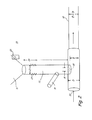
- FIG. 1 is a perspective view of one embodiment of the invention.
- FIG. 2 is a perspective view of a second embodiment of the invention.
- Feed rate controller 10 controls flow of granulated material from hopper 11 to transport tube 12, as seen in both FIG. 1 and FIG. 2 .
- the material may be any granulated material, including but not limited to powder, pellets, grit, corn, granulated crystals and the like.
- Controller 10 is particularly suited for feed rate consistency control of grit for suction blast applications.
- Hopper 11 may be closed or open, with the latter permitting addition of more material while the device is being used.
- Controller 10 includes material feed friction tube 13 that is positioned to receive material from hopper 11.
- Friction tube 13 may include an outer wall 15 in FIG. 1 to support friction tube inner wall 13.
- Friction tube 13 has a length L from the point where the granulated material enters tube 13 to the point where head pressure reduced by inter material friction, discussed below, ends.
- Friction tube 13 has a diameter C. Length L is greater than diameter C and must be sufficiently long to provide friction forces from the solid particles within friction tube 13 that is greater than the head pressure caused by material in hopper 11.
- FIG. 1 shows device 10 in a passive mode, where friction tube 13 is vented to atmospheric pressure above an orifice tube 17 having an orifice 18.
- the diameter A of orifice 18 is sized to result in smooth transport of the granulated material caused by suction air flow.
- Orifice tube 17 is held in place with set screw 21.
- Pressure above orifice tube 17 is vented to the atmosphere via vent 23 to provide the passive mode described above.
- Vent 23 may have a porous or finely perforated element of the friction tube. When hopper 11 is itself vented to atmospheric pressure, vent 23 is not required.
- the height of friction tube 13 must not only be sufficient to dissipate the head pressure caused by material in hopper 11, but also have sufficient height that the weight of material in friction tube 13 overcomes the tendency of gas pressure to lift the particles in friction tube 13.
- Orifice 18 diameter A is smaller than friction tube 13 diameter C.
- Carrier gas such as nitrogen, has a pressure P 1 and enters pickup tube 33 to transport the particles into transport tube 12.
- FIG. 2 illustrates a second embodiment in which a vibrator 25 is connected to hopper 11 to cause powder to fluidize.
- Vibrator 25 assists the powder entering the smaller vertical friction tube 13 without clumping or bridging at the entrance to friction tube 13.
- Partially down friction tube 13 is a vibration isolator 27 which stops the powder from being fluidized in friction tube 13 in order to allow frictional forces between particles and between particles and friction tube 13 walls.
- length L is the length of friction tube 13 in which friction forces interact with each other and tube 13 walls to provide the needed head pressure.
- Length 29 isolates the fluidized powder flow from friction tube 13 and is equal to or greater than the distance the granulated material requires to transition from fluidized by vibration to friction dominated flow through isolator 27.
- the powder or granulated material is subjected to a control pressure from pressure tube 31.
- the head pressure from the particles in friction tube 13 over length L is greater than the difference between control pressure in tube 31 and pressure in hopper 11.
- Orifice 18 has a diameter also sized to result in smooth transport of the granulated material at the control pressure and the desired flow rate.
- Granulated material exiting orifice 18 into pick up tube 33 does not pile up and influence the flow through the orifice because carrier gas flow rate is sufficient to prevent that from occurring.
- Carrier gas flow in transport tube 12 is greater than or equal to pickup tube 33 velocity.
- friction tube 13 length L to diameter C ratio is sufficiently high to eliminate any effect of hopper head pressure on the orifice flow rate.
- L/C > 4.
- Hopper 11 can be open, for the addition of more granulated material during operation, as long as the head pressure over length L is greater than the delta P between the control pressure in tube 31 and atmospheric pressure.
- the powder or granulated material exits as intended.
- the present invention has been found to be effective in controlling the flow of particles from a hopper to an end use, such as grit blasting of objects such as metal parts.
Landscapes
- Engineering & Computer Science (AREA)
- Mechanical Engineering (AREA)
- Air Transport Of Granular Materials (AREA)
- Filling Or Emptying Of Bunkers, Hoppers, And Tanks (AREA)
Abstract
Description
- A wide variety of materials in small particle size are transferred from hoppers to a location where the materials are to be used. Powders as small as dust or chemical powders to as large as pellets or corn, by way of example, are taken from hoppers using devices that are gravity fed to introduce the material into a gas flow for the intended use of the material.
- Feed rate control, such as for example, of grit for suction grit blast applications suffers from variability due to changing hopper loading and dust collector vacuum. Variations in these parameters cause the flow of grit through an orifice plate or into other suction pickup devices to fluctuate.
- To achieve a constant flow rate, which is highly desirable, the operator must frequently adjust orifice and suction settings. With only loose observational process feedback available to operators, these adjustments are made infrequently and somewhat arbitrarily. This makes locking down process parameters impossible.
- It is also a significant problem if the process has to be stopped in order to reload the hopper. It is also a problem if changes in pressures, flow rates, and supply volumes are adjusted arbitrarily based on observations after a change in flow has occurred.
- It would be a great advantage in suction grit blast applications if control of grit flow could be achieved to accommodate changes in the process, particularly in compensating for grit material head pressure in the grit supply.
- A device, system and method for controlling feed rate consistency in the flow of granulated materials is provided. Granulated materials are transferred from a supply hopper to a material feed friction tube. The tube has a predetermined diameter and length leading to a discharge end. The length of the tube is sufficient to provide a head pressure from the solid particles that is independent of hopper loading. When the hopper is open, which allows additional material to be added to the hopper as needed, the head pressure on the material in the friction tube is dissipated by friction between particles and the walls of the friction tube, making the pressure at the discharge end of the friction tube independent of the head pressure of the material in the hopper. The length to diameter ratio is sufficiently high to eliminate the head pressure. An effective length to diameter ratio, L/C, is equal to or greater than four.
- Material is then discharged from the tube through an orifice having a smaller diameter than the diameter of the friction tube. A pickup tube is positioned to receive material from the orifice and move the material using a source of carrier gas.
- The pickup tube has a diameter large enough to accept all the material discharged from the orifice.
- In one embodiment, the orifice diameter can be adjusted to ensure smooth transport of the solid material. A control pressure source of gas can be provided for adjusting the pressure at the orifice to approximately the pressure of the source of carrier gas in the pickup tube. Adjustment of this control pressure can be used to make changes to the particle flow rate without physical changes to the orifice. A vibrator near the bottom of the hopper can be used to help fluidize the powder and assist the powder in entry into the friction tube.
- Viewed from one aspect, the invention provides a control device for controlling flow of granulated materials from a hopper to an end use, the control device comprising a material feed friction tube positioned to receive granulated material from the hopper, the friction tube having an upper inlet end and a lower discharge end, the friction tube having a diameter and length, the length being larger than the diameter; and an orifice having a diameter and position for receiving material from the discharge end of the friction tube, the orifice being positioned to discharge material in a downward direction.
- Viewed from another aspect, the invention provides a system for controlling flow of granulated materials, comprising a granulated material supply hopper having a quantity of granulated material therein, the hopper having an opening for receiving more granulated material; a material feed friction tube positioned to receive granulated material from the hopper, the friction tube having an upper inlet end and a lower discharge end, the friction tube having a diameter and length of at least a portion of its total length, the length being larger than the diameter and sized to cause the granulated material to create a pressure from particles of granulated material rubbing against each other and the side walls of the friction tube; an orifice having a predetermined diameter and position for receiving material from the discharge end of the friction tube, the orifice being positioned to discharge material in a downward direction; and a pickup tube positioned to receive material from the orifice, the pickup tube having a diameter sized to accept all the material discharged from the orifice tube, the pickup tube further having a source of carrier gas sufficient to move the material away from the orifice.
-
FIG. 1 is a perspective view of one embodiment of the invention. -
FIG. 2 is a perspective view of a second embodiment of the invention. -
Feed rate controller 10 controls flow of granulated material fromhopper 11 totransport tube 12, as seen in bothFIG. 1 andFIG. 2 . The material may be any granulated material, including but not limited to powder, pellets, grit, corn, granulated crystals and the like.Controller 10 is particularly suited for feed rate consistency control of grit for suction blast applications. Hopper 11 may be closed or open, with the latter permitting addition of more material while the device is being used. -
Controller 10 includes materialfeed friction tube 13 that is positioned to receive material fromhopper 11.Friction tube 13 may include anouter wall 15 inFIG. 1 to support friction tubeinner wall 13.Friction tube 13 has a length L from the point where the granulated material enterstube 13 to the point where head pressure reduced by inter material friction, discussed below, ends.Friction tube 13 has a diameter C. Length L is greater than diameter C and must be sufficiently long to provide friction forces from the solid particles withinfriction tube 13 that is greater than the head pressure caused by material inhopper 11.Friction tube 13 negates the head pressure fromhopper 11 by the friction forces when the particles of granulated materials rub against the side walls offriction tube 13 and against each other.Friction tube 13 length L to diameter C ratio is sufficiently high to eliminate any effect of head pressure on the orifice flow rate. Thus L/C >= 4. - At the bottom of
friction tube 13, orifice tube orplate 17 is positioned to receive material from thedischarge end 19 offriction tube 13.FIG. 1 showsdevice 10 in a passive mode, wherefriction tube 13 is vented to atmospheric pressure above anorifice tube 17 having anorifice 18. The diameter A oforifice 18 is sized to result in smooth transport of the granulated material caused by suction air flow. Orificetube 17 is held in place with setscrew 21. Pressure aboveorifice tube 17 is vented to the atmosphere viavent 23 to provide the passive mode described above.Vent 23 may have a porous or finely perforated element of the friction tube. Whenhopper 11 is itself vented to atmospheric pressure,vent 23 is not required. Whenhopper 11 is fitted with a vacuum driven automatic loading device or any other device that causes a variation in pressure withinhopper 11, the height offriction tube 13 must not only be sufficient to dissipate the head pressure caused by material inhopper 11, but also have sufficient height that the weight of material infriction tube 13 overcomes the tendency of gas pressure to lift the particles infriction tube 13. - Particles
exit friction tube 13 intoorifice tube 17 and are controlled so that flow of particles is maintained regardless of the quantity of particles inhopper 11. Orifice 18 diameter A is smaller thanfriction tube 13 diameter C. Particles flow down into pick uptube 33, which has a diameter D that is larger than material height B in order to start airflow without clogging. - Height B is high enough to prevent material from piling up and influencing flow through
orifice 18. Carrier gas, such as nitrogen, has a pressure P1 and enterspickup tube 33 to transport the particles intotransport tube 12. -
FIG. 2 illustrates a second embodiment in which avibrator 25 is connected to hopper 11 to cause powder to fluidize.Vibrator 25 assists the powder entering the smallervertical friction tube 13 without clumping or bridging at the entrance tofriction tube 13. Partially downfriction tube 13 is avibration isolator 27 which stops the powder from being fluidized infriction tube 13 in order to allow frictional forces between particles and between particles andfriction tube 13 walls. Thus length L is the length offriction tube 13 in which friction forces interact with each other andtube 13 walls to provide the needed head pressure.Length 29 isolates the fluidized powder flow fromfriction tube 13 and is equal to or greater than the distance the granulated material requires to transition from fluidized by vibration to friction dominated flow throughisolator 27. - In
FIG. 2 , the powder or granulated material is subjected to a control pressure frompressure tube 31. The head pressure from the particles infriction tube 13 over length L is greater than the difference between control pressure intube 31 and pressure inhopper 11. Orifice 18 has a diameter also sized to result in smooth transport of the granulated material at the control pressure and the desired flow rate. - Granulated
material exiting orifice 18 into pick uptube 33 does not pile up and influence the flow through the orifice because carrier gas flow rate is sufficient to prevent that from occurring. Carrier gas flow intransport tube 12 is greater than or equal topickup tube 33 velocity. Again,friction tube 13 length L to diameter C ratio is sufficiently high to eliminate any effect of hopper head pressure on the orifice flow rate. Thus L/C >= 4. -
Hopper 11 can be open, for the addition of more granulated material during operation, as long as the head pressure over length L is greater than the delta P between the control pressure intube 31 and atmospheric pressure. - When carrier gas flow is stopped, granulated material exits
orifice 18 into pick uptube 33 and piles up to stop the flow through the orifice. Flow can then be re-established by resuming gas flow. This can be achieved smoothly by maintaining height B at a sufficiently small fraction of the diameter of pickup tube diameter D to allow the initiation of gas flow around the piled up granular material. - In both embodiments, the powder or granulated material exits as intended. The present invention has been found to be effective in controlling the flow of particles from a hopper to an end use, such as grit blasting of objects such as metal parts.
- While the invention has been described with reference to an exemplary embodiment(s), it will be understood by those skilled in the art that various changes may be made and equivalents may be substituted for elements thereof without departing from the scope of the invention. In addition, many modifications may be made to adapt a particular situation or material to the teachings of the invention without departing from the essential scope thereof. Therefore, it is intended that the invention not be limited to the particular embodiment(s) disclosed, but that the invention will include all embodiments falling within the scope of the appended claims.
Claims (15)
- A control device for controlling flow of granulated materials from a hopper to an end use, the control device comprising:a material feed friction tube positionable to receive granulated material from the hopper, the friction tube having an upper inlet end and a lower discharge end, the friction tube having a diameter and length, the length being larger than the diameter and sized to cause the head pressure from the granulated material in the hopper to be dissipated by particles of granulated material rubbing against each other and the side walls of the friction tube; andan orifice having a diameter and position for receiving material from the discharge end of the friction tube, the orifice being positioned to discharge material in a downward direction.
- The control device of claim 1, which further includes a pickup tube positioned to receive material from the orifice for receiving material from the friction tube, the pickup tube having a source of carrier gas sufficient to move the material.
- The control device of claim 2, wherein the pickup tube has a gas flow rate and a diameter sized to prevent granulated material from piling up when discharged from the orifice.
- The control device of claim 3, wherein the transport tube has a diameter less than the diameter of the pickup tube.
- The control device of claim 1, 2, 3 or 4, including a vibrator positioned proximate the inlet of the material feed friction tube from the supply hopper to cause granulated material to enter the friction tube as fluidized particles, and a vibration isolator adapted to isolate the fluidized particles from a portion of the friction tube to cause the material to have frictional forces between the material and the wall of the material feed friction tube, the portion of the friction tube having frictional forces being of sufficient length to cause the granulated material to dissipate head pressure from particles of granulated material rubbing against each other and the side walls of the friction tube.
- The control device of any preceding claim, wherein the material feed friction tube includes a control pressure source of gas for adjusting the pressure at the orifice to approximate the pressure of the source of carrier gas in the pickup tube.
- A system for controlling flow of granulated materials, comprising:a granulated material supply hopper for receiving a quantity of granulated material therein, the hopper having an opening for receiving more granulated material;and a control device as claimed in any preceding claim comprising a material feed friction tube positioned to receive granulated material from the hopper, the friction tube having an upper inlet end and a lower discharge end, the friction tube having a diameter and length of at least a portion of its total length, the length being larger than the diameter and sized to cause the granulated material to create a pressure from particles of granulated material rubbing against each other and the side walls of the friction tube, and an orifice having a predetermined diameter and position for receiving material from the discharge end of the friction tube, the orifice being positioned to discharge material in a downward direction; anda pickup tube positioned to receive material from the orifice, the pickup tube having a diameter sized to accept all the material discharged from the orifice tube, the pickup tube further having a source of carrier gas sufficient to move the material away from the orifice.
- The system of claim 7, wherein the height of the friction tube is sufficient to dissipate the head pressure caused by material in the hopper and also of sufficient height that the weight of material in friction tube overcomes the tendency of gas pressure to lift the particles in the friction tube.
- The system of claim 7 or 8, wherein the pickup tube has a diameter sized to prevent granulated material from piling up when discharged from the orifice.
- The system of claim 7, 8 or 9, wherein the orifice has a diameter less than the diameter of the pickup tube.
- A method for controlling the flow of granulated materials, comprising:supplying a granulated material in a supply hopper;delivering material from the hopper into an inlet at an upper end of a material feed friction tube positioned to receive material from the hopper;discharging material from an orifice at the lower end of the friction tube into a pickup tube positioned to receive material from the orifice; andtransferring the material from the pickup tube using a source of carrier gas sufficient to move the material for further use.
- The method of claim 11, wherein the orifice is formed in a tube positioned in the friction tube.
- The method of claim 11 or 12, wherein the height of the friction tube is sufficient to dissipate the head pressure caused by material in the hopper and also of sufficient height that the weight of material in friction tube overcomes the tendency of gas pressure to lift the particles in the friction tube; and/or
wherein the pickup tube has a diameter sized to prevent granulated material from piling up when discharged from the orifice; and/or
wherein the orifice includes a device for adjusting the orifice diameter. - The method of claim 11, 12 or 13, wherein the material feed friction tube includes a controlled pressure source of gas for adjusting the pressure at the orifice; preferably
wherein the controlled pressure source of gas is introduced at an angle with respect to the direction of material flow in the material feed friction tube through a porous or finely perforated element of the friction tube. - The method of claim 11, 12, 13 or 14, wherein a vibrator is positioned proximate the inlet of the material feed friction tube from the supply hopper to cause granulated material to enter the friction tube as fluidized particles, the vibrator further being adapted to isolate the fluidized particles in the friction tube to cause the material to have frictional forces between the material and the material feed friction tube, the portion of the friction tube having frictional forces being of sufficient length to cause the granulated material to create a pressure from particles of granulated material rubbing against each other and the friction tube; preferably
wherein the orifice is positioned at a bottom of the friction tube.
Applications Claiming Priority (1)
| Application Number | Priority Date | Filing Date | Title |
|---|---|---|---|
| US13/355,616 US20130186920A1 (en) | 2012-01-23 | 2012-01-23 | Feed rate controller for granulated materials |
Publications (2)
| Publication Number | Publication Date |
|---|---|
| EP2617524A1 true EP2617524A1 (en) | 2013-07-24 |
| EP2617524B1 EP2617524B1 (en) | 2015-09-16 |
Family
ID=47632846
Family Applications (1)
| Application Number | Title | Priority Date | Filing Date |
|---|---|---|---|
| EP13152438.1A Active EP2617524B1 (en) | 2012-01-23 | 2013-01-23 | Feed rate controller for granulated materials |
Country Status (2)
| Country | Link |
|---|---|
| US (1) | US20130186920A1 (en) |
| EP (1) | EP2617524B1 (en) |
Families Citing this family (3)
| Publication number | Priority date | Publication date | Assignee | Title |
|---|---|---|---|---|
| US20160217974A1 (en) * | 2015-01-28 | 2016-07-28 | Stephen J. Motosko | Apparatus for plasma treating |
| ITRE20150027A1 (en) * | 2015-04-15 | 2016-10-15 | Moretti Mattia | PORTABLE DIFFUSER FOR THE LAUNCH OF GRANULOUS MATERIAL IN PLANT HEALTH TREATMENTS, IN PARTICULAR BIOLOGICAL. |
| US20250269962A1 (en) * | 2024-02-23 | 2025-08-28 | Universal City Studios Llc | Flame effect system for an unmanned aerial vehicle |
Citations (1)
| Publication number | Priority date | Publication date | Assignee | Title |
|---|---|---|---|---|
| WO1995008407A1 (en) * | 1993-09-21 | 1995-03-30 | Tomco2 Equipment Company | Sublimable particle blast cleaning apparatus |
Family Cites Families (17)
| Publication number | Priority date | Publication date | Assignee | Title |
|---|---|---|---|---|
| US3078015A (en) * | 1960-03-03 | 1963-02-19 | Eugene A Wahl | Vibrated hopper or storage bin |
| US3201901A (en) * | 1963-09-30 | 1965-08-24 | Alfred M Pauli | Abrasive blasting equipment |
| US3304647A (en) * | 1964-10-02 | 1967-02-21 | Szekely George | Duster devices |
| US3297203A (en) * | 1965-04-26 | 1967-01-10 | Eugene A Wahl | Material feeder |
| US3415450A (en) * | 1966-05-24 | 1968-12-10 | Coast Metals Inc | Powder supply construction for spray torch |
| US3807602A (en) * | 1972-07-10 | 1974-04-30 | Thyssen Huette Ag | Method and apparatus for dispensing a fluidizable solid from a pressure vessel |
| US4655847A (en) * | 1983-09-01 | 1987-04-07 | Tsuyoshi Ichinoseki | Cleaning method |
| JPS6067077A (en) * | 1983-09-19 | 1985-04-17 | Ishikawajima Harima Heavy Ind Co Ltd | Method and device for cleaning objects to be polished |
| US4617064A (en) * | 1984-07-31 | 1986-10-14 | Cryoblast, Inc. | Cleaning method and apparatus |
| US4744181A (en) * | 1986-11-17 | 1988-05-17 | Moore David E | Particle-blast cleaning apparatus and method |
| US5081799A (en) * | 1990-04-06 | 1992-01-21 | Church & Dwight Co., Inc. | Blasting apparatus |
| WO1992022488A1 (en) * | 1991-06-17 | 1992-12-23 | Acrison, Inc. | Dry solids materials feeder with vibratory mechanism and a method of vibrating various component parts of the feeder |
| US5405049A (en) * | 1993-10-27 | 1995-04-11 | Acrison, Inc. | Isolation pad for a feeding system and a method for feeding material from the system |
| US5582718A (en) * | 1994-06-14 | 1996-12-10 | Sobczak; Donald J. | Non-pressurized algaecide feeder method and apparatus for swimming pools and the like |
| US5704280A (en) * | 1995-12-04 | 1998-01-06 | Walker Stainless Equipment Company, Inc. | Food processing device |
| US7475793B2 (en) * | 2005-01-07 | 2009-01-13 | Wahl Richard C | Bulk bag unloader with flow regulation |
| TW200942639A (en) * | 2007-12-07 | 2009-10-16 | Jusung Eng Co Ltd | Deposition material supplying module and thin film deposition system having the same |
-
2012
- 2012-01-23 US US13/355,616 patent/US20130186920A1/en not_active Abandoned
-
2013
- 2013-01-23 EP EP13152438.1A patent/EP2617524B1/en active Active
Patent Citations (1)
| Publication number | Priority date | Publication date | Assignee | Title |
|---|---|---|---|---|
| WO1995008407A1 (en) * | 1993-09-21 | 1995-03-30 | Tomco2 Equipment Company | Sublimable particle blast cleaning apparatus |
Also Published As
| Publication number | Publication date |
|---|---|
| US20130186920A1 (en) | 2013-07-25 |
| EP2617524B1 (en) | 2015-09-16 |
Similar Documents
| Publication | Publication Date | Title |
|---|---|---|
| US6354465B2 (en) | Protable device for accurately metering and delivering cohesive bulk solid powders | |
| US3504945A (en) | Pneumatic conveyor system | |
| US5478172A (en) | Apparatus for feeding ultrafine powder in quantitative batch operation | |
| CA1041056A (en) | Powder feeder pick-up tube | |
| KR101576653B1 (en) | Feeding apparatus using vibration or impact of granule or micropowder | |
| EP2617524B1 (en) | Feed rate controller for granulated materials | |
| US10179696B2 (en) | Variable opening slide gate for regulating material flow into airstream | |
| EP3375716B1 (en) | Toner filling apparatus | |
| CN115485220B (en) | Powder and particle supply device | |
| JP5985155B2 (en) | Powder quantitative supply method | |
| CN218289632U (en) | Silo is with fixed many chutes formula distributing device | |
| CN109573623A (en) | The feed proportioning system and its working method of solid pharmaceutical preparation | |
| UA120708C2 (en) | Method for equalizing the gas pressure in a hopper and hopper | |
| KR20200053853A (en) | Hopper and device for transferring of powder having the same | |
| US6276516B1 (en) | Flow control device | |
| CN105764617B (en) | Binder buffer unit, associated filling system and method of storing and moving binder particles | |
| JP4646593B2 (en) | Apparatus and method for conveying hot melt adhesive | |
| CN110325343B (en) | Additive manufacturing method using a conveyor for conveying articles by positive pressure | |
| EP1079214A2 (en) | Vibratory feeder | |
| CN212314956U (en) | Weighing feeding device and material processing system | |
| EP3882185B1 (en) | Pumping apparatus | |
| JP2018167975A (en) | Powder supply system | |
| CN222699552U (en) | A vibrating feeder | |
| JP2009166968A (en) | Particulate dispensing device | |
| US20250381538A1 (en) | Apparatus for mixing and/or conditioning powdery materials and method of operating the same |
Legal Events
| Date | Code | Title | Description |
|---|---|---|---|
| PUAI | Public reference made under article 153(3) epc to a published international application that has entered the european phase |
Free format text: ORIGINAL CODE: 0009012 |
|
| AK | Designated contracting states |
Kind code of ref document: A1 Designated state(s): AL AT BE BG CH CY CZ DE DK EE ES FI FR GB GR HR HU IE IS IT LI LT LU LV MC MK MT NL NO PL PT RO RS SE SI SK SM TR |
|
| AX | Request for extension of the european patent |
Extension state: BA ME |
|
| 17P | Request for examination filed |
Effective date: 20140124 |
|
| RBV | Designated contracting states (corrected) |
Designated state(s): AL AT BE BG CH CY CZ DE DK EE ES FI FR GB GR HR HU IE IS IT LI LT LU LV MC MK MT NL NO PL PT RO RS SE SI SK SM TR |
|
| RIC1 | Information provided on ipc code assigned before grant |
Ipc: B24C 7/00 20060101AFI20150302BHEP |
|
| GRAP | Despatch of communication of intention to grant a patent |
Free format text: ORIGINAL CODE: EPIDOSNIGR1 |
|
| GRAJ | Information related to disapproval of communication of intention to grant by the applicant or resumption of examination proceedings by the epo deleted |
Free format text: ORIGINAL CODE: EPIDOSDIGR1 |
|
| GRAP | Despatch of communication of intention to grant a patent |
Free format text: ORIGINAL CODE: EPIDOSNIGR1 |
|
| INTG | Intention to grant announced |
Effective date: 20150414 |
|
| INTG | Intention to grant announced |
Effective date: 20150423 |
|
| GRAS | Grant fee paid |
Free format text: ORIGINAL CODE: EPIDOSNIGR3 |
|
| GRAA | (expected) grant |
Free format text: ORIGINAL CODE: 0009210 |
|
| AK | Designated contracting states |
Kind code of ref document: B1 Designated state(s): AL AT BE BG CH CY CZ DE DK EE ES FI FR GB GR HR HU IE IS IT LI LT LU LV MC MK MT NL NO PL PT RO RS SE SI SK SM TR |
|
| REG | Reference to a national code |
Ref country code: GB Ref legal event code: FG4D |
|
| REG | Reference to a national code |
Ref country code: CH Ref legal event code: EP |
|
| REG | Reference to a national code |
Ref country code: IE Ref legal event code: FG4D |
|
| REG | Reference to a national code |
Ref country code: AT Ref legal event code: REF Ref document number: 749409 Country of ref document: AT Kind code of ref document: T Effective date: 20151015 |
|
| REG | Reference to a national code |
Ref country code: DE Ref legal event code: R096 Ref document number: 602013002980 Country of ref document: DE |
|
| REG | Reference to a national code |
Ref country code: NL Ref legal event code: MP Effective date: 20150916 |
|
| PG25 | Lapsed in a contracting state [announced via postgrant information from national office to epo] |
Ref country code: LT Free format text: LAPSE BECAUSE OF FAILURE TO SUBMIT A TRANSLATION OF THE DESCRIPTION OR TO PAY THE FEE WITHIN THE PRESCRIBED TIME-LIMIT Effective date: 20150916 Ref country code: NO Free format text: LAPSE BECAUSE OF FAILURE TO SUBMIT A TRANSLATION OF THE DESCRIPTION OR TO PAY THE FEE WITHIN THE PRESCRIBED TIME-LIMIT Effective date: 20151216 Ref country code: GR Free format text: LAPSE BECAUSE OF FAILURE TO SUBMIT A TRANSLATION OF THE DESCRIPTION OR TO PAY THE FEE WITHIN THE PRESCRIBED TIME-LIMIT Effective date: 20151217 Ref country code: FI Free format text: LAPSE BECAUSE OF FAILURE TO SUBMIT A TRANSLATION OF THE DESCRIPTION OR TO PAY THE FEE WITHIN THE PRESCRIBED TIME-LIMIT Effective date: 20150916 Ref country code: LV Free format text: LAPSE BECAUSE OF FAILURE TO SUBMIT A TRANSLATION OF THE DESCRIPTION OR TO PAY THE FEE WITHIN THE PRESCRIBED TIME-LIMIT Effective date: 20150916 |
|
| REG | Reference to a national code |
Ref country code: LT Ref legal event code: MG4D |
|
| REG | Reference to a national code |
Ref country code: AT Ref legal event code: MK05 Ref document number: 749409 Country of ref document: AT Kind code of ref document: T Effective date: 20150916 |
|
| PG25 | Lapsed in a contracting state [announced via postgrant information from national office to epo] |
Ref country code: SE Free format text: LAPSE BECAUSE OF FAILURE TO SUBMIT A TRANSLATION OF THE DESCRIPTION OR TO PAY THE FEE WITHIN THE PRESCRIBED TIME-LIMIT Effective date: 20150916 Ref country code: HR Free format text: LAPSE BECAUSE OF FAILURE TO SUBMIT A TRANSLATION OF THE DESCRIPTION OR TO PAY THE FEE WITHIN THE PRESCRIBED TIME-LIMIT Effective date: 20150916 Ref country code: RS Free format text: LAPSE BECAUSE OF FAILURE TO SUBMIT A TRANSLATION OF THE DESCRIPTION OR TO PAY THE FEE WITHIN THE PRESCRIBED TIME-LIMIT Effective date: 20150916 |
|
| PG25 | Lapsed in a contracting state [announced via postgrant information from national office to epo] |
Ref country code: NL Free format text: LAPSE BECAUSE OF FAILURE TO SUBMIT A TRANSLATION OF THE DESCRIPTION OR TO PAY THE FEE WITHIN THE PRESCRIBED TIME-LIMIT Effective date: 20150916 |
|
| PG25 | Lapsed in a contracting state [announced via postgrant information from national office to epo] |
Ref country code: IS Free format text: LAPSE BECAUSE OF FAILURE TO SUBMIT A TRANSLATION OF THE DESCRIPTION OR TO PAY THE FEE WITHIN THE PRESCRIBED TIME-LIMIT Effective date: 20160116 Ref country code: ES Free format text: LAPSE BECAUSE OF FAILURE TO SUBMIT A TRANSLATION OF THE DESCRIPTION OR TO PAY THE FEE WITHIN THE PRESCRIBED TIME-LIMIT Effective date: 20150916 Ref country code: CZ Free format text: LAPSE BECAUSE OF FAILURE TO SUBMIT A TRANSLATION OF THE DESCRIPTION OR TO PAY THE FEE WITHIN THE PRESCRIBED TIME-LIMIT Effective date: 20150916 Ref country code: IT Free format text: LAPSE BECAUSE OF FAILURE TO SUBMIT A TRANSLATION OF THE DESCRIPTION OR TO PAY THE FEE WITHIN THE PRESCRIBED TIME-LIMIT Effective date: 20150916 Ref country code: SK Free format text: LAPSE BECAUSE OF FAILURE TO SUBMIT A TRANSLATION OF THE DESCRIPTION OR TO PAY THE FEE WITHIN THE PRESCRIBED TIME-LIMIT Effective date: 20150916 Ref country code: EE Free format text: LAPSE BECAUSE OF FAILURE TO SUBMIT A TRANSLATION OF THE DESCRIPTION OR TO PAY THE FEE WITHIN THE PRESCRIBED TIME-LIMIT Effective date: 20150916 |
|
| PG25 | Lapsed in a contracting state [announced via postgrant information from national office to epo] |
Ref country code: AT Free format text: LAPSE BECAUSE OF FAILURE TO SUBMIT A TRANSLATION OF THE DESCRIPTION OR TO PAY THE FEE WITHIN THE PRESCRIBED TIME-LIMIT Effective date: 20150916 Ref country code: BE Free format text: LAPSE BECAUSE OF NON-PAYMENT OF DUE FEES Effective date: 20160131 Ref country code: PT Free format text: LAPSE BECAUSE OF FAILURE TO SUBMIT A TRANSLATION OF THE DESCRIPTION OR TO PAY THE FEE WITHIN THE PRESCRIBED TIME-LIMIT Effective date: 20160118 Ref country code: PL Free format text: LAPSE BECAUSE OF FAILURE TO SUBMIT A TRANSLATION OF THE DESCRIPTION OR TO PAY THE FEE WITHIN THE PRESCRIBED TIME-LIMIT Effective date: 20150916 Ref country code: RO Free format text: LAPSE BECAUSE OF FAILURE TO SUBMIT A TRANSLATION OF THE DESCRIPTION OR TO PAY THE FEE WITHIN THE PRESCRIBED TIME-LIMIT Effective date: 20150916 |
|
| REG | Reference to a national code |
Ref country code: DE Ref legal event code: R097 Ref document number: 602013002980 Country of ref document: DE |
|
| PLBE | No opposition filed within time limit |
Free format text: ORIGINAL CODE: 0009261 |
|
| STAA | Information on the status of an ep patent application or granted ep patent |
Free format text: STATUS: NO OPPOSITION FILED WITHIN TIME LIMIT |
|
| 26N | No opposition filed |
Effective date: 20160617 |
|
| PG25 | Lapsed in a contracting state [announced via postgrant information from national office to epo] |
Ref country code: LU Free format text: LAPSE BECAUSE OF FAILURE TO SUBMIT A TRANSLATION OF THE DESCRIPTION OR TO PAY THE FEE WITHIN THE PRESCRIBED TIME-LIMIT Effective date: 20160123 Ref country code: DK Free format text: LAPSE BECAUSE OF FAILURE TO SUBMIT A TRANSLATION OF THE DESCRIPTION OR TO PAY THE FEE WITHIN THE PRESCRIBED TIME-LIMIT Effective date: 20150916 |
|
| REG | Reference to a national code |
Ref country code: CH Ref legal event code: PL |
|
| PG25 | Lapsed in a contracting state [announced via postgrant information from national office to epo] |
Ref country code: MC Free format text: LAPSE BECAUSE OF FAILURE TO SUBMIT A TRANSLATION OF THE DESCRIPTION OR TO PAY THE FEE WITHIN THE PRESCRIBED TIME-LIMIT Effective date: 20150916 |
|
| REG | Reference to a national code |
Ref country code: FR Ref legal event code: ST Effective date: 20160930 |
|
| PG25 | Lapsed in a contracting state [announced via postgrant information from national office to epo] |
Ref country code: CH Free format text: LAPSE BECAUSE OF NON-PAYMENT OF DUE FEES Effective date: 20160131 Ref country code: LI Free format text: LAPSE BECAUSE OF NON-PAYMENT OF DUE FEES Effective date: 20160131 |
|
| REG | Reference to a national code |
Ref country code: IE Ref legal event code: MM4A |
|
| PG25 | Lapsed in a contracting state [announced via postgrant information from national office to epo] |
Ref country code: FR Free format text: LAPSE BECAUSE OF NON-PAYMENT OF DUE FEES Effective date: 20160201 Ref country code: SI Free format text: LAPSE BECAUSE OF FAILURE TO SUBMIT A TRANSLATION OF THE DESCRIPTION OR TO PAY THE FEE WITHIN THE PRESCRIBED TIME-LIMIT Effective date: 20150916 |
|
| PG25 | Lapsed in a contracting state [announced via postgrant information from national office to epo] |
Ref country code: BE Free format text: LAPSE BECAUSE OF FAILURE TO SUBMIT A TRANSLATION OF THE DESCRIPTION OR TO PAY THE FEE WITHIN THE PRESCRIBED TIME-LIMIT Effective date: 20150916 |
|
| PG25 | Lapsed in a contracting state [announced via postgrant information from national office to epo] |
Ref country code: IE Free format text: LAPSE BECAUSE OF NON-PAYMENT OF DUE FEES Effective date: 20160123 |
|
| REG | Reference to a national code |
Ref country code: DE Ref legal event code: R082 Ref document number: 602013002980 Country of ref document: DE Representative=s name: SCHMITT-NILSON SCHRAUD WAIBEL WOHLFROM PATENTA, DE |
|
| REG | Reference to a national code |
Ref country code: DE Ref legal event code: R082 Ref document number: 602013002980 Country of ref document: DE Representative=s name: SCHMITT-NILSON SCHRAUD WAIBEL WOHLFROM PATENTA, DE Ref country code: DE Ref legal event code: R081 Ref document number: 602013002980 Country of ref document: DE Owner name: UNITED TECHNOLOGIES CORP. (N.D.GES.D. STAATES , US Free format text: FORMER OWNER: UNITED TECHNOLOGIES CORP., HARTFORD, CONN., US |
|
| PG25 | Lapsed in a contracting state [announced via postgrant information from national office to epo] |
Ref country code: MT Free format text: LAPSE BECAUSE OF FAILURE TO SUBMIT A TRANSLATION OF THE DESCRIPTION OR TO PAY THE FEE WITHIN THE PRESCRIBED TIME-LIMIT Effective date: 20150916 |
|
| PG25 | Lapsed in a contracting state [announced via postgrant information from national office to epo] |
Ref country code: SM Free format text: LAPSE BECAUSE OF FAILURE TO SUBMIT A TRANSLATION OF THE DESCRIPTION OR TO PAY THE FEE WITHIN THE PRESCRIBED TIME-LIMIT Effective date: 20150916 Ref country code: CY Free format text: LAPSE BECAUSE OF FAILURE TO SUBMIT A TRANSLATION OF THE DESCRIPTION OR TO PAY THE FEE WITHIN THE PRESCRIBED TIME-LIMIT Effective date: 20150916 Ref country code: HU Free format text: LAPSE BECAUSE OF FAILURE TO SUBMIT A TRANSLATION OF THE DESCRIPTION OR TO PAY THE FEE WITHIN THE PRESCRIBED TIME-LIMIT; INVALID AB INITIO Effective date: 20130123 |
|
| PG25 | Lapsed in a contracting state [announced via postgrant information from national office to epo] |
Ref country code: MK Free format text: LAPSE BECAUSE OF FAILURE TO SUBMIT A TRANSLATION OF THE DESCRIPTION OR TO PAY THE FEE WITHIN THE PRESCRIBED TIME-LIMIT Effective date: 20150916 Ref country code: TR Free format text: LAPSE BECAUSE OF FAILURE TO SUBMIT A TRANSLATION OF THE DESCRIPTION OR TO PAY THE FEE WITHIN THE PRESCRIBED TIME-LIMIT Effective date: 20150916 Ref country code: MT Free format text: LAPSE BECAUSE OF FAILURE TO SUBMIT A TRANSLATION OF THE DESCRIPTION OR TO PAY THE FEE WITHIN THE PRESCRIBED TIME-LIMIT Effective date: 20160131 |
|
| PG25 | Lapsed in a contracting state [announced via postgrant information from national office to epo] |
Ref country code: BG Free format text: LAPSE BECAUSE OF FAILURE TO SUBMIT A TRANSLATION OF THE DESCRIPTION OR TO PAY THE FEE WITHIN THE PRESCRIBED TIME-LIMIT Effective date: 20150916 |
|
| PG25 | Lapsed in a contracting state [announced via postgrant information from national office to epo] |
Ref country code: AL Free format text: LAPSE BECAUSE OF FAILURE TO SUBMIT A TRANSLATION OF THE DESCRIPTION OR TO PAY THE FEE WITHIN THE PRESCRIBED TIME-LIMIT Effective date: 20150916 |
|
| REG | Reference to a national code |
Ref country code: DE Ref legal event code: R081 Ref document number: 602013002980 Country of ref document: DE Owner name: RAYTHEON TECHNOLOGIES CORPORATION (N.D.GES.D.S, US Free format text: FORMER OWNER: UNITED TECHNOLOGIES CORP. (N.D.GES.D. STAATES DELAWARE), FARMINGTON, CONN., US Ref country code: DE Ref legal event code: R081 Ref document number: 602013002980 Country of ref document: DE Owner name: RTX CORPORATION (N.D.GES.D. STAATES DELAWARE),, US Free format text: FORMER OWNER: UNITED TECHNOLOGIES CORP. (N.D.GES.D. STAATES DELAWARE), FARMINGTON, CONN., US |
|
| P01 | Opt-out of the competence of the unified patent court (upc) registered |
Effective date: 20230520 |
|
| REG | Reference to a national code |
Ref country code: DE Ref legal event code: R081 Ref document number: 602013002980 Country of ref document: DE Owner name: RTX CORPORATION (N.D.GES.D. STAATES DELAWARE),, US Free format text: FORMER OWNER: RAYTHEON TECHNOLOGIES CORPORATION (N.D.GES.D.STAATES DELAWARE), ARLINGTON, VA, US |
|
| PGFP | Annual fee paid to national office [announced via postgrant information from national office to epo] |
Ref country code: GB Payment date: 20251219 Year of fee payment: 14 |
|
| PGFP | Annual fee paid to national office [announced via postgrant information from national office to epo] |
Ref country code: DE Payment date: 20251217 Year of fee payment: 14 |