EP2617376A1 - Bone resection jig used in surgical operation to replace artificial knee joint - Google Patents
Bone resection jig used in surgical operation to replace artificial knee joint Download PDFInfo
- Publication number
- EP2617376A1 EP2617376A1 EP11825296.4A EP11825296A EP2617376A1 EP 2617376 A1 EP2617376 A1 EP 2617376A1 EP 11825296 A EP11825296 A EP 11825296A EP 2617376 A1 EP2617376 A1 EP 2617376A1
- Authority
- EP
- European Patent Office
- Prior art keywords
- femur
- distal end
- resection
- tibia
- knee joint
- Prior art date
- Legal status (The legal status is an assumption and is not a legal conclusion. Google has not performed a legal analysis and makes no representation as to the accuracy of the status listed.)
- Granted
Links
Images




Classifications
-
- A—HUMAN NECESSITIES
- A61—MEDICAL OR VETERINARY SCIENCE; HYGIENE
- A61B—DIAGNOSIS; SURGERY; IDENTIFICATION
- A61B17/00—Surgical instruments, devices or methods
- A61B17/16—Instruments for performing osteoclasis; Drills or chisels for bones; Trepans
- A61B17/17—Guides or aligning means for drills, mills, pins or wires
- A61B17/1739—Guides or aligning means for drills, mills, pins or wires specially adapted for particular parts of the body
- A61B17/1764—Guides or aligning means for drills, mills, pins or wires specially adapted for particular parts of the body for the knee
-
- A—HUMAN NECESSITIES
- A61—MEDICAL OR VETERINARY SCIENCE; HYGIENE
- A61B—DIAGNOSIS; SURGERY; IDENTIFICATION
- A61B17/00—Surgical instruments, devices or methods
- A61B17/02—Surgical instruments, devices or methods for holding wounds open, e.g. retractors; Tractors
- A61B17/025—Joint distractors
-
- A—HUMAN NECESSITIES
- A61—MEDICAL OR VETERINARY SCIENCE; HYGIENE
- A61B—DIAGNOSIS; SURGERY; IDENTIFICATION
- A61B17/00—Surgical instruments, devices or methods
- A61B17/14—Surgical saws
- A61B17/15—Guides therefor
- A61B17/154—Guides therefor for preparing bone for knee prosthesis
- A61B17/155—Cutting femur
-
- A—HUMAN NECESSITIES
- A61—MEDICAL OR VETERINARY SCIENCE; HYGIENE
- A61F—FILTERS IMPLANTABLE INTO BLOOD VESSELS; PROSTHESES; DEVICES PROVIDING PATENCY TO, OR PREVENTING COLLAPSING OF, TUBULAR STRUCTURES OF THE BODY, e.g. STENTS; ORTHOPAEDIC, NURSING OR CONTRACEPTIVE DEVICES; FOMENTATION; TREATMENT OR PROTECTION OF EYES OR EARS; BANDAGES, DRESSINGS OR ABSORBENT PADS; FIRST-AID KITS
- A61F2/00—Filters implantable into blood vessels; Prostheses, i.e. artificial substitutes or replacements for parts of the body; Appliances for connecting them with the body; Devices providing patency to, or preventing collapsing of, tubular structures of the body, e.g. stents
- A61F2/02—Prostheses implantable into the body
- A61F2/30—Joints
- A61F2/46—Special tools for implanting artificial joints
- A61F2/4684—Trial or dummy prostheses
-
- A—HUMAN NECESSITIES
- A61—MEDICAL OR VETERINARY SCIENCE; HYGIENE
- A61B—DIAGNOSIS; SURGERY; IDENTIFICATION
- A61B17/00—Surgical instruments, devices or methods
- A61B17/02—Surgical instruments, devices or methods for holding wounds open, e.g. retractors; Tractors
- A61B17/025—Joint distractors
- A61B2017/0268—Joint distractors for the knee
-
- A—HUMAN NECESSITIES
- A61—MEDICAL OR VETERINARY SCIENCE; HYGIENE
- A61F—FILTERS IMPLANTABLE INTO BLOOD VESSELS; PROSTHESES; DEVICES PROVIDING PATENCY TO, OR PREVENTING COLLAPSING OF, TUBULAR STRUCTURES OF THE BODY, e.g. STENTS; ORTHOPAEDIC, NURSING OR CONTRACEPTIVE DEVICES; FOMENTATION; TREATMENT OR PROTECTION OF EYES OR EARS; BANDAGES, DRESSINGS OR ABSORBENT PADS; FIRST-AID KITS
- A61F2/00—Filters implantable into blood vessels; Prostheses, i.e. artificial substitutes or replacements for parts of the body; Appliances for connecting them with the body; Devices providing patency to, or preventing collapsing of, tubular structures of the body, e.g. stents
- A61F2/02—Prostheses implantable into the body
- A61F2/30—Joints
- A61F2/38—Joints for elbows or knees
- A61F2/389—Tibial components
Definitions
- the present invention relates to a bone resection jig used during artifcial knee joint replacement surgery.
- This artificial knee joint comprises a combination of a femur component, which has two condyles of medial and lateral, and a tibia component, which has a joint plate that bears these two condyles and allows them to rotate; and it is desirous that artificial knee joints that are comprised of such condyles and joint plates preferably be movable similarly to a biogenic knee joint.
- Patent Literature 1 listed below, proposes a bone resection jig that sets a bone resection range after confirming that tension is the same in the extension position and in the flexion position.
- the invention of this prior art checks (measures) the tension of ligaments in both extension and flexion positions; accordingly, the operation is troublesome, and it requires a longer surgical time. Further, the constitution is complex, and it includes many moving parts and adjustment parts, and further it requires numerous operation steps that are difficult and require proficiency. In addition, it is heavy and expensive.
- Patent Literature I Patent Application Laid-Open (Kokai) 2007-75517
- the present invention proposes a bone resection jig based on the principle that the same tension can be derived in ligaments at the extension position and flexion position if the bone resection range (interval) is the same at both positions, and it provides a bone resection jig which is extremely simple in constitution and inexpensive. Furthermore, the present invention provides a bone resection jig that does not require proficiency to operate, can shorten surgery time, and reduces the impact on a patient.
- the present invention is to provide a bone resection jig as claimed in Claim I which is for an artificial knee joint replacement surgery and is used when a back of a distal end of a femur in a flexion position is resected after a tip of the distal end of the femur and a tip of a proximal end of a tibia in an extension position are resected horizontally
- this bone resection jig includes: a spacer block comprised of a grip, a hollow box that is provided on an other end side of the grip and has a vertical hole therein, and a reference spacer part that extends out from the hollow box and is adapted be inserted into the resection region between femur and tibia; a reference pin guide which, when the femur and tibia are in the flexion position, is inserted into the vertical hole of the hollow box, extends on the reference spacer part to the other end side of the grip so as
- the present invention provides: a means as recited in Claim 2 wherein the axis of the grip passes through the center of the reference spacer part while the area around the hollow box of the grip is offset relative to the axis to a position that can avoid interfere with the patellar tendon; a means as recited in Claim 3 wherein the resection plane of the tip of the distal end of the femur can be set at a right angle, obtuse angle or acute angle with respect to the resection plane of the back of the distal end of the femur; a means as recited in Claim 4 wherein two guide holes horizontally left and right are provided; a means as recited in Claim 5 wherein the indicators are through-holes that are formed in the aiming member at a variety of levels and angles; and a means as recited in Claim 6 wherein one or a plurality of additional spacers are put on another on the reference space
- the primary constituent parts are extremely few in number, which are a spacer block to be inserted into the resection region of the femur and tibia, a reference pin guide that appropriately sets the flexion position, and an aiming member that sets the resection range for the back of the distal end of the femur; and the constitution of the various constitutional elements of these parts is also simple. Accordingly, the bone resection jig of the present invention has a small number of constituent parts, is light in weight and inexpensive, and is simple in operation, thus not requiring a great deal of skill to operate.
- the hollow box does not block the field of view when the spacer block is inserted.
- the angle between the tip and back of the distal end of the femur can be matched to the shape of the femur side part of the artificial knee joint, and thus the femur side part can be inserted accurately and securely.
- the reference pin guide can be set accurately in the right attitude, which is horizontal.
- the back of the distal end of the femur can be set to resection planes of a variety of levels and angles.
- the femur can be placed in flexion of 90° with the reference spacer part of the spacer block left inserted after a prescribed amount of the distal end of the femur and the proximal end of the tibia are resected.
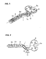
- FIG. 1 is a perspective view of a spacer block 1 that comprises a main body of the bone resection jig (hereafter, called “the jig") used during artificial knee joint replacement surgery in accordance with the present invention
- FIG. 2 is a top view
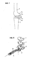
- FIG. 3 is a perspective view of the spacer block 1, a reference pin guide 2, and reference pins 3.
- front/back, up/down, and left/right directions are in reference to the knee in standing position and seen from the front and lateral sides.
- “Front” refers to the front of the knee (the patella side)
- upper refers to the femur side
- left side is a lateral side in the case of the left knee.
- the spacer block I is one that is inserted into a resection region of a resected distal end of a femur 4 and a resected proximal end of a tibia 5, and it supports the reference pin guide 2.
- the spacer block 1 is comprised of, from the front to the back, a grip 6, a hollow box 7 that has a perpendicular vertical hole 7a, and a reference spacer part 8.
- the grip 6 is a handle held by a surgeon, and it is provided with a plurality of vertical holes 6a in its middle portion for making alignment with the leg.
- the vertical hole 7a of the hollow box 7 is for inserting therein the reference pin guide 2, and it is square so that the reference pin guide 2 is not rotated inside.
- the reference pin guide 2 is supported when its base 2a is inserted into the vertical hole 7a of the hollow box 7.
- the reference pin guide 2 is a guide for bending the tip of the distal end ofthe femur 4 by 90° relative to the tip of the proximal end of the tibia 5 and further for inserting the reference pins 3 to the femur, and thus it is equipped with guide holes 9 for that purpose.
- the hollow box 7 is offset from the axis.
- the reason for this offsetting of the hollow box 7 is that it is set directly in front of the knee joint to increase the sighting performance of the aiming member, which will be described below, that is mounted on it, thus the vicinity of the hollow box 7 of the grip 6 is offset from the axis to hold it in a position that does not interfere with the line of si ght on or manipulations of the patellar tendon (and holds the patellar tendon off center on the outside).
- the reference pin guide 2 is, for this reason, off-center with respect to the axis side relative to the base 2a; and thus when the base 2a of the reference pin guide 2 is inserted into the vertical hole 7a of the hollow box 7, the reference pin guide 2 fully faces the reference spacer part 8.
- a cut-out 8a is made in the front tip (or, with respect to the knee, in the back) of the reference spacer part 8.
- the posterior cruciate ligament PCL
- the cut-out 8a is provided, and it is provided so as to not interfere with the PCL should it be preserved.
- the reference pins 3 are pins that are inserted into the guide holes 9 ofthe reference pin guide 2 and installed into the resection plane of the end part of the distal end 4a of the femur 4.
- a set screw 10 is provided in the hollow box 7 to clamp therein the base 2a of the reference pin guide 2, and the hollow box 7 and the set screw 10 are indeed provided in front of and shifted from the tibia 5.
- the knee joint is at approximately 180° when it is in the extension position ( FIG. 4 ).
- the extent of range A is determined by the surgeon in view of factors such as the severity of injury, age, body type, and the like.
- only a range B at the rip of the proximal end 5a of the tibia 5 is resected ( FIG. 6 ).
- the resection planes F H and T H of the femur 4 and the tibia 5, respectively are normally made flat and parallel, and thus an appropriate jig (not shown) may be used during the resection process for this reason.
- the size of resection range C between the tip of the distal end 4a of the femur 4 and the tip of the proximal end 5a of the tibia 5 is checked to make sure that it is the value determined prior to the surgery (whether an artificial knee joint of a predicted shape and size can be installed, or what shape and size of an artificial knee joint is appropriate).
- one or a plurality of additional spacers 11 are set one on top ofthe other on the reference spacer part 8 of the spacer block 1 ( FIG.
- the additional spacers are set layered because the thickness of the reference spacer 8 alone is insufficient for the reasons that will be described below.
- the additional spacers 11 are removed, and the femur 4 is placed in the flexion position ( FIG. 10 ).
- the additional spacers 11 are removed because the back of the distal end 4a of the femur 4 is thick and the femur 4 cannot be placed into the flexion position with these spacers in place.
- the reference spacer part 8 is made to be a thickness that can be inserted into the resection region C between the femur 4 side and the tibia 5 side with some margins, the femur 4 can be put into the flexion position when the spacers are removed.
- the reference pin guide 2 is inserted into the vertical hole 7a of the spacer block 1 from above, and its back surface 2b is brought into contact with the resection plane F H of the tip of the distal end of the femur 4 ( FIG. 11 ). This is done so as to bring the femur 4 into flexion of 90° relative to the tibia 5.
- the femur 4 can, nonetheless, be brought into an angle of greater than 90° flexion position to make deeper flexion possible; and so as to meet such a situation, the angle between the base 2a and back surface 2b of the reference pin guide 2 is set accordingly for such an angle.
- the reference pin guide 2 is pulled out upwards leaving the reference pins 3 in place, and the spacer block 1 is pulled out toward the front ( FIG. 12 ).
- the aiming member (sighting device) 12 is brought onto the reference pins 3 ( FIG. 13 ) by being guided thereby.
- the aiming member 12 is of an square shape when seen from the front ( FIG. 14 ), and it is provided with guide holes 13 into which the reference pins 3 can be inserted.
- the back surface 12b of the aiming member 12 is flat, and this back surface comes into contact with the resection plane F H of the tip of the distal end 4a of the femur 4.
- an indicator 14 that indicates the back resection plane F R , which is formed by next resection position made to the distal end 4a of the femur 4.
- the indicator 14 is a small through-hole or an oblong through-hole (slit) through which cutters, scribes, gauges, drills and the like can be inserted.
- slit through-hole
- cutters or the like are inserted into the slit 14, and marks are made on a line that will be a preset resection plane F R on the back of the distal end 4a of the femur 4.
- F R preset resection plane
- the resection plane F H of the tip of the distal end 4a of the femur 4 and the resection plane F R of the back of the distal end 4a of the femur 4 are substantially perpendicular with each other; however, they may be obtuse or acute angles depending on the shape and size of the artificial knee joint.
- the aiming member 12 is further provided with a slit 15 that serves as an indicator for cutting the front portion of the femur 4, which is the next resection position of the distal end 4a of the femur 4.
- the slit 15 is formed above the aforementioned through-hole or oblong through-hole in the aiming member 12, and a cutter or the like is inserted through the slit 15, and marks are made on a line that will become the resection plane F F of the front of the distal end 4a. Then, resection is performed at resection plane F F along the marks.
- This resection plane F F is often inclined so that the top part is slightly higher than the resection plane F H of the tip (in an obtuse angle). This is to improve the installation characteristics to the femur component of an artificial knee joint.
- the aiming member 12 is provided with a slit 16 which is a hole and the like and formed so as to be inclined upward and downward to chamfer the corners of the resection planes F H , F F , and F R .
- a slit 16 which is a hole and the like and formed so as to be inclined upward and downward to chamfer the corners of the resection planes F H , F F , and F R .
Landscapes
- Health & Medical Sciences (AREA)
- Life Sciences & Earth Sciences (AREA)
- Surgery (AREA)
- General Health & Medical Sciences (AREA)
- Public Health (AREA)
- Biomedical Technology (AREA)
- Heart & Thoracic Surgery (AREA)
- Orthopedic Medicine & Surgery (AREA)
- Engineering & Computer Science (AREA)
- Animal Behavior & Ethology (AREA)
- Veterinary Medicine (AREA)
- Molecular Biology (AREA)
- Nuclear Medicine, Radiotherapy & Molecular Imaging (AREA)
- Medical Informatics (AREA)
- Oral & Maxillofacial Surgery (AREA)
- Transplantation (AREA)
- Dentistry (AREA)
- Physical Education & Sports Medicine (AREA)
- Cardiology (AREA)
- Vascular Medicine (AREA)
- Surgical Instruments (AREA)
- Prostheses (AREA)
Abstract
Description
- The present invention relates to a bone resection jig used during artifcial knee joint replacement surgery.
- When a knee joint suffers knee osteoarthritis, rheumatoid arthritis, or bone tumors, or suffers external injury or the like, the part subject to joint damage at the tips of the femur and tibia is resected, and those parts are replaced with an artificial joint. This artificial knee joint, as conventionally seen, comprises a combination of a femur component, which has two condyles of medial and lateral, and a tibia component, which has a joint plate that bears these two condyles and allows them to rotate; and it is desirous that artificial knee joints that are comprised of such condyles and joint plates preferably be movable similarly to a biogenic knee joint.
- The femur and tibia are connected by numerous ligaments, and extension and flexion of them are made by tensioning and relaxing these ligaments. It is particularly desirable that when tensioning occurs tension be the same when in the extension position and when in the flexion position, and it is also desirable that flexion movement be smooth accompanying no pain. Also, since Japanese people often sit with their legs folded beneath them, it is necessary that deep flexion is possible. With these situations in mind, Patent Literature 1, listed below, proposes a bone resection jig that sets a bone resection range after confirming that tension is the same in the extension position and in the flexion position.
- However, the invention of this prior art checks (measures) the tension of ligaments in both extension and flexion positions; accordingly, the operation is troublesome, and it requires a longer surgical time. Further, the constitution is complex, and it includes many moving parts and adjustment parts, and further it requires numerous operation steps that are difficult and require proficiency. In addition, it is heavy and expensive.
- Patent Literature I: Patent Application Laid-Open (Kokai)
2007-75517 - The present invention proposes a bone resection jig based on the principle that the same tension can be derived in ligaments at the extension position and flexion position if the bone resection range (interval) is the same at both positions, and it provides a bone resection jig which is extremely simple in constitution and inexpensive. Furthermore, the present invention provides a bone resection jig that does not require proficiency to operate, can shorten surgery time, and reduces the impact on a patient.
- Given the problems above, the present invention is to provide a bone resection jig as claimed in Claim I which is for an artificial knee joint replacement surgery and is used when a back of a distal end of a femur in a flexion position is resected after a tip of the distal end of the femur and a tip of a proximal end of a tibia in an extension position are resected horizontally, and this bone resection jig includes: a spacer block comprised of a grip, a hollow box that is provided on an other end side of the grip and has a vertical hole therein, and a reference spacer part that extends out from the hollow box and is adapted be inserted into the resection region between femur and tibia; a reference pin guide which, when the femur and tibia are in the flexion position, is inserted into the vertical hole of the hollow box, extends on the reference spacer part to the other end side of the grip so as to come into contact with a resection plane of the tip of the distal end of the femur, and is formed with guide holes for guiding reference pins to be installed from a front side into the resection plane of the tip of the distal end of the femur; and an aiming member which, is, after the spacer block has been removed from a space between the femur and tibia leaving the reference pins, brought onto the reference pins by being guided thereby, the aiming member being provided with an indicator that indicates a resection plane at a back of the distal end of the femur when the aiming member comes into contact with the resection plane of the tip of the distal end of the femur.
- Further, in regards to the above-described bone resection jig, the present invention provides: a means as recited in
Claim 2 wherein the axis of the grip passes through the center of the reference spacer part while the area around the hollow box of the grip is offset relative to the axis to a position that can avoid interfere with the patellar tendon; a means as recited inClaim 3 wherein the resection plane of the tip of the distal end of the femur can be set at a right angle, obtuse angle or acute angle with respect to the resection plane of the back of the distal end of the femur; a means as recited inClaim 4 wherein two guide holes horizontally left and right are provided; a means as recited inClaim 5 wherein the indicators are through-holes that are formed in the aiming member at a variety of levels and angles; and a means as recited inClaim 6 wherein one or a plurality of additional spacers are put on another on the reference spacer part of the spacer block for measuring the distance of the resected distal end of the femur and the resected proximal end of the tibia in the extension position. - According to the bone resection jig of the present invention of Claim 1,the primary constituent parts are extremely few in number, which are a spacer block to be inserted into the resection region of the femur and tibia, a reference pin guide that appropriately sets the flexion position, and an aiming member that sets the resection range for the back of the distal end of the femur; and the constitution of the various constitutional elements of these parts is also simple. Accordingly, the bone resection jig of the present invention has a small number of constituent parts, is light in weight and inexpensive, and is simple in operation, thus not requiring a great deal of skill to operate.
- According to the means of
Claim 2, the hollow box does not block the field of view when the spacer block is inserted. According to the means ofClaim 3, the angle between the tip and back of the distal end of the femur can be matched to the shape of the femur side part of the artificial knee joint, and thus the femur side part can be inserted accurately and securely. According to the means ofClaim 4, the reference pin guide can be set accurately in the right attitude, which is horizontal. According to the means ofClaim 5, the back of the distal end of the femur can be set to resection planes of a variety of levels and angles. According to the means ofClaim 6, the femur can be placed in flexion of 90° with the reference spacer part of the spacer block left inserted after a prescribed amount of the distal end of the femur and the proximal end of the tibia are resected. -
-
FIG. 1 A perspective view of the spacer block. -
FIG. 2 A top view of the spacer block. -
FIG. 3 A perspective view showing a relationship between the spacer block, reference pin guide, and reference pins. -
FIG. 4 An explanatory diagram showing a manner of resection in the extension position. -
FIG. 5 An explanatory diagram showing a manner of resection in the extension position. -
FIG. 6 An explanatory diagram showing a manner of resection in the extension position. -
FIG. 7 An explanatory diagram showing a manner of resection in the extension position. -
FIG. 8 A perspective view showing a relationship between the spacer block and the additional spacers. -
FIG. 9 A side view showing the spacer block inserted into the bone resection region of the femur and tibia in the extension position. -
FIG. 10 A side view showing the spacer block inserted into the bone resection region of the femur and tibia in the flexion position. -
FIG. 11 A side view showing a manner of mounting the reference pin guide in the spacer block and of inserting the reference pins into the reference pin guide. -
FIG. 12 A side view showing the reference pin guide removed from the spacer block. -
FIG. 13 A side view showing a sighting device installed on the reference pins as guides. -
FIG. 14 A front view of the sighting device. -
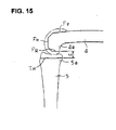
FIG. 15 A side view showing the back surface of the femur resected in the flexion position. - Modes for carrying out the present invention will be described below with reference to the drawings.
FIG. 1 is a perspective view of a spacer block 1 that comprises a main body of the bone resection jig (hereafter, called "the jig") used during artificial knee joint replacement surgery in accordance with the present invention,FIG. 2 is a top view, andFIG. 3 is a perspective view of the spacer block 1, areference pin guide 2, andreference pins 3. In the following, reference is made to front/back, up/down, and left/right directions. These are in reference to the knee in standing position and seen from the front and lateral sides. "Front" refers to the front of the knee (the patella side), and "upper" refers to the femur side; and for "left/right" the left side is a lateral side in the case of the left knee. - The spacer block I is one that is inserted into a resection region of a resected distal end of a
femur 4 and a resected proximal end of atibia 5, and it supports thereference pin guide 2. The spacer block 1 is comprised of, from the front to the back, agrip 6, ahollow box 7 that has a perpendicularvertical hole 7a, and areference spacer part 8. Thegrip 6 is a handle held by a surgeon, and it is provided with a plurality ofvertical holes 6a in its middle portion for making alignment with the leg. Thevertical hole 7a of thehollow box 7 is for inserting therein thereference pin guide 2, and it is square so that thereference pin guide 2 is not rotated inside. Thereference pin guide 2 is supported when itsbase 2a is inserted into thevertical hole 7a of thehollow box 7. Thereference pin guide 2 is a guide for bending the tip of the distal end ofthefemur 4 by 90° relative to the tip of the proximal end of thetibia 5 and further for inserting thereference pins 3 to the femur, and thus it is equipped with guide holes 9 for that purpose. - In the above structure, though the axis of the
grip 6 passes through the center of thereference spacer part 8, thehollow box 7 is offset from the axis. The reason for this offsetting of thehollow box 7 is that it is set directly in front of the knee joint to increase the sighting performance of the aiming member, which will be described below, that is mounted on it, thus the vicinity of thehollow box 7 of thegrip 6 is offset from the axis to hold it in a position that does not interfere with the line of si ght on or manipulations of the patellar tendon (and holds the patellar tendon off center on the outside). Thereference pin guide 2 is, for this reason, off-center with respect to the axis side relative to thebase 2a; and thus when thebase 2a of thereference pin guide 2 is inserted into thevertical hole 7a of thehollow box 7, thereference pin guide 2 fully faces thereference spacer part 8. - In addition, a cut-
out 8a is made in the front tip (or, with respect to the knee, in the back) of thereference spacer part 8. When knee joint is about to be replaced with an artificial knee joint, usually the posterior cruciate ligament (PCL) remains in its normal state; and in such cases, the PCL is preserved. For that reason, the cut-out 8a is provided, and it is provided so as to not interfere with the PCL should it be preserved. Meanwhile, thereference pins 3 are pins that are inserted into the guide holes 9 ofthereference pin guide 2 and installed into the resection plane of the end part of thedistal end 4a of thefemur 4. Aset screw 10 is provided in thehollow box 7 to clamp therein thebase 2a of thereference pin guide 2, and thehollow box 7 and theset screw 10 are indeed provided in front of and shifted from thetibia 5. - Next, surgery to replace a knee joint with an artificial knee joint using the various constituent parts described above will be described below with reference to
FIGs. 4 through 7 . The knee joint is at approximately 180° when it is in the extension position (FIG. 4 ). First, only a range A at the tip of thedistal end 4a of thefemur 4 is resected (FIG. 5 ). The extent of range A is determined by the surgeon in view of factors such as the severity of injury, age, body type, and the like. Then, only a range B at the rip of theproximal end 5a of thetibia 5 is resected (FIG. 6 ). While the extent of part B does depend on the severity of injury, it is also based on, considering the extent of range A, the shape and size of the artificial knee joint that is to be installed By means of the above, a range A + B = C is resected at the tip of thedistal end 4a of thefemur 4 and the tip of theproximal end 5a of the tibia 5 (FIG. 7 ). In this case, the resection planes FH and TH of thefemur 4 and thetibia 5, respectively, are normally made flat and parallel, and thus an appropriate jig (not shown) may be used during the resection process for this reason. - Then, in this state, the size of resection range C between the tip of the
distal end 4a of thefemur 4 and the tip of theproximal end 5a of thetibia 5 is checked to make sure that it is the value determined prior to the surgery (whether an artificial knee joint of a predicted shape and size can be installed, or what shape and size of an artificial knee joint is appropriate). To do this, in most cases, one or a plurality of additional spacers 11 are set one on top ofthe other on thereference spacer part 8 of the spacer block 1 (FIG. 8 ), and the resection range C between thefemur 4 side and thetibia 5 side is measured from that thickness of the spacers; and then it is determined whether a predicted artificial knee joint can be used (FIG. 9 ). Incidentally, the additional spacers are set layered because the thickness of thereference spacer 8 alone is insufficient for the reasons that will be described below. - Once these matters have been confirmed, the additional spacers 11 are removed, and the
femur 4 is placed in the flexion position (FIG. 10 ). The additional spacers 11 are removed because the back of thedistal end 4a of thefemur 4 is thick and thefemur 4 cannot be placed into the flexion position with these spacers in place. However, since thereference spacer part 8 is made to be a thickness that can be inserted into the resection region C between thefemur 4 side and thetibia 5 side with some margins, thefemur 4 can be put into the flexion position when the spacers are removed. Next, thereference pin guide 2 is inserted into thevertical hole 7a of the spacer block 1 from above, and its back surface 2b is brought into contact with the resection plane FH of the tip of the distal end of the femur 4 (FIG. 11 ). This is done so as to bring thefemur 4 into flexion of 90° relative to thetibia 5. Thefemur 4 can, nonetheless, be brought into an angle of greater than 90° flexion position to make deeper flexion possible; and so as to meet such a situation, the angle between thebase 2a and back surface 2b of thereference pin guide 2 is set accordingly for such an angle. - Once the above is set, the
reference pin guide 2 is pulled out upwards leaving the reference pins 3 in place, and the spacer block 1 is pulled out toward the front (FIG. 12 ). Then, the aiming member (sighting device) 12 is brought onto the reference pins 3 (FIG. 13 ) by being guided thereby. The aiming member 12 is of an square shape when seen from the front (FIG. 14 ), and it is provided with guide holes 13 into which the reference pins 3 can be inserted. The back surface 12b of the aiming member 12 is flat, and this back surface comes into contact with the resection plane FH of the tip of thedistal end 4a of thefemur 4. In the aiming member 12 is formed anindicator 14 that indicates the back resection plane FR, which is formed by next resection position made to thedistal end 4a of thefemur 4. - The
indicator 14 is a small through-hole or an oblong through-hole (slit) through which cutters, scribes, gauges, drills and the like can be inserted. Thus, cutters or the like are inserted into theslit 14, and marks are made on a line that will be a preset resection plane FR on the back of thedistal end 4a of thefemur 4. By way of cutting the back along the marks as references, the back will be cut on a resection plane FR. In this case, the resection plane FH of the tip of thedistal end 4a of thefemur 4 and the resection plane FR of the back of thedistal end 4a of thefemur 4 are substantially perpendicular with each other; however, they may be obtuse or acute angles depending on the shape and size of the artificial knee joint. - The aiming member 12 is further provided with a
slit 15 that serves as an indicator for cutting the front portion of thefemur 4, which is the next resection position of thedistal end 4a of thefemur 4. In other words, theslit 15 is formed above the aforementioned through-hole or oblong through-hole in the aiming member 12, and a cutter or the like is inserted through theslit 15, and marks are made on a line that will become the resection plane FF of the front of thedistal end 4a. Then, resection is performed at resection plane FF along the marks. This resection plane FF is often inclined so that the top part is slightly higher than the resection plane FH of the tip (in an obtuse angle). This is to improve the installation characteristics to the femur component of an artificial knee joint. - Furthermore, the aiming member 12 is provided with a
slit 16 which is a hole and the like and formed so as to be inclined upward and downward to chamfer the corners of the resection planes FH, FF, and FR. By way of cutting corners using theslit 16 as a guide, the bone is cut in a polygonal shape as shown inFIG. 15 . This chamfering is to improve the installation characteristics to the femur component of an artificial joint. When the femur component and tibia component of an artificial joint are installed, the surgery ends. A variety of shapes and sizes may be selected for the femur component and the tibia component as described above depending on the severity of the injury, age, body type, and the like. The foregoing describes an artificial joint replacement for a right knee; and for a left knee use, the spacer block I can be flipped over.Description of Reference Numerals 1 Spacer block 2 Reference pin guide 2a Base of the reference pin guide 2b Back surface of reference pin guide 3 Reference pins 4 Femur 4a Distal end of femur 5 Tibia 5a Proximal end of tibia 6 Grip 6a Hole in grip 7 Hollow box 7a Vertical hole of hollow box 8 Reference spacer part 8a Cut-out in reference spacer part 9 Guide holes 10 Connecting axis 11 Additional spacers 12 Aiming member 13 Insertion hole 14 Indicator (slit) 15 Indicator (slit) 16 Indicator (slit)
Claims (6)
- A bone resection jig for an artificial knee joint replacement surgery, being used when a back of a distal end of a femur in a flexion position is resected after a tip of the distal end of the femur and a tip of a proximal end of a tibia in an extension position are resected horizontally, wherein the bone resection jig comprises: a spacer block comprised of a grip, a hollow box that is provided on an other end side of the grip and has a vertical hole therein, and a reference spacer part that extends out from the hollow box and is adapted be inserted into the resection region between femur and tibia; a reference pin guide which, when the femur and tibia are in the flexion position, is inserted into the vertical hole of the hollow box, extends on the reference spacer part to the other end side of the grip so as to come into contact with a resection plane of the tip of the distal end of the femur, and is formed with guide holes for guiding reference pins to be installed from a front side into the resection plane of the tip of the distal end of the femur, and an aiming member which is, after the spacer block has been removed from a space between the femur and tibia leaving the reference pins, brought onto the reference pins by being guided thereby, the aiming member being provided with an indicator that indicates a resection plane at a back of the distal end of the femur when the aiming member comes into contact with the resection plane of the tip ofthe distal end of the femur.
- The bone resection jig used in artificial knee joint replacement surgery according to Claim 1, wherein an axis of the grip passes through a center of the reference spacer part, and an area around the hollow box of the grip is offset with respect to the axis to place patellar tendon in a position not in interference.
- The bone resection jig used in artificial knee joint replacement surgery according to Claim I or 2, wherein the resection plane of the tip of the distal end of the femur is set at a right angle, obtuse angle or acute angle with respect to a resection plane ofthe back of the distal end of the femur.
- The bone resection jig used in artificial knee joint replacement surgery of any according to Claims 1 through 3, wherein two guide holes are provided horizontally left and right.
- The bone resection jig used in artificial knee joint replacement surgery of many according to Claims 1 through 4, wherein the indicators are through-holes that are formed in the aiming member at a variety of levels and angles.
- The bone resection jig used in artificial knee joint replacement surgery of any according to Claims 1 through 5, wherein one or a plurality of additional spacers is layered on the reference spacer part for measuring a distance between a resected distal end of the femur and a resected proximal end of the tibia in the extension position.
Applications Claiming Priority (2)
| Application Number | Priority Date | Filing Date | Title |
|---|---|---|---|
| JP2010203873A JP5572491B2 (en) | 2010-09-13 | 2010-09-13 | Bone resection jig used for knee replacement surgery |
| PCT/JP2011/071537 WO2012036298A1 (en) | 2010-09-13 | 2011-09-13 | Bone resection jig used in surgical operation to replace artificial knee joint |
Publications (3)
| Publication Number | Publication Date |
|---|---|
| EP2617376A1 true EP2617376A1 (en) | 2013-07-24 |
| EP2617376A4 EP2617376A4 (en) | 2017-09-20 |
| EP2617376B1 EP2617376B1 (en) | 2019-07-03 |
Family
ID=45831750
Family Applications (1)
| Application Number | Title | Priority Date | Filing Date |
|---|---|---|---|
| EP11825296.4A Active EP2617376B1 (en) | 2010-09-13 | 2011-09-13 | Bone resection jig used in surgical operation to replace artificial knee joint |
Country Status (4)
| Country | Link |
|---|---|
| US (1) | US9220519B2 (en) |
| EP (1) | EP2617376B1 (en) |
| JP (1) | JP5572491B2 (en) |
| WO (1) | WO2012036298A1 (en) |
Cited By (1)
| Publication number | Priority date | Publication date | Assignee | Title |
|---|---|---|---|---|
| FR3011171A1 (en) * | 2013-10-01 | 2015-04-03 | Fournitures Hospitalieres Ind | ANCILLARY FOR THE TENSION OF INTERNAL AND EXTERNAL LATERAL LIGAMENTS OF A KNEE JOINT |
Families Citing this family (53)
| Publication number | Priority date | Publication date | Assignee | Title |
|---|---|---|---|---|
| JP5888861B2 (en) | 2011-02-24 | 2016-03-22 | 帝人ナカシマメディカル株式会社 | Surgical instruments used during knee replacement surgery |
| JP6505985B2 (en) * | 2014-05-30 | 2019-04-24 | アルスロデザイン株式会社 | Knee balancer |
| US20160015426A1 (en) | 2014-07-15 | 2016-01-21 | Treace Medical Concepts, Inc. | Bone positioning and cutting system and method |
| US9687250B2 (en) | 2015-01-07 | 2017-06-27 | Treace Medical Concepts, Inc. | Bone cutting guide systems and methods |
| US10849631B2 (en) | 2015-02-18 | 2020-12-01 | Treace Medical Concepts, Inc. | Pivotable bone cutting guide useful for bone realignment and compression techniques |
| US10653467B2 (en) | 2015-05-06 | 2020-05-19 | Treace Medical Concepts, Inc. | Intra-osseous plate system and method |
| US10849663B2 (en) | 2015-07-14 | 2020-12-01 | Treace Medical Concepts, Inc. | Bone cutting guide systems and methods |
| CA2991424C (en) | 2015-07-14 | 2025-11-18 | Treace Medical Concepts, Inc. | Bone positioning guide |
| US9622805B2 (en) | 2015-08-14 | 2017-04-18 | Treace Medical Concepts, Inc. | Bone positioning and preparing guide systems and methods |
| US10342590B2 (en) | 2015-08-14 | 2019-07-09 | Treace Medical Concepts, Inc. | Tarsal-metatarsal joint procedure utilizing fulcrum |
| EP4494582A3 (en) | 2015-08-14 | 2025-04-16 | Treace Medical Concepts, Inc. | Tarsal-metatarsal joint procedure utilizing fulcrum |
| WO2017049056A1 (en) | 2015-09-18 | 2017-03-23 | Treace Medical Concepts, Inc. | Joint spacer systems and methods |
| US10512470B1 (en) | 2016-08-26 | 2019-12-24 | Treace Medical Concepts, Inc. | Osteotomy procedure for correcting bone misalignment |
| US10582936B1 (en) | 2016-11-11 | 2020-03-10 | Treace Medical Concepts, Inc. | Devices and techniques for performing an osteotomy procedure on a first metatarsal to correct a bone misalignment |
| US10939939B1 (en) | 2017-02-26 | 2021-03-09 | Treace Medical Concepts, Inc. | Fulcrum for tarsal-metatarsal joint procedure |
| US11540928B2 (en) * | 2017-03-03 | 2023-01-03 | Engage Uni Llc | Unicompartmental knee arthroplasty |
| JP6975458B2 (en) | 2018-04-03 | 2021-12-01 | 株式会社ミヤタニ | Bone cutting tool |
| WO2020014457A1 (en) | 2018-07-11 | 2020-01-16 | Treace Medical Concepts, Inc. | Compressor-distractor for angularly realigning bone portions |
| WO2020014660A1 (en) | 2018-07-12 | 2020-01-16 | Treace Medical Concepts, Inc. | Multi-diameter bone pin for installing and aligning bone fixation plate while minimizing bone damage |
| CN108836426B (en) * | 2018-07-26 | 2024-09-06 | 佛山复星禅诚医院有限公司 | Osteotomy sighting device and application method thereof |
| USD906519S1 (en) * | 2018-10-23 | 2020-12-29 | DePuy Synthes Products, Inc. | Craniosynostosis bone manipulation device |
| US11607250B2 (en) | 2019-02-13 | 2023-03-21 | Treace Medical Concepts, Inc. | Tarsal-metatarsal joint procedure utilizing compressor-distractor and instrument providing sliding surface |
| AU2020325303B2 (en) | 2019-08-07 | 2026-02-19 | Treace Medical Concepts, Inc. | Bi-planar instrument for bone cutting and joint realignment procedure |
| US11889998B1 (en) | 2019-09-12 | 2024-02-06 | Treace Medical Concepts, Inc. | Surgical pin positioning lock |
| US11986251B2 (en) | 2019-09-13 | 2024-05-21 | Treace Medical Concepts, Inc. | Patient-specific osteotomy instrumentation |
| US11890039B1 (en) | 2019-09-13 | 2024-02-06 | Treace Medical Concepts, Inc. | Multi-diameter K-wire for orthopedic applications |
| US12490992B2 (en) | 2019-09-13 | 2025-12-09 | Treace Medical Concepts, Inc. | Patient-specific surgical methods and instrumentation |
| EP4027922A4 (en) | 2019-09-13 | 2023-10-04 | MIOS Marketing LLC, DBA RedPoint Medical 3D | ROBOTIC SURGICAL PROCESSES AND INSTRUMENTATION |
| WO2021155269A1 (en) | 2020-01-31 | 2021-08-05 | Treace Medical Concepts, Inc. | Metatarsophalangeal joint preparation and metatarsal realignment for fusion |
| EP4153071B1 (en) | 2020-05-19 | 2025-12-10 | Treace Medical Concepts, Inc. | Devices for treating metatarsus adductus |
| WO2022155569A1 (en) | 2021-01-18 | 2022-07-21 | Treace Medical Concepts, Inc. | Contoured bone plate with locking screw for bone compression, particularly across a tarsometatarsal joint |
| US12310603B2 (en) | 2021-02-18 | 2025-05-27 | Treace Medical Concepts, Inc. | System and technique for metatarsal realignment with reduced incision length |
| US12193683B2 (en) | 2021-05-20 | 2025-01-14 | Treace Medical Concepts, Inc. | Cut guide with integrated joint realignment features |
| USD1051382S1 (en) | 2022-02-23 | 2024-11-12 | Treace Medical Concepts, Inc. | Lesser metatarsal cut guide |
| USD1011524S1 (en) | 2022-02-23 | 2024-01-16 | Treace Medical Concepts, Inc. | Compressor-distractor for the foot |
| US12484917B2 (en) | 2022-02-23 | 2025-12-02 | Treace Medical Concepts, Inc. | First metatarsal lateral release instrument and technique |
| US12599389B2 (en) | 2022-02-23 | 2026-04-14 | Treace Medical Concepts, Inc. | Multi-sided cutting instrument for mobilizing small bones in the foot |
| USD1101146S1 (en) | 2022-02-23 | 2025-11-04 | Treace Medical Concepts, Inc. | Multi-sided cutting instrument for mobilizing small bones in the foot |
| USD1057155S1 (en) | 2022-02-23 | 2025-01-07 | Treace Medical Concepts, Inc. | Lesser metatarsal cut guide with parallel cut faces |
| USD1075012S1 (en) | 2022-02-23 | 2025-05-13 | Treace Medical Concepts, Inc. | Metatarsal lateral release instrument |
| USD1079011S1 (en) | 2022-02-23 | 2025-06-10 | Treace Medical Concepts, Inc. | Metatarsal cut guide with parallel cut faces |
| JP2025506811A (en) | 2022-02-23 | 2025-03-13 | トリース メディカル コンセプツ,インコーポレイティド | Anatomically adapted tarsometatarsal plate |
| US12478381B2 (en) | 2022-02-24 | 2025-11-25 | Treace Medical Concepts, Inc | Devices and techniques for treating lesser metatarsals of the foot |
| US12702484B2 (en) | 2022-03-31 | 2026-08-11 | Treace Medical Concepts, Inc. | Apparatus, system, and method for generating patient-specific implants and/or instrumentation |
| US12661133B2 (en) | 2022-05-12 | 2026-06-23 | Treace Medical Concepts, Inc. | Apparatus, system, and method for patient-specific methods and instrumentation |
| EP4539753A1 (en) | 2022-06-17 | 2025-04-23 | Treace Medical Concepts, Inc. | Apparatus, system, and method for generating patient-specific implants and/or instrumentation for osteotomies |
| USD1139998S1 (en) | 2022-07-21 | 2026-08-04 | Treace Medical Concepts, Inc. | Surgical cutting guide |
| USD1137663S1 (en) | 2022-10-17 | 2026-07-28 | Treace Medical Concepts, Inc. | Surgical cutting guide |
| JP2026505040A (en) | 2023-01-28 | 2026-02-10 | トリース メディカル コンセプツ,インコーポレイティド | Devices, systems, and methods for osteotomy |
| USD1068077S1 (en) | 2023-02-08 | 2025-03-25 | Treace Medical Concepts, Inc. | Orthopedic rasp for preparing an intercuneiform joint |
| USD1068078S1 (en) | 2023-02-08 | 2025-03-25 | Treace Medical Concepts, Inc. | Handle for an orthopedic instrument |
| WO2024168060A2 (en) | 2023-02-08 | 2024-08-15 | Treace Medical Concepts, Inc. | Orthopedic rasp and surgical technique for preparing an intercuneiform joint for fusion |
| KR102622418B1 (en) * | 2023-04-04 | 2024-01-08 | 주식회사 셀루메드 | Tibial Template and Handle for Minimally Invasive Total Knee Arthroplasty |
Family Cites Families (13)
| Publication number | Priority date | Publication date | Assignee | Title |
|---|---|---|---|---|
| US5520695A (en) * | 1992-02-14 | 1996-05-28 | Johnson & Johnson Professional, Inc. | Instruments for use in knee replacement surgery |
| US6258095B1 (en) * | 1998-03-28 | 2001-07-10 | Stryker Technologies Corporation | Methods and tools for femoral intermedullary revision surgery |
| FR2810227B1 (en) * | 2000-06-19 | 2002-09-06 | Buttet Michel De | FEMALE AND TIBIAL PREPARATION AND CUTTING DEVICE ADAPTED TO A SINGLE-COMPARTMENTAL KNEE PROSTHESIS AND FOR ITS PLACEMENT |
| US7708741B1 (en) * | 2001-08-28 | 2010-05-04 | Marctec, Llc | Method of preparing bones for knee replacement surgery |
| US6758850B2 (en) * | 2002-03-29 | 2004-07-06 | Depuy Orthopaedics, Inc. | Instruments and methods for flexion gap adjustment |
| GB2397526A (en) * | 2003-01-22 | 2004-07-28 | Biomet Merck Ltd | Bone jig with adjustment means |
| ATE327715T1 (en) * | 2003-04-25 | 2006-06-15 | Zimmer Gmbh | DEVICE FOR PREPARING A FEMURAL CONDYLE |
| US8025663B2 (en) * | 2003-12-30 | 2011-09-27 | Depuy Products, Inc. | Augments for surgical instruments |
| DE102004063977A1 (en) * | 2004-10-19 | 2006-06-22 | Mathys Ag Bettlach | Ligament Tension Device, Cutting Guide and Osteotomy Technique |
| JP4402029B2 (en) * | 2005-09-16 | 2010-01-20 | バイオメット・ジャパン株式会社 | Artificial knee joint installation jig |
| US7678115B2 (en) * | 2006-06-21 | 2010-03-16 | Howmedia Osteonics Corp. | Unicondylar knee implants and insertion methods therefor |
| US8721568B2 (en) * | 2009-03-31 | 2014-05-13 | Depuy (Ireland) | Method for performing an orthopaedic surgical procedure |
| EP2434991B1 (en) * | 2009-05-29 | 2018-01-24 | Smith&Nephew, Inc. | Apparatus for performing knee arthroplasty |
-
2010
- 2010-09-13 JP JP2010203873A patent/JP5572491B2/en active Active
-
2011
- 2011-09-13 EP EP11825296.4A patent/EP2617376B1/en active Active
- 2011-09-13 WO PCT/JP2011/071537 patent/WO2012036298A1/en not_active Ceased
- 2011-09-13 US US13/822,574 patent/US9220519B2/en active Active
Non-Patent Citations (1)
| Title |
|---|
| See references of WO2012036298A1 * |
Cited By (1)
| Publication number | Priority date | Publication date | Assignee | Title |
|---|---|---|---|---|
| FR3011171A1 (en) * | 2013-10-01 | 2015-04-03 | Fournitures Hospitalieres Ind | ANCILLARY FOR THE TENSION OF INTERNAL AND EXTERNAL LATERAL LIGAMENTS OF A KNEE JOINT |
Also Published As
| Publication number | Publication date |
|---|---|
| US9220519B2 (en) | 2015-12-29 |
| WO2012036298A1 (en) | 2012-03-22 |
| EP2617376B1 (en) | 2019-07-03 |
| US20130184714A1 (en) | 2013-07-18 |
| JP2012055597A (en) | 2012-03-22 |
| EP2617376A4 (en) | 2017-09-20 |
| JP5572491B2 (en) | 2014-08-13 |
Similar Documents
| Publication | Publication Date | Title |
|---|---|---|
| US9220519B2 (en) | Bone resection jig used in artificial knee joint replacement surgery | |
| CN107252338B (en) | Method and apparatus for performing knee arthroplasty | |
| EP2135565B1 (en) | Amz tibial tuberosity transfer system |
Legal Events
| Date | Code | Title | Description |
|---|---|---|---|
| PUAI | Public reference made under article 153(3) epc to a published international application that has entered the european phase |
Free format text: ORIGINAL CODE: 0009012 |
|
| 17P | Request for examination filed |
Effective date: 20130312 |
|
| AK | Designated contracting states |
Kind code of ref document: A1 Designated state(s): AL AT BE BG CH CY CZ DE DK EE ES FI FR GB GR HR HU IE IS IT LI LT LU LV MC MK MT NL NO PL PT RO RS SE SI SK SM TR |
|
| DAX | Request for extension of the european patent (deleted) | ||
| RA4 | Supplementary search report drawn up and despatched (corrected) |
Effective date: 20170821 |
|
| RIC1 | Information provided on ipc code assigned before grant |
Ipc: A61B 17/02 20060101ALI20170814BHEP Ipc: A61F 2/38 20060101ALI20170814BHEP Ipc: A61B 17/56 20060101AFI20170814BHEP Ipc: A61B 17/15 20060101ALI20170814BHEP Ipc: A61F 2/46 20060101ALI20170814BHEP Ipc: A61B 17/17 20060101ALI20170814BHEP |
|
| STAA | Information on the status of an ep patent application or granted ep patent |
Free format text: STATUS: EXAMINATION IS IN PROGRESS |
|
| 17Q | First examination report despatched |
Effective date: 20180514 |
|
| GRAP | Despatch of communication of intention to grant a patent |
Free format text: ORIGINAL CODE: EPIDOSNIGR1 |
|
| STAA | Information on the status of an ep patent application or granted ep patent |
Free format text: STATUS: GRANT OF PATENT IS INTENDED |
|
| INTG | Intention to grant announced |
Effective date: 20190204 |
|
| GRAS | Grant fee paid |
Free format text: ORIGINAL CODE: EPIDOSNIGR3 |
|
| GRAA | (expected) grant |
Free format text: ORIGINAL CODE: 0009210 |
|
| STAA | Information on the status of an ep patent application or granted ep patent |
Free format text: STATUS: THE PATENT HAS BEEN GRANTED |
|
| AK | Designated contracting states |
Kind code of ref document: B1 Designated state(s): AL AT BE BG CH CY CZ DE DK EE ES FI FR GB GR HR HU IE IS IT LI LT LU LV MC MK MT NL NO PL PT RO RS SE SI SK SM TR |
|
| REG | Reference to a national code |
Ref country code: GB Ref legal event code: FG4D |
|
| REG | Reference to a national code |
Ref country code: CH Ref legal event code: EP Ref country code: AT Ref legal event code: REF Ref document number: 1150032 Country of ref document: AT Kind code of ref document: T Effective date: 20190715 |
|
| REG | Reference to a national code |
Ref country code: IE Ref legal event code: FG4D |
|
| REG | Reference to a national code |
Ref country code: DE Ref legal event code: R096 Ref document number: 602011060251 Country of ref document: DE |
|
| REG | Reference to a national code |
Ref country code: NL Ref legal event code: MP Effective date: 20190703 |
|
| REG | Reference to a national code |
Ref country code: LT Ref legal event code: MG4D |
|
| REG | Reference to a national code |
Ref country code: AT Ref legal event code: MK05 Ref document number: 1150032 Country of ref document: AT Kind code of ref document: T Effective date: 20190703 |
|
| PG25 | Lapsed in a contracting state [announced via postgrant information from national office to epo] |
Ref country code: CZ Free format text: LAPSE BECAUSE OF FAILURE TO SUBMIT A TRANSLATION OF THE DESCRIPTION OR TO PAY THE FEE WITHIN THE PRESCRIBED TIME-LIMIT Effective date: 20190703 Ref country code: FI Free format text: LAPSE BECAUSE OF FAILURE TO SUBMIT A TRANSLATION OF THE DESCRIPTION OR TO PAY THE FEE WITHIN THE PRESCRIBED TIME-LIMIT Effective date: 20190703 Ref country code: SE Free format text: LAPSE BECAUSE OF FAILURE TO SUBMIT A TRANSLATION OF THE DESCRIPTION OR TO PAY THE FEE WITHIN THE PRESCRIBED TIME-LIMIT Effective date: 20190703 Ref country code: HR Free format text: LAPSE BECAUSE OF FAILURE TO SUBMIT A TRANSLATION OF THE DESCRIPTION OR TO PAY THE FEE WITHIN THE PRESCRIBED TIME-LIMIT Effective date: 20190703 Ref country code: AT Free format text: LAPSE BECAUSE OF FAILURE TO SUBMIT A TRANSLATION OF THE DESCRIPTION OR TO PAY THE FEE WITHIN THE PRESCRIBED TIME-LIMIT Effective date: 20190703 Ref country code: PT Free format text: LAPSE BECAUSE OF FAILURE TO SUBMIT A TRANSLATION OF THE DESCRIPTION OR TO PAY THE FEE WITHIN THE PRESCRIBED TIME-LIMIT Effective date: 20191104 Ref country code: NL Free format text: LAPSE BECAUSE OF FAILURE TO SUBMIT A TRANSLATION OF THE DESCRIPTION OR TO PAY THE FEE WITHIN THE PRESCRIBED TIME-LIMIT Effective date: 20190703 Ref country code: NO Free format text: LAPSE BECAUSE OF FAILURE TO SUBMIT A TRANSLATION OF THE DESCRIPTION OR TO PAY THE FEE WITHIN THE PRESCRIBED TIME-LIMIT Effective date: 20191003 Ref country code: LT Free format text: LAPSE BECAUSE OF FAILURE TO SUBMIT A TRANSLATION OF THE DESCRIPTION OR TO PAY THE FEE WITHIN THE PRESCRIBED TIME-LIMIT Effective date: 20190703 Ref country code: BG Free format text: LAPSE BECAUSE OF FAILURE TO SUBMIT A TRANSLATION OF THE DESCRIPTION OR TO PAY THE FEE WITHIN THE PRESCRIBED TIME-LIMIT Effective date: 20191003 |
|
| PG25 | Lapsed in a contracting state [announced via postgrant information from national office to epo] |
Ref country code: ES Free format text: LAPSE BECAUSE OF FAILURE TO SUBMIT A TRANSLATION OF THE DESCRIPTION OR TO PAY THE FEE WITHIN THE PRESCRIBED TIME-LIMIT Effective date: 20190703 Ref country code: RS Free format text: LAPSE BECAUSE OF FAILURE TO SUBMIT A TRANSLATION OF THE DESCRIPTION OR TO PAY THE FEE WITHIN THE PRESCRIBED TIME-LIMIT Effective date: 20190703 Ref country code: LV Free format text: LAPSE BECAUSE OF FAILURE TO SUBMIT A TRANSLATION OF THE DESCRIPTION OR TO PAY THE FEE WITHIN THE PRESCRIBED TIME-LIMIT Effective date: 20190703 Ref country code: AL Free format text: LAPSE BECAUSE OF FAILURE TO SUBMIT A TRANSLATION OF THE DESCRIPTION OR TO PAY THE FEE WITHIN THE PRESCRIBED TIME-LIMIT Effective date: 20190703 Ref country code: GR Free format text: LAPSE BECAUSE OF FAILURE TO SUBMIT A TRANSLATION OF THE DESCRIPTION OR TO PAY THE FEE WITHIN THE PRESCRIBED TIME-LIMIT Effective date: 20191004 Ref country code: IS Free format text: LAPSE BECAUSE OF FAILURE TO SUBMIT A TRANSLATION OF THE DESCRIPTION OR TO PAY THE FEE WITHIN THE PRESCRIBED TIME-LIMIT Effective date: 20191103 |
|
| PG25 | Lapsed in a contracting state [announced via postgrant information from national office to epo] |
Ref country code: TR Free format text: LAPSE BECAUSE OF FAILURE TO SUBMIT A TRANSLATION OF THE DESCRIPTION OR TO PAY THE FEE WITHIN THE PRESCRIBED TIME-LIMIT Effective date: 20190703 |
|
| PG25 | Lapsed in a contracting state [announced via postgrant information from national office to epo] |
Ref country code: IT Free format text: LAPSE BECAUSE OF FAILURE TO SUBMIT A TRANSLATION OF THE DESCRIPTION OR TO PAY THE FEE WITHIN THE PRESCRIBED TIME-LIMIT Effective date: 20190703 Ref country code: RO Free format text: LAPSE BECAUSE OF FAILURE TO SUBMIT A TRANSLATION OF THE DESCRIPTION OR TO PAY THE FEE WITHIN THE PRESCRIBED TIME-LIMIT Effective date: 20190703 Ref country code: PL Free format text: LAPSE BECAUSE OF FAILURE TO SUBMIT A TRANSLATION OF THE DESCRIPTION OR TO PAY THE FEE WITHIN THE PRESCRIBED TIME-LIMIT Effective date: 20190703 Ref country code: EE Free format text: LAPSE BECAUSE OF FAILURE TO SUBMIT A TRANSLATION OF THE DESCRIPTION OR TO PAY THE FEE WITHIN THE PRESCRIBED TIME-LIMIT Effective date: 20190703 Ref country code: DK Free format text: LAPSE BECAUSE OF FAILURE TO SUBMIT A TRANSLATION OF THE DESCRIPTION OR TO PAY THE FEE WITHIN THE PRESCRIBED TIME-LIMIT Effective date: 20190703 |
|
| PG25 | Lapsed in a contracting state [announced via postgrant information from national office to epo] |
Ref country code: SK Free format text: LAPSE BECAUSE OF FAILURE TO SUBMIT A TRANSLATION OF THE DESCRIPTION OR TO PAY THE FEE WITHIN THE PRESCRIBED TIME-LIMIT Effective date: 20190703 Ref country code: IS Free format text: LAPSE BECAUSE OF FAILURE TO SUBMIT A TRANSLATION OF THE DESCRIPTION OR TO PAY THE FEE WITHIN THE PRESCRIBED TIME-LIMIT Effective date: 20200224 Ref country code: SM Free format text: LAPSE BECAUSE OF FAILURE TO SUBMIT A TRANSLATION OF THE DESCRIPTION OR TO PAY THE FEE WITHIN THE PRESCRIBED TIME-LIMIT Effective date: 20190703 Ref country code: MC Free format text: LAPSE BECAUSE OF FAILURE TO SUBMIT A TRANSLATION OF THE DESCRIPTION OR TO PAY THE FEE WITHIN THE PRESCRIBED TIME-LIMIT Effective date: 20190703 |
|
| REG | Reference to a national code |
Ref country code: CH Ref legal event code: PL |
|
| REG | Reference to a national code |
Ref country code: DE Ref legal event code: R097 Ref document number: 602011060251 Country of ref document: DE |
|
| PLBE | No opposition filed within time limit |
Free format text: ORIGINAL CODE: 0009261 |
|
| STAA | Information on the status of an ep patent application or granted ep patent |
Free format text: STATUS: NO OPPOSITION FILED WITHIN TIME LIMIT |
|
| PG2D | Information on lapse in contracting state deleted |
Ref country code: IS |
|
| PG25 | Lapsed in a contracting state [announced via postgrant information from national office to epo] |
Ref country code: LU Free format text: LAPSE BECAUSE OF NON-PAYMENT OF DUE FEES Effective date: 20190913 Ref country code: CH Free format text: LAPSE BECAUSE OF NON-PAYMENT OF DUE FEES Effective date: 20190930 Ref country code: LI Free format text: LAPSE BECAUSE OF NON-PAYMENT OF DUE FEES Effective date: 20190930 |
|
| REG | Reference to a national code |
Ref country code: BE Ref legal event code: MM Effective date: 20190930 |
|
| 26N | No opposition filed |
Effective date: 20200603 |
|
| PG25 | Lapsed in a contracting state [announced via postgrant information from national office to epo] |
Ref country code: BE Free format text: LAPSE BECAUSE OF NON-PAYMENT OF DUE FEES Effective date: 20190930 Ref country code: SI Free format text: LAPSE BECAUSE OF FAILURE TO SUBMIT A TRANSLATION OF THE DESCRIPTION OR TO PAY THE FEE WITHIN THE PRESCRIBED TIME-LIMIT Effective date: 20190703 |
|
| PG25 | Lapsed in a contracting state [announced via postgrant information from national office to epo] |
Ref country code: FR Free format text: LAPSE BECAUSE OF NON-PAYMENT OF DUE FEES Effective date: 20190930 |
|
| PG25 | Lapsed in a contracting state [announced via postgrant information from national office to epo] |
Ref country code: CY Free format text: LAPSE BECAUSE OF FAILURE TO SUBMIT A TRANSLATION OF THE DESCRIPTION OR TO PAY THE FEE WITHIN THE PRESCRIBED TIME-LIMIT Effective date: 20190703 |
|
| PG25 | Lapsed in a contracting state [announced via postgrant information from national office to epo] |
Ref country code: HU Free format text: LAPSE BECAUSE OF FAILURE TO SUBMIT A TRANSLATION OF THE DESCRIPTION OR TO PAY THE FEE WITHIN THE PRESCRIBED TIME-LIMIT; INVALID AB INITIO Effective date: 20110913 Ref country code: MT Free format text: LAPSE BECAUSE OF FAILURE TO SUBMIT A TRANSLATION OF THE DESCRIPTION OR TO PAY THE FEE WITHIN THE PRESCRIBED TIME-LIMIT Effective date: 20190703 |
|
| PG25 | Lapsed in a contracting state [announced via postgrant information from national office to epo] |
Ref country code: MK Free format text: LAPSE BECAUSE OF FAILURE TO SUBMIT A TRANSLATION OF THE DESCRIPTION OR TO PAY THE FEE WITHIN THE PRESCRIBED TIME-LIMIT Effective date: 20190703 |
|
| PGFP | Annual fee paid to national office [announced via postgrant information from national office to epo] |
Ref country code: DE Payment date: 20250731 Year of fee payment: 15 |
|
| PGFP | Annual fee paid to national office [announced via postgrant information from national office to epo] |
Ref country code: GB Payment date: 20250731 Year of fee payment: 15 |
|
| PGFP | Annual fee paid to national office [announced via postgrant information from national office to epo] |
Ref country code: IE Payment date: 20250801 Year of fee payment: 15 |
|
| REG | Reference to a national code |
Ref country code: DE Ref legal event code: R081 Ref document number: 602011060251 Country of ref document: DE Owner name: KANEYAMA, RYUTAKU, KISARAZU-SHI, JP Free format text: FORMER OWNERS: KANEYAMA, RYUTAKU, KISARAZU-SHI, CHIBA, JP; NAKASHIMA MEDICAL CO., LTD., OKAYAMA-SHI, JP Ref country code: DE Ref legal event code: R081 Ref document number: 602011060251 Country of ref document: DE Owner name: NAKASHIMA HEALTHFORCE CO., LTD., JP Free format text: FORMER OWNERS: KANEYAMA, RYUTAKU, KISARAZU-SHI, CHIBA, JP; NAKASHIMA MEDICAL CO., LTD., OKAYAMA-SHI, JP |