EP2617317A2 - Tubular cosmetic container with rotary open and shut-type brush - Google Patents
Tubular cosmetic container with rotary open and shut-type brush Download PDFInfo
- Publication number
- EP2617317A2 EP2617317A2 EP11825491.1A EP11825491A EP2617317A2 EP 2617317 A2 EP2617317 A2 EP 2617317A2 EP 11825491 A EP11825491 A EP 11825491A EP 2617317 A2 EP2617317 A2 EP 2617317A2
- Authority
- EP
- European Patent Office
- Prior art keywords
- combined
- rotation
- protuberance
- cap
- brush
- Prior art date
- Legal status (The legal status is an assumption and is not a legal conclusion. Google has not performed a legal analysis and makes no representation as to the accuracy of the status listed.)
- Granted
Links
Images




Classifications
-
- A—HUMAN NECESSITIES
- A45—HAND OR TRAVELLING ARTICLES
- A45D—HAIRDRESSING OR SHAVING EQUIPMENT; EQUIPMENT FOR COSMETICS OR COSMETIC TREATMENTS, e.g. FOR MANICURING OR PEDICURING
- A45D40/00—Casings or accessories specially adapted for storing or handling solid or pasty toiletry or cosmetic substances, e.g. shaving soaps or lipsticks
- A45D40/26—Appliances specially adapted for applying pasty paint, e.g. using roller, using a ball
- A45D40/262—Appliances specially adapted for applying pasty paint, e.g. using roller, using a ball using a brush or the like
-
- A—HUMAN NECESSITIES
- A45—HAND OR TRAVELLING ARTICLES
- A45D—HAIRDRESSING OR SHAVING EQUIPMENT; EQUIPMENT FOR COSMETICS OR COSMETIC TREATMENTS, e.g. FOR MANICURING OR PEDICURING
- A45D34/00—Containers or accessories specially adapted for handling liquid toiletry or cosmetic substances, e.g. perfumes
- A45D34/04—Appliances specially adapted for applying liquid, e.g. using roller or ball
- A45D34/042—Appliances specially adapted for applying liquid, e.g. using roller or ball using a brush or the like
-
- A—HUMAN NECESSITIES
- A46—BRUSHWARE
- A46B—BRUSHES
- A46B11/00—Brushes with reservoir or other means for applying substances, e.g. paints, pastes, water
-
- A—HUMAN NECESSITIES
- A46—BRUSHWARE
- A46B—BRUSHES
- A46B11/00—Brushes with reservoir or other means for applying substances, e.g. paints, pastes, water
- A46B11/001—Brushes with reservoir or other means for applying substances, e.g. paints, pastes, water with integral reservoirs
- A46B11/002—Brushes with reservoir or other means for applying substances, e.g. paints, pastes, water with integral reservoirs pressurised at moment of use manually or by powered means
-
- A—HUMAN NECESSITIES
- A46—BRUSHWARE
- A46B—BRUSHES
- A46B11/00—Brushes with reservoir or other means for applying substances, e.g. paints, pastes, water
- A46B11/0072—Details
- A46B11/0079—Arrangements for preventing undesired leakage or dispensing
-
- A—HUMAN NECESSITIES
- A46—BRUSHWARE
- A46B—BRUSHES
- A46B11/00—Brushes with reservoir or other means for applying substances, e.g. paints, pastes, water
- A46B11/0072—Details
- A46B11/0079—Arrangements for preventing undesired leakage or dispensing
- A46B11/0086—Means for closing or sealing, e.g. toothpaste outlet when brush not in use thereby preventing leakage or drying out
-
- A—HUMAN NECESSITIES
- A46—BRUSHWARE
- A46B—BRUSHES
- A46B11/00—Brushes with reservoir or other means for applying substances, e.g. paints, pastes, water
- A46B11/0072—Details
- A46B11/0079—Arrangements for preventing undesired leakage or dispensing
- A46B11/0089—Caps or covers for bristles
-
- A—HUMAN NECESSITIES
- A45—HAND OR TRAVELLING ARTICLES
- A45D—HAIRDRESSING OR SHAVING EQUIPMENT; EQUIPMENT FOR COSMETICS OR COSMETIC TREATMENTS, e.g. FOR MANICURING OR PEDICURING
- A45D2200/00—Details not otherwise provided for in A45D
- A45D2200/05—Details of containers
- A45D2200/051—Airtight containers
-
- A—HUMAN NECESSITIES
- A46—BRUSHWARE
- A46B—BRUSHES
- A46B11/00—Brushes with reservoir or other means for applying substances, e.g. paints, pastes, water
- A46B11/001—Brushes with reservoir or other means for applying substances, e.g. paints, pastes, water with integral reservoirs
- A46B11/002—Brushes with reservoir or other means for applying substances, e.g. paints, pastes, water with integral reservoirs pressurised at moment of use manually or by powered means
- A46B11/0041—Flexible or deformable reservoirs, e.g. resilient bulbs, compressible tubes
- A46B11/0048—Flexible or deformable reservoirs, e.g. resilient bulbs, compressible tubes where a tube is twisted along length
-
- A—HUMAN NECESSITIES
- A46—BRUSHWARE
- A46B—BRUSHES
- A46B2200/00—Brushes characterized by their functions, uses or applications
- A46B2200/10—For human or animal care
- A46B2200/1046—Brush used for applying cosmetics
Definitions
- the invention relates to a rotation on/off-type brush-tube-shaped cosmetic container 100.
- It is a tube-type cosmetic container 110 formed through the tube container 110 which is pressured to discharge the cosmetic out of a discharge hole 111.
- It comprises: a fixation body 120 inserted into the front end of the tube container 110, the central portion of the fixation body 120 formed with a protruding portion for closing 122, the lower part of the protruding portion for closing 122 forming a discharge hole 121, and the two sides of the outer periphery of the upper part of the protruding portion respectively forming a screw-type spiral groove 130 from the upper end to the central part; a sealing cap 140 formed with a discharge hole 141, the central part of the discharge hole 141 communicated to discharge the cosmetic, the protruding portion for closing 122 inserted into the discharge hole 141 when descending from the lower part so that the discharge hole 141 is closed, and the outer peripheral surface of the seal cap formed with a combined protuberance 142 which is
- a cosmetic container generally accommodates toner, lotion and eye cream.
- a gel type cosmetic such as lotion, cream and so on
- a tube-type cosmetic container which is easy to be used and has low preparation cost.
- a brush in order that the gel type cosmetic may be more easily coated, a brush, most made of porous elastic materials such as sponge and so on, is attached to a discharge outlet.
- the invention relates to a rotation on/off-type brush-tube-type cosmetic container. If a tube container is accidentally pressured, it still may prevent cosmetic from being leaked during use or while in storage.
- the objective of the invention is as follows: based on the shape of a spiral groove which can effectively act, a seal cap and a rotation cap can be firmly fixed at the maximum rising / descending position, and a rising / descending action can be implemented in the smooth manner.
- the invention relates to a rotation on/off-type brush-tube-type cosmetic container.
- a tube-type cosmetic container 110 formed through the tube container 110 which is pressured to discharge the cosmetic out of a discharge hole 111, wherein it comprises: a fixation body 120 inserted into the front end of the tube container 110, the central portion of the fixation body 120 formed with a protruding portion for closing 122, the lower portion of the protruding portion for closing 122 forming a discharge hole 121, and the two sides of the outer periphery of the upper part of the protruding portion respectively forming a screw-type spiral groove 130 from the upper end to the central part; a sealing cap 140 formed with a discharge hole 141, the central part of the discharge hole 141 communicated to discharge the cosmetics; the protruding portion for closing 122 is inserted into the discharge hole 141 when descending from the lower part, so that the discharge hole 141 is closed, the outer peripheral surface of the seal cap formed with a combined protuberance
- the spiral groove 130 comprises: an inserting groove 131 used for being inserted into the combined protuberances 142 to be combined; an upper horizontal groove 132 facilitating the combined protuberance 142 to be combined at the maximum rising position, and forming a space of which the perimeter is equal to or less than that of the combined protuberance 142, so that the combined protuberance 142 is embedded into the space; a lower horizontal groove 133 facilitating the combined protuberance 142 to be combined at the maximum descending position, and forming a space of which the perimeter is equal to or less than that of the combined protuberance 142, so that the combined protuberance 142 is embedded into the space; an inclination groove 134 forming a space having a gap with the combined protuberance 142, to guarantee not to interfere the movement when the combined protuberance 142 rises / descends; a bending portion 135 at the position where the combined protuberance 142 starts to descend and a round-shaped curved surface formed from the upper horizontal groove
- the invention is characterized in that: the lower part of the brush nozzle (160) is also formed with a space portion 161 interconnected with a plurality of the nozzles 162.
- the invention has the following advantages: although only through the action of turning a rotation cap, the cosmetic container may still be simply opened / closed to discharge the cosmetics; under the case that a tube container is accidentally pressured during use or while in storage , it still can prevent the cosmetic from being leaked;
- the invention has the following advantages: based on the shape of a spiral groove, a seal cap and the rotation cap can be firmly fixed at the maximum rising / descending position, and the rising / descending action can be implemented in a smooth manner.
- a rotation on/off-type brush-tube-shaped cosmetic container of the invention comprises a container 110, a fixation body 120, a seal cap 140, a rotation cap 150 and a brush nozzle 160.
- the inner part of a tube container 100 is reserved and stored with the cosmetic.
- the tube container 110 can be made of a plurality of materials; preferably, it is generally made of synthetic resin.
- the upper end of the tube container 110 is formed with a discharge hole 111. When the user presses the tube container 110, the cosmetic is discharged out from the discharge hole 111.
- the fixation body 120 will be described in the followings: As shown in Figure 1 , the fixation body 120 is sandwiched into the front end of the tube container 110 and forms a protruding portion for closing122 at the central part of the fixation body 120. As shown in figure 1 , the lower part of the protruding portion for closing 122 is formed with a discharge hole 121, so that the cosmetic is discharged out of the discharge hole 111. As shown in Figures 1 and 3 , the two sides of the outer periphery of the upper part of the fixation body 120 respectively form a screw-type spiral groove 130 from the upper end to the central part and are combined with a combined protuberance 142 which will be described below.
- the spiral groove 130 comprises: an inserting groove 131 used for being inserted into the combined protuberances 142 to be combined; an upper horizontal groove 132 facilitating the combined protuberance 142 to be combined at the maximum rising position, and forming a space of which the perimeter is equal to or less than that of the combined protuberance 142, so that the combined protuberance 142 is embedded into the space; a lower horizontal groove 133 facilitating the combined protuberance 142 to be combined at the maximum descending position, and forming a space of which the perimeter is equal to or less than that of the combined protuberance 142, so that the combined protuberance 142 is embedded into the space; an inclination groove 134 forming a space having a gap with the combined protuberance 142, to guarantee not to interfere the movement when the combined protuberance 142 rises / descends; a bending portion 135 at the
- the seal cap 140 may facilitate the central part to be communicated and discharges the cosmetic outwards when the seal cap 140 is opened.
- the seal cap 140 is formed with a discharge hole 141.
- the protruding portion for closing 122 is inserted from the lower part, thus facilitating the discharge hole 141 to be closed.
- the outer peripheral surface of the seal cap 140 is formed with a combined protuberance 142. The combined protuberance 142 is inserted into the spiral groove 130 to be combined with the spiral groove 130.
- a rotation cap 150 is crossly formed with an access groove 151 at the upper end thereof, which provides an access for the seal cap 140.
- the inner part of the rotation cap 150 is formed with a vertical guide groove 152 combined with the combined protuberance 142.
- the upper part of the rotation cap 150 is formed with a mounting portion 153 of a brush nozzle.
- the rotation cap 150 is rotatablely combined with the outer peripheral surface of the fixation body 120. With the rotation movement, the combined protuberance 142 combined with the vertical guide groove 152 is linked to be moved. With the movement of the spiral groove 130, the seal cap 140 may be risen and descended at the same time.
- a brush nozzle 160 is described. As shown in Figures 1 and 3 , a brush nozzle 160 is inserted into the mounting portion 153 of the brush nozzle, fixed, and formed with more than one the nozzle inserted into a brush 163. On the other hand, as shown in Figure 1 , preferably, the lower part of the brush nozzle 160 also forms a space portion 162 interconnected with a plurality of the nozzles 161, so that the cosmetic is discharged more smoothly and effectively.
- the rotation on/off-type brush-tube-shaped cosmetic container 100 also comprises an over cap 170 attached to the fixation body 120 during assembly and disassembly.
Landscapes
- Closures For Containers (AREA)
- Brushes (AREA)
Abstract
Description
- The invention relates to a rotation on/off-type brush-tube-shaped
cosmetic container 100. It is a tube-typecosmetic container 110 formed through thetube container 110 which is pressured to discharge the cosmetic out of adischarge hole 111. It comprises: afixation body 120 inserted into the front end of thetube container 110, the central portion of thefixation body 120 formed with a protruding portion forclosing 122, the lower part of the protruding portion forclosing 122 forming adischarge hole 121, and the two sides of the outer periphery of the upper part of the protruding portion respectively forming a screw-typespiral groove 130 from the upper end to the central part; asealing cap 140 formed with adischarge hole 141, the central part of thedischarge hole 141 communicated to discharge the cosmetic, the protruding portion forclosing 122 inserted into thedischarge hole 141 when descending from the lower part so that thedischarge hole 141 is closed, and the outer peripheral surface of the seal cap formed with a combinedprotuberance 142 which is combined with thespiral groove 130 in a manner of being inserted into thespiral groove 130; arotation cap 150 crossly formed with anaccess groove 151 at the upper end thereof, which provides an access for theseal cap 140, the inner part of therotation cap 150 formed with avertical guide groove 152 combined with the combinedprotuberance 142, the upper part of therotation cap 150 forming amounting portion 153, and therotation cap 150 rotatablely combined with the outer peripheral surface of thefixation body 120 and facilitating theseal cap 140 to be lift / descended with the rotation movement; abrush nozzle 160 inserted into themounting portion 153 of the brush nozzle, fixed, and formed with more than one the nozzle inserted into abrush 163; - A cosmetic container generally accommodates toner, lotion and eye cream. In particular, a gel type cosmetic, such as lotion, cream and so on, widely uses a tube-type cosmetic container which is easy to be used and has low preparation cost. As to the existing cosmetic container, in order that the gel type cosmetic may be more easily coated, a brush, most made of porous elastic materials such as sponge and so on, is attached to a discharge outlet.
- However, as to such existing tube-type cosmetic container attached by the brush, under the case that there is not a proper opening, the tube container may be accidentally pressured and it may occur cosmetic leakage phenomenon, during use or while in storage.
- Through the above solved problems in the prior art, in the invention, only a rotation cap is simply rotated and then the opening / closing action can be simply implemented to discharge the cosmetic. The invention relates to a rotation on/off-type brush-tube-type cosmetic container. If a tube container is accidentally pressured, it still may prevent cosmetic from being leaked during use or while in storage.
- Moreover, the objective of the invention is as follows: based on the shape of a spiral groove which can effectively act, a seal cap and a rotation cap can be firmly fixed at the maximum rising / descending position, and a rising / descending action can be implemented in the smooth manner.
- To solve the above problems, the invention relates to a rotation on/off-type brush-tube-type cosmetic container. It is a tube-type
cosmetic container 110 formed through thetube container 110 which is pressured to discharge the cosmetic out of adischarge hole 111, wherein it comprises: afixation body 120 inserted into the front end of thetube container 110, the central portion of thefixation body 120 formed with a protruding portion for closing 122, the lower portion of the protruding portion for closing 122 forming adischarge hole 121, and the two sides of the outer periphery of the upper part of the protruding portion respectively forming a screw-typespiral groove 130 from the upper end to the central part; asealing cap 140 formed with adischarge hole 141, the central part of thedischarge hole 141 communicated to discharge the cosmetics; the protruding portion forclosing 122 is inserted into thedischarge hole 141 when descending from the lower part, so that thedischarge hole 141 is closed, the outer peripheral surface of the seal cap formed with a combinedprotuberance 142 which is combined with thespiral groove 130 in a manner of being inserted into thespiral groove 130; arotation cap 150 crossly formed with anaccess groove 151 at the upper end thereof, which provides an access for theseal cap 140, the inner part of therotation cap 150 formed with avertical guide groove 152 combined with the combinedprotuberance 142, the upper part of therotation cap 150 forming amounting portion 153, and therotation cap 150 rotatablely combined with the outer peripheral surface of thefixation body 120 and facilitating theseal cap 140 to be risen / descended with the rotation movement; abrush nozzle 160 inserted into themounting portion 153 of the brush nozzle, fixed, and formed with more than one the nozzle inserted into abrush 163, and an overcap 170 being capable of being attached to thefixation body 120 during assembly and disassembly. - Furthermore, the invention is characterized in that the
spiral groove 130 comprises: aninserting groove 131 used for being inserted into the combinedprotuberances 142 to be combined; an upperhorizontal groove 132 facilitating the combinedprotuberance 142 to be combined at the maximum rising position, and forming a space of which the perimeter is equal to or less than that of the combinedprotuberance 142, so that the combinedprotuberance 142 is embedded into the space; a lowerhorizontal groove 133 facilitating the combinedprotuberance 142 to be combined at the maximum descending position, and forming a space of which the perimeter is equal to or less than that of the combinedprotuberance 142, so that the combinedprotuberance 142 is embedded into the space; aninclination groove 134 forming a space having a gap with the combinedprotuberance 142, to guarantee not to interfere the movement when the combinedprotuberance 142 rises / descends; abending portion 135 at the position where the combinedprotuberance 142 starts to descend and a round-shaped curved surface formed from the upperhorizontal groove 132 toward theinclination groove 134. - In another aspect, the invention is characterized in that: the lower part of the brush nozzle (160) is also formed with a
space portion 161 interconnected with a plurality of thenozzles 162. - The invention has the following advantages: although only through the action of turning a rotation cap, the cosmetic container may still be simply opened / closed to discharge the cosmetics; under the case that a tube container is accidentally pressured during use or while in storage , it still can prevent the cosmetic from being leaked;
- Moreover, the invention has the following advantages: based on the shape of a spiral groove, a seal cap and the rotation cap can be firmly fixed at the maximum rising / descending position, and the rising / descending action can be implemented in a smooth manner.
-
-
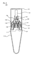
Figure 1 is a sectional view of a front surface of a rotation on/off-type brush-tube-type cosmetic container according to the invention. -
Figure 2 is a sectional view of a side surface of a rotation on/off-type brush-tube-type cosmetic container according to the invention. -
Figure 3 is an exploded space diagram of a rotation on/off-type brush-tube-type cosmetic container according to the invention. -
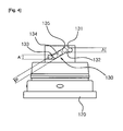
Figure 4 is a detailed diagram of a spiral groove of a rotation on/off-type brush-tube-type cosmetic container according to the invention. -
Figure 5 is a sectional view of a main part when a rotation on/off-type brush-tube-type cosmetic container is closed according to the invention. -
Figure 6 is a sectional view of a main part when a rotation on/off-type brush-tube-type cosmetic container is opened according to the invention. - Thereinafter, referring to the drawings, a rotation on/off-type brush-tube-shaped cosmetic container will be described in details. Firstly, it shall be noted that, in the drawings, the same structural parts or elements shall be indicated by the same number as far as possible. As to the description of the invention, in order to prevent the spirit of the invention from becoming unclear, the detailed specification of the related known functions or structures will be omitted.
- As shown in
Figures 1 and3 , a rotation on/off-type brush-tube-shaped cosmetic container of the invention comprises acontainer 110, afixation body 120, aseal cap 140, arotation cap 150 and abrush nozzle 160. - As shown in
Figure 1 , the inner part of atube container 100 is reserved and stored with the cosmetic. Although thetube container 110 can be made of a plurality of materials; preferably, it is generally made of synthetic resin. As shown inFigure 1 , the upper end of thetube container 110 is formed with adischarge hole 111. When the user presses thetube container 110, the cosmetic is discharged out from thedischarge hole 111. - The
fixation body 120 will be described in the followings: As shown inFigure 1 , thefixation body 120 is sandwiched into the front end of thetube container 110 and forms a protruding portion for closing122 at the central part of thefixation body 120. As shown infigure 1 , the lower part of the protruding portion forclosing 122 is formed with adischarge hole 121, so that the cosmetic is discharged out of thedischarge hole 111. As shown inFigures 1 and3 , the two sides of the outer periphery of the upper part of thefixation body 120 respectively form a screw-type spiral groove 130 from the upper end to the central part and are combined with a combinedprotuberance 142 which will be described below. - On the other hand, as shown in
Figure 4 , in the case that the rotation on/off-type brush-tube-typecosmetic container 100 is prepared; preferably, thespiral groove 130 comprises: aninserting groove 131 used for being inserted into the combinedprotuberances 142 to be combined; an upperhorizontal groove 132 facilitating the combinedprotuberance 142 to be combined at the maximum rising position, and forming a space of which the perimeter is equal to or less than that of the combinedprotuberance 142, so that the combinedprotuberance 142 is embedded into the space; a lowerhorizontal groove 133 facilitating the combinedprotuberance 142 to be combined at the maximum descending position, and forming a space of which the perimeter is equal to or less than that of the combinedprotuberance 142, so that the combinedprotuberance 142 is embedded into the space; aninclination groove 134 forming a space having a gap with the combinedprotuberance 142, to guarantee not to interfere the movement when the combinedprotuberance 142 rises / descends; abending portion 135 at the position where the combinedprotuberance 142 starts to descend and a round-shaped curved surface formed from the upperhorizontal groove 132 toward theinclination groove 134. - Subsequently, the
seal cap 140 is described. As shownFigures 1 and6 , theseal cap 140 may facilitate the central part to be communicated and discharges the cosmetic outwards when theseal cap 140 is opened. As shown inFigure 5 , theseal cap 140 is formed with adischarge hole 141. When theseal cap 140 descends, the protruding portion forclosing 122 is inserted from the lower part, thus facilitating thedischarge hole 141 to be closed. Moreover, as shown inFigures 1 and3 , the outer peripheral surface of theseal cap 140 is formed with a combinedprotuberance 142. The combinedprotuberance 142 is inserted into thespiral groove 130 to be combined with thespiral groove 130. - Subsequently, the
seal cap 150 is described. As shown inFigures 1 and3 , arotation cap 150 is crossly formed with anaccess groove 151 at the upper end thereof, which provides an access for theseal cap 140. The inner part of therotation cap 150 is formed with avertical guide groove 152 combined with the combinedprotuberance 142. The upper part of therotation cap 150 is formed with amounting portion 153 of a brush nozzle. As shown inFigures 1 and3 , therotation cap 150 is rotatablely combined with the outer peripheral surface of thefixation body 120. With the rotation movement, the combinedprotuberance 142 combined with thevertical guide groove 152 is linked to be moved. With the movement of thespiral groove 130, theseal cap 140 may be risen and descended at the same time. - Subsequently, a
brush nozzle 160 is described. As shown inFigures 1 and3 , abrush nozzle 160 is inserted into themounting portion 153 of the brush nozzle, fixed, and formed with more than one the nozzle inserted into abrush 163. On the other hand, as shown inFigure 1 , preferably, the lower part of thebrush nozzle 160 also forms aspace portion 162 interconnected with a plurality of thenozzles 161, so that the cosmetic is discharged more smoothly and effectively. - On the other hand, as shown in
Figures 1 and3 , the rotation on/off-type brush-tube-shapedcosmetic container 100 also comprises an overcap 170 attached to thefixation body 120 during assembly and disassembly. - Hereinbefore, some preferable embodiments are disclosed in the drawings and the description. Here, although specified terms are used, they are only used for describing the objective of the invention but not for limiting the definition or the scope of the invention written in the claims. Accordingly, those skilled in the art shall understand that various modifications and other equivalent examples can be implemented according to the above examples. Therefore, the technical scope, required to be protected in the invention, shall depend on the technical thoughts of claims attached.
Claims (3)
- A rotation on/off-type brush-tube-shaped cosmetic container (100), wherein a tube container (110) is pressured so that the cosmetic is discharged from a discharge hole (111), and the rotation on/off-type brush-tube-shaped cosmetic container (100) is characterized by comprising:a fixation body (120) inserted into the front end of the tube container (110), the central part of the fixation body (120) formed with a protruding portion for closing (122), the lower part of the protruding portion for closing (122) forming a discharge hole (121), and the two sides of the outer periphery of the upper part of the protruding portion respectively forming a screw-type spiral groove (130) from the upper end to the central part;a seal cap (140) formed with a discharge hole (141), the central part of the discharge hole (141) communicated to discharge the cosmetic, the protruding portion for closing (122) inserted into the discharge hole (141) when the seal cap (140) descends from the lower part, so that the discharge hole (141) is closed, and the outer peripheral surface of the seal cap formed with a combined protuberance (142) which is combined with the spiral groove (130) in a manner of being inserted into the spiral groove (130);a rotation cap (150) crossly formed with an access groove (151) at the upper end thereof, which provides an access for the seal cap (140), the inner part of the rotation cap (150) formed with a vertical guide groove (152) combined with the combined protuberance (142), the upper part of the rotation cap (150) formed with a mounting portion (153) of a brush nozzle, and the rotation cap (150) rotatablely combined with the outer peripheral surface of the fixation body (120) and facilitating the seal cap to be risen / descended with the rotation movement;a brush nozzle (160) inserted into the mounting portion (153) of the brush nozzle to be fixed, and formed with more than one the nozzle inserted into a brush (163), andan over cap (170) being capable of being attached to the fixation body (120) during assembly and disassembly.
- The rotation on/off-type brush-tube-shaped cosmetic container (100) according to claim 1, wherein
the spiral groove (130) comprises:an inserting groove (131) used for being inserted into the combined protuberance (142) to be combined;an upper horizontal groove (132) facilitating the combined protuberance (142) to be combined at the maximum rising position, and forming a space of which the perimeter is equal to or less than that of the combined protuberance (142), so that the combined protuberance (142) is embedded into the space;a lower horizontal groove (133) facilitating the combined protuberance (142) to be combined at the maximum descending position, and forming a space of which the perimeter is equal to or less than that of the combined protuberance (142), so that the combined protuberance (142) is embedded into the space;an inclination groove (134) forming a space having a gap with the combined protuberance (142), to guarantee not to interfere the movement when the combined protuberance (142) rises / descends;a bending portion (135) at the position where the combined protuberance (142) starts to descend, and a round-shaped curved surface formed from the upper horizontal groove (132) toward the inclination groove (134). - The rotation on/off-type brush-tube-shaped cosmetic container (100) according to claim 1 or 2, wherein the lower part of the brush nozzle (160) is also formed with a space portion (162) interconnected with a plurality of the nozzles (161).
Applications Claiming Priority (2)
| Application Number | Priority Date | Filing Date | Title |
|---|---|---|---|
| KR20100091726A KR101192211B1 (en) | 2010-09-17 | 2010-09-17 | Turning type Cosmetics Tube with Brush |
| PCT/KR2011/006903 WO2012036531A2 (en) | 2010-09-17 | 2011-09-19 | Tubular cosmetic container with rotary open and shut-type brush |
Publications (3)
| Publication Number | Publication Date |
|---|---|
| EP2617317A2 true EP2617317A2 (en) | 2013-07-24 |
| EP2617317A4 EP2617317A4 (en) | 2014-03-05 |
| EP2617317B1 EP2617317B1 (en) | 2015-06-24 |
Family
ID=45832144
Family Applications (1)
| Application Number | Title | Priority Date | Filing Date |
|---|---|---|---|
| EP11825491.1A Not-in-force EP2617317B1 (en) | 2010-09-17 | 2011-09-19 | Tubular cosmetic container with rotary open and shut-type brush |
Country Status (7)
| Country | Link |
|---|---|
| US (1) | US8939670B2 (en) |
| EP (1) | EP2617317B1 (en) |
| JP (1) | JP5874883B2 (en) |
| KR (1) | KR101192211B1 (en) |
| CN (1) | CN103079427B (en) |
| ES (1) | ES2547573T3 (en) |
| WO (1) | WO2012036531A2 (en) |
Families Citing this family (25)
| Publication number | Priority date | Publication date | Assignee | Title |
|---|---|---|---|---|
| USD743273S1 (en) * | 2010-02-25 | 2015-11-17 | Digital Innovations Llc | Liquid dispenser |
| KR101192211B1 (en) | 2010-09-17 | 2012-10-17 | (주)연우 | Turning type Cosmetics Tube with Brush |
| KR101363349B1 (en) * | 2012-08-30 | 2014-02-17 | (주)연우 | Tube type cosmetic vessel having a dual exhaust means |
| KR101452982B1 (en) * | 2013-05-21 | 2014-10-22 | (주)연우 | Turning Ejection Bottle |
| KR101559078B1 (en) * | 2013-10-10 | 2015-10-08 | (주)연우 | Turning Ejection Bottle |
| KR101530580B1 (en) * | 2013-10-24 | 2015-06-23 | (주)연우 | Turning type Tube vessel |
| KR101537543B1 (en) * | 2014-03-13 | 2015-07-20 | (주)연우 | Rotatable opening and shutting type Tube vessel |
| KR101619957B1 (en) * | 2015-04-10 | 2016-05-12 | (주)연우 | Cosmetic vessel having mixed two-type materials |
| CN106308320B (en) * | 2015-06-24 | 2017-09-05 | 姜红成 | A kind of cup for vibration of taking advantage of a situation |
| KR101717972B1 (en) * | 2016-04-26 | 2017-03-20 | (주)연우 | Container for Discharging Powder |
| KR101748746B1 (en) * | 2016-11-02 | 2017-06-19 | 변영광 | Case for liquid state cosmetics |
| KR101896036B1 (en) * | 2016-11-17 | 2018-09-06 | (주)연우 | Turning type cosmetic vessel |
| CN108245774A (en) * | 2016-12-29 | 2018-07-06 | 株式会社基纳希施 | It is equipped with the cosmetics containers of micropin idler wheel |
| US10953428B2 (en) * | 2017-01-06 | 2021-03-23 | Wagner Spray Tech Corporation | Fluid applicator device with fluid control mechanism |
| JP6906364B2 (en) * | 2017-05-16 | 2021-07-21 | ロレアル | A device for applying cosmetics to human keratin substances |
| JP1602468S (en) | 2017-05-29 | 2018-04-23 | ||
| JP1602467S (en) * | 2017-05-29 | 2018-04-23 | ||
| USD907502S1 (en) | 2017-11-15 | 2021-01-12 | Pollen Gear Llc | Tube with closure |
| USD899254S1 (en) | 2017-11-15 | 2020-10-20 | Pollen Gear Llc | Access-resistant tube |
| USD886635S1 (en) * | 2017-11-15 | 2020-06-09 | Pollen Gear Llc | Container |
| USD853248S1 (en) * | 2018-05-23 | 2019-07-09 | Joyce T. Betts | Container |
| WO2021111854A1 (en) * | 2019-12-03 | 2021-06-10 | 花王株式会社 | Container |
| KR102194355B1 (en) * | 2020-05-18 | 2020-12-24 | 주식회사 엔게인 | Ampoule chamber |
| KR102719691B1 (en) | 2021-11-04 | 2024-10-23 | (주)연우 | Container |
| WO2025160512A1 (en) * | 2024-01-26 | 2025-07-31 | Vanderbilt University | Hair comb attachment for fnirs probes to improve snr and subject inclusivity |
Family Cites Families (18)
| Publication number | Priority date | Publication date | Assignee | Title |
|---|---|---|---|---|
| JP4218151B2 (en) | 1999-09-30 | 2009-02-04 | ぺんてる株式会社 | Applicator with valve |
| FR2814723B1 (en) * | 2000-10-03 | 2003-04-11 | Oreal | DISPENSING HEAD AND CONTAINER PROVIDED WITH SUCH A HEAD |
| US7261226B2 (en) * | 2001-12-12 | 2007-08-28 | Portola Packaging, Inc. | Closure having rotatable spout and axially movable stem |
| US6702161B2 (en) * | 2001-12-12 | 2004-03-09 | Portola Packaging, Inc. | Closure having rotatable spout and axially movable stem |
| ITMI20022143A1 (en) * | 2002-10-09 | 2004-04-10 | Fulvio Reggiani | CONTAINER APPLICATOR OF FLUID PRODUCTS, PARTICULARLY FOR COSMETIC AND PHARMACEUTICAL USE. |
| JP4216058B2 (en) | 2002-12-04 | 2009-01-28 | 大成化工株式会社 | Cap with application member for container contents |
| FR2870696B1 (en) * | 2004-05-27 | 2006-09-01 | Oreal | DEVICE FOR PACKAGING AND APPLYING A PRODUCT |
| KR200381133Y1 (en) | 2005-01-26 | 2005-04-08 | 박선주 | nozzle opening and shutting apparatus of cosmetic bottle for drying prevention |
| US7287927B2 (en) * | 2005-03-21 | 2007-10-30 | Chuen Chern Co., Ltd. | Valve assembly |
| KR200425584Y1 (en) | 2006-06-26 | 2006-09-06 | 김규진 | Rotating nozzle switch for cosmetic container |
| KR100789290B1 (en) * | 2006-09-28 | 2007-12-28 | 변영광 | Tubular Liquid Cosmetic Container |
| JP3135360U (en) * | 2007-07-02 | 2007-09-13 | 勤辰有限公司 | Container contents discharge structure |
| KR100917348B1 (en) | 2007-09-14 | 2009-09-15 | (주)영진팩 | Outlet of cosmetic container |
| KR100867684B1 (en) * | 2008-02-05 | 2008-11-10 | 주식회사 한국피앤피 | Puff integral liquid cosmetic container with rotation closure |
| KR100949320B1 (en) * | 2008-03-26 | 2010-03-30 | 화성화학 주식회사 | Liquid cosmetic containers |
| KR200449855Y1 (en) | 2008-04-28 | 2010-08-16 | (주)연우 | Tubular cosmetic container |
| US8534948B2 (en) * | 2009-03-06 | 2013-09-17 | Hct Asia Ltd | Dispenser with a cam path |
| KR101192211B1 (en) | 2010-09-17 | 2012-10-17 | (주)연우 | Turning type Cosmetics Tube with Brush |
-
2010
- 2010-09-17 KR KR20100091726A patent/KR101192211B1/en not_active Expired - Fee Related
-
2011
- 2011-09-19 CN CN201180042722.8A patent/CN103079427B/en not_active Expired - Fee Related
- 2011-09-19 EP EP11825491.1A patent/EP2617317B1/en not_active Not-in-force
- 2011-09-19 ES ES11825491.1T patent/ES2547573T3/en active Active
- 2011-09-19 WO PCT/KR2011/006903 patent/WO2012036531A2/en not_active Ceased
- 2011-09-19 US US13/817,434 patent/US8939670B2/en active Active
- 2011-09-19 JP JP2013529079A patent/JP5874883B2/en active Active
Also Published As
| Publication number | Publication date |
|---|---|
| CN103079427B (en) | 2015-10-14 |
| KR20120029728A (en) | 2012-03-27 |
| US8939670B2 (en) | 2015-01-27 |
| JP2013541969A (en) | 2013-11-21 |
| JP5874883B2 (en) | 2016-03-02 |
| EP2617317A4 (en) | 2014-03-05 |
| ES2547573T3 (en) | 2015-10-07 |
| US20130189018A1 (en) | 2013-07-25 |
| WO2012036531A2 (en) | 2012-03-22 |
| WO2012036531A3 (en) | 2012-06-28 |
| CN103079427A (en) | 2013-05-01 |
| EP2617317B1 (en) | 2015-06-24 |
| KR101192211B1 (en) | 2012-10-17 |
Similar Documents
| Publication | Publication Date | Title |
|---|---|---|
| US20130189018A1 (en) | Rotation on/off-type brush-tube-shaped cosmetic container | |
| KR100963155B1 (en) | Dual cosmetic container with airless pump | |
| JP2017512719A (en) | Rotating open / close tube container | |
| CN106102511A (en) | Frost class cosmetics containers | |
| KR20160033418A (en) | Pump type Compact case | |
| KR101535087B1 (en) | Pump type compact case | |
| KR102423782B1 (en) | Stick type cosmetic storage | |
| CN113148418A (en) | Liquid outlet container | |
| KR101530580B1 (en) | Turning type Tube vessel | |
| CN218008613U (en) | Cosmetic container | |
| KR101192716B1 (en) | Rotate pressing out type cosmetic container | |
| CN115177088A (en) | Cosmetic container | |
| KR101180737B1 (en) | Turning type tube vessel with a brush | |
| CN110155490A (en) | A kind of L-type ball valve All-in-One switching pressing imbibition bottle with sucker | |
| KR20110081476A (en) | Cosmetic container with one-touch cap | |
| KR101143948B1 (en) | Compact case | |
| KR20150044869A (en) | Tube vessel for cosmetic | |
| ES2944068T3 (en) | Cosmetic case comprising a deformable side wall | |
| JP3153523U (en) | Liquid container | |
| JP7487343B2 (en) | Contents container | |
| JP2008296947A (en) | Extrusion container | |
| KR102080707B1 (en) | Cosmetic dispenser | |
| KR102415057B1 (en) | Shut tighting device of button for pump container | |
| KR101366406B1 (en) | lipgloss | |
| US20050147459A1 (en) | Product dispensing device and container equipped therewith |
Legal Events
| Date | Code | Title | Description |
|---|---|---|---|
| PUAI | Public reference made under article 153(3) epc to a published international application that has entered the european phase |
Free format text: ORIGINAL CODE: 0009012 |
|
| 17P | Request for examination filed |
Effective date: 20130312 |
|
| AK | Designated contracting states |
Kind code of ref document: A2 Designated state(s): AL AT BE BG CH CY CZ DE DK EE ES FI FR GB GR HR HU IE IS IT LI LT LU LV MC MK MT NL NO PL PT RO RS SE SI SK SM TR |
|
| DAX | Request for extension of the european patent (deleted) | ||
| A4 | Supplementary search report drawn up and despatched |
Effective date: 20140205 |
|
| RIC1 | Information provided on ipc code assigned before grant |
Ipc: A46B 11/00 20060101ALI20140130BHEP Ipc: A45D 40/08 20060101AFI20140130BHEP Ipc: A45D 40/26 20060101ALI20140130BHEP |
|
| GRAP | Despatch of communication of intention to grant a patent |
Free format text: ORIGINAL CODE: EPIDOSNIGR1 |
|
| INTG | Intention to grant announced |
Effective date: 20150112 |
|
| INTG | Intention to grant announced |
Effective date: 20150114 |
|
| GRAS | Grant fee paid |
Free format text: ORIGINAL CODE: EPIDOSNIGR3 |
|
| GRAA | (expected) grant |
Free format text: ORIGINAL CODE: 0009210 |
|
| AK | Designated contracting states |
Kind code of ref document: B1 Designated state(s): AL AT BE BG CH CY CZ DE DK EE ES FI FR GB GR HR HU IE IS IT LI LT LU LV MC MK MT NL NO PL PT RO RS SE SI SK SM TR |
|
| REG | Reference to a national code |
Ref country code: GB Ref legal event code: FG4D |
|
| REG | Reference to a national code |
Ref country code: CH Ref legal event code: EP |
|
| REG | Reference to a national code |
Ref country code: AT Ref legal event code: REF Ref document number: 732538 Country of ref document: AT Kind code of ref document: T Effective date: 20150715 |
|
| REG | Reference to a national code |
Ref country code: IE Ref legal event code: FG4D |
|
| REG | Reference to a national code |
Ref country code: DE Ref legal event code: R096 Ref document number: 602011017398 Country of ref document: DE |
|
| REG | Reference to a national code |
Ref country code: FR Ref legal event code: PLFP Year of fee payment: 5 |
|
| REG | Reference to a national code |
Ref country code: ES Ref legal event code: FG2A Ref document number: 2547573 Country of ref document: ES Kind code of ref document: T3 Effective date: 20151007 |
|
| PG25 | Lapsed in a contracting state [announced via postgrant information from national office to epo] |
Ref country code: HR Free format text: LAPSE BECAUSE OF FAILURE TO SUBMIT A TRANSLATION OF THE DESCRIPTION OR TO PAY THE FEE WITHIN THE PRESCRIBED TIME-LIMIT Effective date: 20150624 Ref country code: NO Free format text: LAPSE BECAUSE OF FAILURE TO SUBMIT A TRANSLATION OF THE DESCRIPTION OR TO PAY THE FEE WITHIN THE PRESCRIBED TIME-LIMIT Effective date: 20150924 Ref country code: LT Free format text: LAPSE BECAUSE OF FAILURE TO SUBMIT A TRANSLATION OF THE DESCRIPTION OR TO PAY THE FEE WITHIN THE PRESCRIBED TIME-LIMIT Effective date: 20150624 Ref country code: FI Free format text: LAPSE BECAUSE OF FAILURE TO SUBMIT A TRANSLATION OF THE DESCRIPTION OR TO PAY THE FEE WITHIN THE PRESCRIBED TIME-LIMIT Effective date: 20150624 |
|
| REG | Reference to a national code |
Ref country code: AT Ref legal event code: MK05 Ref document number: 732538 Country of ref document: AT Kind code of ref document: T Effective date: 20150624 |
|
| REG | Reference to a national code |
Ref country code: LT Ref legal event code: MG4D |
|
| PG25 | Lapsed in a contracting state [announced via postgrant information from national office to epo] |
Ref country code: RS Free format text: LAPSE BECAUSE OF FAILURE TO SUBMIT A TRANSLATION OF THE DESCRIPTION OR TO PAY THE FEE WITHIN THE PRESCRIBED TIME-LIMIT Effective date: 20150624 Ref country code: BG Free format text: LAPSE BECAUSE OF FAILURE TO SUBMIT A TRANSLATION OF THE DESCRIPTION OR TO PAY THE FEE WITHIN THE PRESCRIBED TIME-LIMIT Effective date: 20150924 Ref country code: GR Free format text: LAPSE BECAUSE OF FAILURE TO SUBMIT A TRANSLATION OF THE DESCRIPTION OR TO PAY THE FEE WITHIN THE PRESCRIBED TIME-LIMIT Effective date: 20150925 Ref country code: LV Free format text: LAPSE BECAUSE OF FAILURE TO SUBMIT A TRANSLATION OF THE DESCRIPTION OR TO PAY THE FEE WITHIN THE PRESCRIBED TIME-LIMIT Effective date: 20150624 |
|
| REG | Reference to a national code |
Ref country code: NL Ref legal event code: MP Effective date: 20150624 |
|
| PG25 | Lapsed in a contracting state [announced via postgrant information from national office to epo] |
Ref country code: EE Free format text: LAPSE BECAUSE OF FAILURE TO SUBMIT A TRANSLATION OF THE DESCRIPTION OR TO PAY THE FEE WITHIN THE PRESCRIBED TIME-LIMIT Effective date: 20150624 |
|
| PG25 | Lapsed in a contracting state [announced via postgrant information from national office to epo] |
Ref country code: IS Free format text: LAPSE BECAUSE OF FAILURE TO SUBMIT A TRANSLATION OF THE DESCRIPTION OR TO PAY THE FEE WITHIN THE PRESCRIBED TIME-LIMIT Effective date: 20151024 Ref country code: AT Free format text: LAPSE BECAUSE OF FAILURE TO SUBMIT A TRANSLATION OF THE DESCRIPTION OR TO PAY THE FEE WITHIN THE PRESCRIBED TIME-LIMIT Effective date: 20150624 Ref country code: RO Free format text: LAPSE BECAUSE OF NON-PAYMENT OF DUE FEES Effective date: 20150624 Ref country code: SK Free format text: LAPSE BECAUSE OF FAILURE TO SUBMIT A TRANSLATION OF THE DESCRIPTION OR TO PAY THE FEE WITHIN THE PRESCRIBED TIME-LIMIT Effective date: 20150624 Ref country code: PT Free format text: LAPSE BECAUSE OF FAILURE TO SUBMIT A TRANSLATION OF THE DESCRIPTION OR TO PAY THE FEE WITHIN THE PRESCRIBED TIME-LIMIT Effective date: 20151026 Ref country code: CZ Free format text: LAPSE BECAUSE OF FAILURE TO SUBMIT A TRANSLATION OF THE DESCRIPTION OR TO PAY THE FEE WITHIN THE PRESCRIBED TIME-LIMIT Effective date: 20150624 Ref country code: PL Free format text: LAPSE BECAUSE OF FAILURE TO SUBMIT A TRANSLATION OF THE DESCRIPTION OR TO PAY THE FEE WITHIN THE PRESCRIBED TIME-LIMIT Effective date: 20150624 |
|
| REG | Reference to a national code |
Ref country code: DE Ref legal event code: R097 Ref document number: 602011017398 Country of ref document: DE |
|
| PG25 | Lapsed in a contracting state [announced via postgrant information from national office to epo] |
Ref country code: MC Free format text: LAPSE BECAUSE OF FAILURE TO SUBMIT A TRANSLATION OF THE DESCRIPTION OR TO PAY THE FEE WITHIN THE PRESCRIBED TIME-LIMIT Effective date: 20150624 Ref country code: IT Free format text: LAPSE BECAUSE OF FAILURE TO SUBMIT A TRANSLATION OF THE DESCRIPTION OR TO PAY THE FEE WITHIN THE PRESCRIBED TIME-LIMIT Effective date: 20150624 Ref country code: LU Free format text: LAPSE BECAUSE OF FAILURE TO SUBMIT A TRANSLATION OF THE DESCRIPTION OR TO PAY THE FEE WITHIN THE PRESCRIBED TIME-LIMIT Effective date: 20150919 Ref country code: DK Free format text: LAPSE BECAUSE OF FAILURE TO SUBMIT A TRANSLATION OF THE DESCRIPTION OR TO PAY THE FEE WITHIN THE PRESCRIBED TIME-LIMIT Effective date: 20150624 |
|
| PLBE | No opposition filed within time limit |
Free format text: ORIGINAL CODE: 0009261 |
|
| REG | Reference to a national code |
Ref country code: CH Ref legal event code: PL |
|
| STAA | Information on the status of an ep patent application or granted ep patent |
Free format text: STATUS: NO OPPOSITION FILED WITHIN TIME LIMIT |
|
| 26N | No opposition filed |
Effective date: 20160329 |
|
| REG | Reference to a national code |
Ref country code: IE Ref legal event code: MM4A |
|
| PG25 | Lapsed in a contracting state [announced via postgrant information from national office to epo] |
Ref country code: LI Free format text: LAPSE BECAUSE OF NON-PAYMENT OF DUE FEES Effective date: 20150930 Ref country code: CH Free format text: LAPSE BECAUSE OF NON-PAYMENT OF DUE FEES Effective date: 20150930 Ref country code: IE Free format text: LAPSE BECAUSE OF NON-PAYMENT OF DUE FEES Effective date: 20150919 |
|
| PG25 | Lapsed in a contracting state [announced via postgrant information from national office to epo] |
Ref country code: SI Free format text: LAPSE BECAUSE OF FAILURE TO SUBMIT A TRANSLATION OF THE DESCRIPTION OR TO PAY THE FEE WITHIN THE PRESCRIBED TIME-LIMIT Effective date: 20150624 |
|
| REG | Reference to a national code |
Ref country code: FR Ref legal event code: PLFP Year of fee payment: 6 |
|
| PG25 | Lapsed in a contracting state [announced via postgrant information from national office to epo] |
Ref country code: BE Free format text: LAPSE BECAUSE OF FAILURE TO SUBMIT A TRANSLATION OF THE DESCRIPTION OR TO PAY THE FEE WITHIN THE PRESCRIBED TIME-LIMIT Effective date: 20150624 |
|
| PG25 | Lapsed in a contracting state [announced via postgrant information from national office to epo] |
Ref country code: MT Free format text: LAPSE BECAUSE OF FAILURE TO SUBMIT A TRANSLATION OF THE DESCRIPTION OR TO PAY THE FEE WITHIN THE PRESCRIBED TIME-LIMIT Effective date: 20150624 |
|
| PG25 | Lapsed in a contracting state [announced via postgrant information from national office to epo] |
Ref country code: SM Free format text: LAPSE BECAUSE OF FAILURE TO SUBMIT A TRANSLATION OF THE DESCRIPTION OR TO PAY THE FEE WITHIN THE PRESCRIBED TIME-LIMIT Effective date: 20150624 Ref country code: HU Free format text: LAPSE BECAUSE OF FAILURE TO SUBMIT A TRANSLATION OF THE DESCRIPTION OR TO PAY THE FEE WITHIN THE PRESCRIBED TIME-LIMIT; INVALID AB INITIO Effective date: 20110919 |
|
| PG25 | Lapsed in a contracting state [announced via postgrant information from national office to epo] |
Ref country code: SE Free format text: LAPSE BECAUSE OF FAILURE TO SUBMIT A TRANSLATION OF THE DESCRIPTION OR TO PAY THE FEE WITHIN THE PRESCRIBED TIME-LIMIT Effective date: 20150624 Ref country code: NL Free format text: LAPSE BECAUSE OF FAILURE TO SUBMIT A TRANSLATION OF THE DESCRIPTION OR TO PAY THE FEE WITHIN THE PRESCRIBED TIME-LIMIT Effective date: 20150624 Ref country code: CY Free format text: LAPSE BECAUSE OF FAILURE TO SUBMIT A TRANSLATION OF THE DESCRIPTION OR TO PAY THE FEE WITHIN THE PRESCRIBED TIME-LIMIT Effective date: 20150624 |
|
| REG | Reference to a national code |
Ref country code: FR Ref legal event code: PLFP Year of fee payment: 7 |
|
| PG25 | Lapsed in a contracting state [announced via postgrant information from national office to epo] |
Ref country code: TR Free format text: LAPSE BECAUSE OF FAILURE TO SUBMIT A TRANSLATION OF THE DESCRIPTION OR TO PAY THE FEE WITHIN THE PRESCRIBED TIME-LIMIT Effective date: 20150624 Ref country code: MK Free format text: LAPSE BECAUSE OF FAILURE TO SUBMIT A TRANSLATION OF THE DESCRIPTION OR TO PAY THE FEE WITHIN THE PRESCRIBED TIME-LIMIT Effective date: 20150624 |
|
| REG | Reference to a national code |
Ref country code: FR Ref legal event code: PLFP Year of fee payment: 8 |
|
| PG25 | Lapsed in a contracting state [announced via postgrant information from national office to epo] |
Ref country code: AL Free format text: LAPSE BECAUSE OF FAILURE TO SUBMIT A TRANSLATION OF THE DESCRIPTION OR TO PAY THE FEE WITHIN THE PRESCRIBED TIME-LIMIT Effective date: 20150624 |
|
| PGFP | Annual fee paid to national office [announced via postgrant information from national office to epo] |
Ref country code: GB Payment date: 20200909 Year of fee payment: 10 Ref country code: FR Payment date: 20200812 Year of fee payment: 10 Ref country code: DE Payment date: 20200909 Year of fee payment: 10 |
|
| PGFP | Annual fee paid to national office [announced via postgrant information from national office to epo] |
Ref country code: ES Payment date: 20201005 Year of fee payment: 10 |
|
| REG | Reference to a national code |
Ref country code: DE Ref legal event code: R119 Ref document number: 602011017398 Country of ref document: DE |
|
| GBPC | Gb: european patent ceased through non-payment of renewal fee |
Effective date: 20210919 |
|
| PG25 | Lapsed in a contracting state [announced via postgrant information from national office to epo] |
Ref country code: GB Free format text: LAPSE BECAUSE OF NON-PAYMENT OF DUE FEES Effective date: 20210919 Ref country code: FR Free format text: LAPSE BECAUSE OF NON-PAYMENT OF DUE FEES Effective date: 20210930 Ref country code: DE Free format text: LAPSE BECAUSE OF NON-PAYMENT OF DUE FEES Effective date: 20220401 |
|
| REG | Reference to a national code |
Ref country code: ES Ref legal event code: FD2A Effective date: 20230203 |
|
| PG25 | Lapsed in a contracting state [announced via postgrant information from national office to epo] |
Ref country code: ES Free format text: LAPSE BECAUSE OF NON-PAYMENT OF DUE FEES Effective date: 20210920 |